1
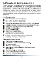
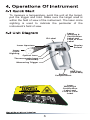
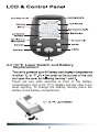
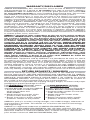
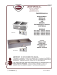
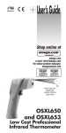
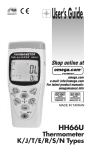
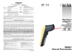
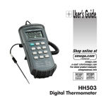
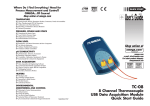
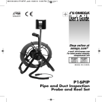
User’s Guide
Shop online at
omega.com
e-mail: [email protected]
For latest product manuals:
omegamanual.info
TM
WITH BUILT-IN
PATENTED
LASER CIRCLE
SIGHTING
OSXL685
and OSXL689
High Performance
Infrared Thermometer
OMEGAnet ® On-Line Service
omega.com
Internet e-mail
[email protected]
Servicing North America:
U.S.A.:
ISO 9001 Certified
Canada:
One Omega Drive, Box 4047
Stamford, CT 06907-0047
Tel: (203) 359-1660
FAX: (203) 359-7700
e-mail: [email protected]
976 Bergar
Laval (Quebec) H7L 5A1, Canada
Tel: (514) 856-6928
FAX: (514) 856-6886
e-mail: [email protected]
For immediate technical or application assistance:
U.S.A. and Sales Service: 1-800-826-6342/1-800-TC-OMEGA®
Canada: Customer Service: 1-800-622-2378/1-800-622-BEST®
Engineering Service: 1-800-872-9436/1-800-USA-WHEN®
Mexico:
En Espa n˜ol: (001) 203-359-7803
FAX: (001) 203-359-7807
e-mail: [email protected]
[email protected]
Servicing Europe:
Czech
Frystatska 184, 733 01 Karviná, Czech Republic
Republic: Tel: +420 (0)59 6311899
FAX: +420 (0)59 6311114
Toll Free: 0800-1-66342
e-mail: [email protected]
Germany Daimlerstrasse 26, D-75392 Deckenpfronn, Germany
Tel:+ 49 (0)7056 9398-0
Austria
FAX: +49 (0)7056 9398-29
Toll Free in Germany: 0800 639 7678
e-mail: [email protected]
United
One Omega Drive, River Bend Technology Centre
Kingdom: Northbank, Irlam, Manchester
ISO 9002
Certified
M44 5BD United Kingdom
Tel: +44 (0)161 777 6611
FAX: +44 (0)161 777 6622
Toll Free in United Kingdom: 0800-488-488
e-mail: [email protected] k
It is the policy of OMEGA Engineering, Inc. to comply with all
worldwide safety and EMC/EMI regulations that apply. OMEGA is
constantly pursuing certification of its products to the European New
Approach Directives. OMEGA will add the CE mark to every
appropriate device upon certification.
The information contained in this document is believed to be
correct, but OMEGA accepts no liability for any errors it contains,
and reserves the right to alter specifications without notice.
WARNING: These products are not designed for use in, and
should not be used for, human applications.
1-3 Warnings and Cautions
2
4
6
6
4-4 Advanced Functions
5.PC Interface (OSXL689)
6.
7.
8.Emissivity Table
6
7
8
11
13
13
14
14
15
temperature, point the unit at the object, pull and hold the
measuring trigger until the temperature is read. Make
sure the target area is larger than the unit’s Field of View.
For large target objects make sure you are within target
distance.
Patented Laser Circle Sighting
30:1 Field of View - OSXL685
50:1 Field of View - OSXL689
Temperature Data Storage
High & Low Audible Alarms
K Type Thermocouple Input - OSXL689
USB PC Interface - OSXL689
1-3 Warnings and Cautions
CAUTION
You may receive harmful laser radiation exposure if you
do not adhere to the warnings listed below:
• Use of controls or adjustments or performance of
procedures other than those specified here may
result in hazardous radiation exposure.
• Do not look at the laser beam coming out of the
lens or view directly with optical instruments - eye
damage can result.
• Use extreme caution when operating the laser
sighting.
• Never point the laser beam at a person.
• Do not attempt to open the thermometer. There are
no user serviceable parts.
• Keep out of the reach of all children.
Refer to the inside back cover for product warning label.
Read the following instruction manual carefully before
attempting to operate the thermometer. Only qualified
personnel should perform repairs which are not covered
in this manual.
OSXL685
OSXL689
-50 to 1000°C (-58 to 1832°F)
From -50 to -20°C (-58 to -4°F)
From -20 to 100°C (-4 to 212°F)
100 to -1000°C (212 to 1832°F)
8 to 14 µm
Adjustable 0.1 to 1.0
30:1
50:1
0 to 50°C, 10 to 90% RH
YES - Laser Circle
Data Storage
Alarms
K Type TC
TC Input Accuracy
USB Port
10 Points
High and Low
–––
-200/1300°C
–––
0.5% Rdg+1°C
–––
YES
3.Specifications con’t.
Laser Sighting
630 to 670 nanometers (red)
Up to 10 ft.
<1mW at 75°F ambient
temperature,
Class II Laser Product
European Classification: Class 2, EN60825-1
FDA Classification:
Complies with 21 CFR Chapter 1,
Subchapter J
Beam Diameter:
5 mm
Beam Divergence:
<2mrad
Laser Configuration:
Dot and Circle
Power Switch:
Slide switch, ON-OFF
Power Indicator:
Laser icon on display
Power:
Supplied by the thermometer
Identification Label:
Located on the right side of the
thermometer
Warning and
Located on the left side of the
Certification Label:
thermometer
Wavelength (Color):
Operating Distance:
Max. Output Optical
Power:
To measure a temperature, point the unit at the target,
pull the trigger and hold. Make sure the target area is
within the field of view of the instrument. The laser circle
sighting is used to indicate the perimeter of the
instrument’s field of view.
ID Label
Laser
Warning &
Certification
Label and
Field of View
Label
Laser Aperture
Display
Screen
Laser
Circle
Sighting
Optical Lens
Thermocouple Input
(OSXL689)
Measuring Trigger
USB Port
(OSXL689)
Battery
Compartment
Laser
Warning &
Certification
Label and
Field of View
Label
6
4-3 °C/°F, Laser Switch and Battery
Replacement
There are two slide switches in front of the battery
compartment. One is for °F/°C display and the other is for
laser sighting. To change the battery, directly place the
battery in the battery compartment.
7
4-4 Advanced Functions
4-4-1 AUTO Mode-Continuous
Operation
From the SCAN mode (Trigger is pulled), you can
lock the trigger electronically and measure
temperature continuously (AUTO mode) by pressing
the LOCK key. The AUTO icon will appear on the
display. Pressing the LOCK key again will disable
the AUTO mode. AUTO icon will disappear from the
display. If the trigger is pulled, the unit stays in the
SCAN mode. If the trigger is released, the unit will go
to HOLD mode and will shut itself off after about 6
seconds.
The following table shows an overall functional flow
chart of the thermometer:
Mode
Press Mode Key
Press Up Key Press Down Key
SCAN
SCAN AUTO
------AUTO
AUTO DATA Record
------DATA DATA RECORD DATA + Memory Location - Memory Location
(Flashing)
(Flashing)
RECORD RECALL (Press M key to record)
DATA DATA RECALL Max Temp + Memory Location - Memory Location
RECALL
Display Data Memory Display Data Memory
Max Temp Max Temp Min Temp + Memory Location - Memory Location
(Flashing)
(Flashing)
Min Temp Min Temp Avg Temp + Memory Location - Memory Location
(Flashing)
(Flashing)
Avg Temp
Avg Temp ∆T
+ Memory Location - Memory Location
(Flashing)
(Flashing)
∆T
∆T TC
+ Memory Location - Memory Location
(Flashing)
(Flashing)
TC
TC Emissivity
+Memory Location –Memory Location
(OSXL689)
(Flashing)
(Flashing)
Emissivity Emissivity High Alarm
+ Emissivity
– Emissivity
HAL
High Alarm Low Alarm + Alarm Set Point – Alarm Set Point
LAL Low Alarm SCAN/HOLD + Alarm Set Point – Alarm Set Point
8
4-4-2 Max, Min, Avg, ∆T Temperature
You can review the Maximum, Minimum, Average,
and differential (Max - Min) temperatures on the
display by pressing the Mode key. If the trigger is
pulled at the same time, the display will show SCAN
icon and all the values are in real time. If the trigger
is released, the display will show the HOLD icon and
all the values are the last readings before the trigger
is released.
4-4-3 Temperature Data Storage
& Recall - DATA Mode
You can store up to 10 temperature data points
(Memory Location 1 thru A). When you are in DATA
RECORD mode, set the memory location using the
Up or Down arrow keys, then press the M key. The
unit will store the temperature data in the current
memory location.
You can review (recall) the stored data by going to
the DATA RECALL mode using the Mode key and
pressing the Up/Down keys. You can then review
memory locations 1 thru A.
NOTE
The unit stores all temperature data, emissivity
value, high and low alarm set points in the
non-volatile memory. Changing the battery will not
affect these values.
9
* In Data Record Mode, pressing the M key will record the
data in the corresponding memory location.
* In Data Recall Mode, you can delete all recorded data by
going to DATA o memory location and pressing the M
key.
* Pulling the Trigger or pressing any of the keys will turn on
LCD backlight.
NOTE
A 6" Surface Probe (Model SPHT-K-6) is included
with Model OSXL689.
10
5. PC Interface (OSXL689)
This infrared thermometer has a USB PC interface. It
comes with a USB cable and CD software. Install the PC
software before connecting the thermometer to the PC
USB port. The minimum PC system requirements are:
• Windows XP
• 64 MB of RAM
• 5 MB of Disk space
After completing the software installation, run the program
and connect the thermometer to the PC using the USB
port. Turn on the thermometer by pulling the trigger. After
a few seconds the PC recognizes the thermometer
connection and a USB icon appears on the thermometer’s
display. The PC now shows the same target temperature
as what is displayed on the thermometer. The
thermometer's trigger is locked by the USB connections so
there is no need to continue pulling the trigger. The
following picture is what you see on the PC.
The target temperature is displayed in either °F or °C.
Then the Date (yy-mm-dd) and Time
(Hour:Minute:Second) are displayed. You can switch
between °F and °C temperature display by clicking on the
unit of measurement (°F or °C).
11
5-1 Recording Temperature Data to a File
Set your recording interval in terms of Hours, Minutes,
Seconds. This is the time interval between every
temperature data point. Than check on Record key. A
selection file text box opens. Enter a text file name, and
click on Save key to start the recording process. Now
temperature data are being saved in the text file at the
specified recording interval. You can determine the
recording process by clicking the Stop key. Now you can
go back and review the data text file.
You can exit the program by clicking the Exit key.
Infrared Thermometer
Target Temperature
125.6
2006-5-02
°C
°F
°F
9:50:26
Hour
Minute
Second
Record Interval
Record
Stop
Exit
12
bring the thermometer closer to the target to ensure
that the target area is larger than the optical field of
view.
OSXL685
64@2000
20@1000
19@500
0.7@20
0.8@40
2.5@80
OSXL689
D:S = 50:1
13
6-2 Emissivity
7. Maintenance
PATENT NOTICE:
U.S. PAT. B1 5,368,392; 5,524,984; 5,727,880; 5,823,678;
5,823,679; 6,123,453; 6,267,500 B1; 6,341,891 B1;
6,377,400 B1; 6,540,398 B2; 6,614,830 B1; 6,633,434 B2;
6,659,639; 6,901,089 B1 / Canada 2,114,806; 2,317,734 /
France 2 756 920; 2 767 921; 2 773 213; 2 773 214 /
Germany G 94 22 197.9; G 94 22 203.7 / Holland
1007752; / U.K. Registered 2,237,493; 2,320,324;
9726133.3 / EPO 0 644,408 B2; EPO 1085 307 A1.
Other U.S. and Foreign Patents Pending.
14
8. Emissivity Table
15
WARRANTY/DISCLAIMER
OMEGA ENGINEERING, INC. warrants this unit to be free of defects in materials
and workmanship for a period of 13 months from date of purchase. OMEGA’s
WARRANTY adds an additional one (1) month grace period to the normal one
(1) year product warranty to cover handling and shipping time. This ensures
that OMEGA’s customers receive maximum coverage on each product.
If the unit malfunctions, it must be returned to the factory for evaluation.
OMEGA’s Customer Service Department will issue an Authorized Return (AR)
number immediately upon phone or written request. Upon examination by
OMEGA, if the unit is found to be defective, it will be repaired or replaced at no
charge. OMEGA’s WARRANTY does not apply to defects resulting from any
action of the purchaser, including but not limited to mishandling, improper
interfacing, operation outside of design limits, improper repair, or unauthorized
modification. This WARRANTY is VOID if the unit shows evidence of having
been tampered with or shows evidence of having been damaged as a result of
excessive corrosion; or current, heat, moisture or vibration; improper specification; misapplication; misuse or other operating conditions outside of OMEGA’s
control. Components in which wear is not warranted, include but are not limite d
to contact points, fuses, and triacs.
OMEGA is pleased to offer suggestions on the use of its various products.
However, OMEGA neither assumes responsibility for any omissions or errors
nor assumes liability for any damages that result from the use of its
products in accordance with information provided by OMEGA, either verbal
or written. OMEGA warrants only that the parts manufactured by the
compamy will be as specified and free of defects. OMEGA MAKES NO
OTHER WARRANTIES OR REPRESENTATIONS OF ANY KIND WHATSOEVER,
EXPRESSED OR IMPLIED, EXCEPT THAT OF TITLE, AND ALL IMPLIED
WARRANTIES INCLUDING ANY WARRANTY OF MERCHANTABILITY AND
FITNESS FOR A PARTICULAR PURPOSE ARE HEREBY DISCLAIMED.
LIMITATION OF LIABILITY: The remedies of purchaser set forth herein are
exclusive, and the total liability of OMEGA with respect to this order,
whether based on contract, warranty, negligence, indemnification, strict
liability or otherwise, shall not exceed the purchase price of the component
upon which liability is based. In no event shall OMEGA be liable for
consequential, incidental or special damages.
CONDITIONS: Equipment sold by OMEGA is not intended to be used, nor shall it
be used: (1) as a “Basic Component” under 10 CFR 21 (NRC), used in or with any
nuclear installation or activity; or (2) in medical applications or used on humans.
Should any Product(s) be used in or with any nuclear installation or activity,
medical application, used on humans, or misused in any way, OMEGA assumes
no responsibility as set forth in our basic WARRANTY / DISCLAIMER language,
and, additionally, purchaser will indemnify OMEGA and hold OMEGA harmless
from any liability or damage whatsoever arising out of the use of the Product(s) in
RETURN REQUESTS / INQUIRIES
Direct all warranty and repair requests/inquiries to the OMEGA Customer
Service Department. BEFORE RETURNING ANY PRODUCT(S) TO OMEGA,
PURCHASER MUST OBTAIN AN AUTHORIZED RETURN (AR) NUMBER FROM
OMEGA’S CUSTOMER SERVICE DEPARTMENT (IN ORDER TO AVOID
PROCESSING DELAYS). The assigned AR number should then be marked on
the outside of the return package and on any correspondence.
The purchaser is responsible for shipping charges, freight, insurance and proper
packaging to prevent breakage in transit.
FOR WARRANTY RETURNS, please
have the following information
available BEFORE contacting OMEGA:
1. Purchase Order number under
which the product was
PURCHASED,
2. Model and serial number of the
product under warranty, and
3. Repair instructions and/or specific
problems relative to the product.
FOR NON-WARRANTY REPAIRS,
consult OMEGA for current repair
charges. Have the following information
available BEFORE contacting OMEGA:
1. Purchase Order number to cover the
COST of the repair,
2. Model and serial number of the
product, and
3. Repair instructions and/or specific
problems relative to the product.
OMEGA’s policy is to make running changes, not model changes, whenever an
improvement is possible. This affords our customers the latest in technology
and engineering.
OMEGA is a registered trademark of OMEGA ENGINEERING, INC.
© Copyright 2006 OMEGA ENGINEERING, INC. All rights reserved. This document may not be copied, photocopied, reproduced, translated, or reduced to any
electronic medium or machine-readable form, in whole or in part, without the
prior written consent of OMEGA ENGINEERING, INC.
Where Do I Find Everything I Need for
Process Measurement and Control?
OMEGA…Of Course!
Shop online at omega.com
TEMPERATURE
䡺
⻬ Thermocouple, RTD & Thermistor Probes,
Connectors, Panels & Assemblies
䡺
⻬ Wire: Thermocouple, RTD & Thermistor
䡺
⻬ Calibrators & Ice Point References
䡺
⻬ Recorders, Controllers & Process Monitors
䡺
⻬ Infrared Pyrometers
PRESSURE, STRAIN AND FORCE
䡺
⻬
䡺
⻬
䡺
⻬
䡺
⻬
Transducers & Strain Gages
Load Cells & Pressure Gages
Displacement Transducers
Instrumentation & Accessories
FLOW/LEVEL
䡺
⻬
䡺
⻬
䡺
⻬
䡺
⻬
Rotameters, Gas Mass Flowmeters & Flow Computers
Air Velocity Indicators
Turbine/Paddlewheel Systems
Totalizers & Batch Controllers
pH/CONDUCTIVITY
䡺
⻬
䡺
⻬
䡺
⻬
䡺
⻬
pH Electrodes, Testers & Accessories
Benchtop/Laboratory Meters
Controllers, Calibrators, Simulators & Pumps
Industrial pH & Conductivity Equipment
DATA ACQUISITION
䡺
⻬
䡺
⻬
䡺
⻬
䡺
⻬
䡺
⻬
Data Acquisition & Engineering Software
Communications-Based Acquisition Systems
Plug-in Cards for Apple, IBM & Compatibles
Datalogging Systems
Recorders, Printers & Plotters
HEATERS
䡺
⻬
䡺
⻬
䡺
⻬
䡺
⻬
䡺
⻬
Heating Cable
Cartridge & Strip Heaters
Immersion & Band Heaters
Flexible Heaters
Laboratory Heaters
ENVIRONMENTAL
MONITORING AND CONTROL
䡺
⻬
䡺
⻬
䡺
⻬
䡺
⻬
䡺
⻬
䡺
⻬
Metering & Control Instrumentation
Refractometers
Pumps & Tubing
Air, Soil & Water Monitors
Industrial Water & Wastewater Treatment
pH, Conductivity & Dissolved Oxygen Instruments
M4296/0606