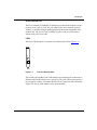
1
Part No. 206379-A
September 1999
4401 Great America Parkway
Santa Clara, CA 95054
Installation and Reference for
the BayStack 21 PCI 10/100
Adapter w/WOL
Copyright © 1999 Nortel Networks.
All rights reserved. September 1999.
The information in this document is subject to change without notice. The statements, configurations, technical data,
and recommendations in this document are believed to be accurate and reliable, but are presented without express or
implied warranty. Users must take full responsibility for their applications of any products specified in this document.
The information in this document is proprietary to Nortel Networks NA Inc.
Trademarks
NORTEL NETWORKS is a trademark of Nortel Networks.
Bay Networks is a registered trademark and BayStack and the Nortel Networks logo are trademarks of Nortel
Networks.
Microsoft, Windows, and Windows NT are registered trademarks of Microsoft Corporation.
All other trademarks and registered trademarks are the property of their respective owners.
USA Requirements Only
Federal Communications Commission (FCC) Compliance Notice: Radio Frequency Notice
This device complies with Part 15 of the FCC Rules. Operation is subject to the following two conditions:
•
•
This device may not cause harmful interference.
This device must accept any interference received, including interference that may cause undesired
operation.
Note: This equipment has been tested and found to comply with the limits for a Class B digital device, pursuant to
Part 15 of the FCC Rules. These limits are designed to provide reasonable protection against harmful interference in a
residential installation. This equipment generates, uses and can radiate radio frequency energy and, if not installed and
used in accordance with the instructions, may cause harmful interference to radio communications. However, there is
no guarantee that interference will not occur in a particular installation. If this equipment does cause harmful
interference to radio or television reception, which can be determined by turning the equipment off and on, the user is
encouraged to try to correct the interference by one or more of the following measures:
•
•
•
•
Reorient or relocate the receiving antenna.
Increase the separation between the equipment and receiver.
Connect the equipment into an outlet on a circuit different from that to which the receiver is connected.
Consult the dealer or an experienced radio/TV technician for help.
EN 55 022 Statement
This is to certify that the Nortel Networks BayStack 21 PCI 10/100 Adapter w/WOL is shielded against the
generation of radio interference in accordance with the application of Council Directive 89/336/EEC, Article 4a.
Conformity is declared by the application of EN 55 022 Class B (CISPR 22).
Warning: This is a Class A product. In a domestic environment, this product may cause radio interference, in which
case, the user may be required to take appropriate measures.
ii
206379-A
EC Declaration of Conformity
This product conforms to the provisions of Council Directive 89/336/EEC and 73/23/EEC. The Declaration of
Conformity is available on the Nortel Networks World Wide Web site at http://libra2.corpwest.baynetworks.com/
cgi-bin/ndCGI.exe/DocView/.
Voluntary Control Council for Interference (VCCI) Statement
Voluntary Control Council for Interference (VCCI) Statement
This is a Class A product based on the standard of the Voluntary Control Council for Interference by Information
Technology Equipment (VCCI). If this equipment is used in a domestic environment, radio disturbance may arise.
When such trouble occurs, the user may be required to take corrective actions.
Canadian Department of Communications Radio Interference
Regulations
This digital apparatus (BayStack 21 PCI 10/100 Adapter w/WOL) do not exceed the Class A limits for radio-noise
emissions from digital apparatus as set out in the Radio Interference Regulations of the Canadian Department of
Communications.
Règlement sur le brouillage radioélectrique du ministère des
Communications
Cet appareil numérique (BayStack 21 PCI 10/100 Adapter w/WOL) respecte les limites de bruits radioélectriques
visant les appareils numériques de classe A prescrites dans le Règlement sur le brouillage radioélectrique du ministère
des Communications du Canada.
206379-A
iii
Electromagnetic Interference (EMI) Statement
Wichtige Sicherheitshinweise
1.
Bitte lesen Sie diese Hinweise sorgfaltig durch.
2.
Heben Sie diese Anleitung fur den spateren Gebrauch auf.
3.
Vor jedem Reinigen ist das Gerat vom Stromnetz zu trennen. Verwenden Sie keine Flussigoder Aerosolreiniger.
Am besten eignet sich ein angefeuchtetes Tuch zur Reinigung.
4.
Um eine Beschadigung des Gerates zu vermeiden sollten Sie nur Zubehorteile verwenden, die vom Hersteller
zugelassen sind.
5.
Das Gerat ist vor Feuchtigkeit zu schutzen.
6.
Bei der Aufstellung des Gerates ist auf sicheren Stand zu achten. Ein Kippen oder Fallen konnte Verletzungen
hervorrufen. Verwenden Sie nur sichere Standorte und beachten Sie die Aufstellhinweise des Herstellers.
7.
Die Beluftungsoffnungen dienen der Luftzirkulation die das Gerat vor Uberhitzung schutzt. Sorgen Sie dafur,
daB diese Offnungen nicht abgedeckt werden.
8.
Beachten Sie beim AnschluB an das Stromnetz die AnschluBwerte.
9.
Die Netzanschlusteckdose muB aus Grunden der elektrischen Sicherheit einen Schutzleiterkontakt haben.
10. Verlegen Sie die NetzanschluBleitung so, daB niemand daruber fallen kann. Es sollte auch nichts auf der Leitung
abgestellt werden.
11. Alle Hinweise und Warnungen, die sich am Geraten befinden sind zu beachten.
12. Wird das Gerat uber einen langeren Zeitraum nicht benutzt, sollten Sie es vom Stromnetztrennen. Somit wird im
Falle einer Uberspannung eine Beschadigung vermieden.
13. Durch die Luftungsoffnungen durfen niemals Gegenstande oder Flussigkeiten in das Gerat gelangen.
Dies konnte einen Brand bzw. elektrischen Schlag auslosen.
14. Offnen sie niemals das Gerat. Das Gerat darf aus Grunden der elektrischen Sicherheit nur von authorisiertem
Servicepersonal geoffnet werden.
iv
206379-A
15. Wenn folgende Situationen auftreten ist das Gerat vom Stromnetz zu trennen und von einer qualifizierten
Servicestelle zu uberprufen:
a. Netzkabel oder Netzstecker sind beschadigt.
b. Flussigkeit ist in das Gerat eingedrungen.
c. Das Gerat war Feuchtigkeit ausgesetzt.
d. Wenn das Gerat nicht der Bedienungsanleitung entsprechend funktioniert oder Sie mit Hilfedieser Anleitung
keine Verbesserung erzielen.
e. Das Gerat ist gefallen und/oder das Gehause ist beschadigt.
f. Wenn das Gerat deutliche Anzeichen eines Defektes aufweist.
16. Bei Reparaturen durfen nur Orginalersatzteile bzw. den Orginalteilen entsprechende Teile verwendet werden.
Der Einsatz von ungeeigneten Ersatzteilen kann eine weitere Beschadigung hervorrufen.
17. Bei Reparaturen durfen nur Orginalersatzteile bzw. den Orginalteilen entsprechende Teile verwendet werden.
Der Einsatz von ungeeigneten Ersatzteilen kann eine weitere Beschadigung hervorrufen.
18. Wenden Sie sich mit allen Fragen die Service und Repartur betreffen an Ihren Servicepartner. Somit stellen Sie
die Betriebssicherheit des Gerates sicher.
19. Zum NetzanschluB dieses Gerates ist eine geprufte Leitung zu verwenden. Fur einen Nennstrom bis 6A und
einem Gerategewicht groBer 3kg ist eine Leitung nicht leichter als H05VV-F, 3G, 0.75mm 2 einzusetzen. Der
arbeitsplatzbezogene Schalldruckpegel nach DIN 45 635 Teil 1000 betragt 70dB(A) oder weniger.
Restricted Rights Legend
Use, duplication, or disclosure by the United States Government is subject to restrictions as set forth in subparagraph
(c)(1)(ii) of the Rights in Technical Data and Computer Software clause at DFARS 252.227-7013.
Notwithstanding any other license agreement that may pertain to, or accompany the delivery of, this computer
software, the rights of the United States Government regarding its use, reproduction, and disclosure are as set forth in
the Commercial Computer Software-Restricted Rights clause at FAR 52.227-19.
Statement of Conditions
In the interest of improving internal design, operational function, and/or reliability, Nortel Networks NA Inc. reserves
the right to make changes to the products described in this document without notice.
Nortel Networks NA Inc. does not assume any liability that may occur due to the use or application of the product(s)
or circuit layout(s) described herein.
Portions of the code in this software product are Copyright © 1988, Regents of the University of California. All rights
reserved. Redistribution and use in source and binary forms of such portions are permitted, provided that the above
copyright notice and this paragraph are duplicated in all such forms and that any documentation, advertising materials,
and other materials related to such distribution and use acknowledge that such portions of the software were developed
by the University of California, Berkeley. The name of the University may not be used to endorse or promote products
derived from such portions of the software without specific prior written permission.
SUCH PORTIONS OF THE SOFTWARE ARE PROVIDED “AS IS” AND WITHOUT ANY EXPRESS OR
IMPLIED WARRANTIES, INCLUDING, WITHOUT LIMITATION, THE IMPLIED WARRANTIES OF
MERCHANTABILITY AND FITNESS FOR A PARTICULAR PURPOSE.
206379-A
v
Nortel Networks NA Inc. Software License Agreement
NOTICE: Please carefully read this license agreement before copying or using the accompanying software or
installing the hardware unit with pre-enabled software (each of which is referred to as “Software” in this Agreement).
BY COPYING OR USING THE SOFTWARE, YOU ACCEPT ALL OF THE TERMS AND CONDITIONS OF
THIS LICENSE AGREEMENT. THE TERMS EXPRESSED IN THIS AGREEMENT ARE THE ONLY TERMS
UNDER WHICH NORTEL NETWORKS WILL PERMIT YOU TO USE THE SOFTWARE. If you do not accept
these terms and conditions, return the product, unused and in the original shipping container, within 30 days of
purchase to obtain a credit for the full purchase price.
1. License Grant. Nortel Networks NA Inc. (“Nortel Networks”) grants the end user of the Software (“Licensee”) a
personal, nonexclusive, nontransferable license: a) to use the Software either on a single computer or, if applicable, on
a single authorized device identified by host ID, for which it was originally acquired; b) to copy the Software solely
for backup purposes in support of authorized use of the Software; and c) to use and copy the associated user manual
solely in support of authorized use of the Software by Licensee. This license applies to the Software only and does not
extend to Nortel Networks Agent software or other Nortel Networks software products. Nortel Networks Agent
software or other Nortel Networks software products are licensed for use under the terms of the applicable Nortel
Networks NA Inc. Software License Agreement that accompanies such software and upon payment by the end user of
the applicable license fees for such software.
2. Restrictions on use; reservation of rights. The Software and user manuals are protected under copyright laws.
Nortel Networks and/or its licensors retain all title and ownership in both the Software and user manuals, including
any revisions made by Nortel Networks or its licensors. The copyright notice must be reproduced and included with
any copy of any portion of the Software or user manuals. Licensee may not modify, translate, decompile, disassemble,
use for any competitive analysis, reverse engineer, distribute, or create derivative works from the Software or user
manuals or any copy, in whole or in part. Except as expressly provided in this Agreement, Licensee may not copy or
transfer the Software or user manuals, in whole or in part. The Software and user manuals embody Nortel Networks’
and its licensors’ confidential and proprietary intellectual property. Licensee shall not sublicense, assign, or otherwise
disclose to any third party the Software, or any information about the operation, design, performance, or
implementation of the Software and user manuals that is confidential to Nortel Networks and its licensors; however,
Licensee may grant permission to its consultants, subcontractors, and agents to use the Software at Licensee’s facility,
provided they have agreed to use the Software only in accordance with the terms of this license.
3. Limited warranty. Nortel Networks warrants each item of Software, as delivered by Nortel Networks and properly
installed and operated on Nortel Networks hardware or other equipment it is originally licensed for, to function
substantially as described in its accompanying user manual during its warranty period, which begins on the date
Software is first shipped to Licensee. If any item of Software fails to so function during its warranty period, as the sole
remedy Nortel Networks will at its discretion provide a suitable fix, patch, or workaround for the problem that may be
included in a future Software release. Nortel Networks further warrants to Licensee that the media on which the
Software is provided will be free from defects in materials and workmanship under normal use for a period of 90 days
from the date Software is first shipped to Licensee. Nortel Networks will replace defective media at no charge if it is
returned to Nortel Networks during the warranty period along with proof of the date of shipment. This warranty does
not apply if the media has been damaged as a result of accident, misuse, or abuse. The Licensee assumes all
responsibility for selection of the Software to achieve Licensee’s intended results and for the installation, use, and
results obtained from the Software. Nortel Networks does not warrant a) that the functions contained in the software
will meet the Licensee’s requirements, b) that the Software will operate in the hardware or software combinations that
the Licensee may select, c) that the operation of the Software will be uninterrupted or error free, or d) that all defects
in the operation of the Software will be corrected. Nortel Networks is not obligated to remedy any Software defect that
cannot be reproduced with the latest Software release. These warranties do not apply to the Software if it has been (i)
altered, except by Nortel Networks or in accordance with its instructions; (ii) used in conjunction with another
vi
206379-A
vendor’s product, resulting in the defect; or (iii) damaged by improper environment, abuse, misuse, accident, or
negligence. THE FOREGOING WARRANTIES AND LIMITATIONS ARE EXCLUSIVE REMEDIES AND ARE
IN LIEU OF ALL OTHER WARRANTIES EXPRESS OR IMPLIED, INCLUDING WITHOUT LIMITATION ANY
WARRANTY OF MERCHANTABILITY OR FITNESS FOR A PARTICULAR PURPOSE. Licensee is responsible
for the security of its own data and information and for maintaining adequate procedures apart from the Software to
reconstruct lost or altered files, data, or programs.
4. Limitation of liability. IN NO EVENT WILL NORTEL NETWORKS OR ITS LICENSORS BE LIABLE FOR
ANY COST OF SUBSTITUTE PROCUREMENT; SPECIAL, INDIRECT, INCIDENTAL, OR CONSEQUENTIAL
DAMAGES; OR ANY DAMAGES RESULTING FROM INACCURATE OR LOST DATA OR LOSS OF USE OR
PROFITS ARISING OUT OF OR IN CONNECTION WITH THE PERFORMANCE OF THE SOFTWARE, EVEN
IF NORTEL NETWORKS HAS BEEN ADVISED OF THE POSSIBILITY OF SUCH DAMAGES. IN NO EVENT
SHALL THE LIABILITY OF NORTEL NETWORKS RELATING TO THE SOFTWARE OR THIS AGREEMENT
EXCEED THE PRICE PAID TO NORTEL NETWORKS FOR THE SOFTWARE LICENSE.
5. Government Licensees. This provision applies to all Software and documentation acquired directly or indirectly by
or on behalf of the United States Government. The Software and documentation are commercial products, licensed on
the open market at market prices, and were developed entirely at private expense and without the use of any U.S.
Government funds. The license to the U.S. Government is granted only with restricted rights, and use, duplication, or
disclosure by the U.S. Government is subject to the restrictions set forth in subparagraph (c)(1) of the Commercial
Computer Software––Restricted Rights clause of FAR 52.227-19 and the limitations set out in this license for civilian
agencies, and subparagraph (c)(1)(ii) of the Rights in Technical Data and Computer Software clause of DFARS
252.227-7013, for agencies of the Department of Defense or their successors, whichever is applicable.
6. Use of Software in the European Community. This provision applies to all Software acquired for use within the
European Community. If Licensee uses the Software within a country in the European Community, the Software
Directive enacted by the Council of European Communities Directive dated 14 May, 1991, will apply to the
examination of the Software to facilitate interoperability. Licensee agrees to notify Nortel Networks of any such
intended examination of the Software and may procure support and assistance from Nortel Networks.
7. Term and termination. This license is effective until terminated; however, all of the restrictions with respect to
Nortel Networks’ copyright in the Software and user manuals will cease being effective at the date of expiration of the
Nortel Networks copyright; those restrictions relating to use and disclosure of Nortel Networks’ confidential
information shall continue in effect. Licensee may terminate this license at any time. The license will automatically
terminate if Licensee fails to comply with any of the terms and conditions of the license. Upon termination for any
reason, Licensee will immediately destroy or return to Nortel Networks the Software, user manuals, and all copies.
Nortel Networks is not liable to Licensee for damages in any form solely by reason of the termination of this license.
8. Export and Re-export. Licensee agrees not to export, directly or indirectly, the Software or related technical data
or information without first obtaining any required export licenses or other governmental approvals. Without limiting
the foregoing, Licensee, on behalf of itself and its subsidiaries and affiliates, agrees that it will not, without first
obtaining all export licenses and approvals required by the U.S. Government: (i) export, re-export, transfer, or divert
any such Software or technical data, or any direct product thereof, to any country to which such exports or re-exports
are restricted or embargoed under United States export control laws and regulations, or to any national or resident of
such restricted or embargoed countries; or (ii) provide the Software or related technical data or information to any
military end user or for any military end use, including the design, development, or production of any chemical,
nuclear, or biological weapons.
206379-A
vii
9. General. If any provision of this Agreement is held to be invalid or unenforceable by a court of competent
jurisdiction, the remainder of the provisions of this Agreement shall remain in full force and effect. This Agreement
will be governed by the laws of the state of California.
Should you have any questions concerning this Agreement, contact Nortel Networks, 4401 Great America Parkway,
P.O. Box 58185, Santa Clara, California 95054-8185.
LICENSEE ACKNOWLEDGES THAT LICENSEE HAS READ THIS AGREEMENT, UNDERSTANDS IT, AND
AGREES TO BE BOUND BY ITS TERMS AND CONDITIONS. LICENSEE FURTHER AGREES THAT THIS
AGREEMENT IS THE ENTIRE AND EXCLUSIVE AGREEMENT BETWEEN NORTEL NETWORKS AND
LICENSEE, WHICH SUPERSEDES ALL PRIOR ORAL AND WRITTEN AGREEMENTS AND
COMMUNICATIONS BETWEEN THE PARTIES PERTAINING TO THE SUBJECT MATTER OF THIS
AGREEMENT. NO DIFFERENT OR ADDITIONAL TERMS WILL BE ENFORCEABLE AGAINST NORTEL
NETWORKS UNLESS NORTEL NETWORKS GIVES ITS EXPRESS WRITTEN CONSENT, INCLUDING AN
EXPRESS WAIVER OF THE TERMS OF THIS AGREEMENT.
viii
206379-A
Contents
Preface
Before You Begin ............................................................................................................xvii
Text Conventions ............................................................................................................xvii
Technical Publications ................................................................................................... xviii
How to Get Help ............................................................................................................ xviii
Chapter 1
Introduction
BayStack 21 PCI Network Interface Card Overview .......................................................1-1
Product Features ............................................................................................................1-2
Product Description ........................................................................................................1-2
BayStack 21 Network Card ......................................................................................1-2
RJ-45 Ethernet Port ...........................................................................................1-2
LEDs ..................................................................................................................1-3
WOL Cable and Connector ................................................................................1-4
System Requirements ..............................................................................................1-5
Operating Environments ..........................................................................................1-5
Cable Requirements ................................................................................................1-6
Fast Ethernet Cables (100 Mb/s) .......................................................................1-6
Ethernet Cables (10 Mb/s) .................................................................................1-6
Chapter 2
Hardware Installation
Package Contents ..........................................................................................................2-1
Installing the BayStack 21 PCI Network Interface Card ..................................................2-2
Connecting the WOL Cable .....................................................................................2-3
206379-A
ix
Chapter 3
Software Installation
Preinstallation .................................................................................................................3-2
Installing the Network Driver in a Windows 95 Environment ..........................................3-2
Configuring the Windows 95 Environment ...............................................................3-6
Configuring the Workstation Identification .........................................................3-6
Configuring the Network Properties ..................................................................3-8
Installing the Network Driver in a Windows 98 Environment ........................................3-12
Configuring the Windows 98 Environment .............................................................3-16
Configuring the Network Properties ................................................................3-16
Installing the Network Driver in a Windows NT Environment .......................................3-18
Configuring the Network Properties .......................................................................3-21
Installing the Network Driver in a Novell NetWare 4.x Environment .............................3-23
Installing the Network Driver in a Novell NetWare Server ......................................3-23
Specifying Driver Parameters ..........................................................................3-24
Installing the Network Card in a Novell NetWare Client .........................................3-25
Chapter 4
Using the WOL Feature
Setting Up the Workstation .............................................................................................4-1
Running the WOL Feature ..............................................................................................4-2
Chapter 5
Troubleshooting
Diagnostic LEDs .............................................................................................................5-1
Hardware Issues .............................................................................................................5-2
Software Issues ..............................................................................................................5-2
Appendix A
Technical Specifications
Product Specifications ................................................................................................... A-1
Software Drivers ............................................................................................................ A-2
x
206379-A
Appendix B
Novell NetWare Reference Information
Novell NetWare Server AUTOEXEC.NCF Files and Parameters .................................. B-1
Sample AUTOEXEC.NCF Files ........................................................................ B-1
Sample AUTOEXEC.NCF File Parameters ....................................................... B-3
Novell NetWare Client Commands and NET.CFG File .................................................. B-5
Client Commands ............................................................................................. B-5
Sample NET.CFG Files ..................................................................................... B-5
Index
206379-A
xi
xii
206379-A
Figures
Figure 1-1.
Link and Activity LEDs .............................................................................1-3
Figure 1-2.
WOL Cable ..............................................................................................1-4
Figure 1-3.
WOL Connector .......................................................................................1-4
Figure 3-1.
New Hardware Found Window—Generic ................................................3-2
Figure 3-2.
New Hardware Found Window—BayStack 21 Network Card ..................3-3
Figure 3-3.
Update Device Driver Wizard Dialog Box—Generic ................................3-3
Figure 3-4.
Update Device Driver Wizard Dialog Box—BayStack 21 Network Card ..3-4
Figure 3-5.
Copying Files Dialog Box .........................................................................3-5
Figure 3-6.
Network Dialog Box—Identification Tab ...................................................3-6
Figure 3-7.
System Settings Change Dialog Box .......................................................3-7
Figure 3-8.
Network Dialog Box—Configuration Tab ..................................................3-8
Figure 3-9.
Select Network Component Type Dialog Box ..........................................3-9
Figure 3-10. Select Network Protocol Dialog Box ........................................................3-9
Figure 3-11. Configuration Tab, BayStack 21 Network Card Selected .......................3-10
Figure 3-12. TCP/IP Properties Dialog Box ...............................................................3-11
Figure 3-13. New Hardware Found Window—Generic ..............................................3-12
Figure 3-14. New Hardware Found Window—BayStack 21 Network Card ................3-13
Figure 3-15. Copying Files Dialog Box .......................................................................3-13
Figure 3-16. Copying Files Dialog Box .......................................................................3-14
Figure 3-17. New Hardware Found Dialog Box ..........................................................3-14
Figure 3-18. System Settings Change Dialog Box .....................................................3-15
Figure 3-19. Network Dialog Box—Configuration Tab ................................................3-16
Figure 3-20. TCP/IP Properties Dialog Box ...............................................................3-17
Figure 3-21. Network Dialog Box—Adapters Tab .......................................................3-18
Figure 3-22. Select Network Adapter Dialog Box .......................................................3-19
Figure 3-23. Select OEM Option Dialog Box ..............................................................3-20
Figure 3-24. Speed/Duplex Mode Dialog Box ............................................................3-20
Figure 3-25. Network Dialog Box—Protocols Tab ......................................................3-21
206379-A
xiii
Figure 3-26. Microsoft TCP/IP Properties Dialog Box ................................................3-22
xiv
Figure 4-1.
Magic Packet Utility Window ....................................................................4-2
Figure 4-2.
Create a List of Hosts on LAN Dialog Box ...............................................4-2
Figure 4-3.
Magic Packet Utility Identification Window ...............................................4-3
Figure 4-4.
NewGroup Window ..................................................................................4-3
Figure 4-5.
Send a Magic Packet to One Host Dialog Box .........................................4-4
206379-A
Tables
Table 1-1.
LED Indications ........................................................................................1-3
Table 1-2.
Supported Operating Systems .................................................................1-5
Table 5-1.
LED Indications ........................................................................................5-1
Table 5-2.
Typical PCI Slot Parameters ....................................................................5-3
Table A-1.
Technical Specifications ......................................................................... A-1
Table A-2.
Available Software Drivers ...................................................................... A-2
Table B-1.
Commands .............................................................................................. B-5
206379-A
xv
xvi
206379-A
Preface
Congratulations on your purchase of a BayStack™ PC network card adapter, the
BayStack 21 PCI 10/100 Adapter w/WOL, which supports workgroups operating
at 10 Mb/s and/or 100 Mb/s transmission speeds. This network card is intended
for use in a desktop workstation. You can use a similar product, the BayStack 22
PC Card Adapter, in a portable (laptop) computer.
Before You Begin
This guide provides information about using the features and capabilities of the
BayStack 21 PCI 10/100 Adapter w/WOL.
This guide is intended for Ethernet local area network (LAN) administrators with
the following background:
•
Working knowledge of PC terminology and operation
•
Working knowledge of 10BASE-T (Ethernet) and 100BASE-TX
(Fast Ethernet) operations
•
Nortel Networks™ network experience
Text Conventions
This guide uses the following text conventions:
bold text
Indicates command names and options and text that
you need to enter.
Example: Enter a:\.
separator ( > )
Shows menu paths.
Example: From the Windows taskbar, choose Start >
Settings > Control Panel.
206379-A
xvii
Installation and Reference for the BayStack 21 PCI 10/100 Adapter w/WOL
Technical Publications
You can print selected technical manuals and release notes free, directly from the
Internet. Go to support.baynetworks.com/library/tpubs/. Find the product for
which you need documentation. Then locate the specific category and model or
version for your hardware or software product. Using Adobe Acrobat Reader, you
can open the manuals and release notes, search for the sections you need, and print
them on most standard printers. You can download Acrobat Reader free from the
Adobe Systems Web site, www.adobe.com.
How to Get Help
If you purchased a service contract for your Nortel Networks product from a
distributor or authorized reseller, contact the technical support staff for that
distributor or reseller for assistance.
If you purchased a Nortel Networks service program, contact one of the following
Nortel Networks Technical Solutions Centers:
xviii
Technical Solutions Center
Telephone Number
Billerica, MA
800-2LANWAN (800-252-6926)
Santa Clara, CA
800-2LANWAN (800-252-6926)
Valbonne, France
33-4-92-96-69-68
Sydney, Australia
61-2-9927-8800
Tokyo, Japan
81-3-5402-7041
206379-A
Chapter 1
Introduction
This chapter provides an overview of the BayStack 21 PCI 10/100 Adapter w/
WOL, including its hardware and software components. The BayStack 21 PCI 10/
100 Adapter w/WOL complements the BayStack 70-Series 10/100 Ethernet
Switches and BayStack 60-Series 10/100 Ethernet Hubs.
Note: BayStack 21 PCI 10/100 Adapter w/WOL is sometimes also referred to
as the BayStack 21 network card in this document.
BayStack 21 PCI 10/100 Adapter w/WOL Overview
You can install the BayStack 21 PCI 10/100 Adapter w/WOL in the workstations,
desktops, or servers of Microsoft® Windows® 95, Windows 98, or Windows NT®
users. The network card provides connectivity to the network using the Wake On
LAN (WOL) feature, an open standard Advanced Configuration Power Interface
(ACPI) function. The standard provides power management support systems
through hardware and operating system integration. The motherboard of the
workstation must have an ACPI architecture to support this feature.
The WOL feature allows you to turn on a remote workstation. When installed in a
workstation that has been turned off, the BayStack 21 network card monitors LAN
traffic for valid wake-up frames. When the network card receives the correctly
addressed wake-up frame, it sends a signal to the motherboard to turn on the
workstation.
206379-A
1-1
Installation and Reference for the BayStack 21 PCI 10/100 Adapter w/WOL
Information Technology (IT) organizations sometimes prefer to perform tasks
such as installing software, running virus scans, and backing up disk drives during
nonbusiness hours to avoid interrupting users during prime usage times.
Although organizations may use remote software installation tools or other
automated software, IT personnel may have to turn on each workstation for the
software to run. This use of IT resources is inefficient and expensive.
The remote wake-up feature gives IT personnel the ability to turn workstations on
remotely. You can use the wake-up capability to turn remote machines on
automatically, thus further decreasing IT personnel tasks. Workstations that have
been turned on can be directed to run virus scans or software upgrades and then to
return to a turned off mode. This combination of remote access and automatic
wake-up feature saves IT personnel time and increases user productivity by
avoiding delays and disruptions during work hours.
Product Features
The BayStack 21 PCI 10/100 Adapter w/WOL provides the following features:
•
Plug-and-play installation for Windows 95 and Windows 98
•
10/100 autonegotiation
•
Wake on LAN (WOL) capability
Product Description
The BayStack 21 PCI 10/100 Adapter w/WOL is a standard-size PC card.
The WOL cable allows you to connect the network card to your workstation and
enable the WOL feature.
BayStack 21 Network Card
The BayStack 21 PCI 10/100 Adapter w/WOL includes the following
components:
1-2
•
RJ-45 port
•
10 megabits per second (Mb/s) and 100 Mb/s Link LEDs
•
Activity LED
•
WOL cable and connector
206379-A
Introduction
RJ-45 Ethernet Port
The RJ-45 10BASE-T/100BASE-TX Ethernet port connects the network card to a
network device, such as a hub. The port adapts to the correct network speed of
10 Mb/s or 100 Mb/s through autonegotiation with the board components of the
network card. The port is wired as an MDI-X port to connect to other devices
without using a crossover cable.
LEDs
The front of the BayStack 21 network card contains three LEDs (Figure 1-1).
LNK
100 10
ACT
9459FA
Figure 1-1.
Link and Activity LEDs
The 10 Mb/s and 100 Mb/s Link LEDs indicate successful network connections to
Ethernet and Fast Ethernet devices, respectively. The Link LEDs remain steady if
the connection is stable. You should check the RJ-45 connection if the LED is not
steady. The Activity LED indicates active network traffic.
206379-A
1-3
Installation and Reference for the BayStack 21 PCI 10/100 Adapter w/WOL
Table 1-1 describes the Link and Activity LED indications.
Table 1-1.
LED Indications
Label
Color
Activity
Description
10 LNK
Green
On
A 10 Mb/s connection has been established.
Off
Power is not supplied to the network card, or a 10 Mb/s
connection is not established.
On
A 100 Mb/s connection has been established.
Off
Power is not supplied to the network card, or a 100 Mb/s
connection is not established.
On
Heavy network traffic is passing through the port.
Blinking
Intermittent or light network traffic is passing through the port.
The rate of blinking is proportional to the amount of network
traffic.
100 LNK
ACT
Green
Green
WOL Cable and Connector
The WOL cable (Figure 1-2) is an interconnect cable with standard 3-pin
connectors on each end.
9461FA
Figure 1-2.
WOL Cable
The WOL cable includes the following three wires:
1-4
•
A network card auxiliary power supply line, which maintains constant
low-level power to the motherboard
•
A card wake-up signal line, which turns on the workstation remotely
•
A ground line, which provides electrical grounding
206379-A
Introduction
One end of the cable connects to the motherboard of your workstation. The other
end attaches to the WOL connector (Figure 1-3) on the board of the BayStack 21
network card.
WOL connector
9460EA
Figure 1-3.
WOL Connector
System Requirements
Workstations using the BayStack 21 PCI 10/100 Adapter w/WOL must meet the
following requirements:
206379-A
•
Microsoft Windows 95, Windows 98, or Windows NT
•
PCI expansion slot with bus mastering capability
1-5
Installation and Reference for the BayStack 21 PCI 10/100 Adapter w/WOL
Operating Environments
The BayStack 21 network card supports the operating systems and associated
drivers listed in Table 1-2.
Table 1-2.
1-6
Supported Operating Systems
Driver
Operating Systems
ODI Drivers
•
•
Novell NetWare 3.12, 4.1, 4.11
Novell LAN Analyzer
NDIS 2.0 Drivers
•
•
•
•
Microsoft LAN Manager
IBM LAN Server
IBM LAN Support
DEC PATHWORKS
NDIS 3.0 Drivers
•
•
•
Windows for Workgroups 3.11
Windows 95
Windows NT 3.51
NDIS 4.0 Drivers
•
Windows 95 OSR2, 98, NT 4.0
NDIS 5.0 Drivers
•
Windows 98
Packet Drivers
•
•
FTP PC/TCP
NCSA TCP/IP
UNIX Drivers
•
•
SCO UNIX
Linux
206379-A
Introduction
Cable Requirements
You can use Category 5 (Cat 5) Ethernet cables for 10 Mb/s and 100 Mb/s
network connections to the BayStack 21 network card.
Use the following guidelines when using Cat 5 cables:
•
Maximum length between a workstation and a hub is 100 meters (m).
•
Maximum length between two hubs is 10 m.
•
Maximum length between two hubs which are functioning as Ethernet Class 2
Repeaters is 100 m.
•
Maximum total length between two workstations is 205 m.
Fast Ethernet Cables (100 Mb/s)
You must use a Cat 5 straight-through cable with one RJ-45 connector on each end
for 100 Mb/s Ethernet connections. Do not use a crossover cable.
Ethernet Cables (10 Mb/s)
You can use Cat 3, Cat 4, or Cat 5 unshielded twisted pair (UTP) cable or an
EIA/TIA-568 100 ohm shielded twisted pair (STP) cable for 10 Mb/s Ethernet
connections. You must use a straight through cable with one RJ-45 connector on
each end. Do not use a crossover cable.
206379-A
1-7
Chapter 2
Hardware Installation
This chapter describes how to install the BayStack 21 PCI 10/100 Adapter w/
WOL in an end-user workstation such as a desktop computer or server.
Package Contents
The BayStack 21 network card package contains the following:
•
BayStack 21 PCI 10/100 Adapter w/WOL with one RJ-45 port
•
WOL cable
•
BayStack 21 PCI 10/100 Adapter w/WOL Software & Documentation CD,
including technical documentation in PDF format
•
Safety card
•
Warranty/Registration card
Caution: Touch a grounded metal object to free yourself of static electricity
prior to handling the network card.
206379-A
2-1
Installation and Reference for the BayStack 21 PCI 10/100 Adapter w/WOL
Installing the BayStack 21 PCI 10/100 Adapter w/WOL
To install the BayStack 21 network card in a workstation:
1.
Shut down the workstation.
2.
Unplug the workstation power cord from the power source.
3.
Remove the chassis cover of the workstation.
4.
Locate an available PCI bus master expansion slot in the workstation.
5.
Remove the protective bracket from the slot.
6.
Insert the contact edge of the BayStack 21 network card into the slot.
7.
Make sure all edge connectors of the network card are firmly seated in
the slot.
8.
Install and secure the bracket screw to secure the network card to the
chassis.
9.
If you plan to install the WOL cable, proceed to “Connecting the WOL
Cable” on page 2-3. Otherwise, continue with steps 10 through 12.
10. Replace the chassis.
11. Install a standard Ethernet cable to the BayStack 21 network card.
a.
Plug one end of the network cable into the RJ-45 connector of the
network card.
b.
Plug the other end of the network cable into an RJ-45 port on the
network device.
12. Reconnect the power cord and turn the workstation on.
Note: If the Basic Input/Output System (BIOS) section of your workstation
boot program is “Plug and Play” compliant, the BIOS will automatically
configure a newly installed network card.
If the BIOS program has assigned your network card an interrupt number that
is already assigned to another device, both devices will fault. If you detect this
problem, you must run the CMOS Setup Utility to manually assign a
nonconflicting interrupt number.
2-2
206379-A
Hardware Installation
Connecting the WOL Cable
To install the WOL cable between the BayStack 21 network card and the chassis:
1.
Make sure that the workstation is disconnected from the power source
and the chassis cover has been removed.
2.
Connect one end of the WOL cable to the network card WOL connector.
You can use either connector on the WOL cable; they are identical. Refer to
Figure 1-3 on page 1-5 for the location of the WOL connector on the network
card.
3.
Identify the WOL connector location on the workstation motherboard.
The location of the connector is system dependent. You may see “WOL”
written on the motherboard.
4.
Connect the other end of the WOL cable to the motherboard.
Caution: If the WOL connector on the motherboard does not fit the connector
on the WOL cable, or if the WOL connector does not have three pins, do not
force the connection or alter the components. Using an incorrect connector can
damage the workstation.
5.
Replace the chassis.
6.
Install a standard Ethernet cable to the BayStack 21 network card.
a.
Plug one end of the network cable into the RJ-45 connector of the
network card.
b.
Plug the other end of the network cable into a port on the network
hub.
7.
Reconnect the power cord and turn the workstation on.
8.
Press the Delete key to enter the BIOS CMOS Setup.
9.
Enable the WOL function or the power-on function of the workstation.
The name of this function is architecture dependent. The function may be
located in a category heading such as “Power Management.”
10. Test the WOL function from the workstation you just connected or from
another remote workstation that has a network card installed.
206379-A
2-3
Chapter 3
Software Installation
This chapter provides instructions for installing the Windows- and Novell
NetWare-based BayStack 21 network driver software and configuring the
BayStack 21 PCI 10/100 Adapter w/WOL on your network. This chapter
describes procedures for Windows 95, Windows 98, Windows NT, and Novell
NetWare 4.x. Drivers for other operating systems are available but not discussed in
this guide. You can access information for installing other drivers from the
BayStack 21 PCI 10/100 Adapter w/WOL Software & Documentation CD.
Different versions of Windows may have different installation screens than those
shown in these instructions. Your installation screens may appear in a different
order than the screens in this chapter, or you may encounter more or fewer
screens. You will be prompted for the same information, regardless of the
Windows version.
The driver starts automatically for Windows 95 and Windows 98. Nortel Networks
recommends using the automatic process to take advantage of this
“plug-and-play” capability. The driver must be manually configured for
Windows NT.
206379-A
3-1
Installation and Reference for the BayStack 21 PCI 10/100 Adapter w/WOL
Preinstallation
Perform the following tasks prior to installing the BayStack 21 network driver:
•
You must install the BayStack 21 network card before installing the BayStack
21 network driver.
•
You must have the Windows 95 or Windows 98 CD and the BayStack 21
network driver CD ready to use during the installation. You may be prompted
to install either CD. You may receive the “Insert Disk” and the “Please insert
the disk labeled Windows...” messages. If you get these messages, insert the
appropriate CD, enter the appropriate drive letter and CD name, and click OK
to continue the installation. For example, if drive D is your CD drive and you
insert the Windows 95 CD, enter d:\win95 when prompted.
Installing the Network Driver in a Windows 95 Environment
This section describes the steps required to install the BayStack 21 network driver
in a Windows 95 workstation. Be sure you have performed the tasks in
“Preinstallation” on page 3-2 before continuing.
To install the network driver:
1.
Turn on the power to the workstation, and start Windows 95.
The New Hardware Found window opens, identifying a generic network card.
For instance, the window may list “PCI Ethernet Controller” (Figure 3-1).
New Hardware Found
PCI Ethernet Controller
Select which driver you want to install for your new hardware:
Figure 3-1.
3-2
9562DA
New Hardware Found Window—Generic
206379-A
Software Installation
A second New Hardware Found window opens, identifying your BayStack 21
PCI 10/100 Adapter w/WOL (Figure 3-2).
New Hardware Found
BayStack 21 10/100 PCI Ethernet PCI Adapter
Select which driver you want to install for your new hardware:
Figure 3-2.
9563DA
New Hardware Found Window—BayStack 21
Network Card
The Building Driver Information Database window opens. You do not have to
perform any tasks.
A generic Update Device Driver Wizard dialog box opens (Figure 3-3).
Figure 3-3.
206379-A
Update Device Driver Wizard Dialog Box—Generic
3-3
Installation and Reference for the BayStack 21 PCI 10/100 Adapter w/WOL
2.
Insert the BayStack 21 PCI 10/100 Adapter w/WOL Software &
Documentation CD into the CD drive.
3.
Click Next.
The next Update Device Driver Wizard dialog box (Figure 3-4) indicates
that the new BayStack 21 network card has been found and the driver is
automatically loaded.
Update Device Driver Wizard
Windows found the following updated driver for this
device:
BayStack 21 10/100 PCI Ethernet PCI Adapter
If you want to use this driver, click Finish. If this is not the
correct driver and you want to search for a different driver
manually, click Other Locations.
Location of Driver
Other Locations...
< Back
Finish
Cancel
8527DB
Figure 3-4.
3-4
Update Device Driver Wizard Dialog Box—BayStack 21
Network Card
206379-A
Software Installation
4.
Click Finish.
The Copying Files dialog box opens (Figure 3-5).
Copying Files...
The file NETB21ND.inf on Windows 95 CD-ROM
could not be found.
Insert Windows 95 CD-ROM into the drive
selected below, and click OK.
OK
Cancel
Skip File
Details...
Copy files from:
D:\
8528DB
Figure 3-5.
Copying Files Dialog Box
5.
Insert the BayStack 21 PCI 10/100 Adapter w/WOL Software &
Documentation CD as indicated.
6.
Enter the drive letter of the CD drive into the “Copy files from:” field.
For example, if the CD drive in your workstation is drive D, enter D:\.
7.
Click OK.
The Copying Files dialog box opens again.
8.
Insert the Windows 95 CD as indicated.
9.
Enter D:\WIN95 into the “Copy files from” field.
10. Click OK.
The System Settings Change dialog box opens.
11. Remove any CDs from your CD drive.
12. Click Yes.
Restarting your system is necessary to enable your PC to finish setting up
your new hardware.
206379-A
3-5
Installation and Reference for the BayStack 21 PCI 10/100 Adapter w/WOL
Configuring the Windows 95 Environment
You must configure the Windows 95 environment on your workstation after you
install the BayStack 21 network driver. Configure your workstation identification
first, and then configure TCP/IP properties.
Configuring the Workstation Identification
To configure the workstation identification:
1.
From the Windows taskbar, choose Start > Settings > Control Panel.
2.
Double-click Network.
The Network dialog box opens.The configuration tab is displayed by default.
3.
Select the Identification tab (Figure 3-6).
Figure 3-6.
3-6
Network Dialog Box—Identification Tab
206379-A
Software Installation
4.
5.
Enter the following information for your workstation:
•
Computer Name—The name assigned to your workstation by your
system administrator
•
Workgroup—Typically, the location or group name assigned by your
system administrator
•
Computer Description—The manufacturing description; usually appears
by default
Click OK.
Files automatically copy. The Copying Files dialog box opens.
6.
Enter the location of the requested files or CD in the “Copy files from:”
field.
7.
Click OK.
The System Settings Change dialog box opens (Figure 3-7).
Figure 3-7.
System Settings Change Dialog Box
Restarting your system is necessary to enable your PC to finish setting up
your new hardware.
8.
Remove any CDs from your CD drive.
9.
Click Yes.
Your system will restart.
206379-A
3-7
Installation and Reference for the BayStack 21 PCI 10/100 Adapter w/WOL
Configuring the Network Properties
To configure the network properties of your workstation, such as TCP/IP
protocols:
1.
From the Windows taskbar, choose Start > Settings > Control Panel.
2.
Click Network.
The Network dialog box opens. The configuration tab (Figure 3-8) is
displayed by default.
Figure 3-8.
3-8
Network Dialog Box—Configuration Tab
206379-A
Software Installation
3.
Click Add.
The Select Network Component Type dialog box opens (Figure 3-9).
Figure 3-9.
Select Network Component Type Dialog Box
4.
Select Protocol.
5.
Click Add.
The Select Network Protocol dialog box opens (Figure 3-10).
Figure 3-10.
206379-A
Select Network Protocol Dialog Box
3-9
Installation and Reference for the BayStack 21 PCI 10/100 Adapter w/WOL
6.
In the Manufacturers list, select Microsoft.
7.
In the Network Protocols list, select TCP/IP.
8.
Click OK.
9.
Return to the Configuration tab.
10. Select Nortel BayStack 21 10/100 PCI Ethernet Adapter (Figure 3-11).
Figure 3-11.
3-10
Configuration Tab, BayStack 21 Network Card Selected
206379-A
Software Installation
11. Click Properties.
The TCP/IP Properties dialog box opens (Figure 3-12).
Figure 3-12.
TCP/IP Properties Dialog Box
12. Select the IP Address tab.
13. If the workstation has a static IP address, specify the IP address, subnet
mask, and default gateway of your workstation.
You can also choose the “Obtain an IP address automatically” option if the
workstation does not have a static IP address. If you choose this option, your
IP address will be supplied by a DHCP server.
206379-A
3-11
Installation and Reference for the BayStack 21 PCI 10/100 Adapter w/WOL
14. Use the Gateway or DNS Configuration tabs to configure other
parameters, as needed.
15. Click OK.
The Copying Files dialog box opens.
16. In the “Copy files from:” field, enter the location of the requested files or
CD.
17. Click OK.
The system restart dialog box opens. Restarting your system is necessary to
enable your PC to finish setting up your new hardware.
18. Remove all CDs from the CD drive.
19. Click Yes.
Your system restarts.
Installing the Network Driver in a Windows 98 Environment
This section describes the steps required to install the BayStack 21 network driver
in a Windows 98 workstation.
To install the network driver:
1.
Turn on the power to the workstation, and start Windows 98.
The New Hardware Found window opens, identifying a generic network card.
For instance, the window may list “PCI Ethernet Controller” (Figure 3-13).
New Hardware Found
PCI Ethernet Controller
Select which driver you want to install for your new hardware:
Figure 3-13.
3-12
9562DA
New Hardware Found Window—Generic
206379-A
Software Installation
A second New Hardware Found window opens, identifying your BayStack 21
PCI 10/100 Adapter w/WOL (Figure 3-14).
New Hardware Found
BayStack 21 10/100 PCI Ethernet PCI Adapter
9563DA
Select which driver you want to install for your new hardware:
Figure 3-14.
New Hardware Found Window
The Copying Files dialog box opens (Figure 3-15).
Copying Files...
The file NETB21ND.cat on Windows 98 CD-ROM
could not be found.
Insert Windows 98 CD-ROM into the drive
selected below, and click OK.
OK
Cancel
Skip File
Details...
Copy files from:
D:\
8528DC
Figure 3-15.
Copying Files Dialog Box
2.
Insert the required CD into the CD drive of your workstation.
3.
Enter the location and file name of the CD in the “Copy files from:” field.
For instance, enter D:\nt_9x if you inserted the Windows 98 CD into drive D.
206379-A
3-13
Installation and Reference for the BayStack 21 PCI 10/100 Adapter w/WOL
4.
Click OK.
The Copying Files dialog box opens (Figure 3-16).
Figure 3-16.
Copying Files Dialog Box
5.
Insert the required CD into the CD drive of your workstation.
6.
Enter the location and file name of the CD in the “Copy files from:” field.
7.
Click OK.
The install program searches the CD. The New Hardware Found dialog box
opens (Figure 3-17).
Figure 3-17.
3-14
New Hardware Found Dialog Box
206379-A
Software Installation
8.
9.
Select one of the following options:
•
Driver from disk provided by hardware manufacturer (recommended by
Nortel Networks)
•
Do not install a driver (Windows will not prompt you again)
•
Select from a list of alternate drivers
Click OK.
The System Settings Change dialog box opens (Figure 3-18).
Figure 3-18.
System Settings Change Dialog Box
Restarting your system is necessary to enable your PC to finish setting up
your new hardware.
10. Remove all CDs from the CD drive.
11. Click Yes.
Your system restarts.
206379-A
3-15
Installation and Reference for the BayStack 21 PCI 10/100 Adapter w/WOL
Configuring the Windows 98 Environment
You must configure the Windows 98 environment on your workstation after you
install the BayStack 21 network driver.
Configuring the Network Properties
To configure the network properties for your workstation:
1.
From the Windows taskbar, choose Start > Settings > Control Panel.
2.
Double-click Network.
The Network dialog box opens. The TCP/IP network protocol for the
BayStack 21 network driver is already installed.
The configuration tab (Figure 3-19) is displayed by default.
Figure 3-19.
3.
3-16
Network Dialog Box—Configuration Tab
Select Nortel BayStack 21 10/100 PCI Ethernet Adapter.
206379-A
Software Installation
4.
Click Properties.
The TCP/IP Properties dialog box opens (Figure 3-20).
Figure 3-20.
TCP/IP Properties Dialog Box
5.
Select the IP Address tab.
6.
If the workstation has a static IP address, specify the IP address, subnet
mask, and default gateway of your workstation.
You can also choose the “Obtain an IP address automatically” option if the
workstation does not have a static IP address. If you choose this option, your
IP address will be supplied by a DHCP server.
7.
Use the Gateway or DNS Configuration tabs to configure other
parameters, as needed.
8.
Click OK.
The System Settings Change dialog box opens.
206379-A
3-17
Installation and Reference for the BayStack 21 PCI 10/100 Adapter w/WOL
9.
Click Yes.
Your system restarts.
Installing the Network Driver in a Windows NT Environment
The Windows NT installation of the BayStack 21 network driver is not automatic.
You must install the driver manually.
To install the network driver:
1.
From the Windows taskbar, choose Start > Settings > Control Panel.
2.
Double-click Network.
The Network dialog box opens. The Identification tab is displayed by default.
3.
Select the Adapters tab (Figure 3-21).
Figure 3-21.
3-18
Network Dialog Box—Adapters Tab
206379-A
Software Installation
4.
Select Add.
The Select Network Adapter dialog box opens (Figure 3-22).
Figure 3-22.
Select Network Adapter Dialog Box
5.
Click Have Disk.
6.
Insert the BayStack 21 PCI 10/100 Adapter w/WOL Software &
Documentation CD into the CD drive.
7.
Specify the letter of the drive into which you installed the CD.
Typically the CD drive is letter D.
206379-A
3-19
Installation and Reference for the BayStack 21 PCI 10/100 Adapter w/WOL
8.
Click OK.
The Select OEM Option dialog box opens (Figure 3-23).
Figure 3-23.
9.
Select OEM Option Dialog Box
Select Nortel BayStack 21 10/100 PCI Ethernet Adapter.
10. Click OK.
The Speed/Duplex Mode dialog box (Figure 3-24) opens. The default mode is
Auto.
Figure 3-24.
Speed/Duplex Mode Dialog Box
11. Select Auto.
12. Click OK.
3-20
206379-A
Software Installation
Configuring the Network Properties
To configure the network properties for your workstation:
1.
From the Windows taskbar, choose Start > Settings > Control Panel.
2.
Double-click Network.
The Network dialog box opens. The Identification tab is displayed by default.
3.
Click the Protocols tab.
The Protocols tab (Figure 3-25) is displayed.
Figure 3-25.
206379-A
Network Dialog Box—Protocols Tab
3-21
Installation and Reference for the BayStack 21 PCI 10/100 Adapter w/WOL
4.
Click Properties.
The Microsoft TCP/IP Properties dialog box opens (Figure 3-26).
Figure 3-26.
5.
Microsoft TCP/IP Properties Dialog Box
If the workstation has a static IP address, specify the IP address, subnet
mask, and default gateway of your workstation.
You can also choose the “Obtain an IP address from a DHCP server” option if
the workstation does not have a static IP address.
3-22
6.
Use the DNS tab to add additional network parameters, if needed.
7.
Click OK.
206379-A
Software Installation
8.
Click Close.
The System Settings Change dialog box opens. Restarting your system is
necessary to enable your PC to finish setting up your new hardware.
9.
Click Yes.
Your system restarts.
Installing the Network Driver in a Novell NetWare 4.x
Environment
This section describes the steps required to install the BayStack 21 network driver
software in a Novell NetWare version 4.x environment. You must install and
configure the software on your Novell server and client.
If you are installing the BayStack 21 network driver software in a Novell NetWare
version 3.12 environment, refer to the Readme.txt file on the BayStack 21 PCI 10/
100 Adapter w/WOL Software & Documentation CD.
Installing the Network Driver in a Novell NetWare Server
To install the BayStack 21 network driver in a Novell NetWare server:
1.
2.
Verify that your Novell NetWare server includes the following files:
•
\NETWARE\SERVER\4.X\MSM.NLM (Media Support Module)
•
\NETWARE\SERVER\ETHERTSM.NLM (Topology Specific Module for
Ethernet)
Change to the Novell NetWare server directory.
For instance, type the command:
CD\NWSERVER
3.
Type:
SERVER
4.
Press Enter.
5.
At the server prompt, enter:
LOAD INSTALL
6.
206379-A
From the Installation Options menu, select Driver options.
3-23
Installation and Reference for the BayStack 21 PCI 10/100 Adapter w/WOL
7.
Press Enter.
8.
From the Driver Options menu, select Configure network drivers.
9.
Press Enter.
10. From the Additional Driver Actions menu, select Select a driver.
11. Press Enter.
12. Press Insert to install an unlisted driver.
By default, your a: drive is scanned.
13. Press <F3> to specify another path or drive.
14. Insert the BayStack 21 PCI 10/100 Adapter w/WOL Software &
Documentation CD into the CD drive of your server.
15. Press Enter.
The following file automatically copies from the BayStack 21 PCI 10/100
Adapter w/WOL Software & Documentation CD to your Novell NetWare
server:
•
\NETWARE\SERVER\B21LAN10.LAN
16. From the Select a driver to install: menu, select Nortel 21 10/100 PCI
Ethernet Driver.
17. Press Enter.
The “Do you want to copy driver B21LAN10.LAN (Y)(N)” message is
displayed.
18. Select Yes.
19. Proceed to the next section if you want to specify driver parameters.
Specifying Driver Parameters
The BayStack 21 network driver installs with default parameters. You can set
specific driver parameters for the server.
3-24
206379-A
Software Installation
To set specific driver parameters:
1.
From the Board B21LAN10_ 1 (Driver B21LAN10) Actions menu, select
“Select/Modify driver parameters and protocols.”
2.
Press Enter.
The default protocol is IPX. You can also select TCP/IP or AppleTalk.
3.
Select a protocol from the available options.
4.
Specify the slot number (slot #).
5.
Select “Save parameter and load select driver.”
If you select the IPX protocol, the network number (network #) is randomly
generated.
6.
206379-A
Press Enter at each of the following four prompts:
•
802.3
•
802.2
•
SNAP
•
Ethernet II
3-25
Installation and Reference for the BayStack 21 PCI 10/100 Adapter w/WOL
Installing the Network Card in a Novell NetWare Client
To install the BayStack 21 network driver in your Novell NetWare client:
1.
Verify that your BayStack 21 network card is properly installed in your
Novell NetWare workstation.
2.
Insert the BayStack 21 Network Driver CD into the CD drive in your
workstation.
3.
Access the Novell NetWare client directory.
4.
Copy the following command to the client directory:
\NETWARE\DOSODI\B21ODI10.COM
5.
Enter the following commands, in order:
lsl
b21odi10
ipxodi
netx (or vlm)
6.
Press Enter.
You can now log in to your network.
7.
Edit the NET.CFG file to change driver parameters.
8.
Verify that there is a protocol binding for Ethernet 802.3 in the NET.CFG
file.
Refer toAppendix B, “Novell NetWare Reference Information” for sample
NET.CFG files.
3-26
206379-A
Chapter 4
Using the WOL Feature
You can use the Wake On LAN (WOL) feature to start up remote workstations
without end-user intervention. A BayStack 21 PCI 10/100 Adapter w/WOL must
be installed on each workstation that you want to start remotely. You must set up
each workstation prior to using the WOL feature.
Setting Up the Workstation
Perform the following tasks prior to using the WOL feature on a remote
workstation:
•
Make sure the WOL connector is attached to the BayStack 21 network card
and to the motherboard of the workstation.
Refer to “Connecting the WOL Cable” on page 2-3 for instructions.
•
206379-A
Place the workstation in sleep (or standby) mode, or turn the workstation off
completely.
4-1
Installation and Reference for the BayStack 21 PCI 10/100 Adapter w/WOL
Running the WOL Feature
You must have a WOL-capable utility on the workstation from which you are
using the WOL feature to turn on remote workstations. There are several
commercially available utilities. As an example, instructions for using the AMD
Magic Packet Utility are provided in this section. You can obtain this utility from
www.amd.com. Procedures for utilities from other companies vary.
To use the WOL feature:
1.
Figure 4-1.
Open a WOL utility, such as the Magic Packet Utility (Figure 4-1).
Magic Packet Utility Window
2.
From the Magic Packet Utility menu, select Magic Packets > Create a
List of Hosts.
The Create a List of Hosts on LAN dialog box opens (Figure 4-2).
Figure 4-2.
4-2
Create a List of Hosts on LAN Dialog Box
206379-A
Using the WOL Feature
3.
Enter the subnet mask of the remote workstation you want to turn on.
The utility maps, or locates, BayStack 21 network cards in the subnet you
specified. Make sure the remote workstation is still turned on. It should not be
in standby or shutdown mode.
4.
Click OK.
The Magic Packet Utility identification window opens (Figure 4-3).
Figure 4-3.
5.
Magic Packet Utility Identification Window
Click OK.
The NewGroup window opens (Figure 4-4), displaying information about the
remote workstation you want to turn on.
Figure 4-4.
NewGroup Window
You can now turn on the remote workstation. Continue with these instructions
when the workstation is in standby or shutdown mode.
206379-A
4-3
Installation and Reference for the BayStack 21 PCI 10/100 Adapter w/WOL
6.
Return to the Magic Packet Utility menu.
7.
Select Magic Packet > Power on One Host.
The Send a Magic Packet to One Host dialog box opens (Figure 4-5).
Figure 4-5.
Send a Magic Packet to One Host Dialog Box
8.
Enter the physical address of the remote workstation you want to turn on.
Do not enter the IP address.
9.
Click Send.
The utility sends a packet to the BayStack 21 network card on the remote
workstation to turn on the workstation.
10. Click Close.
4-4
206379-A
Chapter 5
Troubleshooting
This chapter provides several methods for troubleshooting problems related to the
BayStack 21 PCI 10/100 Adapter w/WOL.
Diagnostic LEDs
Three LEDs on the front of the BayStack 21 network card provide diagnostic
information. The 10 Mb/s and 100 Mb/s Link LEDs indicate successful network
connections to Ethernet and Fast Ethernet devices, respectively. The Link LEDs
remain steady if the connection is stable. You should check the RJ-45 connection
if the LED is not steady. The Activity LED indicates active network traffic.
Table 5-1 describes the Link and Activity LED indications.
Table 5-1.
LED Indications
Label
Color
Activity
Description
10 LNK
Green
On
A 10 Mb/s connection has been established.
Off
Power is not supplied to the network card, or a 10 Mb/s
connection is not established.
On
A 100 Mb/s connection has been established.
Off
Power is not supplied to the network card, or a 100 Mb/s
connection is not established.
On
Heavy network traffic is passing through the port.
Blinking
Intermittent or light network traffic is passing through the port.
The rate of blinking is proportional to the amount of network
traffic.
100 LNK
ACT
206379-A
Green
Green
5-1
Installation and Reference for the BayStack 21 PCI 10/100 Adapter w/WOL
Hardware Issues
Perform the following tasks to check for hardware problems:
•
Verify that you are using the correct cables and the correct cable lengths, as
described in “Cable Requirements” on page 1-7.
•
Make sure the network cable is firmly connected to the network card and to a
network device.
•
Connect the Ethernet cable to a different port on the network device.
•
Verify that the BayStack 21 network card is fully and firmly seated in the slot
connector in the workstation chassis. Check the connector edges of the card
for damage.
•
Replace the network card in question with a network card that you are sure
functions properly. Run generic network interface card diagnostic tests.
•
Install the network card in question into another workstation and run the tests
again.
•
Remove all other network cards from the workstation and run the tests again.
If the verification/diagnostic run is not normal, there is probably an interrupt
number conflict. You must manually resolve the conflict by running a CMOS
Setup utility after you have reinstalled the expansion cards.
Software Issues
Perform the following tasks to check for software problems:
5-2
•
Verify that the proper driver is loaded, as explained in Chapter 3, “Software
Installation.” Be sure you followed the directions for the operating system you
are running on the workstation.
•
Check that the new configurations match the configurations of the network
device if you have manually configured the speed or mode of the network
card. Nortel Networks recommends setting the network card to
autonegotiation when installing the network driver.
206379-A
Troubleshooting
•
Verify that the PCI slot in the workstation is an enabled bus-master slot.
Do not use a slave PCI slot for the BayStack 21 network card. Some
computers may require that you configure the PCI slot to enable bus
mastering. Refer to your computer manual for information about the PCI
BIOS setup program.
Be sure that the slot is configured for level-triggered interrupts. It should not
be configured for edge-triggered interrupts. Table 5-2 describes typical PCI
parameter configurations. Parameters may vary in different systems.
Table 5-2. Typical PCI Slot Parameters
Parameter
Configuration
PCI Slot #
Slot number where the network card is installed
Master
Enabled
Slave
Enabled
Latency Timer
40 (range: 20 to 255)
Interrupt Type
Level-triggered
Interrupt Number
Choice of any number that the BIOS setup program
supplies. (The interrupt number should not conflict
with other installed cards.)
•
Verify that your BIOS software correctly supports the PCI Local Bus
Specification, version 2.0 or later. Upgrade your BIOS software if needed.
•
Determine whether or not the network card slot is deactivated at the BIOS
level. Use the CMOS Setup utility in your workstation to provide the option to
activate or deactivate slots.
•
Disable the Plug and Play option (PnP) in the BIOS setup program, if your
computer does not require this option. Incorrectly assigned resources between
network cards may cause a problem.
Note: Always consult your computer manual for information about changing
motherboard jumper and BIOS settings. If you modify the BIOS settings,
make sure the jumper and BIOS settings match.
•
206379-A
You may need to reserve interrupts and memory addresses for installed
Industry Standard Architecture (ISA) cards to prevent PCI cards from using
the same settings. Refer to your PC manual for instructions.
5-3
Appendix A
Technical Specifications
Tables in this appendix provide technical product specifications and list the
available software drivers for the BayStack 21 PCI 10/100 Adapter w/WOL.
Product Specifications
Table A-1 lists technical specifications for the BayStack 21 network card.
Table A-1.
Technical Specifications
Standards Compatibility
IEEE 802.3 10BASE-T
IEEE 802.3u 100BASE-TX
PCI bus V2.2
ACPI
OnNow/PC98
EMC Compliance
CE Mark:
EN50081-1
EN55022
IEC1000-4-2/3/4/6
Emissions:
FCC Class B
VCCI Class B
Industry Canada Class B
EN55022 (CISPR 22) Class B
Physical Dimensions
206379-A
Network Card:
120 x 53.5 mm (4.72 x 2.11 in)
WOL Cable:
298 mm (11.75 in) (not including connectors)
Weight
55g (1.94 oz)
A-1
Installation and Reference for the BayStack 21 PCI 10/100 Adapter w/WOL
Table A-1.
Technical Specifications (continued)
Environment
Operating:
0° to 50° C (32° to 122° F)
Humidity:
5% to 95%, noncondensing
Power Consumption
+5 V DC at 145mA (Standby)
+5 V DC at 300mA (Transmit)
Network Interface
10BASE-T:
RJ-45 (UTP Cable, Categories 3, 4, 5)
100BASE-TX:
RJ-45 (UTP Cable, Category 5)
Data Interface
32-bit bus-mastering PCI
I/O Address
Automatically determined by configuration space
Interrupt
INT A, mapping to BIOS IRQ setup
LED Indicators
10 Mb/s, 100 Mb/s, Activity
Software Drivers
Table A-2 lists the available software drivers for the BayStack 21 PCI 10/100
Adapter w/WOL. Refer to Chapter 3, “Software Installation,” for installation
instructions regarding the Windows-based drivers. Refer to the README files
associated with other drivers for installation instructions.
Table A-2.
Available Software Drivers
Driver
Compatible Operating Systems
Microsoft
Windows 95/Windows 98
Windows NT 3.51, 4.0
Windows for Workgroups 3.11
LAN Manager 2.x
Novell NetWare
NetWare 3.1x, 4.x
32-bit ODI driver
16-bit DOS ODI driver
Client32 for Windows 95
A-2
SCO
UNIX 3.2.4
ODT 5.0
Other
NDIS2 DOS Mode Driver
Packet Driver
206379-A
Appendix B
Novell NetWare Reference Information
This appendix provides reference files and information for your Novell
NetWare 4.x operating system. Server and client information is provided in the
following sections.
If you are installing the BayStack 21 PCI Network Driver software in a Novell
NetWare version 3.12 environment, refer to the Readme.txt file on the BayStack 21
PCI 10/100 Adapter w/WOL Software & Documentation CD.
Novell NetWare Server AUTOEXEC.NCF Files and
Parameters
This section provides information about the Novell NetWare 4.x
AUTOEXEC.NCF files and parameters.
Sample AUTOEXEC.NCF Files
Sample files are provided for workstations that have one or two network cards
installed.
206379-A
B-1
Installation and Reference for the BayStack 21 PCI 10/100 Adapter w/WOL
One Network Card Installed
The following files are typically part of the AUTOEXEC.NCF file, with one
network card installed in the workstation:
LOAD
LOAD
LOAD
LOAD
C:B21LAN10 FRAME=ETHERNET_802.2 NAME=E_8022
C:B21LAN10 FRAME=ETHERNET_802.3 NAME=E_8023
C:B21LAN10 FRAME=ETHERNET_II NAME=E_II
C:B21LAN10 FRAME=ETHERNET_SNAP NAME=E_SNAP
BIND IPX
BIND IPX
BIND IPX
BIND IPX
E_8022 NET=10
E_8023 NET=20
E_II NET=30
E_SNAP NET=40
Two Network Cards Installed
The following files are typically part of the AUTOEXEC.NCF file, with two
network cards installed in the workstation:
LOAD C:B21LAN10 PCI_SLOT=3 FRAME=ETHERNET_802.2 NAME=E_8022_1
LOAD C:B21LAN10 PCI_SLOT=3 FRAME=ETHERNET_802.3 NAME=E_8023_1
LOAD C:B21LAN10 PCI_SLOT=3 FRAME=ETHERNET_II NAME=E_II_1
LOAD C:B21LAN10 PCI_SLOT=3 FRAME=ETHERNET_SNAP NAME=E_SNAP_1
LOAD C:B21LAN10 PCI_SLOT=4 FRAME=ETHERNET_802.2 NAME=E_8022_2
LOAD C:B21LAN10 PCI_SLOT=4 FRAME=ETHERNET_802.3 NAME=E_8023_2
LOAD C:B21LAN10 PCI_SLOT=4 FRAME=ETHERNET_II NAME=E_II_2
LOAD C:B21LAN10 PCI_SLOT=4 FRAME=ETHERNET_SNAP NAME=E_SNAP_2
BIND IPX
BIND IPX
BIND IPX
BIND IPX
BIND IPX
BIND IPX
BIND IPX
BIND IPX
B-2
E_8022_1 NET=10
E_8023_1 NET=20
E_II_1 NET=30
E_SNAP_1 NET=40
E_8022_2 NET=10
E_8023_2 NET=20
E_II_2 NET=30
E_SNAP_2 NET=40
206379-A
Novell NetWare Reference Information
Sample AUTOEXEC.NCF File Parameters
This section describes the AUTOEXEC.NCF file parameters SLOT, FRAME,
NODE, and Medium.
SLOT Parameter
The SLOT parameter specifies which adapter is enabled when multiple BayStack
21 PCI Network Cards are installed in your workstation. The SLOT keyword is an
index value corresponding to PCI BIOS. The mapping from the SLOT parameter
to the physical PCI slot is different from one workstation to another.
The following are examples of typical SLOT parameters:
LOAD C:B21LAN10 SLOT=3 FRAME=ETHERNET_802.2
LOAD C:B21LAN10 SLOT=4 FRAME=ETHERNET_II
FRAME Parameter
The FRAME parameter specifies which type of frame is used by the BayStack 21
network driver.
Accepted values include:
•
Ethernet_802.3
•
Ethernet_802.2
•
Ethernet_II
•
Ethernet_SNAP
Multiple frame types can be enabled by loading the same driver with different
FRAME type parameters.
The following are examples of typical SLOT parameters:
LOAD
LOAD
LOAD
LOAD
206379-A
C:B21LAN10 FRAME=ETHERNET_802.2
C:B21LAN10 FRAME=ETHERNET_802.3
C:B21LAN10 FRAME=ETHERNET_II
C:B21LAN10 FRAME=ETHERNET_SNAP
B-3
Installation and Reference for the BayStack 21 PCI 10/100 Adapter w/WOL
NODE Parameter
You can use the NODE parameter to replace the default node address associated
with your electrically erasable programmable read-only memory (EEPROM).
The following is an example of a typical NODE parameter:
LOAD B21LAN10 NODE=0000E8001122
Medium Parameter
The Medium parameter specifies which medium type is used by the BayStack 21
network driver. The medium type refers to the transmission type.
Accepted values include:
•
AUTO (sense)
•
100FULL (duplex mode)
•
100HALF (duplex mode)
•
10FULL (duplex mode)
•
10HALF (duplex mode)
The following is an example of a typical Medium parameter:
LOAD B21LAN10 SLOT=3 FRAME=ETHERNET_802.2 Medium=100Full
B-4
206379-A
Novell NetWare Reference Information
Novell NetWare Client Commands and NET.CFG File
This section provides information about commands and the NET.CFG file.
Client Commands
Table B-1 briefly describes the commands you enter when installing the
BayStack 21 network driver into your Novell NetWare client.
Table B-1.
Commands
Command
Description
lsl
Supports the OSI link support layer
b21odi10
Client driver copied from the BayStack 21 PCI 10/100 Adapter
w/WOL Software & Documentation CD
ipxodi
Default protocol stack
netx (or vlm)
Server connection
Sample NET.CFG Files
The MLDI section of the NET.CFG file is the section usually edited.
The following NET.CFG file is a sample:
Link Driver B21ODI10
FRAME Ethernet_802.2
FRAME Ethernet_802.3
FRAME Ethernet_II
FRAME Ethernet_SNAP
PROTOCOL IPX 0 Ethernet_802.3
.
.
MEDIUM AUTO ;operate on auto negotiation mode
; MEDIUM 10HALF ;operate on 10M/HalfDuplex mode
; MEDIUM 10FULL ;operate on 10M/Fullduplex mode
; MEDIUM 100HALF ;operate on 100M/HalfDuplex mode
; MEDIUM 100FULL ;operate on 100M/Fullduplex mode
206379-A
B-5
Index
Numbers
10 Mb/s Ethernet cables, 1-6
L
100 Mb/s Ethernet cables, 1-6
LEDs, 1-3, 5-1
10BASE-T/100BASE-TX ports, 1-2
A
autonegotiation, 1-2
C
cables
10 Mb/s Ethernet, 1-6
100 Mb/s Ethernet, 1-6
requirements, 1-6
WOL, 1-4
connectors
10BASE-T/100BASE-TX, 1-2
RJ-45 port, 1-2
WOL, 1-4
conventions, text, xvii, xviii
customer support, xviii
E
Ethernet cables, 1-6
F
Fast Ethernet cables, 1-6
I
installation
network card, 2-2
network driver
in a Windows 95 system, 3-2
in a Windows 98 system, 3-12
in a Windows NT system, 3-18
preinstallation tasks, 3-2
WOL cable, 2-3
206379-A
N
network card
configuring
in a Windows 95 environment, 3-6
in a Windows 98 environment, 3-16
in a Windows NT environment, 3-21
installing, 2-2
network drivers
installing in a Novell NetWare 4.x environment,
3-23
installing in a Windows 95 environment, 3-2
installing in a Windows 98 environment, 3-12
installing in a Windows NT environment, 3-18
installing in other systems, A-2
network properties
configuring for Windows 95, 3-8
configuring for Windows 98, 3-16
configuring for Windows NT, 3-21
Novell NetWare
client commands, B-5
client file examples, B-5
server file examples, B-1
specifying driver parameters, 3-24
O
operating environments, 1-5
P
package contents, 2-1
ports
autonegotiation, 1-2
Ethernet 10BASE-T/100BASE-TX, 1-2
Index-1
product
components, 1-2
specifications, A-1
support, xviii
R
requirements, system, 1-5
W
Wake on LAN. See WOL, 1-1
Windows 95
network properties, 3-8
workstation identification, 3-6
Windows 98, network properties, 3-16
Windows NT, network properties, 3-21
S
support, Nortel Networks, xviii
system requirements, 1-5
WOL
running, 4-2
setting up the workstation, 4-1
using, 4-1
technical publications, xviii
WOL cable
description, 1-4
installation, 2-3
technical specifications, A-1
WOL connector, description, 1-4
technical support, xviii
workstation identification
configuring for Windows 95, 3-6
T
text conventions, xvii
troubleshooting
diagnostic LEDs, 5-1
hardware, 5-2
software, 5-2
Index-2
206379-A