1
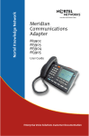
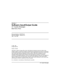
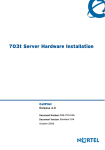
Title page
Nortel Communication Server 1000
Nortel Communication Server 1000 Release 4.5
Communication Server 1000S
Overview
Document Number: 553-3031-010
Document Release: Standard 3.00
Date: August 2005
Year Publish FCC TM
Copyright © Nortel Networks Limited 2005
All Rights Reserved
Produced in Canada
Information is subject to change without notice. Nortel Networks reserves the right to make changes in design
or components as progress in engineering and manufacturing may warrant.
Nortel, Nortel (Logo), the Globemark, This is the Way, This is Nortel (Design mark), SL-1, Meridian 1, and
Succession are trademarks of Nortel Networks.
4
Page 3 of 44
Revision history
August 2005
Standard 3.00. This document is up-issued to support Communication
Server 1000 Release 4.5.
September 2004
Standard 2.00. This document is up-issued for Communication Server 1000
Release 4.0.
October 2003
Standard 1.00. This document is a new NTP for Succession 3.0. It was created
to support a restructuring of the Documentation Library. This document
contains information previously contained in the following legacy document,
now retired: System Overview (553-3023-010).
Communication Server 1000S
Overview
Page 4 of 44
Revision history
553-3031-010
Standard
3.00
August 2005
6
Page 5 of 44
Contents
About this document . . . . . . . . . . . . . . . . . . . . . . .
7
Subject .. . . . . . . . . . . . . . . . . . . . . . . . . . . . . . . . . . . . . . . . . . . . . . . . .
7
Applicable systems . . . . . . . . . . . . . . . . . . . . . . . . . . . . . . . . . . . . . . . .
8
Intended audience . . . . . . . . . . . . . . . . . . . . . . . . . . . . . . . . . . . . . . . . .
8
Conventions .. . . . . . . . . . . . . . . . . . . . . . . . . . . . . . . . . . . . . . . . . . . . .
8
Related information .. . . . . . . . . . . . . . . . . . . . . . . . . . . . . . . . . . . . . . .
8
Description and features . . . . . . . . . . . . . . . . . . . .
11
Contents .. . . . . . . . . . . . . . . . . . . . . . . . . . . . . . . . . . . . . . . . . . . . . . . .
11
Introduction . . . . . . . . . . . . . . . . . . . . . . . . . . . . . . . . . . . . . . . . . . . . . .
Migrating to an IP telephony network . . . . . . . . . . . . . . . . . . . . . . .
12
12
Features . . . . . . . . . . . . . . . . . . . . . . . . . . . . . . . . . . . . . . . . . . . . . . . . .
Capacity . . . . . . . . . . . . . . . . . . . . . . . . . . . . . . . . . . . . . . . . . . . . . .
Flexibility and redundancy . . . . . . . . . . . . . . . . . . . . . . . . . . . . . . . .
Software applications . . . . . . . . . . . . . . . . . . . . . . . . . . . . . . . . . . . .
Enhanced system management .. . . . . . . . . . . . . . . . . . . . . . . . . . . .
Terminal equipment . . . . . . . . . . . . . . . . . . . . . . . . . . . . . . . . . . . . .
Interworking/Interoperability . . . . . . . . . . . . . . . . . . . . . . . . . . . . . .
14
14
14
15
18
19
22
System architecture . . . . . . . . . . . . . . . . . . . . . . . .
23
Contents .. . . . . . . . . . . . . . . . . . . . . . . . . . . . . . . . . . . . . . . . . . . . . . . .
23
Hardware architecture . . . . . . . . . . . . . . . . . . . . . . . . . . . . . . . . . . . . . .
Call Server . . . . . . . . . . . . . . . . . . . . . . . . . . . . . . . . . . . . . . . . . . . .
Small System Controller card .. . . . . . . . . . . . . . . . . . . . . . . . . . . . .
Signaling Server . . . . . . . . . . . . . . . . . . . . . . . . . . . . . . . . . . . . . . . .
24
26
26
27
Communication Server 1000S
Overview
Page 6 of 44
553-3031-010
Contents
Media Gateway 1000S . . . . . . . . . . . . . . . . . . . . . . . . . . . . . . . . . . .
Ethernet switch (customer-supplied) . . . . . . . . . . . . . . . . . . . . . . . .
Power over LAN (optional) . . . . . . . . . . . . . . . . . . . . . . . . . . . . . . .
Infrastructure . . . . . . . . . . . . . . . . . . . . . . . . . . . . . . . . . . . . . . . . . .
29
30
30
30
Software architecture . . . . . . . . . . . . . . . . . . . . . . . . . . . . . . . . . . . . . .
Centralized Automatic Software Upgrade . . . . . . . . . . . . . . . . . . . .
Centralized upgrade . . . . . . . . . . . . . . . . . . . . . . . . . . . . . . . . . . . . .
Centralized patching . . . . . . . . . . . . . . . . . . . . . . . . . . . . . . . . . . . .
File uploading . . . . . . . . . . . . . . . . . . . . . . . . . . . . . . . . . . . . . . . . .
Patching implementation . . . . . . . . . . . . . . . . . . . . . . . . . . . . . . . . .
31
31
31
31
31
31
Configuration options . . . . . . . . . . . . . . . . . . . . . .
33
Contents . . . . . . . . . . . . . . . . . . . . . . . . . . . . . . . . . . . . . . . . . . . . . . . .
33
Introduction .. . . . . . . . . . . . . . . . . . . . . . . . . . . . . . . . . . . . . . . . . . . . .
33
Single campus deployment . . . . . . . . . . . . . . . . . . . . . . . . . . . . . . . . . .
35
Multiple buildings in a campus .. . . . . . . . . . . . . . . . . . . . . . . . . . . . . .
37
Multiple sites .. . . . . . . . . . . . . . . . . . . . . . . . . . . . . . . . . . . . . . . . . . . .
Routing to and from local branch offices .. . . . . . . . . . . . . . . . . . . .
38
39
Distributed Call Servers . . . . . . . . . . . . . . . . . . . . . . . . . . . . . . . . . . . .
40
Reliability strategies . . . . . . . . . . . . . . . . . . . . . . . . . . . . . . . . . . . . . . .
IP telephony node configuration . . . . . . . . . . . . . . . . . . . . . . . . . . .
41
43
Standard 3.00
August 2005
10
Page 7 of 44
About this document
This document is a global document. Contact your system supplier or your
Nortel representative to verify that the hardware and software described are
supported in your area.
Subject
WARNING
Before a CS 1000S system can be installed, a network
assessment must be performed and the network must be
VoIP-ready.
If the minimum VoIP network requirements are not met,
the system will not operate properly.
For information on the minimum VoIP network
requirements and converging a data network with VoIP,
refer to Data Networking for Voice over IP
(553-3001-160).
This document provides an overview of the general design and features of the
CS 1000S system.
Note on legacy products and releases
This NTP contains information about systems, components, and features that
are compatible with Nortel Communication Server 1000 Release 4.5
software. For more information on legacy products and releases, click the
Communication Server 1000S
Overview
Page 8 of 44
About this document
Technical Documentation link under Support & Training on the Nortel
home page:
www.nortel.com
Applicable systems
This document applies to the Communication Server 1000S (CS 1000S)
system.
Intended audience
This document is intended for individuals responsible for the sale,
acquisition, planning, or installation of a CS 1000S system.
Conventions
In this document, the CS 1000S system is referred to generically as “system.”
Related information
This section lists information sources that relate to this document.
NTPs
The following NTPs are referenced in this document:
553-3031-010
•
Data Networking for Voice over IP (553-3001-160)
•
IP Peer Networking: Installation and Configuration (553-3001-213)
•
Branch Office: Installation and Configuration (553-3001-214)
•
WLAN IP Telephony: Installation and Configuration (553-3001-304)
•
Integrated Conference Bridge: Service Implementation Guide
(553-3001-358)
•
Hospitality Integrated Voice Services: Service Implementation Guide
(553-3001-359)
•
Integrated Recorded Announcer: Service Implementation Guide
(553-3001-360)
Standard 3.00
August 2005
About this document
Page 9 of 44
•
Integrated Call Director: Service Implementation Guide (553-3001-361)
•
Integrated Call Assistant: Service Implementation Guide
(553-3001-362)
•
IP Line: Description, Installation, and Operation (553-3001-365)
•
Telephones and Consoles: Description, Installation, and Operation
(553-3001-367)
•
IP Phones: Description, Installation, and Operation (553-3001-368)
•
DECT: Description, Planning, Installation, and Operation
(553-3001-370)
Online
To access Nortel documentation online, click the Technical Documentation
link under Support & Training on the Nortel home page:
www.nortel.com
CD-ROM
To obtain Nortel documentation on CD-ROM, contact your Nortel customer
representative.
Communication Server 1000S
Overview
Page 10 of 44
553-3031-010
About this document
Standard 3.00
August 2005
22
Page 11 of 44
Description and features
Contents
This section contains information on the following topics:
Introduction . . . . . . . . . . . . . . . . . . . . . . . . . . . . . . . . . . . . . . . . . . . . . .
Migrating to an IP telephony network . . . . . . . . . . . . . . . . . . . . . . .
12
12
Features . . . . . . . . . . . . . . . . . . . . . . . . . . . . . . . . . . . . . . . . . . . . . . . . .
Capacity . . . . . . . . . . . . . . . . . . . . . . . . . . . . . . . . . . . . . . . . . . . . . .
Flexibility and redundancy . . . . . . . . . . . . . . . . . . . . . . . . . . . . . . . .
Software applications . . . . . . . . . . . . . . . . . . . . . . . . . . . . . . . . . . . .
Enhanced system management. . . . . . . . . . . . . . . . . . . . . . . . . . . . .
Terminal equipment . . . . . . . . . . . . . . . . . . . . . . . . . . . . . . . . . . . . .
Interworking/Interoperability . . . . . . . . . . . . . . . . . . . . . . . . . . . . . .
14
14
14
15
18
19
22
Communication Server 1000S
Overview
Page 12 of 44
Description and features
Introduction
WARNING
Before a CS 1000S system can be installed, a network
assessment must be performed and the network must be
VoIP-ready.
If the minimum VoIP network requirements are not met,
the system will not operate properly.
For information on the minimum VoIP network
requirements and converging a data network with VoIP,
refer to Data Networking for Voice over IP
(553-3001-160).
The CS 1000S is an IP PBX that was introduced to address the increasing
demand for Voice over IP (VoIP) and support the convergence of voice and
data networks. In addition to supporting powerful new IP features, including
Session Initiation Protocol (SIP), the CS 1000S provides continued support
of the traditional Meridian suite of features.
CS 1000S expands the system’s capabilities to leverage the flexibility of IP
WANs. It provides seamless network integration, simplified management,
greater flexibility in network deployment, and reduced costs for supporting
an increasingly distributed global user community.
CS 1000S is more than an IP PBX. It is the architecture that evolves, using
open standards, to deliver future Advanced Applications, Interactive
Multimedia Services, Integrated Desktops, and Management Services.
Migrating to an IP telephony network
CS 1000S architecture provides an IP-based alternative to traditional
Meridian 1 architecture. It is designed to enable IP-based communication
models while protecting the investment of Meridian 1 end users as they
migrate to new technologies. Figure 1 illustrates the key components of this
architecture.
553-3031-010
Standard 3.00
August 2005
Description and features
Page 13 of 44
Figure 1
Software architecture for telephony
Telephony
Feature
Proccessing
Meridian 1
CS 1000
Circuit Switching Manager
Digital
Analog
Telephones
Telephones
PSTN/
ISDN
Virtual Connection Manager
Other
TDM
Circuit Switching Equipment
Media
BW
control
IP
Phone
control
H.323
XML
SIP ...
Interface for IP-Based Devices
Internet Enabling
553-AAA2129
Telephony Feature Processing is based on the existing Meridian 1 Call
Processing software and provides industry-leading feature capabilities.
The Virtual Connection Manager allows IP-based devices that are registered
with the Call Server to access the same feature capabilities as existing
telephony devices. In this way, the Meridian 1 feature set is made available
to evolving IP devices and soft clients, and is the switching foundation of
CS 1000S. In addition to access to the Telephony Feature Processing of a Call
Server, devices can also access other services in the network, such as XML
and IM. The Virtual Connection Manager supports IP Phones and a wider
suite of devices and services.
Communication Server 1000S
Overview
Page 14 of 44
Description and features
The Circuit Switching Manager evolved from Meridian 1 software. This
migration strategy enables Telephony Feature Processing for future releases
of CS 1000S to control existing Meridian 1 hardware components. In this
way, the investment in existing equipment is preserved while new capabilities
are added at a managed pace.
Features
Key features of the CS 1000S system are as follows:
•
capacity
•
flexibility and redundancy
•
software applications
•
enhanced system management
•
terminal equipment
•
interworking/interoperability
Capacity
The CS 1000S Call Server can support up to four Media Gateway 1000S
(MG 1000S) systems, and each MG 1000S can support a Media
Gateway 1000S Expander (MG 1000S Expander).
The MG 1000S has a Small System Controller (SSC) card and has four
available slots for flexible configurations of line and trunk cards.
The Call Server can support up to 1000 IP Phones.
Flexibility and redundancy
The CS 1000S can be deployed in many flexible configurations in a LAN or
WAN environment. The system can be deployed in a single location, multiple
buildings in a campus setting, or a network of multiple locations with
distributed Call Servers or branch offices.
553-3031-010
Standard 3.00
August 2005
Description and features
Page 15 of 44
The CS 1000S provides a number of capabilities to ensure that telephony is
available in the event of equipment failure at a site. CS 1000S provides the
following component redundancy:
•
Call Server with automatic database distribution
•
Signaling Server software, including H.323 Gateway and IP Phone
software
•
H.323 Gatekeeper
•
H.323 Gateway interface to Gatekeeper
•
Campus-distributed MG 1000S in Survival Mode
Refer to “Configuration options” on page 33 for more information on system
deployment and reliability strategies.
Software applications
CS 1000S supports a broad suite of applications, including the following:
•
CallPilot applications
•
Symposium Call Center Server
•
Nortel Integrated Recorded Announcer
•
Nortel Remote Gateway 9150
•
Nortel Integrated Call Assistant
•
Nortel Integrated Conference Bridge
•
Nortel Integrated Call Director
•
Nortel Hospitality Integrated Voice Services
CallPilot applications
CallPilot is a multimedia messaging system that offers a single solution for
managing information, including the following:
•
voice, fax, and e-mail messages
•
telephone calls (including conference)
•
calendars
Communication Server 1000S
Overview
Page 16 of 44
Description and features
•
directories
•
call logs
CallPilot 2.0
CallPilot 2.0 includes the 501t and the 1002rp messaging platforms as
replacements for the existing standalone platforms.
CallPilot 1.5 Mini
CallPilot 1.5 Mini is a less expensive, embedded messaging stand-alone
platform that provides Unified Messaging and base Voice Messaging
capabilities in both Meridian 1 and CS 1000S switching environments.
Symposium Call Center Server
Symposium Call Center Server (SCCS) offers a suite of applications that
includes call processing and agent handling, extensive management and
reporting capabilities, third-party application interfaces, and real-time
displays for supervisors and managers. For further information, see the
Symposium Call Centre Server documentation.
Nortel Integrated Recorded Announcer
Nortel Integrated Recorded Announcer enables the user to manage recorded
announcements using a Browser User Interface (BUI), a Telephone User
Interface (TUI), or a text-based user interface. For further information, see
Integrated Recorded Announcer: Service Implementation Guide
(553-3001-360).
Nortel Remote Gateway 9150
Nortel Remote Gateway 9150 enables remote employees of central offices to
access CS 1000S features and functionality using an IP WAN. The Remote
Gateway 9150 unit installs at the remote site and communicates with the
central site using a 10BaseT Ethernet or ISDN Basic Rate Interface (BRI)
connection. It uses VoIP technology to route voice and signaling packets
between the remote office site and the CS 1000S main site, enabling seamless
integration.
553-3031-010
Standard 3.00
August 2005
Description and features
Page 17 of 44
The VoIP features automatically switch from the IP network to the PSTN,
when voice Quality of Service (QOS) falls below a pre-determined threshold.
IP Telephony resumes when QOS levels return to an acceptable level.
Remote Gateway 9150 supports a maximum of 32 digital telephones.
For further information, see Remote Gateway 9150: Installation and
Administration Guide (555-8421-215).
Nortel Integrated Call Assistant
The Nortel Integrated Call Assistant can route calls to desired destinations
after a series of greetings are played. The destination is based on the caller’s
telephone keypad strokes. For further information, see Integrated Call
Assistant: Service Implementation Guide (553-3001-362).
Nortel Integrated Conference Bridge
The Nortel Integrated Conference Bridge enables a user to schedule and
manage conference bridges using a Browser User Interface (BUI) or a
Telephone User Interface (TUI). These interfaces enable a user to schedule
and configure one-time and recurrent conferences. For further information,
see Integrated Conference Bridge: Service Implementation Guide
(553-3001-358).
Nortel Integrated Call Director
The Nortel Integrated Call Director enables users to automatically forward
incoming telephone calls to another number, such as a cellular or home
telephone. The Integrated Call Director continues to forward the call until the
call is answered, or all the options are exhausted. For further information, see
Integrated Call Director: Service Implementation Guide (553-3001-361).
Nortel Hospitality Integrated Voice Services
Nortel Hospitality Integrated Voice Services provide the hospitality services
of Automatic Wake Up (AWU) and Do Not Disturb (DND). The guest dials
an access DN and follows instructions until a confirmation message plays to
activate a feature. For further information, see Hospitality Integrated Voice
Services: Service Implementation Guide (553-3001-359).
Communication Server 1000S
Overview
Page 18 of 44
Description and features
Enhanced system management
CS 1000S supports a suite of value-added management capabilities for
multiple systems that reduces a customer’s total cost of ownership. These
include Optivity Telephony Manager (OTM) and Element Manager.
Optivity Telephony Manager
Optivity Telephony Manager (OTM) provides management simplicity and
flexible control. OTM features include the following:
•
Lightweight Directory Access Protocol (LDAP) directory integration
•
station administration
•
call accounting
•
call tracking
•
traffic analysis
•
maintenance
•
alarm management
•
centralized management
•
multi-user capability
•
web-based functionality
•
customizable reporting
•
import/export utility
•
scheduled tasks
•
disaster recovery tools
These features save time and facilities costs, simplifying the management of
a complex network.
Element Manager
Element Manager is a simple and user-friendly web-based interface that
supports a broad range of system management tasks, including:
•
553-3031-010
configuration and maintenance of IP Peer and IP telephony features
Standard 3.00
August 2005
Description and features
Page 19 of 44
•
configuration and maintenance of traditional routes and trunks
•
configuration and maintenance of numbering plans
•
configuration of Call Server data blocks (such as configuration data,
customer data, Common Equipment data, D-channels)
•
maintenance commands, system status inquiries, backup and restore
functions
•
software download, patch download, patch activation
Element Manager has many features to help administrators manage systems
with greater efficiency. Examples are as follows:
•
Web pages provide a single point-of-access to parameters that were
traditionally available through multiple overlays.
•
Parameters are presented in logical groups to increase ease-of-use and
speed-of-access.
•
The "hide or show information" option enables administrators to see
information that relates directly to the task at hand.
•
Full-text descriptions of parameters and acronyms help administrators
reduce configuration errors.
•
Configuration screens offer pre-selected defaults, drop-down lists,
checkboxes, and range values to simplify response selection.
The Element Manager web server resides on the Signaling Server and can be
accessed directly through a web browser or Optivity Telephony Manager
(OTM). The OTM navigator includes integrated links to each network system
and their respective instances of Element Manager.
Terminal equipment
The CS 1000S supports the following terminal equipment:
•
IP Phones
•
802.11 Wireless LAN
•
wireless telephones
•
digital telephones
Communication Server 1000S
Overview
Page 20 of 44
Description and features
•
IP Phone adapter
•
analog telephones and devices
•
attendant consoles
For further information on analog and digital telephones, see Telephones and
Consoles: Description, Installation, and Operation (553-3001-367). See
IP Phones: Description, Installation, and Operation (553-3001-368) for
information on IP Phones.
IP Phones
IP Phones provide the desktop clients for CS 1000S IP Telephony. The
functionality and call features of these IP Phones are similar to that of a
standard digital telephone, such as the M2616. The CS 1000S system
supports the following IP Phones:
•
Nortel IP Phone 2001
•
Nortel IP Phone 2002
•
Nortel IP Phone 2004
•
Nortel IP Phone 2007
•
Nortel IP Audio Conference Phone 2033
•
Nortel IP Softphone 2050
•
Nortel Mobile Voice Client (MVC) 2050
•
WLAN Handsets 2210/2211
802.11 Wireless LAN
CS 1000S supports the 802.11 Wireless LAN. The 802.11 Wireless LAN
requires an H.323 Symbol Wireless client terminal.
Wireless telephones
CS 1000S supports 802.11 Wireless IP Gateway, the WLAN IP Telephony
Manager 2245 for the WLAN Handsets 2210/221, and Nortel Integrated
DECT (DECT) systems.
553-3031-010
Standard 3.00
August 2005
Description and features
Page 21 of 44
802.11 Wireless IP Gateway
The e-mobility Meridian Gateway supports communication between the
circuit-switched telephony network and the H.323 Wireless IP terminals on a
customer’s corporate IP network. For further information, see WLAN IP
Telephony: Installation and Configuration (553-3001-304).
DECT
The DECT system is an application that enables users to move freely about
their work sites using wireless handsets, and keep in communication with
end-users and suppliers. Missed calls are reduced and employee productivity
is increased due to quick employee response times and multi-tasking
flexibility. For further information, see DECT: Description, Planning,
Installation, and Operation (553-3001-370).
Digital telephones
The CS 1000S system supports a wide range of Digital Line cards that
provide global telecommunications market interfaces.
The CS 1000S system supports the M3900 series Meridian Digital
Telephones. This includes the M3901 Entry Level Telephone, the M3902
Basic Telephone, the M3903 Enhanced Telephone, the M3904 Professional
Telephone, and the M3905 Call Center Telephone.
In conformance with the Evergreen policy, the CS 1000S system also
supports other digital telephones, including the M2006, M2008, M2008HF,
M2616, M2016S, M2216ACD, and M2317 digital telephones.
IP Phone adapter
The CS 1000S system supports the IP Phone adapter package, for the M26xx
and M39xx telephones. The IP Phone adapter package is intended for local
deployment and does not support analog PSTN fallback.
Analog telephones and devices
The CS 1000S system supports a wide range of Analog Line cards that
provide analog (500/2500-type) telephones and T.38 Fax interfaces.
Communication Server 1000S
Overview
Page 22 of 44
Description and features
Attendant consoles
The CS 1000S system supports an Attendant PC software console and the
M2250 attendant console.
The Attendant PC software enables users to perform attendant console and
call processing functions on a Windows® PC using a mouse or keyboard.
The Attendant PC combines the call-processing power of the M2250
attendant console with the information-processing and storage power of a PC,
enhancing attendant services.
Interworking/Interoperability
The CS 1000S uses the standard H.323 protocol to support interworking with
other vendors. Interoperability testing is required to determine which
products are compatible with CS 1000S systems. A number of products are
supported as part of the development, including the following:
•
BCM 2.5+
•
CS 1000M using an IP Trunk 2.x up-issue
Interworking with Nortel’s CS 1000M and BCM products is provided to
enable enterprise networks to smoothly migrate from traditional TDM-based
PBXs to IP-based telephony products.
553-3031-010
Standard 3.00
August 2005
32
Page 23 of 44
System architecture
Contents
This section contains information on the following topics:
Hardware architecture . . . . . . . . . . . . . . . . . . . . . . . . . . . . . . . . . . . . . .
Call Server . . . . . . . . . . . . . . . . . . . . . . . . . . . . . . . . . . . . . . . . . . . .
Small System Controller card. . . . . . . . . . . . . . . . . . . . . . . . . . . . . .
Signaling Server . . . . . . . . . . . . . . . . . . . . . . . . . . . . . . . . . . . . . . . .
Media Gateway 1000S . . . . . . . . . . . . . . . . . . . . . . . . . . . . . . . . . . .
Ethernet switch (customer-supplied) . . . . . . . . . . . . . . . . . . . . . . . .
Power over LAN (optional) . . . . . . . . . . . . . . . . . . . . . . . . . . . . . . .
Infrastructure . . . . . . . . . . . . . . . . . . . . . . . . . . . . . . . . . . . . . . . . . .
24
26
26
27
29
30
30
30
Software architecture. . . . . . . . . . . . . . . . . . . . . . . . . . . . . . . . . . . . . . .
Centralized Automatic Software Upgrade . . . . . . . . . . . . . . . . . . . .
Centralized upgrade . . . . . . . . . . . . . . . . . . . . . . . . . . . . . . . . . . . . .
Centralized patching. . . . . . . . . . . . . . . . . . . . . . . . . . . . . . . . . . . . .
File uploading. . . . . . . . . . . . . . . . . . . . . . . . . . . . . . . . . . . . . . . . . .
Patching implementation . . . . . . . . . . . . . . . . . . . . . . . . . . . . . . . . .
31
31
31
31
31
31
Communication Server 1000S
Overview
Page 24 of 44
System architecture
Hardware architecture
A typical CS 1000S system consists of the following major hardware
components:
•
NTDU30 Call Server
•
NTDU27 Signaling Server
•
NTDU14 Media Gateway 1000S (MG 1000S)
•
NTDU15 Media Gateway 1000S Expander (MG 1000S Expander)
•
IP Phones
•
customer-supplied Ethernet Layer 2 switch
•
Power over LAN unit (optional)
Figure 2 on page 25 shows the major hardware components installed in a
customer-supplied 19-inch rack.
553-3031-010
Standard 3.00
August 2005
System architecture
Page 25 of 44
Figure 2
CS 1000S components in a rack
NTDU30 Call Server
NTDU27 Signaling Server
NTDU14 Media Gateway 1000S
NTDU15 Media Gateway
1000S Expander
Customer Supplied
Ethernet Switch
Power over LAN unit (optional)
553-AAA2256
Communication Server 1000S
Overview
Page 26 of 44
System architecture
Call Server
The Call Server provides telephony services, such as call processing, and
supports trunking features. It also acts as a database server for
synchronization of configuration information with all MG 1000S systems.
A CS 1000S system can control a maximum of four MG 1000S systems and
Expanders.
A CS 1000S system with one Call Server supports up to 1000 IP Phones. You
can network a CS 1000S system with other CS 1000S systems to support
larger numbers of IP Phones.
Small System Controller card
The NTDK20 Small System Controller (SSC) card in the Call Server is the
primary system processor. It controls the telephony services and call
processing. Each MG 1000S is also equipped with an SSC card.
The Call Server SSC controls the call-processing features of IP Phones and
trunk interfaces when in normal mode of operation.
The Call Server SSC synchronizes the configuration information on all
MG 1000S SSC cards. The configuration data on all MG 1000S SSC cards
always exactly matches the Call Server SSC configuration data.
The card’s Security Device enables the activation of features assigned to the
system, through the use of a series of keycodes.
Media Gateway 1000S SSC card
The SSC card in the MG 1000S controls the MG 1000S interface and
application cards, and acts as a survivable call processor. All MG 1000S SSC
cards are synchronized with the call processing on the Call Server SSC card.
This synchronization enables an MG 1000S SSC card to take over local call
processing if the primary Call Server fails to respond.
If the Call Server fails to respond, each MG 1000S SSC can become its own
independent call processor. This means that in the event of Call Server failure,
one MG 1000S SSC does not act as a Call Server for the rest of the system;
they are all independent.
553-3031-010
Standard 3.00
August 2005
System architecture
Page 27 of 44
Signaling Server
CS 1000S systems use a Signaling Server. The Signaling Server is an
industry-standard, PC-based server that provides a central processor to drive
H.323 and Session Initiation Protocol (SIP) signaling for IP Phones and
IP Peer Networking. It provides signaling interfaces to the IP network using
software components that operate on the VxWorks™ real-time operating
system.
The Signaling Server has both an ELAN and TLAN network interface. The
Signaling Server communicates with the Call Server through the ELAN
subnet.
The Signaling Server is mounted in a 19-inch rack. The Signaling Server can
be installed in a load-sharing redundant configuration for higher scalability
and reliability.
The following software components operate on the Signaling Server:
•
Terminal Proxy Server
•
SIP/H.323 Signaling Gateways
•
Network Routing Service
•
Element Manager
All the software elements can coexist on one Signaling Server or reside
individually on separate Signaling Servers, depending on traffic and
redundancy requirements for each element.
For more information about H.323 and SIP Trunking, refer to IP Peer
Networking: Installation and Configuration (553-3001-213).
Communication Server 1000S
Overview
Page 28 of 44
System architecture
Terminal Proxy Server
The Terminal Proxy Server (TPS) acts as a signaling gateway between the IP
Phones and the Call Server using the UNIStim protocol. It performs the
following functions:
•
converts the IP Phone UNIStim messages into messages the Call Server
can interpret
•
allows IP Phones to access telephony features provided by the Call
Server
The TPS also controls the IP Phone registration.
SIP/H.323 Signaling Gateways
SIP/H.323 Signaling Gateways are software components configured on
virtual loops, similar to IP Phones. SIP/H.323 Signaling Gateways bridge
existing call processing features and the IP network. They also enable access
to the routing and features in the MCDN feature set.
Note 1: The SIP/H.323 Signaling Gateway must register with the
Network Routing Service (NRS).
Note 2: Virtual TNs enable you to configure service data without
hardwiring IP Phones to the CS 1000S system. Virtual TNs are
configured in LD 97.
To support IP Peer Networking, dual Call Servers in a CS 1000S must be
associated with Signaling Servers that run SIP/H.323 Signaling Gateway
software. The number of Signaling Servers required depends on the capacity
and level of redundancy required.
Network Routing Service
The NRS application provides network-based routing, combining the
following into a single application:
553-3031-010
•
H.323 Gatekeeper — The H.323 Gatekeeper provides central dialing
plan management and routing for H.323-based endpoints and gateways.
•
SIP Redirect Server — The SIP Redirect Server provides central
dialing plan management and routing for SIP-based endpoints and
gateways.
Standard 3.00
August 2005
System architecture
Page 29 of 44
•
NRS Database — The NRS database stores the central dialing plan in
XML format for both the SIP Redirect Server and the H.323 Gatekeeper.
The SIP Redirect Server and H.323 Gatekeeper both access this common
endpoint and gateway database.
•
Network Connect Server (NCS) — The NCS is used only for Media
Gateway 1000B (MG 1000B) and Virtual Office solutions.
•
NRS Manager web interface — The NRS provides its own web
interface to configure the SIP Redirect Server, the H.323 Gatekeeper,
and the NCS.
The NRS application provides routing services to both H.323- and
SIP-compliant devices. The H.323 Gatekeeper can be configured to support
H.323 routing services, while the SIP Redirect Server can be configured to
support SIP routing services.The H.323 Gatekeeper and the SIP Redirect
Server can reside on the same Signaling Server.
Each system in an IP Peer network must register to the NRS. The NRS
software identifies the IP addresses of systems based on the network-wide
numbering plan. NRS registration eliminates the need for manual
configuration of IP addresses and numbering plan information at every site.
Element Manager
Element Manager is a software application that provides a web interface to
configure and maintain system components, including the Signaling Server.
Single web pages provide access to information traditionally spread into
multiple overlays.
For more information on the Element Manager application, see “Element
Manager” on page 18.
Media Gateway 1000S
The MG 1000S holds Intelligent Peripheral Equipment (IPE) cards and
application cards. In a normal operational state, the Call Server controls the
MG 1000S. The MG 1000S processor provides low-level control of the
interface cards installed in the MG 1000S slots, and communicates with the
Call Server for feature operation.
Communication Server 1000S
Overview
Page 30 of 44
System architecture
The MG 1000S supports a Small System Controller (SSC) card and four slots
for flexible configurations of line, trunk, and application cards.
Note: You can configure the SSC in the MG 1000S for survivability to
assume local call processing if the Call Server cannot be accessed. If the
MG 1000S is not configured as survivable, then the MG 1000S is
out-of-service until the Call Server is again accessible.
Voice Gateway Media Cards are installed in the MG 1000S. A Voice
Gateway Media Card provides transcoding between IP and circuit-switched
protocol.
Each MG 1000S can support one MG 1000S Expander.
Ethernet switch (customer-supplied)
The customer-supplied Layer 2 Ethernet switch transmits data packets to
interconnected Ethernet-attached devices. The switch directs the data only to
the targeted device, rather than to all attached devices. See Data Networking
for Voice over IP (553-3001-160) for details.
Power over LAN (optional)
An optional Power over LAN unit adds power and data communication over
standard Category 5 LAN drops for powering IP Phones. The Power over
LAN unit eliminates the need to connect each telephone to an AC power
outlet. This saves in desktop wiring and enables the use of a centralized
Uninterruptible Power Supply (UPS) for power backups.
Infrastructure
Various infrastructure components are required to support VoIP. These
components include switches, routers, and MG 1000S. The data network
infrastructure’s engineering and provisioning is critical to achieve
satisfactory telephony voice quality. For more information, see Data
Networking for Voice over IP (553-3001-160).
553-3031-010
Standard 3.00
August 2005
System architecture
Page 31 of 44
Software architecture
Centralized Automatic Software Upgrade
Centralized Automatic Software Upgrade allows a new version of software to
be automatically loaded on the MG 1000S after the Call Server software is
upgraded. To reduce service impact, a sequential upgrade mode upgrades
only one MG 1000S at a time.
Centralized upgrade
Centralized upgrade enables the IP telephony components (Voice Gateway
Media Cards) to be upgraded from the Element Manager interface. The
Element Manager host, the Signaling Server, is a file server for software
upgrade files for the Voice Gateway Media Cards. IP Phones also
automatically upgrade from a centralized file location (their TPS).
Centralized patching
Centralized patching enables IP telephony components, the Call Server, and
MG 1000S systems, to be patched from a central location through Element
Manager.
File uploading
File uploading enables software upgrade files and patches to be uploaded to
the Element Manager host, the Signaling Server, for centralized upgrading or
centralized patching. The file is uploaded from the management PC (web
browser) to the Element Manager host (web server).
Patching implementation
The Call Server, MG 1000S, Signaling Server, and the Voice Gateway Media
Cards are patchable. Installing a patch enables a fix to be delivered, without
requiring a new version of software.
Communication Server 1000S
Overview
Page 32 of 44
553-3031-010
System architecture
Standard 3.00
August 2005
44
Page 33 of 44
Configuration options
Contents
This section contains information on the following topics:
Introduction . . . . . . . . . . . . . . . . . . . . . . . . . . . . . . . . . . . . . . . . . . . . . .
33
Single campus deployment . . . . . . . . . . . . . . . . . . . . . . . . . . . . . . . . . .
35
Multiple buildings in a campus . . . . . . . . . . . . . . . . . . . . . . . . . . . . . . .
37
Multiple sites . . . . . . . . . . . . . . . . . . . . . . . . . . . . . . . . . . . . . . . . . . . . .
Routing to and from local branch offices . . . . . . . . . . . . . . . . . . . . .
38
39
Distributed Call Servers . . . . . . . . . . . . . . . . . . . . . . . . . . . . . . . . . . . .
40
Reliability strategies . . . . . . . . . . . . . . . . . . . . . . . . . . . . . . . . . . . . . . .
IP telephony node configuration . . . . . . . . . . . . . . . . . . . . . . . . . . .
41
43
Introduction
The IP-distributed architecture of CS 1000S offers the benefits of location
flexibility for system components. The architecture also provides wiring
control and simplification of space planning, system management, and
databases.
CS 1000S bridges the circuit-switched PBX and the IP network, or it can
operate in an IP-only network. This consolidation of network traffic
simplifies the task of managing communication to a single, efficient IP
network. End users can deploy the CS 1000S in many flexible configurations
Communication Server 1000S
Overview
Page 34 of 44
Configuration options
in a LAN or WAN environment. Although different combinations are
possible, most installations fall into one of the following categories:
•
Single Site
— single building
— multiple buildings in a campus
•
Multiple Sites
— central Call Server with branch office users
— distributed Call Servers
For more information on system deployment options for the CS 1000S, refer
to Data Networking for Voice over IP (553-3001-160).
553-3031-010
Standard 3.00
August 2005
Configuration options
Page 35 of 44
Single campus deployment
Figure 3 shows an example of a single campus deployment and its
components.
Figure 3
Single campus deployments example
Call Server
Signaling Server
(Optionally Redundant)
Rest of World
PSTN
Media Gateway 1000S
Media Gateway
1000S Expander
IP Phones
Campus IP
Network
Survivable!
Survivable!
Network Management
802.11
Survivable!
Survivable!
Wireless
Access Point
Applications: Nortel Messaging Server 500, Symposium
553-AAA2130
Communication Server 1000S
Overview
Page 36 of 44
Configuration options
Note: You can configure the network for redundancy.
The single campus deployment example consists of the following:
•
Call Server
•
Signaling Server (optionally redundant)
•
up to four Media Gateways and four Media Gateway Expanders:
— can be configured to provide network redundancy
— provide a global suite of telephony trunks
553-3031-010
•
analog telephones (service for 2500 series telephones and fax)
•
digital telephones (service for Meridian 3900 telephones)
•
a switched Ethernet infrastructure
•
up to 1000 IP Phones
•
centralized management capability
•
other telephony applications
Standard 3.00
August 2005
Configuration options
Page 37 of 44
Multiple buildings in a campus
Figure 4 shows a CS 1000S system distributed across multiple buildings in a
campus setting. You can distribute MG 1000S systems and users across a
campus IP Network.
Figure 4
Multi-site deployment with centralized call processing
Campus Distributed
Media Gateway 1000S
Central Site
Media
Gateway 1000S
Call Server
Signaling Server
Optional
Signaling Server
Media Gateway 1000S
Trunks
Campus
IP Network
(Survivable)
Applications
Client
Trunks
Client
553-AAA2131
In Figure 4, the multi-site deployment with centralized call processing
consists of the following:
•
Call Server at the central site
•
Campus distributed MG 1000S
— optional Signaling Server
— MG 1000S (survivable)
— IP Phones configured and managed centrally from the central site
— Local trunks PSTN and 911 access.
Communication Server 1000S
Overview
Page 38 of 44
Configuration options
Multiple sites
Figure 5 shows a multi-site deployment with a central Call Server and a
branch office.
Figure 5
Central Call Server with branch office
Central Office
Branch Office
Call Server
Signaling Server
Signaling Server
Media Gateway 1000B
Nortel Messaging
Server 500
Media Gateway
1000S Expander
Campus IP
Network
Media Gateway 1000S
Rest of World
Campus IP
Network
Survivable!
Survivable!
Client
Survivable!
Survivable!
PSTN
Rest of World
553-AAA2132
The following apply to a multi-site deployment:
553-3031-010
•
The Call Server at the central site that provides call processing for the
main and branch offices.
•
The multi-site deployment can contain a branch office.
Standard 3.00
August 2005
Configuration options
Page 39 of 44
— Requires its own Signaling Server.
— MG 1000B in remote branch offices enables local PSTN and 911
access.
— IP Phones are configured and managed centrally from the main
office.
— The MG 1000B is survivable in the event of a WAN failure.
— You can configure up to 400 users for survivability.
— You can use the Signaling Server virtual trunking to the central site
for system management purposes.
Routing to and from local branch offices
IP Phone users can be located at a branch office that is equipped with an
MG 1000B Core. Call routing to the local MG 1000B Core is important,
especially if toll charges are applicable to calls from the central Call Server
controlling the IP Phone. The administrator can configure digit manipulation
for IP Phones that are located near a branch office, in order to select a branch
office that provides local PSTN access.
Calls from the PSTN to users within the network can be routed using either
(a) the various ESN numbering plan configurations, or (b) the Network
Number Resolution feature, based upon the Vacant Number Routing feature.
This enables small sites, such as a branch office, to require minimal
configuration to route calls through other Call Servers or the Gatekeeper. See
Branch Office: Installation and Configuration (553-3001-214).
Communication Server 1000S
Overview
Page 40 of 44
Configuration options
Distributed Call Servers
Distributed Call Servers are defined as multiple CS 1000S systems. Figure 6
shows an example of multi-site deployment with distributed Call Servers.
Figure 6
Distributed Call Servers
IP Peer Networking
Call Server
Signaling Server
Call Server
Signaling Server
Nortel Messaging
Server 500
Media Gateway
1000S Expander
IP WAN
Media Gateway 1000S
LAN
LAN
PSTN
Survivable!
Network VIA PRI
Survivable!
Call Server
Signaling Server
Survivable!
LAN
Tie Trunk (T1)
Survivable!
PSTN
PSTN
553-AAA2133
The multi-site deployment consists of the following peer sites:
553-3031-010
•
separate Call Servers that provide call processing for each site
•
networking supported with IP data network or circuit-switched (analog
or digital) trunks
Standard 3.00
August 2005
Configuration options
Page 41 of 44
•
full-featured networking between sites using IP Peer Networking and/or
TIE trunks
•
transparent to user at all sites
Reliability strategies
Communication reliability is critical to the operation of any business. A
number of capabilities are available in CS 1000S to ensure that telephony is
available when one or more of the following situations occur:
•
a hardware component fails
•
a software component fails
•
the IP network suffers an outage
The CS 1000S provides several levels of redundancy to ensure that the
telephony services can withstand single hardware and network failures.
CS 1000S provides the following component redundancy:
•
Call Server with automatic database distribution
•
Signaling Server software, including H.323 Gateway and IP Phone
software
•
H.323 Gatekeeper
•
H.323 Gateway interface to Gatekeeper
•
Campus-distributed MG 1000S in Survival Mode
You can provision a CS 1000S to provide the following component
redundancy:
•
If the Call Server is unavailable, you can configure MG 1000S systems
as survivable independent systems (automatic database
synchronization).
Note: If the MG 1000S is not configured as survivable, then it is out of
service until the Call Server is in service again.
•
If the Call Server is unavailable, the IP telephony node can re-register
with one MG 1000S specified as an Alternate Call Server.
Communication Server 1000S
Overview
Page 42 of 44
Configuration options
•
If the master (Leader) Signaling Server is unavailable, a Follower
Signaling Server becomes the IP Telephony node master.
•
Signaling Servers share telephone registrations (load-sharing).
•
If a virtual trunk is unavailable, virtual trunk redundancy occurs (that is,
the call-processing software selects an alternate route).
•
Signaling Servers can be configured for different types of redundancy for
their software components (for example, Alternate Gatekeeper, Failsafe
Gatekeeper).
•
If the Primary Gatekeeper is unavailable, you can configure an Alternate
Gatekeeper (automatic database synchronization).
•
If the Primary and Alternate Gatekeeper are unavailable, you can
configure a Failsafe Gatekeeper (at each Signaling Server).
Figure 7 on page 43 illustrates the handling of a network failure with
Survivable MG 1000S in place.
553-3031-010
Standard 3.00
August 2005
Configuration options
Page 43 of 44
Figure 7
Network failure with survivable MG 1000S systems
Call Server
Signaling Server (optionally redundant)
-Terminal Proxy Service (TPS)
-H.323 Gateway Signaling S/W
1. Call Server Database periodically
synchronized at Media Gateways
2. IP Campus Network Fails
3. Distributed Media Gateway enters
Survival mode
4. Voice Gateway Media Card registers
at Survival Media Gateway Controller Card
5. Operation resumes at Survivable site using
local cards only
6. Primary Call Server continues in normal mode for
reachable Media Gateways
WAN
Media Gateway
1000B
Survivable
Media Gateway
1000S
PSTN
553-AAA2134
IP telephony node configuration
An IP telephony node is a grouping of Voice Gateway Media Cards (and
Signaling Servers), regardless of the location of the Voice Gateway Media
Cards in the MG 1000S. Therefore, several MG 1000S can belong to the
same node. Alternately, each MG 1000S can have its own node.
Each IP telephony node can be configured with the IP address of an Alternate
Call Server, to which it registers if the Call Server is unavailable.
Note: The Alternate Call Server is an MG 1000S SSC that is configured
as survivable.
Communication Server 1000S
Overview
Page 44 of 44
Configuration options
The survivable MG 1000S (Alternate Call Server) IP address must be on the
same ELAN subnet as the Call Server. If the MG 1000S is on a physically
different subnet, such as in a different building, then you can use VLANs to
keep IP addresses on the same logical subnet. For further implementation
details, refer to Data Networking for Voice over IP (553-3001-160).
If there are different nodes in different MG 1000S, then the nodes can be
configured to register to different Alternate Call Servers. This concept is
desirable for optimizing system reliability to best deal with possible system
outages. Associate each IP telephony node with an appropriate (for example,
co-located) Alternate Call Server.
If the node IDs are configured using the guidelines for the ‘Enhanced
Redundancy for IP Line Nodes’ feature, then the IP Phones can register (if
needed) to an alternate node on an MG 1000S Expander. This further
improves the survivability of the IP Phones by allowing them to register to a
different node should a system outage occur on their primary node's
MG 1000S.
Refer to IP Line: Description, Installation, and Operation (553-3001-365)
for a description of the Enhanced Redundancy for IP Line Nodes feature.
553-3031-010
Standard 3.00
August 2005
Family Product Manual Contacts Copyright FCC notice Trademarks Document
number Product release Document release Date Publish
Nortel Communication Server 1000
Communication Server 1000S
Overview
Copyright © Nortel Networks Limited 2005
All Rights Reserved
Information is subject to change without notice.
Nortel Networks reserves the right to make changes in design
or components as progress in engineering and manufacturing
may warrant.
Nortel, Nortel (Logo), the Globemark, This is the Way, This is
Nortel (Design mark), SL-1, Meridian 1, and Succession are
trademarks of Nortel Networks.
Publication number: 553-3031-010
Document release: Standard 3.00
Date: August 2005
Produced in Canada