1
Cisco IOS LAN Switching
Configuration Guide
Release 12.4T
Americas Headquarters
Cisco Systems, Inc.
170 West Tasman Drive
San Jose, CA 95134-1706
USA
http://www.cisco.com
Tel: 408 526-4000
800 553-NETS (6387)
Fax: 408 527-0883
THE SPECIFICATIONS AND INFORMATION REGARDING THE PRODUCTS IN THIS MANUAL ARE SUBJECT TO CHANGE WITHOUT NOTICE. ALL
STATEMENTS, INFORMATION, AND RECOMMENDATIONS IN THIS MANUAL ARE BELIEVED TO BE ACCURATE BUT ARE PRESENTED WITHOUT
WARRANTY OF ANY KIND, EXPRESS OR IMPLIED. USERS MUST TAKE FULL RESPONSIBILITY FOR THEIR APPLICATION OF ANY PRODUCTS.
THE SOFTWARE LICENSE AND LIMITED WARRANTY FOR THE ACCOMPANYING PRODUCT ARE SET FORTH IN THE INFORMATION PACKET THAT
SHIPPED WITH THE PRODUCT AND ARE INCORPORATED HEREIN BY THIS REFERENCE. IF YOU ARE UNABLE TO LOCATE THE SOFTWARE LICENSE
OR LIMITED WARRANTY, CONTACT YOUR CISCO REPRESENTATIVE FOR A COPY.
The Cisco implementation of TCP header compression is an adaptation of a program developed by the University of California, Berkeley (UCB) as part of UCB’s public
domain version of the UNIX operating system. All rights reserved. Copyright © 1981, Regents of the University of California.
NOTWITHSTANDING ANY OTHER WARRANTY HEREIN, ALL DOCUMENT FILES AND SOFTWARE OF THESE SUPPLIERS ARE PROVIDED “AS IS” WITH
ALL FAULTS. CISCO AND THE ABOVE-NAMED SUPPLIERS DISCLAIM ALL WARRANTIES, EXPRESSED OR IMPLIED, INCLUDING, WITHOUT
LIMITATION, THOSE OF MERCHANTABILITY, FITNESS FOR A PARTICULAR PURPOSE AND NONINFRINGEMENT OR ARISING FROM A COURSE OF
DEALING, USAGE, OR TRADE PRACTICE.
IN NO EVENT SHALL CISCO OR ITS SUPPLIERS BE LIABLE FOR ANY INDIRECT, SPECIAL, CONSEQUENTIAL, OR INCIDENTAL DAMAGES, INCLUDING,
WITHOUT LIMITATION, LOST PROFITS OR LOSS OR DAMAGE TO DATA ARISING OUT OF THE USE OR INABILITY TO USE THIS MANUAL, EVEN IF CISCO
OR ITS SUPPLIERS HAVE BEEN ADVISED OF THE POSSIBILITY OF SUCH DAMAGES.
CCDE, CCENT, Cisco Eos, Cisco Lumin, Cisco Nexus, Cisco StadiumVision, Cisco TelePresence, the Cisco logo, DCE, and Welcome to the Human Network are
trademarks; Changing the Way We Work, Live, Play, and Learn and Cisco Store are service marks; and Access Registrar, Aironet, AsyncOS, Bringing the Meeting To You,
Catalyst, CCDA, CCDP, CCIE, CCIP, CCNA, CCNP, CCSP, CCVP, Cisco, the Cisco Certified Internetwork Expert logo, Cisco IOS, Cisco Press, Cisco Systems,
Cisco Systems Capital, the Cisco Systems logo, Cisco Unity, Collaboration Without Limitation, EtherFast, EtherSwitch, Event Center, Fast Step, Follow Me Browsing,
FormShare, GigaDrive, HomeLink, Internet Quotient, IOS, iPhone, iQ Expertise, the iQ logo, iQ Net Readiness Scorecard, iQuick Study, IronPort, the IronPort logo,
LightStream, Linksys, MediaTone, MeetingPlace, MeetingPlace Chime Sound, MGX, Networkers, Networking Academy, Network Registrar, PCNow, PIX, PowerPanels,
ProConnect, ScriptShare, SenderBase, SMARTnet, Spectrum Expert, StackWise, The Fastest Way to Increase Your Internet Quotient, TransPath, WebEx, and the
WebEx logo are registered trademarks of Cisco Systems, Inc. and/or its affiliates in the United States and certain other countries.
All other trademarks mentioned in this document or Website are the property of their respective owners. The use of the word partner does not imply a partnership relationship
between Cisco and any other company. (0807R)
Any Internet Protocol (IP) addresses used in this document are not intended to be actual addresses. Any examples, command display output, and figures included in the
document are shown for illustrative purposes only. Any use of actual IP addresses in illustrative content is unintentional and coincidental.
Cisco IOS LAN Switching Configuration Guide
© 2008 Cisco Systems, Inc. All rights reserved.
About Cisco IOS and Cisco IOS XE Software
Documentation
Last updated: August 6, 2008
This document describes the objectives, audience, conventions, and organization used in Cisco IOS and
Cisco IOS XE software documentation, collectively referred to in this document as Cisco IOS
documentation. Also included are resources for obtaining technical assistance, additional
documentation, and other information from Cisco. This document is organized into the following
sections:
•
Documentation Objectives, page i
•
Audience, page i
•
Documentation Conventions, page ii
•
Documentation Organization, page iii
•
Additional Resources and Documentation Feedback, page xi
Documentation Objectives
Cisco IOS documentation describes the tasks and commands available to configure and maintain Cisco
networking devices.
Audience
The Cisco IOS documentation set is i ntended for users who configure and maintain Cisco networking
devices (such as routers and switches) but who may not be familiar with the configuration and
maintenance tasks, the relationship among tasks, or the Cisco IOS commands necessary to perform
particular tasks. The Cisco IOS documentation set is also intended for those users experienced with
Cisco IOS who need to know about new features, new configuration options, and new software
characteristics in the current Cisco IOS release.
i
About Cisco IOS and Cisco IOS XE Software Documentation
Documentation Conventions
Documentation Conventions
In Cisco IOS documentation, the term router may be used to refer to various Cisco products; for example,
routers, access servers, and switches. These and other networking devices that support Cisco IOS
software are shown interchangeably in examples and are used only for illustrative purposes. An example
that shows one product does not necessarily mean that other products are not supported.
This section includes the following topics:
•
Typographic Conventions, page ii
•
Command Syntax Conventions, page ii
•
Software Conventions, page iii
•
Reader Alert Conventions, page iii
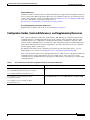
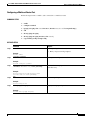
Typographic Conventions
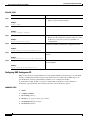
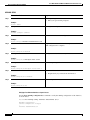
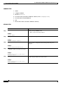
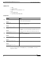
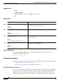
Cisco IOS documentation uses the following typographic conventions:
Convention
Description
^ or Ctrl
Both the ^ symbol and Ctrl represent the Control (Ctrl) key on a keyboard. For
example, the key combination ^D or Ctrl-D means that you hold down the
Control key while you press the D key. (Keys are indicated in capital letters but
are not case sensitive.)
string
A string is a nonquoted set of characters shown in italics. For example, when
setting a Simple Network Management Protocol (SNMP) community string to
public, do not use quotation marks around the string; otherwise, the string will
include the quotation marks.
Command Syntax Conventions
Cisco IOS documentation uses the following command syntax conventions:
ii
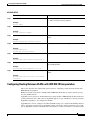
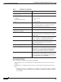
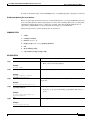
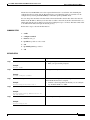
Convention
Description
bold
Bold text indicates commands and keywords that you enter as shown.
italic
Italic text indicates arguments for which you supply values.
[x]
Square brackets enclose an optional keyword or argument.
|
A vertical line, called a pipe, indicates a choice within a set of keywords
or arguments.
[x | y]
Square brackets enclosing keywords or arguments separated by a pipe indicate an
optional choice.
{x | y}
Braces enclosing keywords or arguments separated by a pipe indicate a
required choice.
[x {y | z}]
Braces and a pipe within square brackets indicate a required choice within an
optional element.
About Cisco IOS and Cisco IOS XE Software Documentation
Documentation Organization
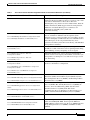
Software Conventions
Cisco IOS uses the following program code conventions:
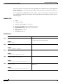
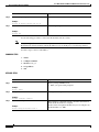
Convention
Description
Courier font
Courier font is used for information that is displayed on a PC or terminal screen.
Bold Courier font
Bold Courier font indicates text that the user must enter.
<
>
!
[
Angle brackets enclose text that is not displayed, such as a password. Angle
brackets also are used in contexts in which the italic font style is not supported;
for example, ASCII text.
An exclamation point at the beginning of a line indicates that the text that follows
is a comment, not a line of code. An exclamation point is also displayed by
Cisco IOS software for certain processes.
]
Square brackets enclose default responses to system prompts.
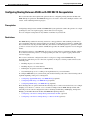
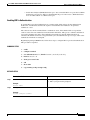
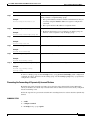
Reader Alert Conventions
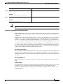
The Cisco IOS documentation set uses the following conventions for reader alerts:
Caution
Note
Timesaver
Means reader be careful. In this situation, you might do something that could result in equipment
damage or loss of data.
Means reader take note. Notes contain helpful suggestions or references to material not covered in the
manual.
Means the described action saves time. You can save time by performing the action described in the
paragraph.
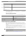
Documentation Organization
This section describes the Cisco IOS documentation set, how it is organized, and how to access it on
Cisco.com. Included are lists of configuration guides, command references, and supplementary
references and resources that make up the documentation set. The following topics are included:
•
Cisco IOS Documentation Set, page iv
•
Cisco IOS Documentation on Cisco.com, page iv
•
Configuration Guides, Command References, and Supplementary Resources, page v
iii
About Cisco IOS and Cisco IOS XE Software Documentation
Documentation Organization
Cisco IOS Documentation Set
Cisco IOS documentation consists of the following:
•
Release notes and caveats provide information about platform, technology, and feature support for
a release and describe severity 1 (catastrophic), severity 2 (severe), and severity 3 (moderate) defects
in released Cisco IOS code. Review release notes before other documents to learn whether or not
updates have been made to a feature.
•
Sets of configuration guides and command references organized by technology and published for
each standard Cisco IOS release.
– Configuration guides—Compilations of documents that provide informational and
task-oriented descriptions of Cisco IOS features.
– Command references—Compilations of command pages that provide detailed information
about the commands used in the Cisco IOS features and processes that make up the related
configuration guides. For each technology, there is a single command reference that covers all
Cisco IOS releases and that is updated at each standard release.
•
Lists of all the commands in a specific release and all commands that are new, modified, removed,
or replaced in the release.
•
Command reference book for debug commands. Command pages are listed in alphabetical order.
•
Reference book for system messages for all Cisco IOS releases.
Cisco IOS Documentation on Cisco.com
The following sections describe the documentation organization and how to access various document
types.
Use Cisco Feature Navigator to find information about platform support and Cisco IOS and Catalyst OS
software image support. To access Cisco Feature Navigator, go to http://www.cisco.com/go/cfn. An
account on Cisco.com is not required.
New Features List
The New Features List for each release provides a list of all features in the release with hyperlinks to the
feature guides in which they are documented.
Feature Guides
Cisco IOS features are documented in feature guides. Feature guides describe one feature or a group of
related features that are supported on many different software releases and platforms. Your Cisco IOS
software release or platform may not support all the features documented in a feature guide. See the
Feature Information table at the end of the feature guide for information about which features in that
guide are supported in your software release.
Configuration Guides
Configuration guides are provided by technology and release and comprise a set of individual feature
guides relevant to the release and technology.
iv
About Cisco IOS and Cisco IOS XE Software Documentation
Documentation Organization
Command References
Command reference books describe Cisco IOS commands that are supported in many different software
releases and on many different platforms. The books are provided by technology. For information about
all Cisco IOS commands, use the Command Lookup Tool at http://tools.cisco.com/Support/CLILookup
or the Cisco IOS Master Command List, All Releases, at
http://www.cisco.com/en/US/docs/ios/mcl/all_release/all_mcl.html.
Cisco IOS Supplementary Documents and Resources
Supplementary documents and resources are listed in Table 2 on page xi.
Configuration Guides, Command References, and Supplementary Resources
Table 1 lists, in alphabetical order, Cisco IOS and Cisco IOS XE software configuration guides and
command references, including brief descriptions of the contents of the documents. The Cisco IOS
command references are comprehensive, meaning that they include commands for both Cisco IOS
software and Cisco IOS XE software, for all releases. The configuration guides and command references
support many different software releases and platforms. Your Cisco IOS software release or platform
may not support all these technologies.
For additional information about configuring and operating specific networking devices, go to the
Product Support area of Cisco.com at http://www.cisco.com/web/psa/products/index.html.
Table 2 lists documents and resources that supplement the Cisco IOS software configuration guides and
command references. These supplementary resources include release notes and caveats; master
command lists; new, modified, removed, and replaced command lists; system messages; and the debug
command reference.
Table 1
Cisco IOS and Cisco IOS XE Configuration Guides and Command References
Configuration Guide and Command Reference Titles
Features/Protocols/Technologies
Cisco IOS AppleTalk Configuration Guide
AppleTalk protocol.
Cisco IOS XE AppleTalk Configuration Guide
Cisco IOS AppleTalk Command Reference
Cisco IOS Asynchronous Transfer Mode
Configuration Guide
LAN ATM, multiprotocol over ATM (MPoA), and WAN ATM.
Cisco IOS Asynchronous Transfer Mode
Command Reference
v
About Cisco IOS and Cisco IOS XE Software Documentation
Documentation Organization
Table 1
Cisco IOS and Cisco IOS XE Configuration Guides and Command References (continued)
Configuration Guide and Command Reference Titles
Cisco IOS Bridging and IBM Networking
Configuration Guide
Features/Protocols/Technologies
•
Transparent and source-route transparent (SRT) bridging,
source-route bridging (SRB), Token Ring Inter-Switch Link
(TRISL), and token ring route switch module (TRRSM).
•
Data-link switching plus (DLSw+), serial tunnel (STUN),
block serial tunnel (BSTUN); logical link control, type 2
(LLC2), synchronous data link control (SDLC); IBM
Network Media Translation, including Synchronous Data
Logical Link Control (SDLLC) and qualified LLC (QLLC);
downstream physical unit (DSPU), Systems Network
Architecture (SNA) service point, SNA frame relay access,
advanced peer-to-peer networking (APPN), native client
interface architecture (NCIA) client/server topologies, and
IBM Channel Attach.
Cisco IOS Bridging Command Reference
Cisco IOS IBM Networking Command Reference
Cisco IOS Broadband and DSL Configuration Guide
Cisco IOS XE Broadband and DSL Configuration Guide
Point-to-Point Protocol (PPP) over ATM (PPPoA) and PPP over
Ethernet (PPPoE).
Cisco IOS Broadband and DSL Command Reference
Cisco IOS Carrier Ethernet Configuration Guide
Cisco IOS Carrier Ethernet Command Reference
Cisco IOS Configuration Fundamentals
Configuration Guide
Cisco IOS XE Configuration Fundamentals
Configuration Guide
Connectivity fault management (CFM), Ethernet Local
Management Interface (ELMI), IEEE 802.3ad link bundling,
Link Layer Discovery Protocol (LLDP), media endpoint
discovery (MED), and operations, administration, and
maintenance (OAM).
Autoinstall, Setup, Cisco IOS command-line interface (CLI),
Cisco IOS file system (IFS), Cisco IOS web browser user
interface (UI), basic file transfer services, and file management.
Cisco IOS Configuration Fundamentals
Command Reference
Cisco IOS DECnet Configuration Guide
DECnet protocol.
Cisco IOS XE DECnet Configuration Guide
Cisco IOS DECnet Command Reference
Cisco IOS Dial Technologies Configuration Guide
Cisco IOS XE Dial Technologies Configuration Guide
Cisco IOS Dial Technologies Command Reference
Cisco IOS Flexible NetFlow Configuration Guide
Cisco IOS Flexible NetFlow Command Reference
vi
Asynchronous communications, dial backup, dialer technology,
dial-in terminal services and AppleTalk remote access (ARA),
large scale dialout, dial-on-demand routing, dialout, modem and
resource pooling, ISDN, multilink PPP (MLP), PPP, virtual
private dialup network (VPDN).
Flexible NetFlow.
About Cisco IOS and Cisco IOS XE Software Documentation
Documentation Organization
Table 1
Cisco IOS and Cisco IOS XE Configuration Guides and Command References (continued)
Configuration Guide and Command Reference Titles
Features/Protocols/Technologies
Cisco IOS H.323 Configuration Guide
Gatekeeper enhancements for managed voice services,
Gatekeeper Transaction Message Protocol, gateway codec order
preservation and shutdown control, H.323 dual tone
multifrequency relay, H.323 version 2 enhancements, Network
Address Translation (NAT) support of H.323 v2 Registration,
Admission, and Status (RAS) protocol, tokenless call
authorization, and VoIP gateway trunk and
carrier-based routing.
Cisco IOS High Availability Configuration Guide
A variety of High Availability (HA) features and technologies
that are available for different network segments (from
enterprise access to service provider core) to facilitate creation
of end-to-end highly available networks. Cisco IOS HA features
and technologies can be categorized in three key areas:
system-level resiliency, network-level resiliency, and embedded
management for resiliency.
Cisco IOS XE High Availability Configuration Guide
Cisco IOS High Availability Command Reference
Cisco IOS Integrated Session Border Controller
Command Reference
A VoIP-enabled device that is deployed at the edge of networks.
An SBC is a toolkit of functions, such as signaling interworking,
network hiding, security, and quality of service (QoS).
Cisco IOS Intelligent Service Gateway
Configuration Guide
Cisco IOS Intelligent Service Gateway
Command Reference
Subscriber identification, service and policy determination,
session creation, session policy enforcement, session life-cycle
management, accounting for access and service usage, session
state monitoring.
Cisco IOS Interface and Hardware Component
Configuration Guide
LAN interfaces, logical interfaces, serial interfaces, virtual
interfaces, and interface configuration.
Cisco IOS XE Interface and Hardware Component
Configuration Guide
Cisco IOS Interface and Hardware Component
Command Reference
Cisco IOS IP Addressing Services Configuration Guide
Cisco IOS XE Addressing Services Configuration Guide
Cisco IOS IP Addressing Services Command Reference
Cisco IOS IP Application Services Configuration Guide
Cisco IOS XE IP Application Services Configuration
Guide
Cisco IOS IP Application Services Command Reference
Cisco IOS IP Mobility Configuration Guide
Address Resolution Protocol (ARP), Network Address
Translation (NAT), Domain Name System (DNS), Dynamic
Host Configuration Protocol (DHCP), and Next Hop Address
Resolution Protocol (NHRP).
Enhanced Object Tracking (EOT), Gateway Load Balancing
Protocol (GLBP), Hot Standby Router Protocol (HSRP), IP
Services, Server Load Balancing (SLB), Stream Control
Transmission Protocol (SCTP), TCP, Web Cache
Communication Protocol (WCCP), User Datagram Protocol
(UDP), and Virtual Router Redundancy Protocol (VRRP).
Mobile ad hoc networks (MANet) and Cisco mobile networks.
Cisco IOS IP Mobility Command Reference
Cisco IOS IP Multicast Configuration Guide
Cisco IOS XE IP Multicast Configuration Guide
Cisco IOS IP Multicast Command Reference
Protocol Independent Multicast (PIM) sparse mode (PIM-SM),
bidirectional PIM (bidir-PIM), Source Specific Multicast
(SSM), Multicast Source Discovery Protocol (MSDP), Internet
Group Management Protocol (IGMP), and Multicast VPN
(MVPN).
vii
About Cisco IOS and Cisco IOS XE Software Documentation
Documentation Organization
Table 1
Cisco IOS and Cisco IOS XE Configuration Guides and Command References (continued)
Configuration Guide and Command Reference Titles
Features/Protocols/Technologies
Cisco IOS IP Routing Protocols Configuration Guide
Cisco IOS IP Routing Protocols Command Reference
Border Gateway Protocol (BGP), multiprotocol BGP,
multiprotocol BGP extensions for IP multicast, bidirectional
forwarding detection (BFD), Enhanced Interior Gateway
Routing Protocol (EIGRP), Interior Gateway Routing Protocol
(IGRP), Intermediate System-to-Intermediate System (IS-IS),
on-demand routing (ODR), Open Shortest Path First (OSPF),
and Routing Information Protocol (RIP).
Cisco IOS IP SLAs Configuration Guide
Cisco IOS IP Service Level Agreements (IP SLAs).
Cisco IOS XE IP Routing Protocols Configuration Guide
Cisco IOS XE IP SLAs Configuration Guide
Cisco IOS IP SLAs Command Reference
Cisco IOS IP Switching Configuration Guide
Cisco IOS XE IP Switching Configuration Guide
Cisco Express Forwarding, fast switching, and Multicast
Distributed Switching (MDS).
Cisco IOS IP Switching Command Reference
Cisco IOS IPv6 Configuration Guide
Cisco IOS XE IPv6 Configuration Guide
For IPv6 features, protocols, and technologies, go to the IPv6
“Start Here” document at the following URL:
Cisco IOS IPv6 Command Reference
http://www.cisco.com/en/US/docs/ios/ipv6/configuration/
guide/ip6-roadmap.html
Cisco IOS ISO CLNS Configuration Guide
ISO connectionless network service (CLNS).
Cisco IOS XE ISO CLNS Configuration Guide
Cisco IOS ISO CLNS Command Reference
Cisco IOS LAN Switching Configuration Guide
Cisco IOS XE LAN Switching Configuration Guide
VLANs, Inter-Switch Link (ISL) encapsulation, IEEE 802.10
encapsulation, IEEE 802.1Q encapsulation, and multilayer
switching (MLS).
Cisco IOS LAN Switching Command Reference
Cisco IOS Mobile Wireless Gateway GPRS Support Node
Configuration Guide
Cisco IOS Mobile Wireless Gateway GPRS Support Node
Command Reference
Cisco IOS Mobile Wireless Home Agent
Configuration Guide
Cisco IOS Mobile Wireless Home Agent
Command Reference
Cisco IOS Mobile Wireless Packet Data Serving Node
Configuration Guide
Cisco IOS Mobile Wireless Packet Data Serving Node
Command Reference
Cisco IOS Mobile Wireless Radio Access Networking
Configuration Guide
Cisco IOS Mobile Wireless Radio Access Networking
Command Reference
viii
Cisco IOS Gateway GPRS Support Node (GGSN) in a
2.5-generation general packet radio service (GPRS) and
3-generation universal mobile telecommunication system (UMTS)
network.
Cisco Mobile Wireless Home Agent, an anchor point for mobile
terminals for which mobile IP or proxy mobile IP services are
provided.
Cisco Packet Data Serving Node (PDSN), a wireless gateway that
is between the mobile infrastructure and standard IP networks and
that enables packet data services in a code division multiple access
(CDMA) environment.
Cisco IOS radio access network products.
About Cisco IOS and Cisco IOS XE Software Documentation
Documentation Organization
Table 1
Cisco IOS and Cisco IOS XE Configuration Guides and Command References (continued)
Configuration Guide and Command Reference Titles
Features/Protocols/Technologies
Cisco IOS Multiprotocol Label Switching
Configuration Guide
MPLS Label Distribution Protocol (LDP), MPLS Layer 2 VPNs,
MPLS Layer 3 VPNs, MPLS Traffic Engineering (TE), and
MPLS Embedded Management (EM) and MIBs.
Cisco IOS XE Multiprotocol Label Switching
Configuration Guide
Cisco IOS Multiprotocol Label Switching
Command Reference
Cisco IOS Multi-Topology Routing Configuration Guide
Cisco IOS Multi-Topology Routing Command Reference
Cisco IOS NetFlow Configuration Guide
Cisco IOS XE NetFlow Configuration Guide
Unicast and multicast topology configurations, traffic
classification, routing protocol support, and network
management support.
Network traffic data analysis, aggregation caches, export
features.
Cisco IOS NetFlow Command Reference
Cisco IOS Network Management Configuration Guide
Basic system management; system monitoring and logging;
troubleshooting, logging, and fault management;
Cisco IOS XE Network Management Configuration Guide
Cisco Discovery Protocol; Cisco IOS Scripting with Tool
Cisco IOS Network Management Command Reference
Control Language (Tcl); Cisco networking services (CNS);
DistributedDirector; Embedded Event Manager (EEM);
Embedded Resource Manager (ERM); Embedded Syslog
Manager (ESM); HTTP; Remote Monitoring (RMON); SNMP;
and VPN Device Manager Client for Cisco IOS Software
(XSM Configuration).
Cisco IOS Novell IPX Configuration Guide
Novell Internetwork Packet Exchange (IPX) protocol.
Cisco IOS XE Novell IPX Configuration Guide
Cisco IOS Novell IPX Command Reference
Cisco IOS Optimized Edge Routing Configuration Guide
Cisco IOS Optimized Edge Routing Command Reference
Cisco IOS Quality of Service Solutions
Configuration Guide
Cisco IOS XE Quality of Service Solutions
Configuration Guide
Cisco IOS Quality of Service Solutions
Command Reference
Cisco IOS Security Configuration Guide
Cisco IOS XE Security Configuration Guide
Cisco IOS Security Command Reference
Optimized edge routing (OER) monitoring, policy
configuration, routing control, logging and reporting, and
VPN IPsec/generic routing encapsulation (GRE) tunnel
interface optimization.
Class-based weighted fair queuing (CBWFQ), custom queuing,
distributed traffic shaping (DTS), generic traffic shaping (GTS),
IP- to-ATM class of service (CoS), low latency queuing (LLQ),
modular QoS CLI (MQC), Network-Based Application
Recognition (NBAR), priority queuing, Security Device
Manager (SDM), Multilink PPP (MLPPP) for QoS, header
compression, AutoQoS, QoS features for voice, Resource
Reservation Protocol (RSVP), weighted fair queuing (WFQ),
and weighted random early detection (WRED).
Access control lists (ACLs), authentication, authorization, and
accounting (AAA), firewalls, IP security and encryption,
neighbor router authentication, network access security, network
data encryption with router authentication, public key
infrastructure (PKI), RADIUS, TACACS+, terminal access
security, and traffic filters.
ix
About Cisco IOS and Cisco IOS XE Software Documentation
Documentation Organization
Table 1
Cisco IOS and Cisco IOS XE Configuration Guides and Command References (continued)
Configuration Guide and Command Reference Titles
Features/Protocols/Technologies
Cisco IOS Service Selection Gateway Configuration Guide Subscriber authentication, service access, and accounting.
Cisco IOS Service Selection Gateway Command Reference
Cisco IOS Software Activation Configuration Guide
Cisco IOS Software Activation Command Reference
Cisco IOS Software Modularity Installation and
Configuration Guide
Cisco IOS Software Modularity Command Reference
Cisco IOS Terminal Services Configuration Guide
Cisco IOS Terminal Services Command Reference
An orchestrated collection of processes and components to
activate Cisco IOS software feature sets by obtaining and
validating Cisco software licenses.
Installation and basic configuration of software modularity
images, including installations on single and dual route
processors, installation rollbacks, software modularity binding,
software modularity processes and patches.
DEC, local-area transport (LAT), and X.25 packet
assembler/disassembler (PAD).
Cisco IOS XE Terminal Services Command Reference
Cisco IOS Virtual Switch Command Reference
Virtual switch redundancy, high availability, and packet handling;
converting between standalone and virtual switch modes; virtual
switch link (VSL); Virtual Switch Link Protocol (VSLP).
Note
Cisco IOS Voice Configuration Library
Cisco IOS Voice Command Reference
Cisco IOS VPDN Configuration Guide
Cisco IOS XE VPDN Configuration Guide
Cisco IOS VPDN Command Reference
For information about virtual switch configuration, refer
to the product-specific software configuration
information for the Cisco Catalyst 6500 series switch or
for the Metro Ethernet 6500 series switch.
Cisco IOS support for voice call control protocols, interoperability,
physical and virtual interface management, and troubleshooting.
The library includes documentation for IP telephony applications.
Layer 2 Tunneling Protocol (L2TP) dial-out load balancing and
redundancy, L2TP extended failover, L2TP security VPDN,
multihop by Dialed Number Identification Service (DNIS),
timer and retry enhancements for L2TP and Layer 2 Forwarding
(L2F), RADIUS Attribute 82: tunnel assignment ID, shell-based
authentication of VPDN users, tunnel authentication via
RADIUS on tunnel terminator.
Cisco IOS Wide-Area Networking Configuration Guide
Frame Relay, Layer 2 Tunneling Protocol Version 3 (L2TPv3),
Link Access Procedure, Balanced (LAPB), Switched
Cisco IOS XE Wide-Area Networking Configuration Guide
Multimegabit Data Service (SMDS), and X.25.
Cisco IOS Wide-Area Networking Command Reference
Cisco IOS Wireless LAN Configuration Guide
Cisco IOS Wireless LAN Command Reference
x
Broadcast key rotation, IEEE 802.11x support, IEEE 802.1x
authenticator, IEEE 802.1x local authentication service for
Extensible Authentication Protocol-Flexible Authentication via
Secure Tunneling (EAP-FAST), Multiple Basic Service Set ID
(BSSID), Wi-Fi Multimedia (WMM) required elements, and
Wi-Fi Protected Access (WPA).
About Cisco IOS and Cisco IOS XE Software Documentation
Additional Resources and Documentation Feedback
Table 2
Cisco IOS Supplementary Documents and Resources
Document Title
Description
Cisco IOS Master Command List, All Releases
Alphabetical list of all the commands documented in all
Cisco IOS releases.
Cisco IOS New, Modified, Removed, and
Replaced Commands
List of all the new, modified, removed, and replaced commands
for a Cisco IOS release.
Cisco IOS Software System Messages
List of Cisco IOS system messages and descriptions. System
messages may indicate problems with your system; be
informational only; or may help diagnose problems with
communications lines, internal hardware, or the
system software.
Cisco IOS Debug Command Reference
Alphabetical list of debug commands including brief
descriptions of use, command syntax, and usage guidelines.
Release Notes and Caveats
Information about new and changed features, system
requirements, and other useful information about specific
software releases; information about defects in specific
Cisco IOS software releases.
MIBs
Files used for network monitoring. To locate and download
MIBs for selected platforms, Cisco IOS releases, and feature
sets, use Cisco MIB Locator at the following URL:
http://www.cisco.com/go/mibs
RFCs
Standards documents maintained by the Internet Engineering
Task Force (IETF) that Cisco IOS documentation references
where applicable. The full text of referenced RFCs may be
obtained at the following URL:
http://www.rfc-editor.org/
Additional Resources and Documentation Feedback
What’s New in Cisco Product Documentation is published monthly and describes all new and revised
Cisco technical documentation. The What’s New in Cisco Product Documentation publication also
provides information about obtaining the following resources:
•
Technical documentation
•
Cisco product security overview
•
Product alerts and field notices
•
Technical assistance
Cisco IOS technical documentation includes embedded feedback forms where you can rate documents
and provide suggestions for improvement. Your feedback helps us improve our documentation.
xi
About Cisco IOS and Cisco IOS XE Software Documentation
Additional Resources and Documentation Feedback
CCDE, CCENT, Cisco Eos, Cisco Lumin, Cisco Nexus, Cisco StadiumVision, Cisco TelePresence, the Cisco logo, DCE, and Welcome to the
Human Network are trademarks; Changing the Way We Work, Live, Play, and Learn and Cisco Store are service marks; and Access Registrar,
Aironet, AsyncOS, Bringing the Meeting To You, Catalyst, CCDA, CCDP, CCIE, CCIP, CCNA, CCNP, CCSP, CCVP, Cisco, the Cisco Certified
Internetwork Expert logo, Cisco IOS, Cisco Press, Cisco Systems, Cisco Systems Capital, the Cisco Systems logo, Cisco Unity, Collaboration
Without Limitation, EtherFast, EtherSwitch, Event Center, Fast Step, Follow Me Browsing, FormShare, GigaDrive, HomeLink, Internet Quotient,
IOS, iPhone, iQ Expertise, the iQ logo, iQ Net Readiness Scorecard, iQuick Study, IronPort, the IronPort logo, LightStream, Linksys, MediaTone,
MeetingPlace, MeetingPlace Chime Sound, MGX, Networkers, Networking Academy, Network Registrar, PCNow, PIX, PowerPanels, ProConnect,
ScriptShare, SenderBase, SMARTnet, Spectrum Expert, StackWise, The Fastest Way to Increase Your Internet Quotient, TransPath, WebEx, and
the WebEx logo are registered trademarks of Cisco Systems, Inc. and/or its affiliates in the United States and certain other countries.
All other trademarks mentioned in this document or Website are the property of their respective owners. The use of the word partner does not imply
a partnership relationship between Cisco and any other company. (0807R)
Any Internet Protocol (IP) addresses used in this document are not intended to be actual addresses. Any examples, command display output, and
figures included in the document are shown for illustrative purposes only. Any use of actual IP addresses in illustrative content is unintentional and
coincidental.
© 2007–2008 Cisco Systems, Inc. All rights reserved.
xii
Using the Command-Line Interface in Cisco IOS
and Cisco IOS XE Software
Last updated: August 6, 2008
This document provides basic information about the command-line interface (CLI) in Cisco IOS and
Cisco IOS XE software and how you can use some of the CLI features. This document contains the
following sections:
•
Initially Configuring a Device, page i
•
Using the CLI, page ii
•
Saving Changes to a Configuration, page xii
•
Additional Information, page xii
For more information about using the CLI, see the “Using the Cisco IOS Command-Line Interface”
section of the Cisco IOS Configuration Fundamentals Configuration Guide.
For information about the software documentation set, see the “About Cisco IOS and Cisco IOS XE
Software Documentation” document.
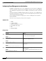
Initially Configuring a Device
Initially configuring a device varies by platform. For information about performing an initial
configuration, see the hardware installation documentation that is provided with the original packaging
of the product or go to the Product Support area of Cisco.com at
http://www.cisco.com/web/psa/products/index.html.
After you have performed the initial configuration and connected the device to your network, you can
configure the device by using the console port or a remote access method, such as Telnet or Secure Shell
(SSH), to access the CLI or by using the configuration method provided on the device, such as Security
Device Manager.
i
Using the Command-Line Interface in Cisco IOS and Cisco IOS XE Software
Using the CLI
Changing the Default Settings for a Console or AUX Port
There are only two changes that you can make to a console port and an AUX port:
Note
•
Change the port speed with the config-register 0x command. Changing the port speed is not
recommended. The well-known default speed is 9600.
•
Change the behavior of the port; for example, by adding a password or changing the timeout value.
The AUX port on the Route Processor (RP) installed in a Cisco ASR1000 series router does not serve
any useful customer purpose and should be accessed only under the advisement of a customer support
representative.
Using the CLI
This section describes the following topics:
•
Understanding Command Modes, page ii
•
Using the Interactive Help Feature, page v
•
Understanding Command Syntax, page vi
•
Understanding Enable and Enable Secret Passwords, page viii
•
Using the Command History Feature, page viii
•
Abbreviating Commands, page ix
•
Using Aliases for CLI Commands, page ix
•
Using the no and default Forms of Commands, page x
•
Using the debug Command, page x
•
Filtering Output Using Output Modifiers, page x
•
Understanding CLI Error Messages, page xi
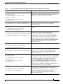
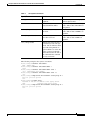
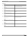
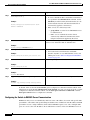
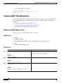
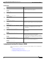
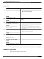
Understanding Command Modes
The CLI command mode structure is hierarchical, and each mode supports a set of specific commands.
This section describes the most common of the many modes that exist.
Table 1 lists common command modes with associated CLI prompts, access and exit methods, and a
brief description of how each mode is used.
ii
Using the Command-Line Interface in Cisco IOS and Cisco IOS XE Software
Using the CLI
Table 1
CLI Command Modes
Command
Mode
Access Method
Prompt
Exit Method
User EXEC
Log in.
Router>
Issue the logout or exit
command.
Privileged
EXEC
From user EXEC mode,
issue the enable
command.
Router#
Issue the disable
command or the exit
command to return to
user EXEC mode.
Mode Usage
•
Change terminal
settings.
•
Perform basic tests.
•
Display device status.
•
Issue show and debug
commands.
•
Copy images to the
device.
•
Reload the device.
•
Manage device
configuration files.
•
Manage device file
systems.
Global
configuration
From privileged EXEC
mode, issue the
configure terminal
command.
Router(config)#
Issue the exit command Configure the device.
or the end command to
return to privileged
EXEC mode.
Interface
configuration
From global
configuration mode,
issue the interface
command.
Router(config-if)#
Issue the exit command Configure individual
to return to global
interfaces.
configuration mode or
the end command to
return to privileged
EXEC mode.
Line
configuration
Router(config-line)# Issue the exit command Configure individual
From global
to return to global
terminal lines.
configuration mode,
configuration mode or
issue the line vty or line
the end command to
console command.
return to privileged
EXEC mode.
iii
Using the Command-Line Interface in Cisco IOS and Cisco IOS XE Software
Using the CLI
Table 1
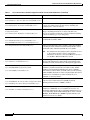
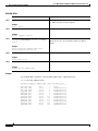
CLI Command Modes (continued)
Command
Mode
Access Method
Prompt
Exit Method
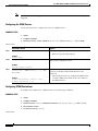
ROM monitor
From privileged EXEC
mode, issue the reload
command. Press the
Break key during the
first 60 seconds while
the system is booting.
rommon # >
Issue the continue
command.
Diagnostic
(available only
on the Cisco
ASR1000
series router)
Router(diag)#
The router boots or
enters diagnostic mode
in the following
scenarios. When a
Cisco IOS process or
processes fail, in most
scenarios the router will
reload.
•
•
•
iv
The # symbol
represents the line
number and increments
at each prompt.
A user-configured
access policy was
configured using
the transport-map
command, which
directed the user
into diagnostic
mode.
The router was
accessed using an
RP auxiliary port.
A break signal
(Ctrl-C,
Ctrl-Shift-6, or the
send break
command) was
entered, and the
router was
configured to enter
diagnostic mode
when the break
signal was received.
If a Cisco IOS process
failure is the reason for
entering diagnostic
mode, the failure must
be resolved and the
router must be rebooted
to exit diagnostic mode.
If the router is in
diagnostic mode
because of a
transport-map
configuration, access
the router through
another port or using a
method that is
configured to connect to
the Cisco IOS CLI.
If the RP auxiliary port
was used to access the
router, use another port
for access. Accessing
the router through the
auxiliary port is not
useful for customer
purposes.
Mode Usage
•
Run as the default
operating mode when a
valid image cannot be
loaded.
•
Access the fall-back
procedure for loading an
image when the device
lacks a valid image and
cannot be booted.
•
Perform password
recovery when a
CTRL-Break sequence is
issued within 60 seconds
of a power-on or reload
event.
•
Inspect various states on
the router, including the
Cisco IOS state.
•
Replace or roll back the
configuration.
•
Provide methods of
restarting the Cisco IOS
software or other
processes.
•
Reboot hardware, such
as the entire router, an
RP, an ESP, a SIP, a SPA,
or possibly other
hardware components.
•
Transfer files into or off
of the router using
remote access methods
such as FTP, TFTP, and
SCP.
Using the Command-Line Interface in Cisco IOS and Cisco IOS XE Software
Using the CLI
EXEC commands are not saved when the software reboots. Commands that you issue in a configuration
mode can be saved to the startup configuration. If you save the running configuration to the startup
configuration, these commands will execute when the software is rebooted. Global configuration mode
is the highest level of configuration mode. From global configuration mode, you can enter a variety of
other configuration modes, including protocol-specific modes.
ROM monitor mode is a separate mode that is used when the software cannot load properly. If a valid
software image is not found when the software boots or if the configuration file is corrupted at startup,
the software might enter ROM monitor mode. Use the question symbol (?) to view the commands that
you can use while the device is in ROM monitor mode.
rommon 1 > ?
alias
boot
confreg
cont
context
cookie
.
.
.
rommon 2 >
set and display aliases command
boot up an external process
configuration register utility
continue executing a downloaded image
display the context of a loaded image
display contents of cookie PROM in hex
The following example shows how the command prompt changes to indicate a different command mode:
Router> enable
Router# configure terminal
Router(config)# interface ethernet 1/1
Router(config-if)# ethernet
Router(config-line)# exit
Router(config)# end
Router#
Note
A keyboard alternative to the end command is Ctrl-Z.
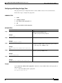
Using the Interactive Help Feature
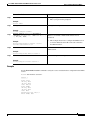
The CLI includes an interactive Help feature. Table 2 describes how to use the Help feature.
Table 2
CLI Interactive Help Commands
Command
Purpose
help
Provides a brief description of the help feature in any command mode.
?
Lists all commands available for a particular command mode.
partial command?
Provides a list of commands that begin with the character string (no
space between the command and the question mark).
partial command<Tab>
Completes a partial command name (no space between the command
and <Tab>).
command ?
Lists the keywords, arguments, or both associated with the command
(space between the command and the question mark).
command keyword ?
Lists the arguments that are associated with the keyword (space between
the keyword and the question mark).
v
Using the Command-Line Interface in Cisco IOS and Cisco IOS XE Software
Using the CLI
The following examples show how to use the help commands:
help
Router> help
Help may be requested at any point in a command by entering a question mark '?'. If
nothing matches, the help list will be empty and you must backup until entering a '?'
shows the available options.
Two styles of help are provided:
1. Full help is available when you are ready to enter a command argument (e.g. 'show ?')
and describes each possible argument.
2. Partial help is provided when an abbreviated argument is entered and you want to know
what arguments match the input (e.g. 'show pr?'.)
?
Router# ?
Exec commands:
access-enable
access-profile
access-template
alps
archive
<snip>
Create a temporary access-List entry
Apply user-profile to interface
Create a temporary access-List entry
ALPS exec commands
manage archive files
partial command?
Router(config)# zo?
zone zone-pair
partial command<Tab>
Router(config)# we<Tab> webvpn
command ?
Router(config-if)# pppoe ?
enable
Enable pppoe
max-sessions Maximum PPPOE sessions
command keyword ?
Router(config-if)# pppoe enable ?
group attach a BBA group
<cr>
Understanding Command Syntax
Command syntax is the format in which a command should be entered in the CLI. Commands include
the name of the command, keywords, and arguments. Keywords are alphanumeric strings that are used
literally. Arguments are placeholders for values that a user must supply. Keywords and arguments may
be required or optional.
Specific conventions convey information about syntax and command elements. Table 3 describes these
conventions.
vi
Using the Command-Line Interface in Cisco IOS and Cisco IOS XE Software
Using the CLI
Table 3
CLI Syntax Conventions
Symbol/Text
Function
Notes
< > (angle brackets)
Indicate that the option is an
argument.
Sometimes arguments are displayed
without angle brackets.
A.B.C.D.
Indicates that you must enter a
dotted decimal IP address.
Angle brackets (< >) are not always
used to indicate that an IP address is
an argument.
WORD (all capital letters)
Indicates that you must enter
one word.
Angle brackets (< >) are not always
used to indicate that a WORD is an
argument.
LINE (all capital letters)
Indicates that you must enter
more than one word.
Angle brackets (< >) are not always
used to indicate that a LINE is an
argument.
<cr> (carriage return)
Indicates the end of the list of —
available keywords and arguments, and also indicates when
keywords and arguments are
optional. When <cr> is the only
option, you have reached the
end of the branch or the end of
the command if the command
has only one branch.
The following examples show syntax conventions:
Router(config)# ethernet cfm domain ?
WORD domain name
Router(config)# ethernet cfm domain dname ?
level
Router(config)# ethernet cfm domain dname level ?
<0-7> maintenance level number
Router(config)# ethernet cfm domain dname level 7 ?
<cr>
Router(config)# snmp-server file-transfer access-group 10 ?
protocol protocol options
<cr>
Router(config)# logging host ?
Hostname or A.B.C.D IP address of the syslog server
ipv6
Configure IPv6 syslog server
Router(config)# snmp-server file-transfer access-group 10 ?
protocol protocol options
<cr>
vii
Using the Command-Line Interface in Cisco IOS and Cisco IOS XE Software
Using the CLI
Understanding Enable and Enable Secret Passwords
Some privileged EXEC commands are used for actions that impact the system, and it is recommended
that you set a password for these commands to prevent unauthorized use. Two types of passwords, enable
(not encrypted) and enable secret (encrypted), can be set. The following commands set these passwords
and are issued in global configuration mode:
•
enable password
•
enable secret password
Using an enable secret password is recommended because it is encrypted and more secure than the
enable password. When you use an enable secret password, text is encrypted (unreadable) before it is
written to the config.text file. When you use an enable password, the text is written as entered (readable)
to the config.text file.
Each type of password is case sensitive, can contain from 1 to 25 uppercase and lowercase alphanumeric
characters, and can start with a number. Spaces are also valid password characters; for example,
“two words” is a valid password. Leading spaces are ignored, but trailing spaces are recognized.
Note
Both password commands have numeric keywords that are single integer values. If you choose a number
for the first character of your password followed by a space, the system will read the number as if it were
the numeric keyword and not as part of your password.
When both passwords are set, the enable secret password takes precedence over the enable password.
To remove a password, use the no form of the commands: no enable password or
no enable secret password.
For more information about password recovery procedures for Cisco products, see
http://www.cisco.com/en/US/products/sw/iosswrel/ps1831/
products_tech_note09186a00801746e6.shtml.
Using the Command History Feature
The CLI command history feature saves the commands you enter during a session in a command history
buffer. The default number of commands saved is 10, but the number is configurable within the range of
0 to 256. This command history feature is particularly useful for recalling long or complex commands.
To change the number of commands saved in the history buffer for a terminal session, issue the
terminal history size command:
Router# terminal history size num
A command history buffer is also available in line configuration mode with the same default and
configuration options. To set the command history buffer size for a terminal session in line configuration
mode, issue the history command:
Router(config-line)# history [size num]
To recall commands from the history buffer, use the following methods:
•
viii
Press Ctrl-P or the up arrow key—Recalls commands beginning with the most recent command.
Repeat the key sequence to recall successively older commands.
Using the Command-Line Interface in Cisco IOS and Cisco IOS XE Software
Using the CLI
•
Press Ctrl-N or the down arrow key—Recalls the most recent commands in the history buffer after
they have been recalled using Ctrl-P or the up arrow key. Repeat the key sequence to recall
successively more recent commands.
Note
•
The arrow keys function only on ANSI-compatible terminals such as the VT100.
Issue the show history command in user EXEC or privileged EXEC mode—Lists the most recent
commands that you entered. The number of commands that are displayed is determined by the
setting of the terminal history size and history commands.
The CLI command history feature is enabled by default. To disable this feature for a terminal
session, issue the terminal no history command in user EXEC or privileged EXEC mode or the
no history command in line configuration mode.
Abbreviating Commands
Typing a complete command name is not always required for the command to execute. The CLI
recognizes an abbreviated command when the abbreviation contains enough characters to uniquely
identify the command. For example, the show version command can be abbreviated as sh ver. It cannot
be abbreviated as s ver because s could mean show, set, or systat. The sh v abbreviation also is not valid
because the show command has vrrp as a keyword in addition to version. (Command and keyword
examples from Cisco IOS Release 12.4(13)T.)
Using Aliases for CLI Commands
To save time and the repetition of entering the same command multiple times, you can use a command
alias. An alias can be configured to do anything that can be done at the command line, but an alias cannot
move between modes, type in passwords, or perform any interactive functions.
Table 4 shows the default command aliases.
Table 4
Default Command Aliases
Command Alias
Original Command
h
help
lo
logout
p
ping
s
show
u or un
undebug
w
where
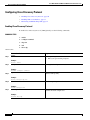
To create a command alias, issue the alias command in global configuration mode. The syntax of the
command is alias mode command-alias original-command. Following are some examples:
•
Router(config)# alias exec prt partition—privileged EXEC mode
•
Router(config)# alias configure sb source-bridge—global configuration mode
•
Router(config)# alias interface rl rate-limit—interface configuration mode
ix
Using the Command-Line Interface in Cisco IOS and Cisco IOS XE Software
Using the CLI
To view both default and user-created aliases, issue the show alias command.
For more information about the alias command, see
http://www.cisco.com/en/US/docs/ios/fundamentals/command/reference/cf_book.html.
Using the no and default Forms of Commands
Most configuration commands have a no form that is used to reset a command to its default value or
disable a feature or function. For example, the ip routing command is enabled by default. To disable this
command, you would issue the no ip routing command. To re-enable IP routing, you would issue the
ip routing command.
Configuration commands may also have a default form, which returns the command settings to their
default values. For commands that are disabled by default, using the default form has the same effect as
using the no form of the command. For commands that are enabled by default and have default settings,
the default form enables the command and returns the settings to their default values.
The no and default forms of commands are described in the command pages of command references.
Using the debug Command
A debug command produces extensive output that helps you troubleshoot problems in your network.
These commands are available for many features and functions within Cisco IOS and Cisco IOS XE
software. Some debug commands are debug all, debug aaa accounting, and debug mpls packets. To
use debug commands during a Telnet session with a device, you must first enter the terminal monitor
command. To turn off debugging completely, you must enter the undebug all command.
For more information about debug commands, see the Cisco IOS Debug Command Reference at
http://www.cisco.com/en/US/docs/ios/debug/command/reference/db_book.html.
Caution
Debugging is a high priority and high CPU utilization process that can render your device unusable. Use
debug commands only to troubleshoot specific problems. The best times to run debugging are during
periods of low network traffic and when few users are interacting with the network. Debugging during
these periods decreases the likelihood that the debug command processing overhead will affect network
performance or user access or response times.
Filtering Output Using Output Modifiers
Many commands produce lengthy output that may use several screens to display. Using output modifiers,
you can filter this output to show only the information that you want to see.
Three output modifiers are available and are described as follows:
x
•
begin regular expression—Displays the first line in which a match of the regular expression is found
and all lines that follow.
•
include regular expression—Displays all lines in which a match of the regular expression is found.
•
exclude regular expression—Displays all lines except those in which a match of the regular
expression is found.
Using the Command-Line Interface in Cisco IOS and Cisco IOS XE Software
Using the CLI
To use one of these output modifiers, type the command followed by the pipe symbol (|), the modifier,
and the regular expression that you want to search for or filter. A regular expression is a case-sensitive
alphanumeric pattern. It can be a single character or number, a phrase, or a more complex string.
The following example illustrates how to filter output of the show interface command to display only
lines that include the expression “protocol.”
Router# show interface | include protocol
FastEthernet0/0 is up, line protocol is up
Serial4/0 is up, line protocol is up
Serial4/1 is up, line protocol is up
Serial4/2 is administratively down, line protocol is down
Serial4/3 is administratively down, line protocol is down
Understanding CLI Error Messages
You may encounter some error messages while using the CLI. Table 5 shows the common CLI error
messages.
Table 5
Common CLI Error Messages
Error Message
Meaning
% Ambiguous command:
“show con”
You did not enter enough
Reenter the command followed by a
characters for the command to space and a question mark (?). The
be recognized.
keywords that you are allowed to
enter for the command appear.
% Incomplete command.
You did not enter all the
keywords or values required
by the command.
% Invalid input detected at “^” You entered the command inmarker.
correctly. The caret (^) marks
the point of the error.
How to Get Help
Reenter the command followed by a
space and a question mark (?). The
keywords that you are allowed to
enter for the command appear.
Enter a question mark (?) to display
all the commands that are available in
this command mode. The keywords
that you are allowed to enter for the
command appear.
For more system error messages, see the following documents:
•
Cisco IOS Release 12.2SR System Message Guide
•
Cisco IOS System Messages, Volume 1 of 2 (Cisco IOS Release 12.4)
•
Cisco IOS System Messages, Volume 2 of 2 (Cisco IOS Release 12.4)
xi
Using the Command-Line Interface in Cisco IOS and Cisco IOS XE Software
Saving Changes to a Configuration
Saving Changes to a Configuration
To save changes that you made to the configuration of a device, you must issue the copy running-config
startup-config command or the copy system:running-config nvram:startup-config command. When
you issue these commands, the configuration changes that you made are saved to the startup
configuration and saved when the software reloads or power to the device is turned off or interrupted.
The following example shows the syntax of the copy running-config startup-config command:
Router# copy running-config startup-config
Destination filename [startup-config]?
You press Enter to accept the startup-config filename (the default), or type a new filename and then press
Enter to accept that name. The following output is displayed indicating that the configuration was saved:
Building configuration...
[OK]
Router#
On most platforms, the configuration is saved to NVRAM. On platforms with a Class A flash file system,
the configuration is saved to the location specified by the CONFIG_FILE environment variable. The
CONFIG_FILE variable defaults to NVRAM.
Additional Information
•
“Using the Cisco IOS Command-Line Interface” section of the
Cisco IOS Configuration Fundamentals Configuration Guide:
http://www.cisco.com/en/US/docs/ios/fundamentals/configuration/guide/cf_cli-basics.html
or
“Using Cisco IOS XE Software” chapter of the Cisco ASR1000 Series Aggregation Services Routers
Software Configuration Guide:
http://www.cisco.com/en/US/docs/routers/asr1000/configuration/guide/chassis/using_cli.html
•
Cisco Product Support Resources
http://www.cisco.com/web/psa/products/index.html
•
Support area on Cisco.com (also search for documentation by task or product)
http://www.cisco.com/en/US/support/index.html
•
White Paper: Cisco IOS Reference Guide
http://www.cisco.com/en/US/products/sw/iosswrel/ps1828/products_white_paper09186a00801830
5e.shtml
•
Software Download Center (downloads; tools; licensing, registration, advisory, and general
information) (requires Cisco.com User ID and password)
http://www.cisco.com/kobayashi/sw-center/
•
Error Message Decoder, a tool to help you research and resolve error messages for
Cisco IOS software
http://www.cisco.com/pcgi-bin/Support/Errordecoder/index.cgi
xii
Using the Command-Line Interface in Cisco IOS and Cisco IOS XE Software
Additional Information
•
Command Lookup Tool, a tool to help you find detailed descriptions of Cisco IOS commands
(requires Cisco.com user ID and password)
http://tools.cisco.com/Support/CLILookup
•
Output Interpreter, a troubleshooting tool that analyzes command output of supported
show commands
https://www.cisco.com/pcgi-bin/Support/OutputInterpreter/home.pl\
CCDE, CCENT, Cisco Eos, Cisco Lumin, Cisco Nexus, Cisco StadiumVision, Cisco TelePresence, the Cisco logo, DCE, and Welcome to the
Human Network are trademarks; Changing the Way We Work, Live, Play, and Learn and Cisco Store are service marks; and Access Registrar,
Aironet, AsyncOS, Bringing the Meeting To You, Catalyst, CCDA, CCDP, CCIE, CCIP, CCNA, CCNP, CCSP, CCVP, Cisco, the Cisco Certified
Internetwork Expert logo, Cisco IOS, Cisco Press, Cisco Systems, Cisco Systems Capital, the Cisco Systems logo, Cisco Unity, Collaboration
Without Limitation, EtherFast, EtherSwitch, Event Center, Fast Step, Follow Me Browsing, FormShare, GigaDrive, HomeLink, Internet Quotient,
IOS, iPhone, iQ Expertise, the iQ logo, iQ Net Readiness Scorecard, iQuick Study, IronPort, the IronPort logo, LightStream, Linksys, MediaTone,
MeetingPlace, MeetingPlace Chime Sound, MGX, Networkers, Networking Academy, Network Registrar, PCNow, PIX, PowerPanels, ProConnect,
ScriptShare, SenderBase, SMARTnet, Spectrum Expert, StackWise, The Fastest Way to Increase Your Internet Quotient, TransPath, WebEx, and
the WebEx logo are registered trademarks of Cisco Systems, Inc. and/or its affiliates in the United States and certain other countries.
All other trademarks mentioned in this document or Website are the property of their respective owners. The use of the word partner does not imply
a partnership relationship between Cisco and any other company. (0807R)
Any Internet Protocol (IP) addresses used in this document are not intended to be actual addresses. Any examples, command display output, and
figures included in the document are shown for illustrative purposes only. Any use of actual IP addresses in illustrative content is unintentional and
coincidental.
© 2007–2008 Cisco Systems, Inc. All rights reserved.
xiii
Using the Command-Line Interface in Cisco IOS and Cisco IOS XE Software
Additional Information
xiv
Virtual LANs
Virtual LANS Features Roadmap
This roadmap lists the features documented in the Virtual LANs modules in which they appear.
Roadmap History
This roadmap was first published April 20, 2006 and last updated on April 20, 2006.
Features and Release Support
Table 1 lists Virtual LANs feature support for the following Cisco IOS software release trains:
•
Cisco IOS Releases 12.0, 12.1, 12.2, 12.3, and 12.3T
Only features that were introduced or modified in Cisco IOS Release 12.0 (1) or a later release appear
in the table. Not all features may be supported in your Cisco IOS software release.
Use Cisco Feature Navigator to find information about platform support and Cisco IOS and Catalyst OS
software image support. To access Cisco Feature Navigator, go to http://www.cisco.com/go/cfn. An
account on Cisco.com is not required.
Note
Table 1 lists only the Cisco IOS software release that introduced support for a given feature in a given
Cisco IOS software release train. Unless noted otherwise, subsequent releases of that Cisco IOS
software release train also support that feature.
Americas Headquarters:
Cisco Systems, Inc., 170 West Tasman Drive, San Jose, CA 95134-1706 USA
© 2007 Cisco Systems, Inc. All rights reserved.
Virtual LANS Features Roadmap
Table 1
Release
Supported Network Address Translation Features
Feature Name
Feature Description
Where Documented
Cisco IOS Releases 12.0, 12.1, 12.2, 12.3, and 12.3T
12.0(7)XE
VLAN Range
12.1(5)T
12.2(2)DD
12.2(4)B
12.2(8)T
Using the VLAN Range feature, you can group
VLAN subinterfaces together so that any command
entered in a group applies to every subinterface
within the group. This capability simplifies
configurations and reduces command parsing.
Configuring
Routing Between VLANs
•
Configuring a Range
of VLAN
Subinterfaces,
page 323
12.2(13)T
2
Configuring Routing
Between VLANs with
IEEE 802.1Q
Encapsulation
Configuring
The IEEE 802.1Q protocol is used to interconnect
Routing Between VLANs
multiple switches and routers, and for defining
VLAN topologies. The IEEE 802.1Q standard is
• Configuring Routing
extremely restrictive to untagged frames. The
Between VLANs with
standard provides only a per-port VLANs solution
IEEE 802.1Q
for untagged frames. For example, assigning
Encapsulation
untagged frames to VLANs takes into consideration
only the port from which they have been received.
Each port has a parameter called a permanent virtual
identification (Native VLAN) that specifies the
VLAN assigned to receive untagged frames.
Configuring Routing
Between VLANs with
Inter-Switch Link
Encapsulation
ISL is a Cisco protocol for interconnecting multiple Configuring
Routing Between VLANs
switches and maintaining VLAN information as
traffic goes between switches. ISL provides VLAN
• Configuring Routing
capabilities while maintaining full wire speed
Between
performance on Fast Ethernet links in full- or
VLANs with
half-duplex mode. ISL operates in a point-to-point
Inter-Switch Link
environment and will support up to 1000 VLANs.
Encapsulation
You can define virtually as many logical networks as
are necessary for your environment.
Configuring Routing
Between VLANs with
IEEE 802.10
Encapsulation
AppleTalk can be routed over VLAN subinterfaces Configuring
Routing Between VLANs
using the ISL or IEEE 802.10 VLANs feature that
provides full-feature Cisco IOS software AppleTalk
• Configuring Routing
support on a per-VLAN basis, allowing standard
Between VLANs with
AppleTalk capabilities to be configured on VLANs.
IEEE 802.10
Encapsulation
Virtual LANS Features Roadmap
Table 1
Supported Network Address Translation Features (continued)
Release
Feature Name
Feature Description
Where Documented
12.3(8)T4
Cisco HWIC-4ESW and
HWIC-D-9ESW
EtherSwitch Interface
Cards
Cisco EtherSwitch HWICs are 10/100BASE-T
Layer 2 Ethernet switches with Layer 3 routing
capability. (Layer 3 routing is forwarded to the host
and is not actually performed at the switch.) Traffic
between different VLANs on a switch is routed
through the router platform. Any one port on a
Cisco EtherSwitch HWIC may be configured as a
stacking port to link to another Cisco EtherSwitch
HWIC or EtherSwitch network module in the same
system. An optional power module can also be added
to provide inline power for IP telephones. The
HWIC-D-9ESW HWIC requires a double-wide card
slot.
Cisco HWIC-4ESW and
HWIC-D-9ESW
EtherSwitch Interface
Cards
12.2(2)XT
EtherSwitch Module
EtherSwitch Network
The EtherSwitch network module is supported on
Module
Cisco 2600 series, Cisco 3600 series, and
Cisco 3700 series routers. The EtherSwitch network
module is a modular, high-density voice network
module that provides Layer 2 switching across
Ethernet ports. The EtherSwitch network module has
sixteen 10/100 switched Ethernet ports with
integrated inline power and QoS features that are
designed to extend Cisco AVVID-based
voice-over-IP (VoIP) networks to small branch
offices.
12.3(2)XC
Managed VLAN Switch
Managed LAN Switch
The Managed LAN Switch feature enables the
control of the four switch ports in Cisco 831, 836,
and 837 routers. Each switch port is associated with
a Fast Ethernet interface.
12.3(7)T
IEEE 802.1Q-in-Q
VLAN Tag Termination
Encapsulating IEEE 802.1Q VLAN tags within
802.1Q enables service providers to use a single
VLAN to support customers who have multiple
VLANs. The IEEE 802.1Q-in-Q VLAN Tag
Termination feature on the subinterface level
preserves VLAN IDs and keeps traffic in different
customer VLANs segregated.
12.2(8)T
12.2(15)ZJ
12.3(4)T
12.3(7)XI1
Configuring
Routing Between VLANs
•
Configuring IEEE
802.1Q-in-Q VLAN
Tag Termination,
page 350
3
Virtual LANS Features Roadmap
Table 1
Release
Supported Network Address Translation Features (continued)
Feature Name
Feature Description
Where Documented
Cisco IOS Releases 12.2SR
12.2(33)SRB cGVRP
cGVRP
The Compact (c) Generic Attribute Registration
Protocol (GARP) VLAN Registration Protocol
(GVRP) feature reduces CPU time for transmittal of
4094 VLAN states on a port. GVRP enables
automatic configuration of switches in a VLAN
network allowing network devices to dynamically
exchange VLAN configuration information with
other devices. GVRP is based on GARP which
defines procedures for registering and deregistering
attributes with each other. It eliminates unnecessary
network traffic by preventing attempts to transmit
information to unregistered users.
GVRP is defined in IEEE 802.1Q.
CCVP, the Cisco logo, and Welcome to the Human Network are trademarks of Cisco Systems, Inc.; Changing the Way We Work, Live, Play, and Learn is
a service mark of Cisco Systems, Inc.; and Access Registrar, Aironet, Catalyst, CCDA, CCDP, CCIE, CCIP, CCNA, CCNP, CCSP, Cisco, the Cisco
Certified Internetwork Expert logo, Cisco IOS, Cisco Press, Cisco Systems, Cisco Systems Capital, the Cisco Systems logo, Cisco Unity,
Enterprise/Solver, EtherChannel, EtherFast, EtherSwitch, Fast Step, Follow Me Browsing, FormShare, GigaDrive, HomeLink, Internet Quotient, IOS,
iPhone, IP/TV, iQ Expertise, the iQ logo, iQ Net Readiness Scorecard, iQuick Study, LightStream, Linksys, MeetingPlace, MGX, Networkers,
Networking Academy, Network Registrar, PIX, ProConnect, ScriptShare, SMARTnet, StackWise, The Fastest Way to Increase Your Internet Quotient,
and TransPath are registered trademarks of Cisco Systems, Inc. and/or its affiliates in the United States and certain other countries.
All other trademarks mentioned in this document or Website are the property of their respective owners. The use of the word partner does not imply a
partnership relationship between Cisco and any other company. (0711R)
Any Internet Protocol (IP) addresses used in this document are not intended to be actual addresses. Any examples, command display output, and
figures included in the document are shown for illustrative purposes only. Any use of actual IP addresses in illustrative content is unintentional and
coincidental.
© 2007 Cisco Systems, Inc. All rights reserved.
4
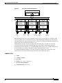
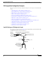
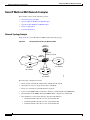
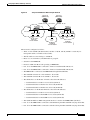
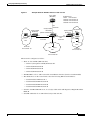
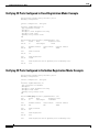
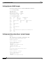
Configuring Routing Between VLANs
First Published: March 15, 2006
Last Updated: October 10, 2008
This module provides an overview of VLANs. It describes the encapsulation protocols used for routing
between VLANs and provides some basic information about designing VLANs. This module contains
tasks for configuring routing between VLANS.
Finding Feature Information in This Module
Your Cisco IOS software release may not support all of the features documented in this module. To reach
links to specific feature documentation in this module and to see a list of the releases in which each feature is
supported, use the “Feature Information for Routing Between VLANs” section on page 71.
Finding Support Information for Platforms and Cisco IOS Software Images
Use Cisco Feature Navigator to find information about platform support and Cisco IOS software image
support. Access Cisco Feature Navigator at http://www.cisco.com/go/fn. You must have an account on
Cisco.com. If you do not have an account or have forgotten your username or password, click Cancel at
the login dialog box and follow the instructions that appear.
Contents
•
Information About Routing Between VLANs, page 2
•
How to Configure Routing Between VLANS, page 12
•
Configuration Examples for Configuring Routing Between VLANs, page 52
•
Additional References, page 70
•
Feature Information for Routing Between VLANs, page 71
Americas Headquarters:
Cisco Systems, Inc., 170 West Tasman Drive, San Jose, CA 95134-1706 USA
© 2007, 2008 Cisco Systems, Inc. All rights reserved.
Configuring Routing Between VLANs
Information About Routing Between VLANs
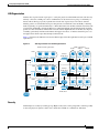
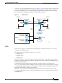
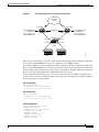
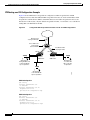
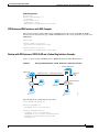
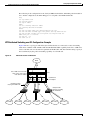
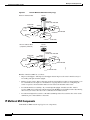
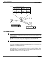
Information About Routing Between VLANs
This module describes routing between VLANs. It contains the following sections:
•
Virtual Local Area Network Definition, page 2
•
VLAN Performance, page 4
•
VLAN Colors, page 8
•
Implementing VLANS, page 9
•
Communication Between VLANs, page 9
•
VLAN Interoperability, page 11
•
Designing Switched VLANs, page 12
Virtual Local Area Network Definition
A virtual local area network (VLAN) is a switched network that is logically segmented on an
organizational basis, by functions, project teams, or applications rather than on a physical or
geographical basis. For example, all workstations and servers used by a particular workgroup team can
be connected to the same VLAN, regardless of their physical connections to the network or the fact that
they might be intermingled with other teams. Reconfiguration of the network can be done through
software rather than by physically unplugging and moving devices or wires.
A VLAN can be thought of as a broadcast domain that exists within a defined set of switches. A VLAN
consists of a number of end systems, either hosts or network equipment (such as bridges and routers),
connected by a single bridging domain. The bridging domain is supported on various pieces of network
equipment; for example, LAN switches that operate bridging protocols between them with a separate
bridge group for each VLAN.
VLANs are created to provide the segmentation services traditionally provided by routers in LAN
configurations. VLANs address scalability, security, and network management. Routers in VLAN
topologies provide broadcast filtering, security, address summarization, and traffic flow management.
None of the switches within the defined group will bridge any frames, not even broadcast frames,
between two VLANs. Several key issues described in the following sections need to be considered when
designing and building switched LAN internetworks:
2
•
LAN Segmentation, page 3
•
Security, page 3
•
Broadcast Control, page 4
•
VLAN Performance, page 4
•
Network Management, page 4
•
Network Monitoring Using SNMP, page 4
•
Communication Between VLANs
•
Relaying Function, page 4
•
Native VLAN, page 6
•
PVST+, page 7
•
Ingress and Egress Rules, page 8
•
Integrated Routing and Bridging, page 8
Configuring Routing Between VLANs
Information About Routing Between VLANs
LAN Segmentation
VLANs allow logical network topologies to overlay the physical switched infrastructure such that any
arbitrary collection of LAN ports can be combined into an autonomous user group or community of
interest. The technology logically segments the network into separate Layer 2 broadcast domains
whereby packets are switched between ports designated to be within the same VLAN. By containing
traffic originating on a particular LAN only to other LANs in the same VLAN, switched virtual networks
avoid wasting bandwidth, a drawback inherent to traditional bridged and switched networks in which
packets are often forwarded to LANs with no need for them. Implementation of VLANs also improves
scalability, particularly in LAN environments that support broadcast- or multicast-intensive protocols
and applications that flood packets throughout the network.
Figure 73 illustrates the difference between traditional physical LAN segmentation and logical VLAN
segmentation.
Figure 73
LAN Segmentation and VLAN Segmentation
Traditional LAN segmentation
VLAN segmentation
VLAN 1
VLAN 2
VLAN 3
LAN 1
Catalyst
VLAN switch
Shared hub
Floor 3
LAN 2
Catalyst
VLAN switch
Shared hub
Floor 2
LAN 3
Router
Floor 1
Catalyst
VLAN switch
S6619
Shared hub
Security
VLANs improve security by isolating groups. High-security users can be grouped into a VLAN, possibly
on the same physical segment, and no users outside that VLAN can communicate with them.
3
Configuring Routing Between VLANs
Information About Routing Between VLANs
Broadcast Control
Just as switches isolate collision domains for attached hosts and only forward appropriate traffic out a
particular port, VLANs provide complete isolation between VLANs. A VLAN is a bridging domain, and
all broadcast and multicast traffic is contained within it.
VLAN Performance
The logical grouping of users allows an accounting group to make intensive use of a networked
accounting system assigned to a VLAN that contains just that accounting group and its servers.
That group’s work will not affect other users. The VLAN configuration improves general network
performance by not slowing down other users sharing the network.
Network Management
The logical grouping of users allows easier network management. It is not necessary to pull cables to
move a user from one network to another. Adds, moves, and changes are achieved by configuring a port
into the appropriate VLAN.
Network Monitoring Using SNMP
SNMP support has been added to provide mib-2 interfaces sparse table support for Fast Ethernet
subinterfaces. Monitor your VLAN subinterface using the show vlans EXEC command. For more
information on configuring SNMP on your Cisco network device or enabling an SNMP agent for remote
access, refer to the “Configuring SNMP” chapter in the Cisco IOS Configuration Fundamentals
Configuration Guide.
Communication Between VLANs
Communication between VLANs is accomplished through routing, and the traditional security and
filtering functions of the router can be used. Cisco IOS software provides network services such as
security filtering, quality of service (QoS), and accounting on a per-VLAN basis. As switched networks
evolve to distributed VLANs, Cisco IOS software provides key inter-VLAN communications and allows
the network to scale.
Before Cisco IOS Release 12.2, Cisco IOS support for interfaces that have 802.1Q encapsulation
configured is IP, IP multicast, and IPX routing between respective VLANs represented as subinterfaces
on a link. New functionality has been added in IEEE 802.1Q support for bridging on those interfaces and
the capability to configure and use integrated routing and bridging (IRB).
Relaying Function
The relaying function level, as displayed in Figure 74, is the lowest level in the architectural model
described in the IEEE 802.1Q standard and presents three types of rules:
4
•
Ingress rules—Rules relevant to the classification of received frames belonging to a VLAN.
•
Forwarding rules between ports—Rules decide whether to filter or forward the frame.
•
Egress rules (output of frames from the switch)—Rules decide if the frame must be sent tagged or
untagged.
Configuring Routing Between VLANs
Information About Routing Between VLANs
Figure 74
Relaying Function
Port state
information
Forwarding
process
Port state
information
Ingress
rules
Filtering
database
Egress
rules
Frame
transmission
54713
Frame
reception
The Tagging Scheme
Figure 75 shows the tagging scheme proposed by the 802.3ac standard, that is, the addition of the four
octets after the source MAC address. Their presence is indicated by a particular value of the EtherType
field (called TPID), which has been fixed to be equal to 0x8100. When a frame has the EtherType equal
to 0x8100, this frame carries the tag IEEE 802.1Q/802.1p. The tag is stored in the following two octets
and it contains 3 bits of user priority, 1 bit of Canonical Format Identifier (CFI), and 12 bits of VLAN
ID (VID). The 3 bits of user priority are used by the 802.1p standard; the CFI is used for compatibility
reasons between Ethernet-type networks and Token Ring-type networks. The VID is the identification
of the VLAN, which is basically used by the 802.1Q standard; being on 12 bits, it allows the
identification of 4096 VLANs.
After the two octets of TPID and the two octets of the Tag Control Information field there are two octets
that originally would have been located after the Source Address field where there is the TPID. They
contain either the MAC length in the case of IEEE 802.3 or the EtherType in the case of Ethernet
version 2.
5
Configuring Routing Between VLANs
Information About Routing Between VLANs
Figure 75
Tagging Scheme
User
priority
6
Destination address
6
Source address
2
EtherType = 0x8100
2
Tag control information
2
MAC length/type
CFI
VID (VLAN ID) - 12 bits
Data
Variable
4
54712
PAD
FCS
The EtherType and VLAN ID are inserted after the MAC source address, but before the original
Ethertype/Length or Logical Link Control (LLC). The 1-bit CFI included a T-R Encapsulation bit so that
Token Ring frames can be carried across Ethernet backbones without using 802.1H translation.
Frame Control Sequence Recomputation
Figure 76 shows how adding a tag in a frame recomputes the Frame Control Sequence. 802.1p and
802.1Q share the same tag.
Adding a Tag Recomputes the Frame Control Sequence
Dest
Src
Dest
Src
PRI
Len/Etype
Etype
Data
Tag
FCS
Len/Etype
VLAN ID
Token ring encapsulation flag
Original
frame
Data
FCS
(VLAN ID and
TR encapsulations
are 802.1Q,
not 802.1p)
Tagged
frame
54711
Figure 76
Native VLAN
Each physical port has a parameter called PVID. Every 802.1Q port is assigned a PVID value that is of
its native VLAN ID (default is VLAN 1). All untagged frames are assigned to the LAN specified in the
PVID parameter. When a tagged frame is received by a port, the tag is respected. If the frame is untagged,
the value contained in the PVID is considered as a tag. Because the frame is untagged and the PVID is
tagged to allow the coexistence, as shown in Figure 77, on the same pieces of cable of VLAN-aware
bridge/stations and of VLAN-unaware bridges/stations. Consider, for example, the two stations
6
Configuring Routing Between VLANs
Information About Routing Between VLANs
connected to the central trunk link in the lower part of Figure 77. They are VLAN-unaware and they will
be associated to the VLAN C, because the PVIDs of the VLAN-aware bridges are equal to VLAN C.
Because the VLAN-unaware stations will send only untagged frames, when the VLAN-aware bridge
devices receive these untagged frames they will assign them to VLAN C.
Figure 77
Native VLAN
VLAN A
VLAN A
PVID = A
VLAN-aware
bridge
VLAN-aware
bridge
Access
ports
PVID = C
VLAN B
PVID = C
Access
ports
PVID = C
PVID = B
PVID = A
PVID = B
VLAN B
Trunk
link
VLAN C
VLAN-unaware
end station
VLAN-unaware
end station
VLAN-unaware
end station
VLAN B
VLAN-aware
end station
54710
PVID = C
VLAN C
PVST+
PVST+ provides support for 802.1Q trunks and the mapping of multiple spanning trees to the single
spanning tree of 802.1Q switches.
The PVST+ architecture distinguishes three types of regions:
•
A PVST region
•
A PVST+ region
•
A MST region
Each region consists of a homogenous type of switch. A PVST region can be connected to a PVST+
region by connecting two ISL ports. Similarly, a PVST+ region can be connected to an MST region by
connecting two 802.1Q ports.
At the boundary between a PVST region and a PVST+ region the mapping of spanning trees is
one-to-one. At the boundary between a MST region and a PVST+ region, the ST in the MST region maps
to one PVST in the PVST+ region. The one it maps to is called the common spanning tree (CST). The
default CST is the PVST of VLAN 1 (Native VLAN).
All PVSTs, except for the CST, are tunneled through the MST region. Tunneling means that bridge
protocol data units (BPDUs) are flooded through the MST region along the single spanning tree present
in the MST region.
7
Configuring Routing Between VLANs
Information About Routing Between VLANs
Ingress and Egress Rules
The BPDU transmission on the 802.1Q port of a PVST+ router will be implemented in compliance with
the following rules:
•
The CST BPDU (of VLAN 1, by default) is sent to the IEEE address.
•
All the other BPDUs are sent to Shared Spanning Tree Protocol (SSTP)-Address and encapsulated
with Logical Link Control-Subnetwork Access Protocol (LLC-SNAP) header.
•
The BPDU of the CST and BPDU of the VLAN equal to the PVID of the 802.1Q trunk are sent
untagged.
•
All other BPDUs are sent tagged with the VLAN ID.
•
The CST BPDU is also sent to the SSTP address.
•
Each SSTP-addressed BPDU is also tailed by a Tag-Length-Value for the PVID checking.
The BPDU reception on the 802.1Q port of a PVST+ router will follow these rules:
•
All untagged IEEE addressed BPDUs must be received on the PVID of the 802.1Q port.
•
The IEEE addressed BPDUs whose VLAN ID matches the Native VLAN are processed by CST.
•
All the other IEEE addressed BPDUs whose VLAN ID does not match the Native VLAN and whose
port type is not of 802.1Q are processed by the spanning tree of that particular VLAN ID.
•
The SSTP addressed BPDU whose VLAN ID is not equal to the TLV are dropped and the ports are
blocked for inconsistency.
•
All the other SSTP addressed BPDUs whose VLAN ID is not equal to the Native VLAN are
processed by the spanning tree of that particular VLAN ID.
•
The SSTP addressed BPDUs whose VLAN ID is equal to the Native VLAN are dropped. It is used
for consistency checking.
Integrated Routing and Bridging
IRB enables a user to route a given protocol between routed interfaces and bridge groups or route a given
protocol between the bridge groups. Integrated routing and bridging is supported on the following
protocols:
•
IP
•
IPX
•
AppleTalk
VLAN Colors
VLAN switching is accomplished through frame tagging where traffic originating and contained within
a particular virtual topology carries a unique VLAN ID as it traverses a common backbone or trunk link.
The VLAN ID enables VLAN switching devices to make intelligent forwarding decisions based on the
embedded VLAN ID. Each VLAN is differentiated by a color, or VLAN identifier. The unique VLAN
ID determines the frame coloring for the VLAN. Packets originating and contained within a particular
VLAN carry the identifier that uniquely defines that VLAN (by the VLAN ID).
The VLAN ID allows VLAN switches and routers to selectively forward packets to ports with the same
VLAN ID. The switch that receives the frame from the source station inserts the VLAN ID and the
packet is switched onto the shared backbone network. When the frame exits the switched LAN, a switch
8
Configuring Routing Between VLANs
Information About Routing Between VLANs
strips the header and forwards the frame to interfaces that match the VLAN color. If you are using a
Cisco network management product such as VlanDirector, you can actually color code the VLANs and
monitor VLAN graphically.
Implementing VLANS
Network managers can logically group networks that span all major topologies, including high-speed
technologies such as, ATM, FDDI, and Fast Ethernet. By creating virtual LANs, system and network
administrators can control traffic patterns and react quickly to relocations and keep up with constant
changes in the network due to moving requirements and node relocation just by changing the VLAN
member list in the router configuration. They can add, remove, or move devices or make other changes
to network configuration using software to make the changes.
Issues regarding creating VLANs should have been addressed when you developed your network design.
Issues to consider include the following:
•
Scalability
•
Performance improvements
•
Security
•
Network additions, moves, and changes
Communication Between VLANs
Cisco IOS software provides full-feature routing at Layer 3 and translation at Layer 2 between VLANs.
Five different protocols are available for routing between VLANs:
•
Inter-Switch Link Protocol, page 9
•
IEEE 802.10 Protocol, page 10
•
IEEE 802.1Q Protocol, page 10
•
ATM LANE Protocol, page 10
•
ATM LANE Fast Simple Server Replication Protocol, page 10
All five of these technologies are based on OSI Layer 2 bridge multiplexing mechanisms.
Inter-Switch Link Protocol
The Inter-Switch Link (ISL) protocol is used to interconnect two VLAN-capable Ethernet, Fast Ethernet,
or Gigabit Ethernet devices, such as the Catalyst 3000 or 5000 switches and Cisco 7500 routers. The ISL
protocol is a packet-tagging protocol that contains a standard Ethernet frame and the VLAN information
associated with that frame. The packets on the ISL link contain a standard Ethernet, FDDI, or Token Ring
frame and the VLAN information associated with that frame. ISL is currently supported only over Fast
Ethernet links, but a single ISL link, or trunk, can carry different protocols from multiple VLANs.
Procedures for configuring ISL and Token Ring ISL (TRISL) features are provided in “Configuring
Routing Between VLANs with Inter-Switch Link Encapsulation” section on page 15.
9
Configuring Routing Between VLANs
Information About Routing Between VLANs
IEEE 802.10 Protocol
The IEEE 802.10 protocol provides connectivity between VLANs. Originally developed to address the
growing need for security within shared LAN/MAN environments, it incorporates authentication and
encryption techniques to ensure data confidentiality and integrity throughout the network. Additionally,
by functioning at Layer 2, it is well suited to high-throughput, low-latency switching environments. The
IEEE 802.10 protocol can run over any LAN or HDLC serial interface.
Procedures for configuring routing between VLANs with IEEE 802.10 encapsulation are provided in the
“Configuring Routing Between VLANs with IEEE 802.10 Encapsulation” section on page 31.
IEEE 802.1Q Protocol
The IEEE 802.1Q protocol is used to interconnect multiple switches and routers, and for defining VLAN
topologies. Cisco currently supports IEEE 802.1Q for Fast Ethernet and Gigabit Ethernet interfaces.
Note
Cisco does not support IEEE 802.1Q encapsulation for Ethernet interfaces.
Procedures for configuring routing between VLANs with IEEE 802.1Q encapsulation are provided in
the “Configuring Routing Between VLANs with IEEE 802.1Q Encapsulation” section on page 34.
ATM LANE Protocol
The ATM LAN Emulation (LANE) protocol provides a way for legacy LAN users to take advantage of
ATM benefits without requiring modifications to end-station hardware or software. LANE emulates a
broadcast environment like IEEE 802.3 Ethernet on top of an ATM network that is a point-to-point
environment.
LANE makes ATM function like a LAN. LANE allows standard LAN drivers like NDIS and ODI to be
used. The virtual LAN is transparent to applications. Applications can use normal LAN functions
without the underlying complexities of the ATM implementation. For example, a station can send
broadcasts and multicasts, even though ATM is defined as a point-to-point technology and does not
support any-to-any services.
To accomplish this, special low-level software is implemented on an ATM client workstation, called the
LAN Emulation Client (LEC). The client software communicates with a central control point called a
LAN Emulation Server (LES). A broadcast and unknown server (BUS) acts as a central point to
distribute broadcasts and multicasts. The LAN Emulation Configuration Server (LECS) holds a database
of LECs and the ELANs they belong to. The database is maintained by a network administrator.
These protocols are described in detail in the Cisco Internetworking Design Guide.
ATM LANE Fast Simple Server Replication Protocol
To improve the ATM LANE Simple Server Replication Protocol (SSRP), Cisco introduced the ATM
LANE Fast Simple Server Replication Protocol (FSSRP). FSSRP differs from LANE SSRP in that all
configured LANE servers of an ELAN are always active. FSSRP-enabled LANE clients have virtual
circuits (VCs) established to a maximum of four LANE servers and BUSs at one time. If a single LANE
server goes down, the LANE client quickly switches over to the next LANE server and BUS, resulting
in no data or LE ARP table entry loss and no extraneous signalling.
10
Configuring Routing Between VLANs
Information About Routing Between VLANs
The FSSRP feature improves upon SSRP such that LANE server and BUS switchover for LANE clients
is immediate. With SSRP, a LANE server would go down, and depending on the network load, it may
have taken considerable time for the LANE client to come back up joined to the correct LANE server
and BUS. In addition to going down with SSRP, the LANE client would do the following:
•
Clear out its data direct VCs
•
Clear out its LE ARP entries
•
Cause substantial signalling activity and data loss
FSSRP was designed to alleviate these problems with the LANE client. With FSSRP, each LANE client
is simultaneously joined to up to four LANE servers and BUSs. The concept of the master LANE server
and BUS is maintained; the LANE client uses the master LANE server when it needs LANE server BUS
services. However, the difference between SSRP and FSSRP is that if and when the master LANE server
goes down, the LANE client is already connected to multiple backup LANE servers and BUSs. The
LANE client simply uses the next backup LANE server and BUS as the master LANE server and BUS.
VLAN Interoperability
Cisco IOS features bring added benefits to the VLAN technology. Enhancements to ISL, IEEE 802.10,
and ATM LANE implementations enable routing of all major protocols between VLANs. These
enhancements allow users to create more robust networks incorporating VLAN configurations by
providing communications capabilities between VLANs.
Inter-VLAN Communications
The Cisco IOS supports full routing of several protocols over ISL and ATM LANE VLANs. IP, Novell
IPX, and AppleTalk routing are supported over IEEE 802.10 VLANs. Standard routing attributes such
as network advertisements, secondaries, and help addresses are applicable, and VLAN routing is fast
switched. Table 39 shows protocols supported for each VLAN encapsulation format and corresponding
Cisco IOS software releases.
Table 39
Inter-VLAN Routing Protocol Support
Protocol
ISL
ATM LANE
IEEE 802.10
IP
Release 11.1
Release 10.3
Release 11.1
Novell IPX (default
encapsulation)
Release 11.1
Release 10.3
Release 11.1
Novell IPX (configurable
encapsulation)
Release 11.3
Release 10.3
Release 11.3
AppleTalk Phase II
Release 11.3
Release 10.3
—
DECnet
Release 11.3
Release 11.0
—
Banyan VINES
Release 11.3
Release 11.2
—
XNS
Release 11.3
Release 11.2
—
CLNS
Release 12.1
—
—
IS-IS
Release 12.1
—
—
11
Configuring Routing Between VLANs
How to Configure Routing Between VLANS
VLAN Translation
VLAN translation refers to the ability of the Cisco IOS software to translate between different VLANs
or between VLAN and non-VLAN encapsulating interfaces at Layer 2. Translation is typically used for
selective inter-VLAN switching of nonroutable protocols and to extend a single VLAN topology across
hybrid switching environments. It is also possible to bridge VLANs on the main interface; the VLAN
encapsulating header is preserved. Topology changes in one VLAN domain do not affect a different
VLAN.
Designing Switched VLANs
By the time you are ready to configure routing between VLANs, you will have already defined them
through the switches in your network. Issues related to network design and VLAN definition should be
addressed during your network design. Refer to the Cisco Internetworking Design Guide and appropriate
switch documentation for information on these topics:
•
Sharing resources between VLANs
•
Load balancing
•
Redundant links
•
Addressing
•
Segmenting networks with VLANs—Segmenting the network into broadcast groups improves
network security. Use router access lists based on station addresses, application types, and protocol
types.
•
Routers and their role in switched networks—In switched networks, routers perform broadcast
management, route processing, and distribution, and provide communication between VLANs.
Routers provide VLAN access to shared resources and connect to other parts of the network that are
either logically segmented with the more traditional subnet approach or require access to remote
sites across wide-area links.
How to Configure Routing Between VLANS
This section contains the following configuration procedure groups:
•
Configuring a VLAN Range, page 12
•
Configuring Routing Between VLANs with Inter-Switch Link Encapsulation
•
Configuring Routing Between VLANs with IEEE 802.10 Encapsulation
•
Configuring Routing Between VLANs with IEEE 802.1Q Encapsulation
•
Configuring IEEE 802.1Q-in-Q VLAN Tag Termination
Configuring a VLAN Range
Using the VLAN Range feature, you can group VLAN subinterfaces together so that any command
entered in a group applies to every subinterface within the group. This capability simplifies
configurations and reduces command parsing.
12
Configuring Routing Between VLANs
How to Configure Routing Between VLANS
Restrictions
•
Each command you enter while you are in interface configuration mode with the interface range
command is executed as it is entered. The commands are not batched together for execution after
you exit interface configuration mode. If you exit interface configuration mode while the commands
are being executed, some commands might not be executed on some interfaces in the range. Wait
until the command prompt reappears before exiting interface configuration mode.
•
The no interface range command is not supported. You must delete individual subinterfaces to
delete a range.
Supported Platforms
For Cisco IOS Release 12.2(13)T, the following platforms are supported:
•
Cisco 6400 series
•
Cisco 7200 series
•
Cisco 7401 ASR router
Benefits
The VLAN Range feature provides the following benefits:
Simultaneous Configurations
Identical commands can be entered once for a range of subinterfaces, rather than being entered
separately for each subinterface.
Overlapping Range Configurations
Overlapping ranges of subinterfaces can be configured.
Customized Subinterfaces
Individual subinterfaces within a range can be customized or deleted.
Configuring a Range of VLAN Subinterfaces
Use the following commands to configure a range of VLAN subinterfaces.
SUMMARY STEPS
1.
enable
2.
configure terminal
3.
interface range {{ethernet | fastethernet | gigabitethernet | atm}
fastethernet | gigabitethernet |
atm}slot/interface.subinterface}]
slot/interface.subinterface - {{ethernet |
4.
encapsulation dot1Q vlan-id
5.
no shutdown
6.
exit
7.
show running-config
13
Configuring Routing Between VLANs
How to Configure Routing Between VLANS
8.
show interfaces
DETAILED STEPS
Step 1
Command
Purpose
enable
Enables privileged EXEC mode.
•
Enter your password if prompted.
Example:
Router> enable
Step 2
configure terminal
Enters global configuration mode.
Example:
Router# configure terminal
Step 3
interface range {{ethernet | fastethernet |
gigabitethernet | atm} slot/interface.subinterface {{ethernet | fastethernet | gigabitethernet |
atm}slot/interface.subinterface}
Selects the range of subinterfaces to be configured.
Note
Example:
The spaces around the dash are required. For
example, the command interface range
fastethernet 1 - 5 is valid; the command
interface range fastethernet 1-5 is not valid.
Router(config)# interface range fastethernet5/1.1 fastethernet5/1.4
Step 4
encapsulation dot1Q vlan-id
Example:
Applies a unique VLAN ID to each subinterface
within the range.
•
vlan-id—Virtual LAN identifier. The allowed
range is from 1 to 4095.
•
The VLAN ID specified by the vlan-id argument
is applied to the first subinterface in the range.
Each subsequent interface is assigned a VLAN
ID, which is the specified vlan-id plus the
subinterface number minus the first subinterface
number (VLAN ID + subinterface number – first
subinterface number).
Router(config-if)# encapsulation dot1Q 301
Step 5
no shutdown
Activates the interface.
•
Example:
This command is required only if you shut down
the interface.
Router(config-if)# no shutdown
Step 6
exit
Example:
Router(config-if)# exit
14
Returns to privileged EXEC mode.
Configuring Routing Between VLANs
How to Configure Routing Between VLANS
Step 7
Command
Purpose
show running-config
Verifies subinterface configuration.
Example:
Router# show running-config
Step 8
Verifies that subinterfaces have been created.
show interfaces
Example:
Router# show interfaces
Configuring Routing Between VLANs with Inter-Switch Link Encapsulation
This section describes the Inter-Switch Link (ISL) protocol and provides guidelines for configuring ISL
and Token Ring ISL (TRISL) features. This section contains the following:
•
Frame Tagging in ISL, page 15
•
Configuring AppleTalk Routing over ISL, page 16
•
Configuring Banyan VINES Routing over ISL, page 18
•
Configuring DECnet Routing over ISL, page 19
•
Configuring the Hot Standby Router Protocol over ISL, page 20
•
Configuring IP Routing over TRISL, page 22
•
Configuring IPX Routing on 802.10 VLANs over ISL, page 23
•
Configuring IPX Routing over TRISL, page 25
•
Configuring VIP Distributed Switching over ISL, page 26
•
Configuring XNS Routing over ISL, page 28
•
Configuring CLNS Routing over ISL, page 29
•
Configuring IS-IS Routing over ISL, page 30
Frame Tagging in ISL
ISL is a Cisco protocol for interconnecting multiple switches and maintaining VLAN information as
traffic goes between switches. ISL provides VLAN capabilities while maintaining full wire speed
performance on Fast Ethernet links in full- or half-duplex mode. ISL operates in a point-to-point
environment and will support up to 1000 VLANs. You can define virtually as many logical networks as
are necessary for your environment.
With ISL, an Ethernet frame is encapsulated with a header that transports VLAN IDs between switches
and routers. A 26-byte header that contains a 10-bit VLAN ID is propounded to the Ethernet frame.
A VLAN ID is added to the frame only when the frame is prepended for a nonlocal network. Figure 78
shows VLAN packets traversing the shared backbone. Each VLAN packet carries the VLAN ID within
the packet header.
15
Configuring Routing Between VLANs
How to Configure Routing Between VLANS
Figure 78
VLAN Packets Traversing the Shared Backbone
Green
Green
Fast Ethernet
Token
Ring
Red
Green
Blue
Blue
Red
Red
Token
Ring
S6621
Blue
You can configure routing between any number of VLANs in your network. This section documents the
configuration tasks for each protocol supported with ISL encapsulation. The basic process is the same,
regardless of the protocol being routed. It involves the following tasks:
•
Enabling the protocol on the router
•
Enabling the protocol on the interface
•
Defining the encapsulation format as ISL or TRISL
•
Customizing the protocol according to the requirements for your environment
Configuring AppleTalk Routing over ISL
AppleTalk can be routed over VLAN subinterfaces using the ISL and IEEE 802.10 VLAN
encapsulation protocols. The AppleTalk Routing over ISL and IEEE 802.10 Virtual LANs feature
provides full-feature Cisco IOS software AppleTalk support on a per-VLAN basis, allowing standard
AppleTalk capabilities to be configured on VLANs.
To route AppleTalk over ISL or IEEE 802.10 between VLANs, you need to customize the subinterface
to create the environment in which it will be used. Perform the steps in the order in which they appear.
SUMMARY STEPS
1.
enable
2.
configure terminal
3.
appletalk routing [eigrp router-number]
4.
interface type slot/port.subinterface-number
5.
encapsulation isl vlan-identifier
or
encapsulation sde said
16
6.
appletalk cable-range cable-range [network.node]
7.
appletalk zone zone-name
Configuring Routing Between VLANs
How to Configure Routing Between VLANS
DETAILED STEPS
Step 1
Command or Action
Purpose
enable
Enables privileged EXEC mode.
•
Enter your password if prompted.
Example:
Router> enable
Step 2
Enters global configuration mode.
configure terminal
Example:
Router# configure terminal
Step 3
appletalk routing [eigrp router-number]
Enables AppleTalk routing globally on either ISL or 802.10
interfaces.
Example:
Router(config)# appletalk routing
Step 4
interface type slot/port.subinterface-number
Specifies the subinterface the VLAN will use.
Example:
Router(config)# interface Fddi 1/0.100
Step 5
encapsulation isl vlan-identifier
or
Defines the encapsulation format as either ISL (isl) or IEEE
802.10 (sde), and specifies the VLAN identifier or security
association identifier, respectively.
encapsulation sde said
Example:
Router(config-if)#
Step 6
encapsulation sde 100
appletalk cable-range cable-range
[network.node]
Assigns the AppleTalk cable range and zone for the
subinterface.
Example:
Router(config-if)#
100-100 100.2
Step 7
appletalk cable-range
appletalk zone zone-name
Assigns the AppleTalk zone for the subinterface.
Example:
Router(config-if)# appletalk zone 100
17
Configuring Routing Between VLANs
How to Configure Routing Between VLANS
Configuring Banyan VINES Routing over ISL
Banyan VINES can be routed over VLAN subinterfaces using the ISL encapsulation protocol. The
Banyan VINES Routing over ISL Virtual LANs feature provides full-feature Cisco IOS software Banyan
VINES support on a per-VLAN basis, allowing standard Banyan VINES capabilities to be configured
on VLANs.
To route Banyan VINES over ISL between VLANs, you need to configure ISL encapsulation on the
subinterface. Perform the steps in the following task in the order in which they appear:
SUMMARY STEPS
1.
enable
2.
configure terminal
3.
vines routing [address]
4.
interface type slot/port.subinterface-number
5.
encapsulation isl vlan-identifier
6.
vines metric [whole [fraction]]
DETAILED STEPS
Step 1
Command or Action
Purpose
enable
Enables privileged EXEC mode.
•
Enter your password if prompted.
Example:
Router> enable
Step 2
configure terminal
Enters global configuration mode.
Example:
Router# configure terminal
Step 3
vines routing [address]
Enables Banyan VINES routing globally.
Example:
Router(config)# vines routing
Step 4
interface type slot/port.subinterface-number
Specifies the subinterface on which ISL will be used.
Example:
Router(config)# interface fastethernet 1/0.1
Step 5
encapsulation isl vlan-identifier
Defines the encapsulation format as ISL (isl), and specifies
the VLAN identifier.
Example:
Router(config-if)# encapsulation isl 200
Step 6
vines metric [whole [fraction]]
Example:
Router(config-if)#vines metric 2
18
Enables VINES routing metric on an interface.
Configuring Routing Between VLANs
How to Configure Routing Between VLANS
Configuring DECnet Routing over ISL
DECnet can be routed over VLAN subinterfaces using the ISL VLAN encapsulation protocols. The
DECnet Routing over ISL Virtual LANs feature provides full-feature Cisco IOS software DECnet
support on a per-VLAN basis, allowing standard DECnet capabilities to be configured on VLANs.
To route DECnet over ISL VLANs, you need to configure ISL encapsulation on the subinterface.
Perform the steps described in the following task in the order in which they appear.
SUMMARY STEPS
1.
enable
2.
configure terminal
3.
decnet [network-number] routing [decnet-address]
4.
interface type slot/port.subinterface-number
5.
encapsulation isl vlan-identifier
6.
decnet cost [cost-value]
DETAILED STEPS
Step 1
Command or Action
Purpose
enable
Enables privileged EXEC mode.
•
Enter your password if prompted.
Example:
Router> enable
Step 2
configure terminal
Enters global configuration mode.
Example:
Router# configure terminal
Step 3
Router(config)# decnet [network-number] routing
[decnet-address]
Enables DECnet on the router.
Example:
Router(config)# decnet routing 2.1
Step 4
interface type slot/port.subinterface-number
Specifies the subinterface on which ISL will be used.
Example:
Router(config)# interface fastethernet 1/0.1
Step 5
encapsulation isl vlan-identifier
Defines the encapsulation format as ISL (isl), and specifies
the VLAN identifier.
Example:
Router(config-if)# encapsulation isl 200
Step 6
decnet cost [cost-value]
Enables DECnet cost metric on an interface.
Example:
Router(config-if)# decnet cost 4
19
Configuring Routing Between VLANs
How to Configure Routing Between VLANS
Configuring the Hot Standby Router Protocol over ISL
The Hot Standby Router Protocol (HSRP) provides fault tolerance and enhanced routing performance
for IP networks. HSRP allows Cisco IOS routers to monitor each other’s operational status and very
quickly assume packet forwarding responsibility in the event the current forwarding device in the HSRP
group fails or is taken down for maintenance. The standby mechanism remains transparent to the
attached hosts and can be deployed on any LAN type. With multiple Hot Standby groups, routers can
simultaneously provide redundant backup and perform loadsharing across different IP subnets.
Figure 79 illustrates HSRP in use with ISL providing routing between several VLANs.
Figure 79
Hot Standby Router Protocol in VLAN Configurations
Cisco IOS
router
ISL
ISL
ISL
Cisco VLAN
switch
VLAN 10
VLAN 30
Cisco VLAN
switch
VLAN 20
VLAN 10
VLAN 40
S6620
VLAN 20
Cisco IOS
router
HSRP
A separate HSRP group is configured for each VLAN subnet so that Cisco IOS router A can be the
primary and forwarding router for VLANs 10 and 20. At the same time, it acts as backup for VLANs 30
and 40. Conversely, Router B acts as the primary and forwarding router for ISL VLANs 30 and 40, as
well as the secondary and backup router for distributed VLAN subnets 10 and 20.
Running HSRP over ISL allows users to configure redundancy between multiple routers that are
configured as front ends for VLAN IP subnets. By configuring HSRP over ISLs, users can eliminate
situations in which a single point of failure causes traffic interruptions. This feature inherently provides
some improvement in overall networking resilience by providing load balancing and redundancy
capabilities between subnets and VLANs.
To configure HSRP over ISLs between VLANs, you need to create the environment in which it will be
used. Perform the tasks described in the following sections in the order in which they appear.
SUMMARY STEPS
20
1.
enable
2.
configure terminal
3.
interface type slot/port.subinterface-number
Configuring Routing Between VLANs
How to Configure Routing Between VLANS
4.
encapsulation isl vlan-identifier
5.
ip address ip-address mask [secondary]
6.
standby [group-number] ip [ip-address [secondary]]
7.
standby [group-number] timers hellotime holdtime
8.
standby [group-number] priority priority
9.
standby [group-number] preempt
10. standby [group-number] track type-number [interface-priority]
11. standby [group-number] authentication string
DETAILED STEPS
Step 1
Command or Action
Purpose
enable
Enables privileged EXEC mode.
•
Enter your password if prompted.
Example:
Router> enable
Step 2
Enters global configuration mode.
configure terminal
Example:
Router# configure terminal
Step 3
Router(config)# interface type
slot/port.subinterface-number
Specifies the subinterface on which ISL will be used.
Example:
Router(config)# interface FastEthernet 1/1.110
Step 4
encapsulation isl vlan-identifier
Defines the encapsulation format, and specifies the VLAN
identifier.
Example:
Router(config-if)#
Step 5
encapsulation isl 110
ip address ip-address mask [secondary]
Specifies the IP address for the subnet on which ISL will be
used.
Example:
Router(config-if)# ip address 10.1.1.2
255.255.255.0
Step 6
Router(config-if)# standby [group-number] ip
[ip-address [secondary]]
Enables HSRP.
Example:
Router(config-if)# standby 1 ip 10.1.1.101
Step 7
Router(config-if)# standby [group-number]
timers hellotime holdtime
Configures the time between hello packets and the hold time
before other routers declare the active router to be down.
Example:
Router(config-if)# standby 1 timers 10 10
21
Configuring Routing Between VLANs
How to Configure Routing Between VLANS
Step 8
Command or Action
Purpose
Router(config-if)# standby [group-number]
priority priority
Sets the Hot Standby priority used to choose the active
router.
Example:
Router(config-if)# standby 1 priority 105
Step 9
Router(config-if)# standby [group-number]
preempt
Specifies that if the local router has priority over the current
active router, the local router should attempt to take its place
as the active router.
Example:
Router(config-if)# standby 1 priority 105
Step 10
Router(config-if)# standby [group-number] track
type-number [interface-priority]
Configures the interface to track other interfaces, so that if
one of the other interfaces goes down, the Hot Standby
priority for the device is lowered.
Example:
Router(config-if)# standby 1 track 4 5
Step 11
Router(config-if)# standby [group-number]
authentication string
Selects an authentication string to be carried in all HSRP
messages.
Example:
Router(config-if)# standby 1 authentication
hsrpword7
Note
For more information on HSRP, see the “Configuring IP Services” chapter in the Cisco IOS IP
Configuration Guide.
Configuring IP Routing over TRISL
The IP routing over TRISL VLANs feature extends IP routing capabilities to include support for routing
IP frame types in VLAN configurations.
SUMMARY STEPS
22
1.
enable
2.
configure terminal
3.
ip routing
4.
interface type slot/port.subinterface-number
5.
encapsulation tr-isl trbrf-vlan vlanid bridge-num bridge-number
6.
ip address ip-address mask
Configuring Routing Between VLANs
How to Configure Routing Between VLANS
DETAILED STEPS
Step 1
Command or Action
Purpose
enable
Enables privileged EXEC mode.
•
Enter your password if prompted.
Example:
Router> enable
Step 2
configure terminal
Enters global configuration mode.
Example:
Router# configure terminal
Step 3
Enables IP routing on the router.
ip routing
Example:
Router(config)# ip routing
Step 4
interface type slot/port.subinterface-number
Specifies the subinterface on which TRISL will be used.
Example:
Router(config# interface FastEthernet4/0.1
Step 5
encapsulation tr-isl trbrf-vlan vlanid
bridge-num bridge-number
Defines the encapsulation for TRISL.
•
Example:
Router(config-if# encapsulation tr-isl
trbrf-vlan 999 bridge-num 14
Step 6
ip address ip-address mask
The DRiP database is automatically enabled when
TRISL encapsulation is configured, and at least one
TrBRF is defined, and the interface is configured for
SRB or for routing with RIF
Sets a primary IP address for an interface.
•
Example:
Router(config-if# ip address 10.5.5.1
255.255.255.0
A mask identifies the bits that denote the network
number in an IP address. When you use the mask to
subnet a network, the mask is then referred to as a
subnet mask.
Note
TRISL encapsulation must be specified for a
subinterface before an IP address can be assigned to
that subinterface.
Configuring IPX Routing on 802.10 VLANs over ISL
The IPX Encapsulation for 802.10 VLAN feature provides configurable IPX (Novell-FDDI, SAP,
SNAP) encapsulation over 802.10 VLAN on router FDDI interfaces to connect the Catalyst 5000 VLAN
switch. This feature extends Novell NetWare routing capabilities to include support for routing all
standard IPX encapsulations for Ethernet frame types in VLAN configurations. Users with Novell
NetWare environments can now configure any one of the three IPX Ethernet encapsulations to be routed
using Secure Data Exchange (SDE) encapsulation across VLAN boundaries. IPX encapsulation options
now supported for VLAN traffic include the following:
•
Novell-FDDI (IPX FDDI RAW to 802.10 on FDDI)
•
SAP (IEEE 802.2 SAP to 802.10 on FDDI)
23
Configuring Routing Between VLANs
How to Configure Routing Between VLANS
•
SNAP (IEEE 802.2 SNAP to 802.10 on FDDI)
NetWare users can now configure consolidated VLAN routing over a single VLAN trunking
FDDI interface. Not all IPX encapsulations are currently supported for SDE VLAN. The IPX interior
encapsulation support can be achieved by messaging the IPX header before encapsulating in the SDE
format. Fast switching will also support all IPX interior encapsulations on non-MCI platforms (for
example non-AGS+ and non-7000). With configurable Ethernet encapsulation protocols, users have the
flexibility of using VLANs regardless of their NetWare Ethernet encapsulation. Configuring Novell IPX
encapsulations on a per-VLAN basis facilitates migration between versions of Netware. NetWare traffic
can now be routed across VLAN boundaries with standard encapsulation options (arpa, sap, and snap)
previously unavailable. Encapsulation types and corresponding framing types are described in the
“Configuring Novell IPX” chapter of the Cisco IOS AppleTalk and Novell IPX Configuration Guide.
Note
Only one type of IPX encapsulation can be configured per VLAN (subinterface). The IPX encapsulation
used must be the same within any particular subnet; a single encapsulation must be used by all NetWare
systems that belong to the same VLAN.
To configure Cisco IOS software on a router with connected VLANs to exchange different IPX framing
protocols, perform the steps described in the following task in the order in which they are appear.
SUMMARY STEPS
1.
enable
2.
configure terminal
3.
ipx routing [node]
4.
interface fddi slot/port.subinterface-number
5.
encapsulation sde vlan-identifier
6.
ipx network network encapsulation encapsulation-type
DETAILED STEPS
Step 1
Command or Action
Purpose
enable
Enables privileged EXEC mode.
•
Enter your password if prompted.
Example:
Router> enable
Step 2
configure terminal
Enters global configuration mode.
Example:
Router# configure terminal
Step 3
ipx routing [node]
Example:
Router(config)# ipx routing
24
Enables IPX routing globally.
Configuring Routing Between VLANs
How to Configure Routing Between VLANS
Step 4
Command or Action
Purpose
interface fddi slot/port.subinterface-number
Specifies the subinterface on which SDE will be used.
Example:
Router(config)# interface 2/0.1
Step 5
encapsulation sde vlan-identifier
Defines the encapsulation format and specifies the VLAN
identifier.
Example:
Router(config-if)# encapsulation isl 20
Step 6
ipx network network encapsulation
encapsulation-type
Specifies the IPX encapsulation among Novell-FDDI, SAP,
or SNAP.
Example:
Router(config-if)# ipx network 20 encapsulation
sap
Configuring IPX Routing over TRISL
The IPX Routing over ISL VLANs feature extends Novell NetWare routing capabilities to include
support for routing all standard IPX encapsulations for Ethernet frame types in VLAN configurations.
Users with Novell NetWare environments can configure either SAP or SNAP encapsulations to be routed
using the TRISL encapsulation across VLAN boundaries. The SAP (Novell Ethernet_802.2) IPX
encapsulation is supported for VLAN traffic.
NetWare users can now configure consolidated VLAN routing over a single VLAN trunking interface.
With configurable Ethernet encapsulation protocols, users have the flexibility of using VLANs
regardless of their NetWare Ethernet encapsulation. Configuring Novell IPX encapsulations on a
per-VLAN basis facilitates migration between versions of Netware. NetWare traffic can now be routed
across VLAN boundaries with standard encapsulation options (sap and snap) previously unavailable.
Encapsulation types and corresponding framing types are described in the “Configuring Novell IPX”
chapter of the Cisco IOS AppleTalk and Novell IPX Configuration Guide.
Note
Only one type of IPX encapsulation can be configured per VLAN (subinterface). The IPX encapsulation
used must be the same within any particular subnet: A single encapsulation must be used by all NetWare
systems that belong to the same LANs.
To configure Cisco IOS software to exchange different IPX framing protocols on a router with connected
VLANs, perform the steps in the following task in the order in which they are appear.
SUMMARY STEPS
1.
enable
2.
configure terminal
3.
ipx routing [node]
4.
interface type slot/port.subinterface-number
5.
encapsulation tr-isl trbrf-vlan trbrf-vlan bridge-num bridge-num
6.
ipx network network encapsulation encapsulation-type
25
Configuring Routing Between VLANs
How to Configure Routing Between VLANS
DETAILED STEPS
Step 1
Command or Action
Purpose
enable
Enables privileged EXEC mode.
•
Enter your password if prompted.
Example:
Router> enable
Step 2
configure terminal
Enters global configuration mode.
Example:
Router# configure terminal
Step 3
ipx routing [node]
Enables IPX routing globally.
Example:
Router(config)# source-bridge ring-group 100
Step 4
interface type slot/port.subinterface-number
Specifies the subinterface on which TRISL will be used.
Example:
Router(config-if)# interface TokenRing 3/1
Step 5
encapsulation tr-isl trbrf-vlan trbrf-vlan
bridge-num bridge-num
Defines the encapsulation for TRISL.
Example:
Router(config-if)#encapsulation tr-isl
trbrf-vlan 999 bridge-num 14
Step 6
ipx network network encapsulation
encapsulation-type
Specifies the IPX encapsulation on the subinterface by
specifying the NetWare network number (if necessary) and
the encapsulation type.
Example:
Router(config-if)# ipx network 100
encapsulation sap
Note
The default IPX encapsulation format for Cisco IOS routers is “novell-ether” (Novell Ethernet_802.3).
If you are running Novell Netware 3.12 or 4.0, the new Novell default encapsulation format is Novell
Ethernet_802.2 and you should configure the Cisco router with the IPX encapsulation format “sap.”
Configuring VIP Distributed Switching over ISL
With the introduction of the VIP distributed ISL feature, ISL encapsulated IP packets can be switched
on Versatile Interface Processor (VIP) controllers installed on Cisco 7500 series routers.
The second generation VIP2 provides distributed switching of IP encapsulated in ISL in VLAN
configurations. Where an aggregation route performs inter-VLAN routing for multiple VLANs, traffic
can be switched autonomously on-card or between cards rather than through the central Route Switch
Processor (RSP). Figure 80 shows the VIP distributed architecture of the Cisco 7500 series router.
26
Configuring Routing Between VLANs
How to Configure Routing Between VLANS
Figure 80
Cisco 7500 Distributed Architecture
Route Switch Processor
IP routing
table
IP forwarding
table
Versatile
Interface
Processor
Versatile
Interface
Processor
Versatile
Interface
Processor
Distributed IP
forwarding
cache
Distributed IP
forwarding
cache
Distributed IP
forwarding
cache
Fast
Fast
Ethernet Ethernet
Fast
Fast
Ethernet Ethernet
Fast
Fast
Ethernet Ethernet
VLAN
1,2,3
VLAN
4,5,6
VLAN
7,8,9
VLAN
VLAN
10,11,12 13,14,15
S6622
CyBus
VLAN
16,17,18
This distributed architecture allows incremental capacity increases by installation of additional VIP
cards. Using VIP cards for switching the majority of IP VLAN traffic in multiprotocol environments
substantially increases routing performance for the other protocols because the RSP offloads IP and can
then be dedicated to switching the non-IP protocols.
VIP distributed switching offloads switching of ISL VLAN IP traffic to the VIP card, removing
involvement from the main CPU. Offloading ISL traffic to the VIP card substantially improves
networking performance. Because you can install multiple VIP cards in a router, VLAN routing capacity
is increased linearly according to the number of VIP cards installed in the router.
To configure distributed switching on the VIP, you must first configure the router for IP routing.
Perform the tasks described in the following task in the order in which they appear.
SUMMARY STEPS
1.
enable
2.
configure terminal
3.
ip routing
4.
interface type slot/port-adapter/port
5.
ip route-cache distributed
6.
encapsulation isl vlan-identifier
27
Configuring Routing Between VLANs
How to Configure Routing Between VLANS
DETAILED STEPS
Step 1
Command or Action
Purpose
enable
Enables privileged EXEC mode.
•
Enter your password if prompted.
Example:
Router> enable
Step 2
configure terminal
Enters global configuration mode.
Example:
Router# configure terminal
Step 3
Enables IP routing on the router.
ip routing
•
Example:
Router(config)# ip routing
Step 4
interface type slot/port-adapter/port
Refer to the IP configuration chapters in the Cisco IOS
IP Routing Configuration Guide for guidelines on
configuring IP.
Specifies the interface and interface configuration mode.
Example:
Router(config)# interface FastEthernet1/0/0
Step 5
ip route-cache distributed
Enables VIP distributed switching of IP packets on the
interface.
Example:
Router(config-if)# ip route-cache distributed
Step 6
encapsulation isl vlan-identifier
Defines the encapsulation format as ISL, and specifies the
VLAN identifier.
Example:
Router(config-if)# encapsulation isl 1
Configuring XNS Routing over ISL
XNS can be routed over VLAN subinterfaces using the ISL VLAN encapsulation protocol. The XNS
Routing over ISL Virtual LANs feature provides full-feature Cisco IOS software XNS support on a
per-VLAN basis, allowing standard XNS capabilities to be configured on VLANs.
To route XNS over ISL VLANs, you need to configure ISL encapsulation on the subinterface.
Perform the steps described in the following task in the order in which they appear.
SUMMARY STEPS
28
1.
enable
2.
configure terminal
3.
xns routing [address]
4.
interface type slot/port.subinterface-number
5.
encapsulation isl vlan-identifier
6.
xns network [number]
Configuring Routing Between VLANs
How to Configure Routing Between VLANS
DETAILED STEPS
Step 1
Command or Action
Purpose
enable
Enables privileged EXEC mode.
•
Enter your password if prompted.
Example:
Router> enable
Step 2
configure terminal
Enters global configuration mode.
Example:
Router# configure terminal
Step 3
xns routing [address]
Enables XNS routing globally.
Example:
Router(config)# xns routing 0123.4567.adcb
Step 4
interface type slot/port.subinterface-number
Specifies the subinterface on which ISL will be used.
Example:
Router(config)# interface fastethernet 1/0.1
Step 5
encapsulation isl vlan-identifier
Defines the encapsulation format as ISL (isl), and specifies
the VLAN identifier.
Example:
Router(config-if)# encapsulation isl 100
Step 6
xns network [number]
Enables XNS routing on the subinterface.
Example:
Router(config-if)# xns network 20
Configuring CLNS Routing over ISL
CLNS can be routed over VLAN subinterfaces using the ISL VLAN encapsulation protocol. The CLNS
Routing over ISL Virtual LANs feature provides full-feature Cisco IOS software CLNS support on a
per-VLAN basis, allowing standard CLNS capabilities to be configured on VLANs.
To route CLNS over ISL VLANs, you need to configure ISL encapsulation on the subinterface. Perform
the steps described in the following task in the order in which they appear.
SUMMARY STEPS
1.
enable
2.
configure terminal
3.
clns routing
4.
interface type slot/port.subinterface-number
5.
encapsulation isl vlan-identifier
6.
clns enable
29
Configuring Routing Between VLANs
How to Configure Routing Between VLANS
DETAILED STEPS
Step 1
Command or Action
Purpose
enable
Enables privileged EXEC mode.
•
Enter your password if prompted.
Example:
Router> enable
Step 2
configure terminal
Enters global configuration mode.
Example:
Router# configure terminal
Step 3
Enables CLNS routing globally.
clns routing
Example:
Router(config)# clns routing
Step 4
interface type slot/port.subinterface-number
Specifies the subinterface on which ISL will be used.
Example:
Router(config-if)# interface fastethernet 1/0.1
Step 5
encapsulation isl vlan-identifier
Defines the encapsulation format as ISL (isl), and specifies
the VLAN identifier.
Example:
Router(config-if)# encapsulation isl 100
Step 6
Enables CLNS routing on the subinterface.
clns enable
Example:
Router(config-if)# clns enable
Configuring IS-IS Routing over ISL
IS-IS routing can be enabled over VLAN subinterfaces using the ISL VLAN encapsulation protocol. The
IS-IS Routing over ISL Virtual LANs feature provides full-feature Cisco IOS software IS-IS support on
a per-VLAN basis, allowing standard IS-IS capabilities to be configured on VLANs.
To enable IS-IS over ISL VLANs, you need to configure ISL encapsulation on the subinterface. Perform
the steps described in the following task in the order in which they appear.
SUMMARY STEPS
30
1.
enable
2.
configure terminal
3.
router isis [tag]
4.
net network-entity-title
5.
interface type slot/port.subinterface-number
6.
encapsulation isl vlan-identifier
7.
clns router isis network [tag]
Configuring Routing Between VLANs
How to Configure Routing Between VLANS
DETAILED STEPS
Step 1
Command or Action
Purpose
enable
Enables privileged EXEC mode.
•
Enter your password if prompted.
Example:
Router> enable
Step 2
configure terminal
Enters global configuration mode.
Example:
Router# configure terminal
Step 3
router isis [tag]
Enables IS-IS routing, and enters router configuration
mode.
Example:
Router(config)# isis routing test-proc2
Step 4
net network-entity-title
Configures the NET for the routing process.
Example:
Router(config)# net
49.0001.0002.aaaa.aaaa.aaaa.00
Step 5
interface type slot/port.subinterface-number
Specifies the subinterface on which ISL will be used.
Example:
Router(config-if)# interface fastethernet 2.
Step 6
encapsulation isl vlan-identifier
Defines the encapsulation format as ISL (isl), and specifies
the VLAN identifier.
Example:
Router(config-if)# encapsulation isl 101
Step 7
clns router isis network [tag]
Specifies the interfaces that should be actively routing
IS-IS.
Example:
Router(config-if)# clns router is-is network
test-proc2
Configuring Routing Between VLANs with IEEE 802.10 Encapsulation
This section describes the required and optional tasks for configuring routing between VLANs with
IEEE 802.10 encapsulation.
HDLC serial links can be used as VLAN trunks in IEEE 802.10 VLANs to extend a virtual topology
beyond a LAN backbone.
AppleTalk can be routed over VLAN subinterfaces using the ISL or IEEE 802.10 VLANs feature that
provides full-feature Cisco IOS software AppleTalk support on a per-VLAN basis, allowing standard
AppleTalk capabilities to be configured on VLANs.
AppleTalk users can now configure consolidated VLAN routing over a single VLAN trunking interface.
Prior to introduction of this feature, AppleTalk could be routed only on the main interface on a LAN
port. If AppleTalk routing was disabled on the main interface or if the main interface was shut down, the
31
Configuring Routing Between VLANs
How to Configure Routing Between VLANS
entire physical interface would stop routing any AppleTalk packets. With this feature enabled, AppleTalk
routing on subinterfaces will be unaffected by changes in the main interface with the main interface in
the “no-shut” state.
To route AppleTalk over IEEE 802.10 between VLANs, create the environment in which it will be used
by customizing the subinterface and perform the tasks described in the following steps in the order in
which they appear.
SUMMARY STEPS
1.
enable
2.
configure terminal
3.
appletalk routing [eigrp router-number]
4.
interface fastethernet slot/port.subinterface-number
5.
appletalk cable-range cable-range [network.node]
6.
appletalk zone zone-name
7.
encapsulation sde said
DETAILED STEPS
Step 1
Command or Action
Purpose
enable
Enables privileged EXEC mode.
•
Enter your password if prompted.
Example:
Router> enable
Step 2
configure terminal
Enters global configuration mode.
Example:
Router# configure terminal
Step 3
appletalk routing [eigrp router-number]
Enables AppleTalk routing globally.
Example:
Router(config)# appletalk routing
Step 4
interface fastethernet
slot/port.subinterface-number
Specifies the subinterface the VLAN will use.
Example:
Router(config)# interface fastethernet 4/1.00
Step 5
appletalk cable-range cable-range
[network.node]
Example:
Router(config-if)# appletalk 100-100 100.1
32
Assigns the AppleTalk cable range and zone for the
subinterface.
Configuring Routing Between VLANs
How to Configure Routing Between VLANS
Step 6
Command or Action
Purpose
appletalk zone zone-name
Assigns the AppleTalk zone for the subinterface.
Example:
Router(config-if)# appletalk zone eng
Step 7
encapsulation sde said
Example:
Defines the encapsulation format as IEEE 802.10 (sde) and
specifies the VLAN identifier or security association
identifier, respectively.
Router(config-if)# encapsulation sde 100
Note
For more information on configuring AppleTalk, see the “Configuring AppleTalk” chapter in the Cisco
IOS AppleTalk and Novell IPX Configuration Guide.
33
Configuring Routing Between VLANs
How to Configure Routing Between VLANS
Configuring Routing Between VLANs with IEEE 802.1Q Encapsulation
This section describes the required and optional tasks for configuring routing between VLANs with
IEEE 802.1Q encapsulation. The IEEE 802.1Q protocol is used to interconnect multiple switches and
routers, and for defining VLAN topologies.
Prerequisites
Configuring routing between VLANs with IEEE 802.1Q encapsulation assumes the presence of a single
spanning tree and of an explicit tagging scheme with one-level tagging.
You can configure routing between any number of VLANs in your network.
Restrictions
The IEEE 802.1Q standard is extremely restrictive to untagged frames. The standard provides only a
per-port VLANs solution for untagged frames. For example, assigning untagged frames to VLANs takes
into consideration only the port from which they have been received. Each port has a parameter called a
permanent virtual identification (Native VLAN) that specifies the VLAN assigned to receive untagged
frames.
The main characteristics of the IEEE 802.1Q are that it assigns frames to VLANs by filtering and that
the standard assumes the presence of a single spanning tree and of an explicit tagging scheme with
one-level tagging.
This section contains the configuration tasks for each protocol supported with IEEE 802.1Q
encapsulation. The basic process is the same, regardless of the protocol being routed. It involves the
following tasks:
•
Enabling the protocol on the router
•
Enabling the protocol on the interface
•
Defining the encapsulation format as IEEE 802.1Q
•
Customizing the protocol according to the requirements for your environment
To configure IEEE 802.1Q on your network, perform the following tasks. One of the following tasks is
required depending on the protocol being used.
•
Configuring AppleTalk Routing over IEEE 802.1Q (required)
•
Configuring IP Routing over IEEE 802.1Q (required)
•
Configuring IPX Routing over IEEE 802.1Q (required)
The following tasks are optional. Perform the following tasks to connect a network of hosts over a simple
bridging-access device to a remote access concentrator bridge between IEEE 802.1Q VLANs. The
following sections contain configuration tasks for the Integrated Routing and Bridging, Transparent
Bridging, and PVST+ Between VLANs with IEEE 802.1Q Encapsulation:
34
•
Configuring a VLAN for a Bridge Group with Default VLAN1 (optional)
•
Configuring a VLAN for a Bridge Group as a Native VLAN (optional)
Configuring Routing Between VLANs
How to Configure Routing Between VLANS
Configuring AppleTalk Routing over IEEE 802.1Q
AppleTalk can be routed over virtual LAN (VLAN) subinterfaces using the IEEE 802.1Q VLAN
encapsulation protocol. AppleTalk Routing provides full-feature Cisco IOS software AppleTalk support
on a per-VLAN basis, allowing standard AppleTalk capabilities to be configured on VLANs.
To route AppleTalk over IEEE 802.1Q between VLANs, you need to customize the subinterface to create
the environment in which it will be used. Perform the steps in the order in which they appear.
Use the following task to enable AppleTalk routing on IEEE 802.1Q interfaces.
SUMMARY STEPS
1.
enable
2.
configure terminal
3.
appletalk routing [eigrp router-number]
4.
interface fastethernet slot/port.subinterface-number
5.
encapsulation dot1q vlan-identifier
6.
appletalk cable-range cable-range [network.node]
7.
appletalk zone zone-name
DETAILED STEPS
Step 1
Command or Action
Purpose
enable
Enables privileged EXEC mode.
•
Enter your password if prompted.
Example:
Router> enable
Step 2
configure terminal
Enters global configuration mode.
Example:
Router# configure terminal
Step 3
appletalk routing [eigrp router-number]
Enables AppleTalk routing globally.
Example:
Router(config)# appletalk routing
Step 4
interface fastethernet
slot/port.subinterface-number
Specifies the subinterface the VLAN will use.
Example:
Router(config)# interface fastethernet 4/1.00
Step 5
encapsulation dot1q vlan-identifier
Defines the encapsulation format as IEEE 802.1Q (dot1q),
and specifies the VLAN identifier.
Example:
Router(config-if)# encapsulation dot1q 100
35
Configuring Routing Between VLANs
How to Configure Routing Between VLANS
Step 6
Command or Action
Purpose
appletalk cable-range cable-range
[network.node]
Assigns the AppleTalk cable range and zone for the
subinterface.
Example:
Router(config-if)# appletalk cable-range
100-100 100.1
Step 7
appletalk zone zone-name
Assigns the AppleTalk zone for the subinterface.
Example:
Router(config-if)# appletalk zone eng
Note
For more information on configuring AppleTalk, see the “Configuring AppleTalk” chapter in the
Cisco IOS AppleTalk and Novell IPX Configuration Guide.
Configuring IP Routing over IEEE 802.1Q
IP routing over IEEE 802.1Q extends IP routing capabilities to include support for routing IP frame types
in VLAN configurations using the IEEE 802.1Q encapsulation.
To route IP over IEEE 802.1Q between VLANs, you need to customize the subinterface to create the
environment in which it will be used. Perform the tasks described in the following sections in the order
in which they appear.
SUMMARY STEPS
1.
enable
2.
configure terminal
3.
ip routing
4.
interface fastethernet slot/port.subinterface-number
5.
encapsulation dotlq vlanid
6.
ip address ip-address mask
DETAILED STEPS
Step 1
Command or Action
Purpose
enable
Enables privileged EXEC mode.
•
Enter your password if prompted.
Example:
Router> enable
Step 2
configure terminal
Example:
Router# configure terminal
36
Enters global configuration mode.
Configuring Routing Between VLANs
How to Configure Routing Between VLANS
Step 3
Command or Action
Purpose
ip routing
Enables IP routing on the router.
Example:
Router(config)# ip routing
Step 4
interface fastethernet
slot/port.subinterface-number
Specifies the subinterface on which IEEE 802.1Q will be
used.
Example:
Router(config)# interface fastethernet 4/1.101
Step 5
encapsulation dot1q vlanid
Defines the encapsulation format at IEEE.802.1Q (dot1q)
and specifies the VLAN identifier.
Example:
Router(config-if)# encapsulation dot1q 101
Step 6
ip address ip-address mask
Sets a primary IP address and mask for the interface.
Example:
Router(config-if)# ip addr 10.0.0.11 255.0.0.0
Once you have IP routing enabled on the router, you can customize the characteristics to suit your
environment. If necessary, refer to the IP configuration chapters in the Cisco IOS IP Routing
Configuration Guide for guidelines on configuring IP.
Configuring IPX Routing over IEEE 802.1Q
IPX routing over IEEE 802.1Q VLANs extends Novell NetWare routing capabilities to include support
for routing Novell Ethernet_802.3 encapsulation frame types in VLAN configurations. Users with
Novell NetWare environments can configure Novell Ethernet_802.3 encapsulation frames to be routed
using IEEE 802.1Q encapsulation across VLAN boundaries.
To configure Cisco IOS software on a router with connected VLANs to exchange IPX Novell
Ethernet_802.3 encapsulated frames, perform the steps described in the following task in the order in
which they appear.
SUMMARY STEPS
1.
enable
2.
configure terminal
3.
ipx routing [node]
4.
interface fastethernet slot/port.subinterface-number
5.
encapsulation dotlq vlanid
6.
ipx network network
37
Configuring Routing Between VLANs
How to Configure Routing Between VLANS
DETAILED STEPS
Step 1
Command or Action
Purpose
enable
Enables privileged EXEC mode.
•
Enter your password if prompted.
Example:
Router> enable
Step 2
configure terminal
Enters global configuration mode.
Example:
Router# configure terminal
Step 3
ipx routing [node]
Enables IPX routing globally.
Example:
Router(config)# ipx routing
Step 4
interface fastethernet
slot/port.subinterface-number
Specifies the subinterface on which IEEE 802.1Q will be
used.
Example:
Router(config)# interface fastethernet 4/1.102
Step 5
encapsulation dot1q vlanid
Defines the encapsulation format at IEEE.802.1Q (dot1q)
and specifies the VLAN identifier.
Example:
Router(config-if)# encapsulation dot1q 102
Step 6
ipx network network
Specifies the IPX network number.
Example:
Router(config-if)# ipx network 100
Configuring a VLAN for a Bridge Group with Default VLAN1
Use the following task to configure a VLAN associated with a bridge group with a default native VLAN.
SUMMARY STEPS
38
1.
enable
2.
configure terminal
3.
interface fastethernet slot/port.subinterface-number
4.
encapsulation dotlq vlanid
5.
bridge-group bridge-group
Configuring Routing Between VLANs
How to Configure Routing Between VLANS
DETAILED STEPS
Step 1
Command or Action
Purpose
enable
Enables privileged EXEC mode.
•
Enter your password if prompted.
Example:
Router> enable
Step 2
configure terminal
Enters global configuration mode.
Example:
Router# configure terminal
Step 3
interface fastethernet
slot/port.subinterface-number
Selects a particular interface to configure.
Example:
Router(config)# interface fastethernet 4/1.100
Step 4
encapsulation dot1q vlanid
Defines the encapsulation format at IEEE.802.1Q (dot1q)
and specifies the VLAN identifier.
•
Example:
The specified VLAN is by default the native VLAN.
Router(config-subif)# encapsulation dot1q 1
Note
Step 5
bridge-group bridge-group
If there is no explicitly defined native VLAN, the
default VLAN1 becomes the native VLAN.
Assigns the bridge group to the interface.
Example:
Router(config-subif)# bridge-group 1
Configuring a VLAN for a Bridge Group as a Native VLAN
Use the following task to configure a VLAN associated to a bridge group as a native VLAN.
SUMMARY STEPS
1.
enable
2.
configure terminal
3.
interface fastethernet slot/port
4.
encapsulation dotlq vlanid native
5.
bridge-group bridge-group
39
Configuring Routing Between VLANs
How to Configure Routing Between VLANS
DETAILED STEPS
Step 1
Command or Action
Purpose
enable
Enables privileged EXEC mode.
•
Enter your password if prompted.
Example:
Router> enable
Step 2
configure terminal
Enters global configuration mode.
Example:
Router# configure terminal
Step 3
interface fastethernet
slot/port.subinterface-number
Selects a particular interface to configure.
Example:
Router(config)# interface fastethernet 4/1.100
Step 4
encapsulation dot1q vlanid native
Example:
Defines the encapsulation format at IEEE.802.1Q (dot1q)
and specifies the VLAN identifier. VLAN 20 is specified as
the native VLAN.
Router(config-subif)# encapsulation dot1q 20
native
Note
Step 5
bridge-group bridge-group
If there is no explicitly defined native VLAN, the
default VLAN1 becomes the native VLAN.
Assigns the bridge group to the interface.
Example:
Router(config-subif)# bridge-group 1
Note
If there is an explicitly defined native VLAN, VLAN1 will only be used to process CST.
Configuring IEEE 802.1Q-in-Q VLAN Tag Termination
Encapsulating IEEE 802.1Q VLAN tags within 802.1Q enables service providers to use a single VLAN
to support customers who have multiple VLANs. The IEEE 802.1Q-in-Q VLAN Tag Termination feature
on the subinterface level preserves VLAN IDs and keeps traffic in different customer VLANs segregated.
Prerequisites
You must have checked Feature Navigator to verify that your Cisco device and software image support
this feature.
You must be connected to an Ethernet device that supports double VLAN tag imposition/disposition or
switching.
40
Configuring Routing Between VLANs
How to Configure Routing Between VLANS
Restrictions
The following restrictions apply to the Cisco 10000 series Internet router:
•
Supported on Ethernet, FastEthernet, or Gigabit Ethernet interfaces.
•
Supports only Point-to-Point Protocol over Ethernet (PPPoE) packets that are double-tagged for
Q-in-Q VLAN tag termination.
•
IP and Multiprotocol Label Switching (MPLS) packets are not supported.
•
Modular QoS can be applied to unambiguous subinterfaces only.
•
Limited ACL support.
IEEE 802.1Q-in-Q VLAN Tag Termination on Subinterfaces
IEEE 802.1Q-in-Q VLAN Tag Termination simply adds another layer of IEEE 802.1Q tag (called “metro
tag” or “PE-VLAN”) to the 802.1Q tagged packets that enter the network. The purpose is to expand the
VLAN space by tagging the tagged packets, thus producing a “double-tagged” frame. The expanded
VLAN space allows the service provider to provide certain services, such as Internet access on specific
VLANs for specific customers, and yet still allows the service provider to provide other types of services
for their other customers on other VLANs.
Generally the service provider’s customers require a range of VLANs to handle multiple applications.
Service providers can allow their customers to use this feature to safely assign their own VLAN IDs on
subinterfaces because these subinterface VLAN IDs are encapsulated within a service-provider
designated VLAN ID for that customer. Therefore there is no overlap of VLAN IDs among customers,
nor does traffic from different customers become mixed. The double-tagged frame is “terminated” or
assigned on a subinterface with an expanded encapsulation dot1q command that specifies the two
VLAN ID tags (outer VLAN ID and inner VLAN ID) terminated on the subinterface. See Figure 81 on
page 42.
IEEE 802.1Q-in-Q VLAN Tag Termination is generally supported on whichever Cisco IOS features or
protocols are supported on the subinterface; the exception is that Cisco 10000 series Internet router only
supports PPPoE. For example if you can run PPPoE on the subinterface, you can configure a
double-tagged frame for PPPoE. The only restriction is whether you assign ambiguous or unambiguous
subinterfaces for the inner VLAN ID. See the “Unambiguous and Ambiguous Subinterfaces” section on
page 44.
Note
The Cisco 10000 series Internet router only supports PPPoE over Q-in-Q (PPPoEQinQ).
The primary benefit for the service provider is reduced number of VLANs supported for the same
number of customers. Other benefits of this feature include:
•
PPPoE scalability. By expanding the available VLAN space from 4096 to approximately 16.8
million (4096 times 4096), the number of PPPoE sessions that can be terminated on a given interface
is multiplied.
•
When deploying Gigabyte Ethernet DSL Access Multiplexer (DSLAM) in wholesale model, you can
assign the inner VLAN ID to represent the end-customer virtual circuit (VC) and assign the outer
VLAN ID to represent the service provider ID.
41
Configuring Routing Between VLANs
How to Configure Routing Between VLANS
The Q-in-Q VLAN tag termination feature is simpler than the IEEE 802.1Q tunneling feature deployed
for the Catalyst 6500 series switches or the Catalyst 3550 and Catalyst 3750 switches. Whereas switches
require IEEE 802.1Q tunnels on interfaces to carry double-tagged traffic, routers need only encapsulate
Q-in-Q VLAN tags within another level of 802.1Q tags in order for the packets to arrive at the correct
destination as shown in Figure 81.
Figure 81
Untagged, 802.1Q-Tagged, and Double-Tagged Ethernet Frames
Source
address
Destination
Length/
address
EtherType
DA
SA
Len/Etype
DA
SA
Etype
DA
SA
Etype
Frame Check
Sequence
Data
Tag
Tag
FCS
Len/Etype
Etype
Tag
Original Ethernet frame
Data
FCS
Len/Etype
802.1Q frame from
customer network
Data
FCS
Double-tagg
frame
Cisco 10000 Series Internet Router Application
For the emerging broadband Ethernet-based DSLAM market, the Cisco 10000 series Internet router
supports Q-in-Q encapsulation. With the Ethernet-based DSLAM model shown in Figure 82, customers
typically get their own VLAN and all these VLANs are aggregated on a DSLAM.
42
Configuring Routing Between VLANs
How to Configure Routing Between VLANS
Broadband Ethernet-based DSLAM Model of Q-in-Q VLANs
VLAN
30
VLAN
20
QinQ
Outer VLAN
1
FE/GE
L2/L3 switch
Outer VLAN
2
VLAN
10 DSLAM
VLAN
1
L2/L3 switch
GigE
BRAS
L2/L3 switch
Outer VLAN
3
170136
Figure 82
DSLAM
VLAN aggregation on a DSLAM will result in a lot of aggregate VLANs that at some point need to be
terminated on the broadband remote access servers (BRAS). Although the model could connect the
DSLAMs directly to the BRAS, a more common model uses the existing Ethernet-switched network
where each DSLAM VLAN ID is tagged with a second tag (Q-in-Q) as it connects into the
Ethernet-switched network.
The only model that is supported is PPPoE over Q-in-Q (PPPoEoQinQ). This can either be a PPP
terminated session or as a L2TP LAC session. No IP over Q-in-Q is supported.
The Cisco 10000 series Internet router already supports plain PPPoE and PPP over 802.1Q
encapsulation. Supporting PPP over Q-in-Q encapsulation is new. PPP over Q-in-Q encapsulation
processing is an extension to 802.1q encapsulation processing. A Q-in-Q frame looks like a VLAN
802.1Q frame, only it has two 802.1Q tags instead of one. See Figure 81.
Figure 83
DA
SA
Supported Configurable Ethertype Field Values
0x8100
0x9100 Tag 0x8100 Tag
Len/Etype
0x9200
Data
FCS
170137
PPP over Q-in-Q encapsulation supports configurable outer tag Ethertype. The configurable Ethertype
field values are 0x8100 (default), 0x9100, and 0x9200. See Figure 83.
Security ACL Application on the Cisco 10000 Series Internet Router
The IEEE 802.1Q-in-Q VLAN Tag Termination feature provides limited security access control list
(ACL) support for the Cisco 10000 series Internet router.
If you apply an ACL to PPPoE traffic on a Q-in-Q subinterface in a VLAN, apply the ACL directly on
the PPPoE session, using virtual access interfaces (VAIs) or RADIUS attribute 11 or 242.
You can apply ACLs to virtual access interfaces by configuring them under virtual template interfaces.
You can also configure ACLs by using RADIUS attribute 11 or 242. When you use attribute 242, a
maximum of 30,000 sessions can have ACLs.
ACLs that are applied to the VLAN Q-in-Q subinterface have no effect and are silently ignored. In the
following example, ACL 1 that is applied to the VLAN Q-in-Q subinterface level will be ignored:
Router(config)# interface FastEthernet3/0/0.100
Router(config-subif)# encapsulation dot1q 100 second-dot1q 200
43
Configuring Routing Between VLANs
How to Configure Routing Between VLANS
Router(config-subif)# ip access-group 1
Unambiguous and Ambiguous Subinterfaces
The encapsulation dot1q command is used to configure Q-in-Q termination on a subinterface. The
command accepts an Outer VLAN ID and one or more Inner VLAN IDs. The outer VLAN ID always
has a specific value, while inner VLAN ID can either be a specific value or a range of values.
A subinterface that is configured with a single Inner VLAN ID is called an unambiguous Q-in-Q
subinterface. In the following example, Q-in-Q traffic with an Outer VLAN ID of 101 and an Inner
VLAN ID of 1001 is mapped to the Gigabit Ethernet 1/0.100 subinterface:
Router(config)# interface gigabitEehernet1/0.100
Router(config-subif)# encapsulation dot1q 101 second-dot1q 1001
A subinterface that is configured with multiple Inner VLAN IDs is called an ambiguous Q-in-Q
subinterface. By allowing multiple Inner VLAN IDs to be grouped together, ambiguous Q-in-Q
subinterfaces allow for a smaller configuration, improved memory usage and better scalability.
In the following example, Q-in-Q traffic with an Outer VLAN ID of 101 and Inner VLAN IDs anywhere
in the 2001-2100 and 3001-3100 range is mapped to the Gigabit Ethernet 1/0.101 subinterface.:
Router(config)# interface gigabitethernet1/0.101
Router(config-subif)# encapsulation dot1q 101 second-dot1q 2001-2100,3001-3100
Ambiguous subinterfaces can also use the any keyword to specify the inner VLAN ID.
See the “Monitoring and Maintaining VLAN Subinterfaces” section on page 50 for an example of how
VLAN IDs are assigned to subinterfaces, and for a detailed example of how the any keyword is used on
ambiguous subinterfaces.
Only PPPoE is supported on ambiguous subinterfaces. Standard IP routing is not supported on
ambiguous subinterfaces.
Note
On the Cisco 10000 series Internet router, Modular QoS services are only supported on unambiguous
subinterfaces.
Perform these tasks to configure the main interface used for the Q-in-Q double tagging and to configure
the subinterfaces.
44
•
Configuring EtherType Field for Outer VLAN Tag Termination, page 45 (Optional)
•
Configuring the Q-in-Q Subinterface, page 46 (Required)
•
Verifying the IEEE 802.1Q-in-Q VLAN Tag Termination, page 47 (Optional)
Configuring Routing Between VLANs
How to Configure Routing Between VLANS
Prerequisites
For the Cisco 10000 series Internet router:
•
PPPoE is already configured.
•
Virtual private dial-up network (VPDN) is enabled.
The first task is optional. A step in this task shows you how to configure the EtherType field to be 0x9100
for the outer VLAN tag, if that is required.
After the subinterface is defined, the 802.1Q encapsulation is configured to use the double tagging.
Configuring EtherType Field for Outer VLAN Tag Termination
To configure the EtherType field for Outer VLAN Tag Termination, use the following steps. This task is
optional.
SUMMARY STEPS
1.
enable
2.
configure terminal
3.
interface type number
4.
dot1q tunneling ethertype ethertype
DETAILED STEPS
Step 1
Command or Action
Purpose
enable
Enables privileged EXEC mode.
•
Enter your password if prompted.
Example:
Router> enable
Step 2
configure terminal
Enters global configuration mode.
Example:
Router# configure terminal
Step 3
interface type number
Configures an interface and enters interface configuration
mode.
Example:
Router(config)# interface gigabitethernet 1/0/0
Step 4
dot1q tunneling ethertype ethertype
Example:
(Optional) Defines the Ethertype field type used by peer
devices when implementing Q-in-Q VLAN tagging.
•
Use this command if the Ethertype of peer devices is
0x9100 or 0x9200 (0x9200 is only supported on the
Cisco 10000 series Internet router).
•
Cisco 10000 series Internet router supports both the
0x9100 and 0x9200 Ethertype field types.
Router(config-if)# dot1q tunneling ethertype
0x9100
45
Configuring Routing Between VLANs
How to Configure Routing Between VLANS
Configuring the Q-in-Q Subinterface
Use the following steps to configure Q-in-Q subinterfaces. This task is required.
SUMMARY STEPS
1.
enable
2.
configure terminal
3.
interface type number.subinterface-number
4.
encapsulation dot1q vlan-id second-dot1q {any | vlan-id | vlan-id-vlan-id [,vlan-id-vlan-id]}
5.
pppoe enabled [group group-name]
6.
exit
7.
Repeat Step 3 to configure another subinterface.
8.
Repeat Step 4 and Step 5 to specify the VLAN tags to be terminated on the subinterface and to
enable PPPoE sessions on the subinterface.
9.
end
DETAILED STEPS
Step 1
Command or Action
Purpose
enable
Enables privileged EXEC mode.
•
Enter your password if prompted.
Example:
Router> enable
Step 2
configure terminal
Enters global configuration mode.
Example:
Router# configure terminal
Step 3
interface type number.subinterface-number
Configures a subinterface and enters subinterface
configuration mode.
Example:
Router(config-if)# interface gigabitethernet
1/0/0.1
Step 4
encapsulation dot1q vlan-id second-dot1q {any |
vlan-id | vlan-id-vlan-id[,vlan-id-vlan-id]}
(Required) Enables the 802.1Q encapsulation of traffic on a
specified subinterface in a VLAN.
•
Use the second-dot1q keyword and the vlan-id
argument to specify the VLAN tags to be terminated on
the subinterface.
•
In this example, an unambiguous Q-in-Q subinterface
is configured because only one inner VLAN ID is
specified.
•
Q-in-Q frames with an outer VLAN ID of 100 and an
inner VLAN ID of 200 will be terminated.
Example:
Router(config-subif)# encapsulation dot1q 100
second-dot1q 200
46
Configuring Routing Between VLANs
How to Configure Routing Between VLANS
Step 5
Command or Action
Purpose
pppoe enable [group group-name]
Enables PPPoE sessions on a subinterface.
•
Example:
The example specifies that the PPPoE profile, vpn1,
will be used by PPPoE sessions on the subinterface.
Router(config-subif)# pppoe enable group vpn1
Step 6
Exits subinterface configuration mode and returns to
interface configuration mode.
exit
•
Example:
Router(config-subif)# exit
Step 7
Repeat Step3 to configure another subinterface.
Repeat this step one more time to exit interface
configuration mode.
(Optional) Configures a subinterface and enters
subinterface configuration mode.
Example:
Router(config-if)# interface gigabitethernet
1/0/0.2
Step 8
Repeat Step 4 and Step 5 to specify the VLAN tags to Step 4 enables the 802.1Q encapsulation of traffic on a
be terminated on the subinterface.
specified subinterface in a VLAN.
•
Use the second-dot1q keyword and the vlan-id
argument to specify the VLAN tags to be terminated on
the subinterface.
•
In the example, an ambiguous Q-in-Q subinterface is
configured because a range of inner VLAN IDs is
specified.
•
Q-in-Q frames with an outer VLAN ID of 100 and an
inner VLAN ID in the range of 100 to 199 or 201 to 600
will be terminated.
Example:
Router(config-subif)# encapsulation dot1q 100
second-dot1q 100-199,201-600
Example:
Router(config-subif)# pppoe enable group vpn1
Step 5 enables PPPoE sessions on the subinterface. The
example specifies that the PPPoE profile, vpn1, will be used
by PPPoE sessions on the subinterface.
Note
Step 9
Step 5 is required for the Cisco 10000 series
Internet router because it only supports
PPPoEoQinQ traffic.
Exits subinterface configuration mode and returns to
privileged EXEC mode.
end
Example:
Router(config-subif)# end
Verifying the IEEE 802.1Q-in-Q VLAN Tag Termination
Perform this optional task to verify the configuration of the IEEE 802.1Q-in-Q VLAN Tag Termination
feature.
SUMMARY STEPS
1.
enable
2.
show running-config
47
Configuring Routing Between VLANs
How to Configure Routing Between VLANS
3.
show vlans dot1q [internal | interface-type interface-number.subinterface-number [detail] |
outer-id [interface-type interface-number | second-dot1q [inner-id | any]] [detail]]
DETAILED STEPS
Step 1
enable
Enables privileged EXEC mode. Enter your password if prompted.
Router> enable
Step 2
show running-config
Use this command to show the currently running configuration on the device. You can use delimiting
characters to display only the relevant parts of the configuration.
The following shows the currently running configuration on a Cisco 7300 series router:
Router# show running-config
.
.
.
interface FastEthernet0/0.201
encapsulation dot1Q 201
ip address 10.7.7.5 255.255.255.252
!
interface FastEthernet0/0.401
encapsulation dot1Q 401
ip address 10.7.7.13 255.255.255.252
!
interface FastEthernet0/0.201999
encapsulation dot1Q 201 second-dot1q
pppoe enable
!
interface FastEthernet0/0.2012001
encapsulation dot1Q 201 second-dot1q
ip address 10.8.8.9 255.255.255.252
!
interface FastEthernet0/0.2012002
encapsulation dot1Q 201 second-dot1q
ip address 10.8.8.13 255.255.255.252
!
interface FastEthernet0/0.4019999
encapsulation dot1Q 401 second-dot1q
pppoe enable
!
interface GigabitEthernet5/0.101
encapsulation dot1Q 101
ip address 10.7.7.1 255.255.255.252
!
interface GigabitEthernet5/0.301
encapsulation dot1Q 301
ip address 10.7.7.9 255.255.255.252
!
interface GigabitEthernet5/0.301999
encapsulation dot1Q 301 second-dot1q
pppoe enable
!
interface GigabitEthernet5/0.1011001
encapsulation dot1Q 101 second-dot1q
ip address 10.8.8.1 255.255.255.252
48
any
2001
2002
100-900,1001-2000
any
1001
Configuring Routing Between VLANs
How to Configure Routing Between VLANS
!
interface GigabitEthernet5/0.1011002
encapsulation dot1Q 101 second-dot1q 1002
ip address 10.8.8.5 255.255.255.252
!
interface GigabitEthernet5/0.1019999
encapsulation dot1Q 101 second-dot1q 1-1000,1003-2000
pppoe enable
.
.
.
The following shows the currently running configuration on a Cisco 10000 series Internet router:
Router# show running-config
.
.
.
interface FastEthernet1/0/0.201
encapsulation dot1Q 201
ip address 10.7.7.5 255.255.255.252
!
interface FastEthernet1/0/0.401
encapsulation dot1Q 401
ip address 10.7.7.13 255.255.255.252
!
interface FastEthernet1/0/0.201999
encapsulation dot1Q 201 second-dot1q any
pppoe enable
!
interface FastEthernet1/0/0.4019999
encapsulation dot1Q 401 second-dot1q 100-900,1001-2000
pppoe enable
!
interface GigabitEthernet5/0/0.101
encapsulation dot1Q 101
ip address 10.7.7.1 255.255.255.252
!
interface GigabitEthernet5/0/0.301
encapsulation dot1Q 301
ip address 10.7.7.9 255.255.255.252
!
interface GigabitEthernet5/0/0.301999
encapsulation dot1Q 301 second-dot1q any
pppoe enable
!
interface GigabitEthernet5/0/0.1019999
encapsulation dot1Q 101 second-dot1q 1-1000,1003-2000
pppoe enable
.
.
.
Step 3
show vlans dot1q [internal | interface-type interface-number.subinterface-number [detail] | outer-id
[interface-type interface-number | second-dot1q [inner-id | any]] [detail]]
Use this command to show the statistics for all the 802.1Q VLAN IDs. In this example, only the outer
VLAN ID is displayed.
49
Configuring Routing Between VLANs
How to Configure Routing Between VLANS
Note
The show vlans dot1q command is not supported on the Cisco 10000 series Internet router.
Router# show vlans dot1q
Total statistics for 802.1Q VLAN 1:
441 packets, 85825 bytes input
1028 packets, 69082 bytes output
Total statistics for 802.1Q VLAN 101:
5173 packets, 510384 bytes input
3042 packets, 369567 bytes output
Total statistics for 802.1Q VLAN 201:
1012 packets, 119254 bytes input
1018 packets, 120393 bytes output
Total statistics for 802.1Q VLAN 301:
3163 packets, 265272 bytes input
1011 packets, 120750 bytes output
Total statistics for 802.1Q VLAN 401:
1012 packets, 119254 bytes input
1010 packets, 119108 bytes output
Monitoring and Maintaining VLAN Subinterfaces
Use the following task to determine whether a VLAN is a native VLAN.
SUMMARY STEPS
50
1.
enable
2.
configure terminal
3.
show vlans
Configuring Routing Between VLANs
How to Configure Routing Between VLANS
DETAILED STEPS
Step 1
Command or Action
Purpose
enable
Enables privileged EXEC mode.
•
Enter your password if prompted.
Example:
Router> enable
Step 2
Enters global configuration mode.
configure terminal
Example:
Router# configure terminal
Step 3
Displays VLAN subinterfaces.
show vlans
Example:
Router# show vlans
Example
The following is sample output from the show vlans command indicating a native VLAN and a bridged
group:
Router# show vlans
Virtual LAN ID:
1 (IEEE 802.1Q Encapsulation)
vLAN Trunk Interface:
FastEthernet1/0/2
This is configured as native Vlan for the following interface(s) :
FastEthernet1/0/2
Protocols Configured:
Virtual LAN ID:
Address: Received:
Transmitted:
100 (IEEE 802.1Q Encapsulation)
vLAN Trunk Interface:
FastEthernet1/0/2.1
Protocols Configured:
Address: Received:
Bridging
Transmitted:
Bridge Group 1 0
0
The following is sample output from the show vlans command that shows the traffic count on
Fast Ethernet subinterfaces:
Router# show vlans
Virtual LAN ID:
2 (IEEE 802.1Q Encapsulation)
vLAN Trunk Interface:
Protocols Configured:
IP
Virtual LAN ID:
FastEthernet5/0.1
Address:
172.16.0.3
Received:
16
Transmitted:
92129
3 (IEEE 802.1Q Encapsulation)
vLAN Trunk Interface:
Ethernet6/0/1.1
51
Configuring Routing Between VLANs
Configuration Examples for Configuring Routing Between VLANs
Protocols Configured:
IP
Virtual LAN ID:
Address:
172.20.0.3
Received:
1558
Transmitted:
1521
4 (Inter Switch Link Encapsulation)
vLAN Trunk Interface:
Protocols Configured:
IP
FastEthernet5/0.2
Address:
172.30.0.3
Received:
0
Transmitted:
7
Configuration Examples for Configuring Routing Between
VLANs
This section provides the following configuration example:
•
Single Range Configuration: Example, page 52
•
ISL Encapsulation Configuration: Examples, page 53
•
Routing IEEE 802.10 Configuration: Example, page 62
•
IEEE 802.1Q Encapsulation Configuration: Examples, page 63
•
Configuring IEEE 802.1Q-in-Q VLAN Tag Termination: Example, page 67
Single Range Configuration: Example
The following example configures the Fast Ethernet subinterfaces within the range 5/1.1 and 5/1.4 and
applies the following VLAN IDs to those subinterfaces:
Fast Ethernet5/1.1 = VLAN ID 301 (vlan-id)
Fast Ethernet5/1.2 = VLAN ID 302 (vlan-id = 301 + 2 – 1 = 302)
Fast Ethernet5/1.3 = VLAN ID 303 (vlan-id = 301 + 3 – 1 = 303)
Fast Ethernet5/1.4 = VLAN ID 304 (vlan-id = 301 + 4 – 1 = 304)
Router(config)# interface range fastethernet5/1.1 - fastethernet5/1.4
Router(config-if)# encapsulation dot1Q 301
Router(config-if)# no shutdown
Router(config-if)#
*Oct 6 08:24:35: %LINK-3-UPDOWN: Interface FastEthernet5/1.1, changed state to up
*Oct 6 08:24:35: %LINK-3-UPDOWN: Interface FastEthernet5/1.2, changed state to up
*Oct 6 08:24:35: %LINK-3-UPDOWN: Interface FastEthernet5/1.3, changed state to up
*Oct 6 08:24:35: %LINK-3-UPDOWN: Interface FastEthernet5/1.4, changed state to up
*Oct 6 08:24:36: %LINEPROTO-5-UPDOWN: Line protocol on Interface FastEthernet5/1.1,
changed state to up
*Oct 6 08:24:36: %LINEPROTO-5-UPDOWN: Line protocol on Interface FastEthernet5/1.2,
changed state to up
*Oct 6 08:24:36: %LINEPROTO-5-UPDOWN: Line protocol on Interface FastEthernet5/1.3,
changed state to up
*Oct 6 08:24:36: %LINEPROTO-5-UPDOWN: Line protocol on Interface FastEthernet5/1.4,
changed state to up
52
Configuring Routing Between VLANs
Configuration Examples for Configuring Routing Between VLANs
ISL Encapsulation Configuration: Examples
This section provides the following configuration examples for each of the protocols described in this
chapter:
•
AppleTalk Routing over ISL Configuration: Example, page 53
•
Banyan VINES Routing over ISL Configuration: Example, page 54
•
DECnet Routing over ISL Configuration: Example, page 54
•
HSRP over ISL Configuration: Example, page 54
•
IP Routing with RIF Between TrBRF VLANs: Example, page 56
•
IP Routing Between a TRISL VLAN and an Ethernet ISL VLAN: Example, page 57
•
IPX Routing over ISL Configuration: Example, page 58
•
IPX Routing on FDDI Interfaces with SDE: Example, page 59
•
Routing with RIF Between a TRISL VLAN and a Token Ring Interface: Example, page 59
•
VIP Distributed Switching over ISL Configuration: Example, page 60
•
XNS Routing over ISL Configuration: Example, page 61
•
CLNS Routing over ISL Configuration: Example, page 62
•
IS-IS Routing over ISL Configuration: Example
AppleTalk Routing over ISL Configuration: Example
The configuration example illustrated in Figure 84 shows AppleTalk being routed between different ISL
and IEEE 802.10 VLAN encapsulating subinterfaces.
Figure 84
Apple 100.1
VLAN 100
Routing AppleTalk over VLAN Encapsulations
Catalyst 1200
FDDI VLAN backbone using
802.10 encapsulation format
Apple 200.1
VLAN 200
FDDI SDE
fddi 1/0
Cisco 7500
series router
Wide-area link
FastEthernet 2/0
100BASE-T ISL
VLAN 3
Apple 3.1
VLAN 4
Apple 4.1
S6241
Catalyst 5000 switch
supporting 2 AppleTalk
VLANs on FastEthernet
connections with ISL
encapsulation
53
Configuring Routing Between VLANs
Configuration Examples for Configuring Routing Between VLANs
As shown in Figure 84, AppleTalk traffic is routed to and from switched VLAN domains 3, 4, 100, and
200 to any other AppleTalk routing interface. This example shows a sample configuration file for the
Cisco 7500 series router with the commands entered to configure the network shown in Figure 84.
Cisco 7500 Router Configuration
!
appletalk routing
interface Fddi 1/0.100
encapsulation sde 100
appletalk cable-range
appletalk zone 100
!
interface Fddi 1/0.200
encapsulation sde 200
appletalk cable-range
appletalk zone 200
!
interface FastEthernet
encapsulation isl 3
appletalk cable-range
appletalk zone 3
!
interface FastEthernet
encapsulation isl 4
appletalk cable-range
appletalk zone 4
!
100-100 100.2
200-200 200.2
2/0.3
3-3 3.2
2/0.4
4-4 4.2
Banyan VINES Routing over ISL Configuration: Example
To configure routing of the Banyan VINES protocol over ISL trunks, you need to define ISL as the
encapsulation type. This example shows Banyan VINES configured to be routed over an ISL trunk:
vines routing
interface fastethernet 0.1
encapsulation isl 100
vines metric 2
DECnet Routing over ISL Configuration: Example
To configure routing the DECnet protocol over ISL trunks, you need to define ISL as the encapsulation
type. This example shows DECnet configured to be routed over an ISL trunk:
decnet routing 2.1
interface fastethernet 1/0.1
encapsulation isl 200
decnet cost 4
HSRP over ISL Configuration: Example
The configuration example shown in Figure 85 shows HSRP being used on two VLAN routers sending
traffic to and from ISL VLANs through a Catalyst 5000 switch. Each router forwards its own traffic and
acts as a standby for the other.
54
Configuring Routing Between VLANs
Configuration Examples for Configuring Routing Between VLANs
Figure 85
Hot Standby Router Protocol Sample Configuration
Enterprise
network
Cisco IOS
Cisco IOS Router A
on FastEthernet
ISL connection to a
Catalyst 5000 switch
Cisco IOS
HSRP peers
FE 1/1
FE 1/1
Cisco IOS Router B
on FastEthernet
ISL connection to a
Catalyst 5000 switch
ISL VLAN 110
Port 2/8
Port 2/9
Port 5/3
Port 5/4
Catalyst VLAN
switch
Ethernet 1/2
Ethernet 1/2
Ethernet 1/2
Host 1
Host 2
S6239
Ethernet 1/2
The topology shown in Figure 85 shows a Catalyst VLAN switch supporting Fast Ethernet connections
to two routers running HSRP. Both routers are configured to route HSRP over ISLs.
The standby conditions are determined by the standby commands used in the configuration. Traffic from
Host 1 is forwarded through Router A. Because the priority for the group is higher, Router A is the active
router for Host 1. Because the priority for the group serviced by Host 2 is higher in Router B, traffic from
Host 2 is forwarded through Router B, making Router B its active router.
In the configuration shown in Figure 85, if the active router becomes unavailable, the standby router
assumes active status for the additional traffic and automatically routes the traffic normally handled by
the router that has become unavailable.
Host 1 Configuration
interface Ethernet 1/2
ip address 10.1.1.25 255.255.255.0
ip route 0.0.0.0 0.0.0.0 10.1.1.101
Host 2 Configuration
interface Ethernet 1/2
ip address 10.1.1.27 255.255.255.0
ip route 0.0.0.0 0.0.0.0 10.1.1.102
!
Router A Configuration
interface FastEthernet 1/1.110
encapsulation isl 110
ip address 10.1.1.2 255.255.255.0
standby 1 ip 10.1.1.101
standby 1 preempt
standby 1 priority 105
standby 2 ip 10.1.1.102
standby 2 preempt
55
Configuring Routing Between VLANs
Configuration Examples for Configuring Routing Between VLANs
!
end
!
Router B Configuration
interface FastEthernet 1/1.110
encapsulation isl 110
ip address 10.1.1.3 255.255.255.0
standby 1 ip 10.1.1.101
standby 1 preempt
standby 2 ip 10.1.1.102
standby 2 preempt
standby 2 priority 105
router igrp 1
!
network 10.1.0.0
network 10.2.0.0
!
VLAN Switch Configuration
set
set
set
set
vlan 110 5/4
vlan 110 5/3
trunk 2/8 110
trunk 2/9 110
IP Routing with RIF Between TrBRF VLANs: Example
Figure 86 shows IP routing with RIF between two TrBRF VLANs.
Figure 86
IP Routing with RIF Between TrBRF VLANs
Catalyst
5000 switch
TrCRF 200
100 Router
Fast Ethernet 4/0.1
TrBRF 999 / Bridge 14
5500
5.5.5.1
101
4.4.4.1
Fast Ethernet 4/0.2
Token Ring
switch
module
TrBRF 998 / Bridge 13
TrCRF 300
End station
The following is the configuration for the router:
interface FastEthernet4/0.1
ip address 10.5.5.1 255.255.255.0
encapsulation tr-isl trbrf-vlan 999 bridge-num 14
multiring trcrf-vlan 200 ring 100
multiring all
!
56
TrCRF
Token VLAN 50
Ring
Slot 5
103
Port 2
End station
11250
TrCRF VLAN 40 Token
Slot 5 Ring
Port 1 102
Configuring Routing Between VLANs
Configuration Examples for Configuring Routing Between VLANs
interface FastEthernet4/0.2
ip address 10.4.4.1 255.255.255.0
encapsulation tr-isl trbrf-vlan 998 bridge-num 13
multiring trcrf-vlan 300 ring 101
multiring all
The following is the configuration for the Catalyst 5000 switch with the Token Ring switch module in
slot 5. In this configuration, the Token Ring port 102 is assigned with TrCRF VLAN 40 and the Token
Ring port 103 is assigned with TrCRF VLAN 50:
#vtp
set vtp domain trisl
set vtp mode server
set vtp v2 enable
#drip
set set tokenring reduction enable
set tokenring distrib-crf disable
#vlans
set vlan 999 name trbrf type trbrf bridge 0xe stp ieee
set vlan 200 name trcrf200 type trcrf parent 999 ring 0x64 mode srb
set vlan 40 name trcrf40 type trcrf parent 999 ring 0x66 mode srb
set vlan 998 name trbrf type trbrf bridge 0xd stp ieee
set vlan 300 name trcrf300 type trcrf parent 998 ring 0x65 mode srb
set vlan 50 name trcrf50 type trcrf parent 998 ring 0x67 mode srb
#add token port to trcrf 40
set vlan 40
5/1
#add token port to trcrf 50
set vlan 50
5/2
set trunk 1/2 on
IP Routing Between a TRISL VLAN and an Ethernet ISL VLAN: Example
Figure 87 shows IP routing between a TRISL VLAN and an Ethernet ISL VLAN.
Figure 87
IP Routing Between a TRISL VLAN and an Ethernet ISL VLAN
Catalyst
5000 switch
Ethernet ISL VLAN 12
5500
5.5.5.1
100
TrCRF 200
End station
4.4.4.1
TrBRF 999 / Bridge 14
Token Ring
switch module
in slot 5
Token
Ring
1
TrCRF100
Slot 5
Port 1
End station
11251
Router A
Ethernet
module
in slot 2
The following is the configuration for the router:
interface FastEthernet4/0.1
ip address 10.5.5.1 255.255.255.0
encapsulation tr-isl trbrf-vlan 999 bridge-num 14
multiring trcrf-vlan 20 ring 100
multiring all
!
interface FastEthernet4/0.2
ip address 10.4.4.1 255.255.255.0
encapsulation isl 12
57
Configuring Routing Between VLANs
Configuration Examples for Configuring Routing Between VLANs
IPX Routing over ISL Configuration: Example
Figure 88 shows IPX interior encapsulations configured over ISL encapsulation in VLAN
configurations. Note that three different IPX encapsulation formats are used. VLAN 20 uses SAP
encapsulation, VLAN 30 uses ARPA, and VLAN 70 uses novell-ether encapsulation. Prior to the
introduction of this feature, only the default encapsulation format, “novell-ether,” was available for
routing IPX over ISL links in VLANs.
Figure 88
Configurable IPX Encapsulations Routed over ISL in VLAN Configurations
Wide-area link
carrying VLAN traffic
Cisco 7200 router
running traffic
between VLANs
RSP
Fast Ethernet links
carrying ISL traffic
FE 2/0
Workstation A
running NetWare 4.0
on an IPX LAN with
sap encapsulation
VLAN 70
Catalyst
5000 switch
VLAN 30
Workstation B
on an IPX LAN with
arpa encapsulation
VLAN 20 Configuration
ipx routing
interface FastEthernet 2/0
no shutdown
interface FastEthernet 2/0.20
encapsulation isl 20
ipx network 20 encapsulation sap
VLAN 30 Configuration
ipx routing
interface FastEthernet 2/0
no shutdown
interface FastEthernet 2/0.30
encapsulation isl 30
ipx network 30 encapsulation arpa
58
Catalyst
2900 switch
Workstation C
on an IPX LAN
with novell-ether
encapsulation
S6240
VLAN 20
FE 3/0
Configuring Routing Between VLANs
Configuration Examples for Configuring Routing Between VLANs
VLAN 70 Configuration
ipx routing
interface FastEthernet 3/0
no shutdown
interface Fast3/0.70
encapsulation isl 70
ipx network 70 encapsulation novell-ether
IPX Routing on FDDI Interfaces with SDE: Example
The following example enables IPX routing on FDDI interfaces 0.2 and 0.3 with SDE. On FDDI
interface 0.2, the encapsulation type is SNAP. On FDDI interface 0.3, the encapsulation type is Novell’s
FDDI_RAW.
ipx routing
interface fddi 0.2 enc sde 2
ipx network f02 encapsulation snap
interface fddi 0.3 enc sde 3
ipx network f03 encapsulation novell-fddi
Routing with RIF Between a TRISL VLAN and a Token Ring Interface: Example
Figure 89 shows routing with RIF between a TRISL VLAN and a Token Ring interface.
Figure 89
Routing with RIF Between a TRISL VLAN and a Token Ring Interface
Catalyst 5000 switch
5500
TrCRF 200
Fast Ethernet 4/0.1
Token Ring
switch
module
TrBRF 999 / Bridge 14
100
5.5.5.1
Token
Ring 1
Token
Ring 2
End station
End station
End station
End station
TrCRF VLAN 40
Slot 5
Port 1
10777
4.4.4.1
The following is the configuration for the router:
source-bridge ring-group 100
!
interface TokenRing 3/1
ip address 10.4.4.1 255.255.255.0
!
interface FastEthernet4/0.1
ip address 10.5.5.1 255.255.255.0
encapsulation tr-isl trbrf 999 bridge-num 14
multiring trcrf-vlan 200 ring-group 100
multiring all
59
Configuring Routing Between VLANs
Configuration Examples for Configuring Routing Between VLANs
The following is the configuration for the Catalyst 5000 switch with the Token Ring switch module in
slot 5. In this configuration, the Token Ring port 1 is assigned to the TrCRF VLAN 40:
#vtp
set vtp domain trisl
set vtp mode server
set vtp v2 enable
#drip
set set tokenring reduction enable
set tokenring distrib-crf disable
#vlans
set vlan 999 name trbrf type trbrf bridge 0xe stp ieee
set vlan 200 name trcrf200 type trcrf parent 999 ring 0x64 mode srt
set vlan 40 name trcrf40 type trcrf parent 999 ring 0x1 mode srt
#add token port to trcrf 40
set vlan 40
5/1
set trunk 1/2 on
VIP Distributed Switching over ISL Configuration: Example
Figure 90 shows a topology in which Catalyst VLAN switches are connected to routers forwarding
traffic from a number of ISL VLANs. With the VIP distributed ISL capability in the Cisco 7500 series
router, each VIP card can route ISL-encapsulated VLAN IP traffic. The inter-VLAN routing capacity is
increased linearly by the packet-forwarding capability of each VIP card.
Figure 90
VIP Distributed ISL VLAN Traffic
WAN
RSP
Cisco 7500 series router with
VIP2 or later cards routing
traffic between VLANs
CyBus
VIP
FE
VIP
FE
FE
FE
Fast Ethernet
port adapters
Fast Ethernet links
carrying ISL VLAN traffic
ISL VLAN 1
60
ISL VLAN 2
ISL VLAN 3
ISL VLAN 4
ISL VLAN 5
ISL VLAN 6
ISL VLAN 7
S6238
Catalyst VLAN
switches forwarding
ISL VLAN traffic
Configuring Routing Between VLANs
Configuration Examples for Configuring Routing Between VLANs
In Figure 90, the VIP cards forward the traffic between ISL VLANs or any other routing interface.
Traffic from any VLAN can be routed to any of the other VLANs, regardless of which VIP card receives
the traffic.
These commands show the configuration for each of the VLANs shown in Figure 90:
interface FastEthernet1/0/0
ip address 10.1.1.1 255.255.255.0
ip route-cache distributed
full-duplex
interface FastEthernet1/0/0.1
ip address 10.1.1.1 255.255.255.0
encapsulation isl 1
interface FastEthernet1/0/0.2
ip address 10.1.2.1 255.255.255.0
encapsulation isl 2
interface FastEthernet1/0/0.3
ip address 10.1.3.1 255.255.255.0
encapsulation isl 3
interface FastEthernet1/1/0
ip route-cache distributed
full-duplex
interface FastEthernet1/1/0.1
ip address 172.16.1.1 255.255.255.0
encapsulation isl 4
interface Fast Ethernet 2/0/0
ip address 10.1.1.1 255.255.255.0
ip route-cache distributed
full-duplex
interface FastEthernet2/0/0.5
ip address 10.2.1.1 255.255.255.0
encapsulation isl 5
interface FastEthernet2/1/0
ip address 10.3.1.1 255.255.255.0
ip route-cache distributed
full-duplex
interface FastEthernet2/1/0.6
ip address 10.4.6.1 255.255.255.0
encapsulation isl 6
interface FastEthernet2/1/0.7
ip address 10.4.7.1 255.255.255.0
encapsulation isl 7
XNS Routing over ISL Configuration: Example
To configure routing of the XNS protocol over ISL trunks, you need to define ISL as the encapsulation
type. This example shows XNS configured to be routed over an ISL trunk:
xns routing 0123.4567.adcb
interface fastethernet 1/0.1
encapsulation isl 100
xns network 20
61
Configuring Routing Between VLANs
Configuration Examples for Configuring Routing Between VLANs
CLNS Routing over ISL Configuration: Example
To configure routing of the CLNS protocol over ISL trunks, you need to define ISL as the encapsulation
type. This example shows CLNS configured to be routed over an ISL trunk:
clns routing
interface fastethernet 1/0.1
encapsulation isl 100
clns enable
IS-IS Routing over ISL Configuration: Example
To configure IS-IS routing over ISL trunks, you need to define ISL as the encapsulation type. This
example shows IS-IS configured over an ISL trunk:
isis routing test-proc2
net 49.0001.0002.aaaa.aaaa.aaaa.00
interface fastethernet 2.0
encapsulation isl 101
clns router is-is test-proc2
Routing IEEE 802.10 Configuration: Example
The configuration example shown in Figure 91 shows AppleTalk being routed between different ISL and
IEEE 802.10 VLAN encapsulating subinterfaces.
Figure 91
Apple 100.1
VLAN 100
Routing AppleTalk over VLAN encapsulations
Catalyst 1200
FDDI VLAN backbone using
802.10 encapsulation format
Apple 200.1
VLAN 200
FDDI SDE
fddi 1/0
Cisco 7500
series router
Wide-area link
FastEthernet 2/0
100BASE-T ISL
VLAN 3
Apple 3.1
VLAN 4
Apple 4.1
S6241
Catalyst 5000 switch
supporting 2 AppleTalk
VLANs on FastEthernet
connections with ISL
encapsulation
As shown in Figure 91, AppleTalk traffic is routed to and from switched VLAN domains 3, 4, 100, and
200 to any other AppleTalk routing interface. This example shows a sample configuration file for the
Cisco 7500 series router with the commands entered to configure the network shown in Figure 91.
62
Configuring Routing Between VLANs
Configuration Examples for Configuring Routing Between VLANs
Cisco 7500 Router Configuration
!
interface Fddi 1/0.100
encapsulation sde 100
appletalk cable-range
appletalk zone 100
!
interface Fddi 1/0.200
encapsulation sde 200
appletalk cable-range
appletalk zone 200
!
interface FastEthernet
encapsulation isl 3
appletalk cable-range
appletalk zone 3
!
interface FastEthernet
encapsulation isl 4
appletalk cable-range
appletalk zone 4
!
100-100 100.2
200-200 200.2
2/0.3
3-3 3.2
2/0.4
4-4 4.2
IEEE 802.1Q Encapsulation Configuration: Examples
Configuration examples for each protocols are provided in the following sections:
•
!Configuring AppleTalk over IEEE 802.1Q: Example, page 63
•
Configuring IP Routing over IEEE 802.1Q: Example, page 63
•
Configuring IPX Routing over IEEE 802.1Q: Example, page 64
•
VLAN 100 for Bridge Group 1 with Default VLAN1: Example, page 64
•
VLAN 20 for Bridge Group 1 with Native VLAN: Example, page 64
•
VLAN ISL or IEEE 802.1Q Routing: Example, page 64
•
VLAN IEEE 802.1Q Bridging: Example, page 65
•
VLAN IEEE 802.1Q IRB: Example, page 66
Configuring AppleTalk over IEEE 802.1Q: Example
This configuration example shows AppleTalk being routed on VLAN 100:
!
appletalk routing
!
interface fastethernet 4/1.100
encapsulation dot1q 100
appletalk cable-range 100-100 100.1
appletalk zone eng
!
Configuring IP Routing over IEEE 802.1Q: Example
This configuration example shows IP being routed on VLAN 101:
!
63
Configuring Routing Between VLANs
Configuration Examples for Configuring Routing Between VLANs
ip routing
!
interface fastethernet 4/1.101
encapsulation dot1q 101
ip addr 10.0.0.11 255.0.0.0
!
Configuring IPX Routing over IEEE 802.1Q: Example
This configuration example shows IPX being routed on VLAN 102:
!
ipx routing
!
interface fastethernet 4/1.102
encapsulation dot1q 102
ipx network 100
!
VLAN 100 for Bridge Group 1 with Default VLAN1: Example
The following example configures VLAN 100 for bridge group 1 with a default VLAN1:
interface FastEthernet 4/1.100
encapsulation dot1q 1
bridge-group 1
VLAN 20 for Bridge Group 1 with Native VLAN: Example
The following example configures VLAN 20 for bridge group 1 as a native VLAN:
interface FastEthernet 4/1.100
encapsulation dot1q 20 native
bridge-group 1
VLAN ISL or IEEE 802.1Q Routing: Example
The following example configures VLAN ISL or IEEE 802.10 routing:
ipx routing
appletalk routing
!
interface Ethernet 1
ip address 10.1.1.1 255.255.255.0
appletalk cable-range 1-1 1.1
appletalk zone 1
ipx network 10 encapsulation snap
!
router igrp 1
network 10.1.0.0
!
end
!
#Catalyst5000
!
set VLAN 110 2/1
set VLAN 120 2/2
!
set trunk 1/1 110,120
# if 802.1Q, set trunk 1/1 nonegotiate 110, 120
64
Configuring Routing Between VLANs
Configuration Examples for Configuring Routing Between VLANs
!
end
!
ipx routing
appletalk routing
!
interface FastEthernet 1/1.110
encapsulation isl 110
!if 802.1Q, encapsulation dot1Q 110
ip address 10.1.1.2 255.255.255.0
appletalk cable-range 1.1 1.2
appletalk zone 1
ipx network 110 encapsulation snap
!
interface FastEthernet 1/1.120
encapsulation isl 120
!if 802.1Q, encapsulation dot1Q 120
ip address 10.2.1.2 255.255.255.0
appletalk cable-range 2-2 2.2
appletalk zone 2
ipx network 120 encapsulation snap
!
router igrp 1
network 10.1.0.0
network 10.2.1.0.0
!
end
!
ipx routing
appletalk routing
!
interface Ethernet 1
ip address 10.2.1.3 255.255.255.0
appletalk cable-range 2-2 2.3
appletalk zone 2
ipx network 120 encapsulation snap
!
router igrp 1
network 10.2.0.0
!
end
VLAN IEEE 802.1Q Bridging: Example
The following examples configures IEEE 802.1Q bridging:
interface FastEthernet4/0
no ip address
no ip route-cache
half-duplex
!
interface FastEthernet4/0.100
encapsulation dot1Q 100
no ip route-cache
bridge-group 1
!
interface FastEthernet4/0.200
encapsulation dot1Q 200 native
no ip route-cache
bridge-group 2
!
65
Configuring Routing Between VLANs
Configuration Examples for Configuring Routing Between VLANs
interface FastEthernet4/0.300
encapsulation dot1Q 1
no ip route-cache
bridge-group 3
!
interface FastEthernet10/0
no ip address
no ip route-cache
half-duplex
!
interface FastEthernet10/0.100
encapsulation dot1Q 100
no ip route-cache
bridge-group 1
!
interface Ethernet11/3
no ip address
no ip route-cache
bridge-group 2
!
interface Ethernet11/4
no ip address
no ip route-cache
bridge-group 3
!
bridge 1 protocol ieee
bridge 2 protocol ieee
bridge 3 protocol ieee
VLAN IEEE 802.1Q IRB: Example
The following examples configures IEEE 802.1Q integrated routing and bridging:
ip cef
appletalk routing
ipx routing 0060.2f27.5980
!
bridge irb
!
interface TokenRing3/1
no ip address
ring-speed 16
bridge-group 2
!
interface FastEthernet4/0
no ip address
half-duplex
!
interface FastEthernet4/0.100
encapsulation dot1Q 100
bridge-group 1
!
interface FastEthernet4/0.200
encapsulation dot1Q 200
bridge-group 2
!
interface FastEthernet10/0
ip address 10.3.1.10 255.255.255.0
half-duplex
appletalk cable-range 200-200 200.10
appletalk zone irb
ipx network 200
!
66
Configuring Routing Between VLANs
Configuration Examples for Configuring Routing Between VLANs
interface Ethernet11/3
no ip address
bridge-group 1
!
interface BVI 1
ip address 10.1.1.11 255.255.255.0
appletalk cable-range 100-100 100.11
appletalk zone bridging
ipx network 100
!
router rip
network 10.0.0.0
network 10.3.0.0
!
bridge 1 protocol ieee
bridge 1 route appletalk
bridge 1 route ip
bridge 1 route ipx
bridge 2 protocol ieee
!
Configuring IEEE 802.1Q-in-Q VLAN Tag Termination: Example
Some ambiguous subinterfaces can use the any keyword for the inner VLAN ID specification. The any
keyword represents any inner VLAN ID that is not explicitly configured on any other interface. In the
following example, seven subinterfaces are configured with various outer and inner VLAN IDs.
Note
The any keyword can be configured on only one subinterface of a specified physical interface and outer
VLAN ID.
interface GigabitEthernet1/0/0.1
encapsulation dot1q 100 second-dot1q 100
interface GigabitEthernet1/0/0.2
encapsulation dot1q 100 second-dot1q 200
interface GigabitEthernet1/0/0.3
encapsulation dot1q 100 second-dot1q 300-400,500-600
interface GigabitEthernet1/0/0.4
encapsulation dot1q 100 second-dot1q any
interface GigabitEthernet1/0/0.5
encapsulation dot1q 200 second-dot1q 50
interface GigabitEthernet1/0/0.6
encapsulation dot1q 200 second-dot1q 1000-2000,3000-4000
interface GigabitEthernet1/0/0.7
encapsulation dot1q 200 second-dot1q any
Table 40 shows which subinterfaces are mapped to different values of the outer and inner VLAN ID on
Q-in-Q frames that come in on Gigabit Ethernet interface 1/0/0.
67
Configuring Routing Between VLANs
Configuration Examples for Configuring Routing Between VLANs
Table 40
Subinterfaces Mapped to Outer and Inner VLAN IDs for GE Interface 1/0/0
Outer VLAN ID
Inner VLAN ID
Subinterface mapped to
100
1 through 99
GigabitEthernet1/0/0.4
100
100
GigabitEthernet1/0/0.1
100
101 through 199
GigabitEthernet1/0/0.4
100
200
GigabitEthernet1/0/0.2
100
201 through 299
GigabitEthernet1/0/0.4
100
300 through 400
GigabitEthernet1/0/0.3
100
401 through 499
GigabitEthernet1/0/0.4
100
500 through 600
GigabitEthernet1/0/0.3
100
601 through 4095
GigabitEthernet1/0/0.4
200
1 through 49
GigabitEthernet1/0/0.7
200
50
GigabitEthernet1/0/0.5
200
51 through 999
GigabitEthernet1/0/0.7
200
1000 through 2000
GigabitEthernet1/0/0.6
200
2001 through 2999
GigabitEthernet1/0/0.7
200
3000 through 4000
GigabitEthernet1/0/0.6
200
4001 through 4095
GigabitEthernet1/0/0.7
A new subinterface is now configured:
interface GigabitEthernet1/0/0.8
encapsulation dot1q 200 second-dot1q 200-600,900-999
Table 41 shows the changes made to the table for the outer VLAN ID of 200. Notice that subinterface
1/0/0.7 configured with the any keyword now has new inner VLAN ID mappings.
Table 41
68
Subinterfaces Mapped to Outer and Inner VLAN IDs for GE Interface 1/0/0—Changes
Resulting from Configuring GE Subinterface 1/0/0.8
Outer VLAN ID
Inner VLAN ID
Subinterface mapped to
200
1 through 49
GigabitEthernet1/0/0.7
200
50
GigabitEthernet1/0/0.5
200
51 through 199
GigabitEthernet1/0/0.7
200
200 through 600
GigabitEthernet1/0/0.8
200
601 through 899
GigabitEthernet1/0/0.7
200
900 through 999
GigabitEthernet1/0/0.8
200
1000 through 2000
GigabitEthernet1/0/0.6
200
2001 through 2999
GigabitEthernet1/0/0.7
200
3000 through 4000
GigabitEthernet1/0/0.6
200
4001 through 4095
GigabitEthernet1/0/0.7
Configuring Routing Between VLANs
Configuration Examples for Configuring Routing Between VLANs
69
Configuring Routing Between VLANs
Additional References
Additional References
The following sections provide references related to configuring a VLAN range.
Related Documents
Related Topic
Document Title
Configuring wide-area networking
Cisco IOS Wide-Area Networking Configuration Guide,
Release 12.2
Commands used in configuring wide-area networking
Cisco IOS Wide-Area Networking Command Reference,
Release 12.2
Configuring interface ranges
Interface Range Specification, new feature document for Cisco IOS
Release 12.1(5)T
Commands using in Configuring Routing Between
VLANs with IEEE 802.10 Encapsulation
Cisco IOS Release 12.4, Cisco IOS Switching Services Command
Reference
Configuring AppleTalk
Cisco IOS AppleTalk and Novell IPX Configuration Guide
Commands using in Configuring Routing Between
VLANs with IEEE 802.1Q Encapsulation
Cisco IOS Release 12.4, Cisco IOS Switching Services Command
Reference
IP routing configuration
Cisco IOS IP Routing Configuration Guide
Interface commands: complete command syntax,
command mode, defaults, usage guidelines, and
examples
Cisco IOS Interface and Hardware Component Command
Reference, Release 12.3T
Interface configuration examples
Cisco IOS Interface and Hardware Component Configuration Guide
Standards
Standard
Title
IEEE 802.10 standard
802.10 Virtual LANs
MIBs
MIB
MIBs Link
None
•
To locate and download MIBs for selected platforms, Cisco IOS
releases, and feature sets, use Cisco MIB Locator found at the
following URL:
http://www.cisco.com/go/mibs
RFCs
RFC
Title
None
—
70
Configuring Routing Between VLANs
Feature Information for Routing Between VLANs
Technical Assistance
Description
Link
http://www.cisco.com/techsupport
The Cisco Technical Support website contains
thousands of pages of searchable technical content,
including links to products, technologies, solutions,
technical tips, and tools. Registered Cisco.com users
can log in from this page to access even more content.
Feature Information for Routing Between VLANs
Table 42 lists the features in this module and provides links to specific configuration information. Only
features that were introduced or modified in Cisco IOS Releases 12.0(3)S or a later release appear in the
table.
Not all commands may be available in your Cisco IOS software release. For release information about a
specific command, see the command reference documentation.
Cisco IOS software images are specific to a Cisco IOS software release, a feature set, and a platform.
Use Cisco Feature Navigator to find information about platform support and Cisco IOS software image
support. Access Cisco Feature Navigator at http://www.cisco.com/go/fn. You must have an account on
Cisco.com. If you do not have an account or have forgotten your username or password, click Cancel at
the login dialog box and follow the instructions that appear.
Note
Table 42
Table 42 lists only the Cisco IOS software release that introduced support for a given feature in a given
Cisco IOS software release train. Unless noted otherwise, subsequent releases of that Cisco IOS
software release train also support that feature.
Feature Information for Routing Between VLANs
Feature Name
Releases
Feature Information
IEEE 802.1Q-in-Q VLAN Tag Termination
12.0(28)S,
12.3(7(X17,
12.0(32)S1,
12.2(31)SB
IEEE 802.1Q-in-Q VLAN Tag Termination simply adds
another layer of IEEE 802.1Q tag (called “metro tag” or
“PE-VLAN”) to the 802.1Q tagged packets that enter the
network. The purpose is to expand the VLAN space by
tagging the tagged packets, thus producing a
“double-tagged” frame. The expanded VLAN space allows
the service provider to provide certain services, such as
Internet access on specific VLANs for specific customers,
and yet still allows the service provider to provide other
types of services for their other customers on other VLANs.
VLAN Range
Using the VLAN Range feature, you can group VLAN
subinterfaces together so that any command entered in a
group applies to every subinterface within the group. This
capability simplifies configurations and reduces command
parsing.
12.0(7)XE
The interface range command was introduced.
71
Configuring Routing Between VLANs
Feature Information for Routing Between VLANs
Table 42
Feature Name
Feature Information for Routing Between VLANs
Releases
Feature Information
12.1(5)T
The interface range command was integrated into
Cisco IOS Release 12.1(5)T.
12.2(2)DD
The interface range command was expanded to enable
configuration of subinterfaces.
12.2(4)B
The interface range command was integrated into
Cisco IOS Release 12.2(4)B.
12.2(8)T
The VLAN Range feature was integrated into Cisco IOS
Release 12.2(8)T.
12.2(13)T
This VLAN Range feature was integrated into Cisco IOS
Release 12.2(13)T.
CCDE, CCENT, Cisco Eos, Cisco Lumin, Cisco Nexus, Cisco StadiumVision, Cisco TelePresence, Cisco WebEx, the Cisco logo, DCE, and
Welcome to the Human Network are trademarks; Changing the Way We Work, Live, Play, and Learn and Cisco Store are service marks; and Access
Registrar, Aironet, AsyncOS, Bringing the Meeting To You, Catalyst, CCDA, CCDP, CCIE, CCIP, CCNA, CCNP, CCSP, CCVP, Cisco, the
Cisco Certified Internetwork Expert logo, Cisco IOS, Cisco Press, Cisco Systems, Cisco Systems Capital, the Cisco Systems logo, Cisco Unity,
Collaboration Without Limitation, EtherFast, EtherSwitch, Event Center, Fast Step, Follow Me Browsing, FormShare, GigaDrive, HomeLink,
Internet Quotient, IOS, iPhone, iQuick Study, IronPort, the IronPort logo, LightStream, Linksys, MediaTone, MeetingPlace, MeetingPlace Chime
Sound, MGX, Networkers, Networking Academy, Network Registrar, PCNow, PIX, PowerPanels, ProConnect, ScriptShare, SenderBase,
SMARTnet, Spectrum Expert, StackWise, The Fastest Way to Increase Your Internet Quotient, TransPath, WebEx, and the WebEx logo are
registered trademarks of Cisco Systems, Inc. and/or its affiliates in the United States and certain other countries.
All other trademarks mentioned in this document or website are the property of their respective owners. The use of the word partner does not imply
a partnership relationship between Cisco and any other company. (0809R)
Any Internet Protocol (IP) addresses used in this document are not intended to be actual addresses. Any examples, command display output, and
figures included in the document are shown for illustrative purposes only. Any use of actual IP addresses in illustrative content is unintentional and
coincidental.
© 2008 Cisco Systems, Inc. All rights reserved.
72
Managed LAN Switch
The Managed LAN Switch feature enables the control of the four switch ports in Cisco 831, 836, and
837 routers. Each switch port is associated with a Fast Ethernet interface. The output of the command
show controllers fastEthernet <1-4> displays the status of the selected switch port.
The Managed LAN Switch feature allows setting and display of the following parameters for each of the
switch ports:
•
Speed
•
Duplex
It also allows display of the link state of a switch port—that is, whether a device is connected to that port
or not.
Feature History for the Managed LAN Switch Feature
Release
Modification
12.3(2)XC
This feature modifies the output of the command
show controllers fastEthernet <1-4> to show the status of switch port.
Finding Support Information for Platforms and Cisco IOS Software Images
Use Cisco Feature Navigator to find information about platform support and Cisco IOS software image
support. Access Cisco Feature Navigator at http://www.cisco.com/go/fn. You must have an account on
Cisco.com. If you do not have an account or have forgotten your username or password, click Cancel at
the login dialog box and follow the instructions that appear.
Contents
•
Information About Managed LAN Switch, page 2
•
How to Enable Managed LAN Switch, page 2
•
Configuration Examples for Managed LAN Switch, page 4
•
Additional References, page 4
•
Command Reference, page 5
Americas Headquarters:
Cisco Systems, Inc., 170 West Tasman Drive, San Jose, CA 95134-1706 USA
© 2007, 2008 Cisco Systems, Inc. All rights reserved.
Managed LAN Switch
Information About Managed LAN Switch
Information About Managed LAN Switch
To configure the Managed LAN Switch feature, you should understand the following concept:
•
LAN Switching, page 2
LAN Switching
A LAN is a high-speed, fault-tolerant data network that supplies connectivity to a group of computers,
printers, and other devices that are in close proximity to each other, as in an office building, a school or
a home. LANs offer computer users many advantages, including shared access to devices and
applications, file exchange between connected users, and communication between users via electronic
mail and other applications.
For more information about LAN switching, refer to the following URL:
http://www.cisco.com/en/US/tech/tk389/tech_topology_and_network_serv_and_protocol_suite_home.
html
How to Enable Managed LAN Switch
This section contains the following procedure:
•
Enabling Managed LAN Switch
Enabling Managed LAN Switch
To enable Managed LAN Switch, perform the following steps:
SUMMARY STEPS
2
1.
enable
2.
interface fastEthernet
3.
duplex auto
4.
speed auto
5.
end
Managed LAN Switch
How to Enable Managed LAN Switch
DETAILED STEPS
Step 1
Command or Action
Purpose
enable
Enables privileged EXEC mode.
•
Enter your password if prompted.
Example:
Router> enable
Step 2
interface fastEthernet interface-number
Configures a Fast Ethernet interface and enters interface
configuration mode.
Example:
Router(config)# interface fastEthernet
Step 3
Enables LAN switching on the selected port with duplex setting
in auto mode.
duplex auto
Example:
Router(config-if)# duplex auto
Step 4
Enables LAN switching on the selected port with speed setting in
auto mode.
speed auto
Example:
Router(config-if)# speed auto
Step 5
Ends the current configuration session and returns to privileged
EXEC mode.
end
Example:
Router(config-if)# end
Verifying Managed LAN Switch
To verify the Managed LAN Switch configuration, enter the show controllers fastEthernet <1-4>
command in EXEC mode. The following sample output shows the status of switch port 1.
Router#show controllers fastEthernet 1
!
Interface FastEthernet1
MARVELL 88E6052
Link is DOWN
Port is undergoing Negotiation or Link down
Speed :Not set, Duplex :Not set
!
Switch PHY Registers:
~~~~~~~~~~~~~~~~~~~~~
00 : 3100
01 : 7849
02
05 : 0000
06 : 0004
07
17 : 0002
18 : 0000
19
!
Switch Port Registers:
~~~~~~~~~~~~~~~~~~~~~~
Port Status Register
Switch Identifier Register
Port Control Register
Rx Counter Register
: 0141
: 2001
: 0040
[00]
[03]
[04]
[16]
:
:
:
:
03 : 0C1F
08 : 0000
20 : 0000
04 : 01E1
16 : 0130
21 : 0000
0800
0520
007F
000A
3
Managed LAN Switch
Configuration Examples for Managed LAN Switch
Tx Counter Register
[17] : 0008
!
Configuration Examples for Managed LAN Switch
This section provides the following configuration example:
•
Enabling Managed LAN Switch: Example
Enabling Managed LAN Switch: Example
The following example shows the Managed LAN Switch configured with duplex set to auto and full,
speed set to auto and 100:
configure terminal
Enter configuration commands, one per line. End with CNTL/Z.
interface fastEthernet1
no ip address
duplex auto
speed auto
!
interface fastEthernet2
no ip address
duplex full <---------------speed 100 <-----------------
duplex setting of port 2
speed setting of port 2
!
interface fastEthernet3
no ip address
shutdown <-------------- shutting port 3
duplex auto
speed auto
!
interface fastEthernet4
no ip address
duplex auto
speed auto
!
Additional References
The following sections provide references related to the Managed LAN Switch feature.
Related Documents
Related Topic
Document Title
Cisco IOS Release 12.3 Configuration Guides and
Command References
Cisco IOS Release 12.3 Configuration Guides and Command
References
4
Managed LAN Switch
Command Reference
Standards
Standards
Title
None
—
MIBs
MIBs
•
MIBs Link
None
To locate and download MIBs for selected platforms, Cisco IOS
releases, and feature sets, use Cisco MIB Locator found at the
following URL:
http://www.cisco.com/go/mibs
RFCs
RFCs
Title
None
—
Technical Assistance
Description
Link
Technical Assistance Center (TAC) home page,
containing 30,000 pages of searchable technical
content, including links to products, technologies,
solutions, technical tips, and tools. Registered
Cisco.com users can log in from this page to access
even more content.
http://www.cisco.com/public/support/tac/home.shtml
Command Reference
The following commands are introduced or modified in the feature or features documented in this
module. For information about these commands, see the Cisco IOS LAN Switching Command Reference
at http://www.cisco.com/en/US/docs/ios/lanswitch/command/reference/lsw_book.html. For
information about all Cisco IOS commands, go to the Command Lookup Tool at
http://tools.cisco.com/Support/CLILookup or to the Cisco IOS Master Commands List.
•
show controllers fastEthernet
CCDE, CCENT, Cisco Eos, Cisco Lumin, Cisco Nexus, Cisco StadiumVision, Cisco TelePresence, Cisco WebEx, the Cisco logo, DCE, and
Welcome to the Human Network are trademarks; Changing the Way We Work, Live, Play, and Learn and Cisco Store are service marks; and Access
Registrar, Aironet, AsyncOS, Bringing the Meeting To You, Catalyst, CCDA, CCDP, CCIE, CCIP, CCNA, CCNP, CCSP, CCVP, Cisco, the
Cisco Certified Internetwork Expert logo, Cisco IOS, Cisco Press, Cisco Systems, Cisco Systems Capital, the Cisco Systems logo, Cisco Unity,
Collaboration Without Limitation, EtherFast, EtherSwitch, Event Center, Fast Step, Follow Me Browsing, FormShare, GigaDrive, HomeLink,
Internet Quotient, IOS, iPhone, iQuick Study, IronPort, the IronPort logo, LightStream, Linksys, MediaTone, MeetingPlace, MeetingPlace Chime
Sound, MGX, Networkers, Networking Academy, Network Registrar, PCNow, PIX, PowerPanels, ProConnect, ScriptShare, SenderBase,
SMARTnet, Spectrum Expert, StackWise, The Fastest Way to Increase Your Internet Quotient, TransPath, WebEx, and the WebEx logo are
registered trademarks of Cisco Systems, Inc. and/or its affiliates in the United States and certain other countries.
5
Managed LAN Switch
Command Reference
All other trademarks mentioned in this document or website are the property of their respective owners. The use of the word partner does not imply
a partnership relationship between Cisco and any other company. (0809R)
Any Internet Protocol (IP) addresses used in this document are not intended to be actual addresses. Any examples, command display output, and
figures included in the document are shown for illustrative purposes only. Any use of actual IP addresses in illustrative content is unintentional and
coincidental.
© 2008 Cisco Systems, Inc. All rights reserved.
6
Cisco HWIC-4ESW and HWIC-D-9ESW
EtherSwitch Interface Cards
First Published: May 17, 2005
Last Updated: October 10, 2008
This document provides configuration tasks for the 4-port Cisco HWIC-4ESW and the 9-port
Cisco HWIC-D-9ESW EtherSwitch high-speed WAN interface cards (HWICs) hardware feature
supported on Cisco 1800 (modular), Cisco 2800, and Cisco 3800 series integrated services routers.
Cisco EtherSwitch HWICs are 10/100BASE-T Layer 2 Ethernet switches with Layer 3 routing
capability. (Layer 3 routing is forwarded to the host and is not actually performed at the switch.) Traffic
between different VLANs on a switch is routed through the router platform. Any one port on a
Cisco EtherSwitch HWIC may be configured as a stacking port to link to another Cisco EtherSwitch
HWIC or EtherSwitch network module in the same system. An optional power module can also be added
to provide inline power for IP telephones. The HWIC-D-9ESW HWIC requires a double-wide card slot.
This hardware feature does not introduce any new or modified Cisco IOS commands.
Finding Feature Information in This Module
Your Cisco IOS software release may not support all of the features documented in this module. To reach
links to specific feature documentation in this module and to see a list of the releases in which each feature is
supported, use the “Feature Information for the Cisco HWIC-4ESW and the Cisco HWIC-D-9ESW
EtherSwitch Cards” section on page 116.
Finding Support Information for Platforms and Cisco IOS Software Images
Use Cisco Feature Navigator to find information about platform support and Cisco IOS software image
support. Access Cisco Feature Navigator at http://www.cisco.com/go/fn. You must have an account on
Cisco.com. If you do not have an account or have forgotten your username or password, click Cancel at
the login dialog box and follow the instructions that appear.
Americas Headquarters:
Cisco Systems, Inc., 170 West Tasman Drive, San Jose, CA 95134-1706 USA
© 2007 Cisco Systems, Inc. All rights reserved.
Cisco HWIC-4ESW and HWIC-D-9ESW EtherSwitch Interface Cards
Contents
Contents
The following sections provide information about the Cisco EtherSwitch HWICs.
•
Prerequisites for EtherSwitch HWICs, page 2
•
Restrictions for EtherSwitch HWICs, page 2
•
Information About EtherSwitch HWICs, page 3
•
How to Configure EtherSwitch HWICs, page 5
•
Configuration Examples for EtherSwitch HWICs, page 104
•
Additional References, page 114
Prerequisites for EtherSwitch HWICs
The following are prerequisites to configuring EtherSwitch HWICs:
•
Configuration of IP routing. (Refer to the Cisco IOS IP Configuration Guide.)
•
Use of the Cisco IOS T release, beginning with Release 12.3(8)T4 or later for Cisco HWIC-4ESW
and Cisco HWIC-D-9ESW support. (Refer to the Cisco IOS documentation.)
Restrictions for EtherSwitch HWICs
The following restrictions apply to the Cisco HWIC-4ESW and the Cisco HWIC-D-9ESW EtherSwitch
HWICs:
•
No more than two Ethernet Switch HWICs or network modules may be installed in a host router.
Multiple Ethernet Switch HWICs or network modules installed in a host router will not act
independently of each other. They must be stacked, as they will not work at all otherwise.
2
•
The ports of a Cisco EtherSwitch HWIC must NOT be connected to the Fast Ethernet/Gigabit
onboard ports of the router.
•
There is no inline power on the ninth port (port 8) of the HWIC-D-9ESW card.
•
There is no Auto MDIX support on the ninth port (port 8) of the HWIC-D-9ESW card when either
speed or duplex is not set to auto.
•
There is no support for online insertion/removal (OIR) of the EtherSwitch HWICs.
•
When Ethernet Switches have been installed and configured in a host router, OIR of the
CompactFlash memory card in the router must not occur. OIR of the CompactFlash memory card
will compromise the configuration of the Ethernet Switches.
•
VTP pruning is not supported.
•
There is a limit of 200 secure MAC addresses per module that can be supported by an EtherSwitch
HWIC.
Cisco HWIC-4ESW and HWIC-D-9ESW EtherSwitch Interface Cards
Prerequisites for Installing Two Ethernet Switch Network Modules in a Single Chassis
Prerequisites for Installing Two Ethernet Switch Network
Modules in a Single Chassis
A maximum of two Ethernet switch network modules can be installed in a single chassis. If two Ethernet
switch network modules of any type are installed in the same chassis, the following configuration
requirements must be met:
Note
•
Both Ethernet switch network modules must have an optional Gigabit Ethernet expansion board
installed.
•
An Ethernet crossover cable must be connected to the two Ethernet switch network modules using
the optional Gigabit Ethernet expansion board ports.
•
Intrachassis stacking for the optional Gigabit Ethernet expansion board ports must be configured.
For information about intrachassis stacking configuration, see the 16- and 36-Port Ethernet Switch
Module for Cisco 2600 Series, Cisco 3600 Series, and Cisco 3700 series feature document.
Without this configuration and connection, duplications will occur in the VLAN databases, and
unexpected packet handling may occur.
Information About EtherSwitch HWICs
To configure the Cisco HWIC-4ESW and HWIC-D-9ESW EtherSwitch HWICs, you should understand the
following concepts:
•
VLANs, page 3
•
Inline Power for Cisco IP Phones, page 4
•
Layer 2 Ethernet Switching, page 4
•
802.1x Authentication, page 4
•
Spanning Tree Protocol, page 4
•
Cisco Discovery Protocol, page 4
•
Switched Port Analyzer, page 4
•
IGMP Snooping, page 4
•
Storm Control, page 5
•
Intrachassis Stacking, page 5
•
Fallback Bridging, page 5
VLANs
For information on the concept of VLANs, refer to the material at this URL:
http://www.cisco.com/univercd/cc/td/doc/product/software/ios123/123newft/123t/123t_4/gt1636nm.ht
m#1047027
3
Cisco HWIC-4ESW and HWIC-D-9ESW EtherSwitch Interface Cards
Information About EtherSwitch HWICs
Inline Power for Cisco IP Phones
For information on the concept of inline power for Cisco IP phones, refer to the material at this URL:
http://www.cisco.com/univercd/cc/td/doc/product/software/ios123/123newft/123t/123t_4/gt1636nm.ht
m#1048439
Layer 2 Ethernet Switching
For information on the concept of Layer 2 Ethernet switching, refer to the material at this URL:
http://www.cisco.com/univercd/cc/td/doc/product/software/ios123/123newft/123t/123t_4/gt1636nm.ht
m#1048478
802.1x Authentication
For information on the concept of 802.1x authentication, refer to the material at this URL:
http://www.cisco.com/univercd/cc/td/doc/product/software/ios123/123newft/123t/123t_4/gt1636nm.ht
m#1051006
Spanning Tree Protocol
For information on the concept of Spanning Tree Protocol, refer to the material at this URL:
http://www.cisco.com/univercd/cc/td/doc/product/software/ios123/123newft/123t/123t_4/gt1636nm.ht
m#1048458
Cisco Discovery Protocol
For information on the concept of the Cisco Discovery Protocol, refer to the material at this URL:
http://www.cisco.com/univercd/cc/td/doc/product/software/ios123/123newft/123t/123t_4/gt1636nm.ht
m#1048498
Switched Port Analyzer
For information on the concept of switched port analyzer, refer to the material at this URL:
http://www.cisco.com/univercd/cc/td/doc/product/software/ios123/123newft/123t/123t_4/gt1636nm.ht
m#1053663
IGMP Snooping
For information on the concept of IGMP snooping, refer to the material at this URL:
http://www.cisco.com/univercd/cc/td/doc/product/software/ios123/123newft/123t/123t_4/gt1636nm.ht
m#1053727
4
Cisco HWIC-4ESW and HWIC-D-9ESW EtherSwitch Interface Cards
How to Configure EtherSwitch HWICs
Storm Control
For information on the concept of storm control, refer to the material at this URL:
http://www.cisco.com/univercd/cc/td/doc/product/software/ios123/123newft/123t/123t_4/gt1636nm.ht
m#1051018
Intrachassis Stacking
For information on the concept of intrachassis stacking, refer to the material at this URL:
http://www.cisco.com/univercd/cc/td/doc/product/software/ios123/123newft/123t/123t_4/gt1636nm.ht
m#1051061
Fallback Bridging
For information on the concept of fallback bridging, refer to the material at this URL:
http://www.cisco.com/univercd/cc/td/doc/product/software/ios123/123newft/123t/123t_4/gt1636nm.ht
m#1054833
How to Configure EtherSwitch HWICs
See the following sections for configuration tasks for the EtherSwitch HWICs.
•
Configuring VLANs, page 6
•
Configuring VLAN Trunking Protocol, page 10
•
Configuring Layer 2 Interfaces, page 13
•
Configuring 802.1x Authentication, page 23
•
Configuring Spanning Tree, page 35
•
Configuring MAC Table Manipulation, page 46
•
Configuring Cisco Discovery Protocol, page 50
•
Configuring the Switched Port Analyzer (SPAN), page 53
•
Configuring Power Management on the Interface, page 56
•
Configuring IP Multicast Layer 3 Switching, page 57
•
Configuring IGMP Snooping, page 61
•
Configuring Per-Port Storm Control, page 68
•
Configuring Stacking, page 71
•
Configuring Fallback Bridging, page 73
•
Configuring Separate Voice and Data Subnets, page 88
•
Managing the EtherSwitch HWIC, page 91
5
Cisco HWIC-4ESW and HWIC-D-9ESW EtherSwitch Interface Cards
How to Configure EtherSwitch HWICs
Configuring VLANs
This section describes how to configure VLANs on the switch and contains the following sections:
•
Adding a VLAN Instance, page 6
•
Deleting a VLAN Instance from the Database, page 8
Adding a VLAN Instance
A total of 15 VLANs can be supported by an EtherSwitch HWIC.
Follow the steps below to configure a Fast Ethernet interface as Layer 2 access.
SUMMARY STEPS
1.
enable
2.
vlan database
3.
vlan vlan_id
4.
exit
DETAILED STEPS
Step 1
Command
Purpose
enable
Enables privileged EXEC mode.
•
Enter your password if prompted.
Example:
Router> enable
Step 2
Enters VLAN configuration mode.
vlan database
Example:
Router# vlan database
Step 3
Adds an Ethernet VLAN.
vlan vlan_id
Example:
Router(vlan)# vlan 1
Step 4
Updates the VLAN database, propagates it throughout the
administrative domain, and returns to privileged EXEC mode.
exit
Example:
Router(vlan)# exit
Verifying the VLAN Configuration
You can verify the VLAN configuration in VLAN database mode.
Use the show command in VLAN database mode to verify the VLAN configuration, as shown below:
Router(vlan)# show
VLAN ISL Id: 1
Name: default
6
Cisco HWIC-4ESW and HWIC-D-9ESW EtherSwitch Interface Cards
How to Configure EtherSwitch HWICs
Media Type: Ethernet
VLAN 802.10 Id: 100001
State: Operational
MTU: 1500
Translational Bridged VLAN: 1002
Translational Bridged VLAN: 1003
VLAN ISL Id: 2
Name: VLAN0002
Media Type: Ethernet
VLAN 802.10 Id: 100002
State: Operational
MTU: 1500
VLAN ISL Id: 3
Name: Red_VLAN
Media Type: Ethernet
VLAN 802.10 Id: 100003
State: Operational
MTU: 1500
VLAN ISL Id: 1002
Name: fddi-default
Media Type: FDDI
VLAN 802.10 Id: 101002
State: Operational
MTU: 1500
Bridge Type: SRB
Translational Bridged VLAN: 1
Translational Bridged VLAN: 1003
VLAN ISL Id: 1003
Name: token-ring-default
Media Type: Token Ring
VLAN 802.10 Id: 101003
State: Operational
MTU: 1500
Bridge Type: SRB
Ring Number: 0
Bridge Number: 1
Parent VLAN: 1005
Maximum ARE Hop Count: 7
Maximum STE Hop Count: 7
Backup CRF Mode: Disabled
Translational Bridged VLAN: 1
Translational Bridged VLAN: 1002
VLAN ISL Id: 1004
Name: fddinet-default
Media Type: FDDI Net
VLAN 802.10 Id: 101004
State: Operational
MTU: 1500
Bridge Type: SRB
Bridge Number: 1
STP Type: IBM
VLAN ISL Id: 1005
Name: trnet-default
Media Type: Token Ring Net
VLAN 802.10 Id: 101005
State: Operational
MTU: 1500
Bridge Type: SRB
7
Cisco HWIC-4ESW and HWIC-D-9ESW EtherSwitch Interface Cards
How to Configure EtherSwitch HWICs
Bridge Number: 1
STP Type: IBM
Router(vlan)# exit
APPLY completed.
Exiting....
Router#
Router#
Enter the show vlan-switch command in EXEC mode using the Cisco IOS CLI to verify the VLAN
configuration, as shown below.
Router# show vlan-switch
VLAN Name
Status
Ports
---- -------------------------------- --------- ---------------------------------1
default
active
Fa0/1/1, Fa0/1/2, Fa0/1/3, Fa0/1/4
Fa0/1/5, Fa0/1/6, Fa0/1/7, Fa0/1/8
Fa0/3/0, Fa0/3/2, Fa0/3/3, Fa0/3/4
Fa0/3/5, Fa0/3/6, Fa0/3/7, Fa0/3/8
2
VLAN0002
active
Fa0/1/0
3
Red_VLAN
active
1002 fddi-default
active
1003 token-ring-default
active
1004 fddinet-default
active
1005 trnet-default
active
VLAN Type SAID
MTU
Parent RingNo BridgeNo Stp BrdgMode Trans1 Trans2
---- ----- ---------- ----- ------ ------ -------- ---- -------- ------ -----1
enet 100001
1500 1002
1003
2
enet 100002
1500 0
0
3
enet 100003
1500 0
0
1002 fddi 101002
1500 1
1003
1003 tr
101003
1500 1005
0
srb
1
1002
1004 fdnet 101004
1500 1
ibm 0
0
1005 trnet 101005
1500 1
ibm 0
0
Router#
Deleting a VLAN Instance from the Database
You cannot delete the default VLANs for the different media types: Ethernet VLAN 1 and FDDI or
Token Ring VLANs 1002 to 1005.
Follow the steps below to delete a VLAN from the database.
SUMMARY STEPS
8
1.
enable
2.
vlan database
3.
no vlan vlan_id
4.
exit
Cisco HWIC-4ESW and HWIC-D-9ESW EtherSwitch Interface Cards
How to Configure EtherSwitch HWICs
DETAILED STEPS
Step 1
Command
Purpose
enable
Enables privileged EXEC mode.
•
Enter your password if prompted.
Example:
Router> enable
Step 2
Enters VLAN configuration mode.
vlan database
Example:
Router# vlan database
Step 3
no vlan vlan_id
Deletes an Ethernet VLAN.
Example:
Router(vlan)# no vlan 1
Step 4
Updates the VLAN database, propagates it throughout the
administrative domain, and returns to privileged EXEC mode.
exit
Example:
Router(vlan)# exit
Verifying VLAN Deletion
You can verify that a VLAN has been deleted from the switch in VLAN database mode.
Use the show command in VLAN database mode to verify that a VLAN has been deleted from the
switch, as shown in the following output example:
Router(vlan)# show
VLAN ISL Id: 1
Name: default
Media Type: Ethernet
VLAN 802.10 Id: 100001
State: Operational
MTU: 1500
Translational Bridged VLAN: 1002
Translational Bridged VLAN: 1003
VLAN ISL Id: 1002
Name: fddi-default
Media Type: FDDI
VLAN 802.10 Id: 101002
State: Operational
MTU: 1500
Bridge Type: SRB
Translational Bridged VLAN: 1
Translational Bridged VLAN: 1003
<output truncated>
Router(vlan)#
Enter the show vlan-switch brief command in EXEC mode, using the Cisco IOS CLI to verify that a
VLAN has been deleted from the switch, as shown in the following output example:
Router# show vlan-switch brief
9
Cisco HWIC-4ESW and HWIC-D-9ESW EtherSwitch Interface Cards
How to Configure EtherSwitch HWICs
VLAN Name
Status
Ports
---- -------------------------------- --------- ------------------------------1
default
active
Fa0/1/0, Fa0/1/1, Fa0/1/2
Fa0/1/3, Fa0/1/4, Fa0/1/5
Fa0/1/6, Fa0/1/7, Fa0/1/8
300 VLAN0300
active
1002 fddi-default
active
1003 token-ring-default
active
1004 fddinet-default
active
1005 trnet-default
active
Router#
Configuring VLAN Trunking Protocol
This section describes how to configure the VLAN Trunking Protocol (VTP) on an EtherSwitch HWIC,
and contains the following tasks:
Note
•
Configuring a VTP Server, page 10
•
Configuring a VTP Client, page 12
•
Disabling VTP (VTP Transparent Mode), page 12
•
Verifying VTP, page 13
VTP pruning is not supported by EtherSwitch HWICs.
Configuring a VTP Server
When a switch is in VTP server mode, you can change the VLAN configuration and have it propagate
throughout the network.
Follow the steps below to configure the switch as a VTP server.
SUMMARY STEPS
10
1.
enable
2.
vlan database
3.
vtp server
4.
vtp domain domain_name
5.
vtp password password_value
6.
exit
Cisco HWIC-4ESW and HWIC-D-9ESW EtherSwitch Interface Cards
How to Configure EtherSwitch HWICs
DETAILED STEPS
Step 1
enable
Enables privileged EXEC mode.
•
Enter your password if prompted.
Example:
Router> enable
Step 2
vlan database
Enters VLAN configuration mode.
Example:
Router# vlan database
Step 3
vtp server
Configures the switch as a VTP server.
Example:
Router(vlan)# vtp server
Step 4
vtp domain domain_name
Defines the VTP domain name, which can be up to 32 characters
long.
Example:
Router(vlan)# vtp domain distantusers
Step 5
vtp password password_value
(Optional) Sets a password, which can be from 8 to 64 characters
long, for the VTP domain.
Example:
Router(vlan)# vtp password philadelphis
Step 6
exit
Example:
Updates the VLAN database, propagates it throughout the
administrative domain, exits VLAN configuration mode, and
returns to privileged EXEC mode.
Router(vlan)# exit
11
Cisco HWIC-4ESW and HWIC-D-9ESW EtherSwitch Interface Cards
How to Configure EtherSwitch HWICs
Configuring a VTP Client
When a switch is in VTP client mode, you cannot change the VLAN configuration on the switch. The
client switch receives VTP updates from a VTP server in the management domain and modifies its
configuration accordingly.
Follow the steps below to configure the switch as a VTP client.
SUMMARY STEPS
1.
enable
2.
vlan database
3.
vtp client
4.
exit
DETAILED STEPS
Step 1
Enables privileged EXEC mode.
enable
•
Enter your password if prompted.
Example:
Router> enable
Step 2
Enters VLAN configuration mode.
vlan database
Example:
Router# vlan database
Step 3
Configures the switch as a VTP client.
vtp client
Example:
Router(vlan)# vtp client
Step 4
Updates the VLAN database, propagates it throughout the
administrative domain, exits VLAN configuration mode and
returns to privileged EXEC mode.
exit
Example:
Router(vlan)# exit
Disabling VTP (VTP Transparent Mode)
When you configure the switch as VTP transparent, you disable VTP on the switch. A VTP transparent
switch does not send VTP updates and does not act on VTP updates received from other switches.
Follow the steps below to disable VTP on the switch.
SUMMARY STEPS
12
1.
enable
2.
vlan database
3.
vtp transparent
4.
exit
Cisco HWIC-4ESW and HWIC-D-9ESW EtherSwitch Interface Cards
How to Configure EtherSwitch HWICs
DETAILED STEPS
Step 1
Enables privileged EXEC mode.
enable
•
Enter your password if prompted.
Example:
Router> enable
Step 2
Enters VLAN configuration mode.
vlan database
Example:
Router# vlan database
Step 3
Configures VTP transparent mode.
vtp transparent
Example:
Router(vlan)# vtp transparent
Step 4
Updates the VLAN database, propagates it throughout the
administrative domain, exits VLAN configuration mode, and
returns to privileged EXEC mode.
exit
Example:
Router(vlan)# exit
Verifying VTP
Use the show vtp status command to verify VTP status:
Router# show vtp status
VTP Version
: 2
Configuration Revision
: 0
Maximum VLANs supported locally : 256
Number of existing VLANs
: 5
VTP Operating Mode
: Server
VTP Domain Name
:
VTP Pruning Mode
: Disabled
VTP V2 Mode
: Disabled
VTP Traps Generation
: Disabled
MD5 digest
: 0xBF 0x86 0x94 0x45 0xFC 0xDF 0xB5 0x70
Configuration last modified by 0.0.0.0 at 0-0-00 00:00:00
Local updater ID is 1.3.214.25 on interface Fa0/0 (first interface found)
Router#
Configuring Layer 2 Interfaces
This section provides the following configuration information:
•
Configuring a Range of Interfaces, page 14 (required)
•
Defining a Range Macro, page 14 (optional)
•
Configuring Layer 2 Optional Interface Features, page 15 (optional)
13
Cisco HWIC-4ESW and HWIC-D-9ESW EtherSwitch Interface Cards
How to Configure EtherSwitch HWICs
Configuring a Range of Interfaces
Use the following task to configure a range of interfaces.
SUMMARY STEPS
1.
enable
2.
configure terminal
3.
interface range {macro macro_name | FastEthernet interface-id [ - interface-id] | vlan vlan_ID}
[, FastEthernet interface-id [ - interface-id] | vlan vlan-ID]
DETAILED STEPS
Step 1
Command or Action
Purpose
enable
Enables privileged EXEC mode.
•
Enter your password if prompted.
Example:
Router> enable
Step 2
configure terminal
Enters global configuration mode.
Example:
Router# configure terminal
Step 3
interface range {macro macro_name |
FastEthernet interface-id [ - interface-id] |
vlan vlan-ID} [, FastEthernet interface-id [ interface-id] | vlan vlan-ID]
Select the range of interfaces to be configured.
•
The space before the dash is required. For example, the
command interface range fastethernet 0/<slot>/0 0/<slot>/3 is valid; the command interface range
fastethernet 0/<slot>/0-0/<slot>/3 is not valid.
•
You can enter one macro or up to five comma-separated
ranges.
•
Comma-separated ranges can include both VLANs and
physical interfaces.
•
You are not required to enter spaces before or after the
comma.
•
The interface range command only supports VLAN
interfaces that are configured with the interface vlan
command.
Example:
Router(config)# interface range FastEthernet
0/1/0 - 0/1/3
Defining a Range Macro
Use the following task to define an interface range macro.
SUMMARY STEPS
14
1.
enable
2.
configure terminal
3.
define interface-range macro_name {FastEthernet interface-id [ - interface-id] | {vlan vlan_ID vlan_ID} | [, FastEthernet interface-id [ - interface-id]
Cisco HWIC-4ESW and HWIC-D-9ESW EtherSwitch Interface Cards
How to Configure EtherSwitch HWICs
DETAILED STEPS
Step 1
Command or Action
Purpose
enable
Enables privileged EXEC mode.
•
Enter your password if prompted.
Example:
Router> enable
Step 2
configure terminal
Enters global configuration mode.
Example:
Router# configure terminal
Step 3
define interface-range macro_name {FastEthernet
interface-id [ - interface-id] | {vlan vlan_ID
- vlan-ID} | [, FastEthernet interface-id [ interface-id]
•
Defines a range of macros.
Example:
Router(config)# define interface-range
first_three FastEthernet0/1/0 - 2
Verifying Configuration of an Interface Range Macro
Use the show running-configuration command to show the defined interface-range macro
configuration, as shown below:
Router# show running-configuration | include define
define interface-range first_three FastEthernet0/1/0 - 2
Configuring Layer 2 Optional Interface Features
•
Interface Speed and Duplex Configuration Guidelines, page 15
•
Configuring the Interface Speed, page 16
•
Configuring the Interface Duplex Mode, page 17
•
Verifying Interface Speed and Duplex Mode Configuration, page 17
•
Configuring a Description for an Interface, page 18
•
Configuring a Fast Ethernet Interface as a Layer 2 Trunk, page 19
•
Configuring a Fast Ethernet Interface as Layer 2 Access, page 21
Interface Speed and Duplex Configuration Guidelines
When configuring an interface speed and duplex mode, note these guidelines:
•
If both ends of the line support autonegotiation, Cisco highly recommends the default auto
negotiation settings.
•
If one interface supports auto negotiation and the other end does not, configure duplex and speed on
both interfaces; do not use the auto setting on the supported side.
•
Both ends of the line need to be configured to the same setting; for example, both hard-set or both
auto-negotiate. Mismatched settings are not supported.
15
Cisco HWIC-4ESW and HWIC-D-9ESW EtherSwitch Interface Cards
How to Configure EtherSwitch HWICs
Caution
Changing the interface speed and duplex mode configuration might shut down and reenable the interface
during the reconfiguration.
Configuring the Interface Speed
Use the following task to set the interface speed.
SUMMARY STEPS
1.
enable
2.
configure terminal
3.
interface fastethernet interface-id
4.
speed [10 | 100 | auto]
DETAILED STEPS
Step 1
Command or Action
Purpose
enable
Enables privileged EXEC mode.
•
Enter your password if prompted.
Example:
Router> enable
Step 2
configure terminal
Enters global configuration mode.
Example:
Router# configure terminal
Step 3
interface fastethernet interface-id
Selects the interface to be configured.
Example:
Router(config)# interface fastethernet 0/1/0
Step 4
speed [10 | 100 | auto ]
Selects the interface to be configured.
Example:
Router(config-if)# speed 100
Note
16
If you set the interface speed to auto on a 10/100-Mbps Ethernet interface, both speed and duplex are
automatically negotiated.
Cisco HWIC-4ESW and HWIC-D-9ESW EtherSwitch Interface Cards
How to Configure EtherSwitch HWICs
Configuring the Interface Duplex Mode
Follow the steps below to set the duplex mode of a Fast Ethernet interface.
SUMMARY STEPS
1.
enable
2.
configure terminal
3.
interface fastethernet interface-id
4.
duplex [auto | full | half]
DETAILED STEPS
Step 1
Command or Action
Purpose
enable
Enables privileged EXEC mode.
•
Enter your password if prompted.
Example:
Router> enable
Step 2
configure terminal
Enters global configuration mode.
Example:
Router# configure terminal
Step 3
interface fastethernet interface-id
Selects the interface to be configured.
Example:
Router(config)# interface fastethernet 0/1/0
Step 4
duplex [auto | full | half]
Sets the duplex mode of the interface.
Example:
Router(config-if)# duplex auto
Note
If you set the port speed to auto on a 10/100-Mbps Ethernet interface, both speed and duplex are
automatically negotiated. You cannot change the duplex mode of auto negotiation interfaces.
The following example shows how to set the interface duplex mode to auto on Fast Ethernet interface 3:
Router(config)# interface fastethernet 0/1/0
Router(config-if)# speed 100
Router(config-if)# duplex auto
Router(config-if)# end
Verifying Interface Speed and Duplex Mode Configuration
Use the show interfaces command to verify the interface speed and duplex mode configuration for an
interface, as shown in the following output example.
Router# show interfaces fastethernet 0/1/0
17
Cisco HWIC-4ESW and HWIC-D-9ESW EtherSwitch Interface Cards
How to Configure EtherSwitch HWICs
FastEthernet0/1/0 is up, line protocol is up
Hardware is Fast Ethernet, address is 000f.f70a.f272 (bia 000f.f70a.f272)
MTU 1500 bytes, BW 100000 Kbit, DLY 100 usec,
reliability 255/255, txload 1/255, rxload 1/255
Encapsulation ARPA, loopback not set
Keepalive set (10 sec)
Auto-duplex, Auto-speed
ARP type: ARPA, ARP Timeout 04:00:00
Last input 00:00:11, output never, output hang never
Last clearing of "show interface" counters never
Queueing strategy: fifo
Output queue 0/40, (size/max)
5 minute input rate 0 bits/sec, 0 packets/sec
5 minute output rate 0 bits/sec, 0 packets/sec
4 packets input, 1073 bytes, 0 no buffer
Received 0 broadcasts, 0 runts, 0 giants, 0 throttles
0 input errors, 0 CRC, 0 frame, 0 overrun, 0 ignored
0 input packets with dribble condition detected
6 packets output, 664 bytes, 0 underruns(0/0/0)
0 output errors, 0 collisions, 3 interface resets
0 babbles, 0 late collision, 0 deferred
0 lost carrier, 0 no carrier
0 output buffer failures, 0 output buffers swapped out
Router#
Configuring a Description for an Interface
You can add a description of an interface to help you remember its function. The description appears in
the output of the following commands: show configuration, show running-config, and show
interfaces.
Use the description command to add a description for an interface.
SUMMARY STEPS
18
1.
enable
2.
configure terminal
3.
interface fastethernet interface-id
4.
description string
Cisco HWIC-4ESW and HWIC-D-9ESW EtherSwitch Interface Cards
How to Configure EtherSwitch HWICs
DETAILED STEPS
Step 1
Command or Action
Purpose
enable
Enables privileged EXEC mode.
•
Enter your password if prompted.
Example:
Router> enable
Step 2
configure terminal
Enters global configuration mode.
Example:
Router# configure terminal
Step 3
interface fastethernet interface-id
Selects the interface to be configured.
Example:
Router(config)# interface fastethernet 0/1/0
Step 4
description string
Adds a description for an interface.
Example:
Router(config-if)# description newinterface
Configuring a Fast Ethernet Interface as a Layer 2 Trunk
Use this task to configure a Fast Ethernet interface as a Layer 2 trunk.
SUMMARY STEPS
1.
enable
2.
configure terminal
3.
interface fastethernet interface-id
4.
shutdown
5.
switchport mode trunk
6.
switchport trunk native vlan vlan-num
7.
switchport trunk allowed vlan {add | except | none | remove} vlan1[,vlan[,vlan[,...]]
8.
no shutdown
9.
end
19
Cisco HWIC-4ESW and HWIC-D-9ESW EtherSwitch Interface Cards
How to Configure EtherSwitch HWICs
DETAILED STEPS
Step 1
Command or Action
Purpose
enable
Enables privileged EXEC mode.
•
Enter your password if prompted.
Example:
Router> enable
Step 2
configure terminal
Enters global configuration mode.
Example:
Router# configure terminal
Step 3
interface fastethernet interface-id
Selects the interface to be configured.
Example:
Router(config)# interface fastethernet 0/1/0
Step 4
shutdown
(Optional) Shuts down the interface to prevent traffic flow
until configuration is complete.
Example:
Router(config-if)# shutdown
Step 5
switchport mode trunk
Configures the interface as a Layer 2 trunk.
Note
Encapsulation is always dot1q.
Example:
Router(config-if)# switchport mode trunk
Step 6
switchport trunk native vlan vlan-num
(Optional) For 802.1Q trunks, specifies the native VLAN.
Example:
Router(config-if)# switchport trunk native vlan
1
Step 7
switchport trunk allowed vlan {add | except |
none | remove} vlan1[,vlan[,vlan[,...]]
(Optional) Configures the list of VLANs allowed on the
trunk. All VLANs are allowed by default. You cannot
remove any of the default VLANs from a trunk.
Example:
Router(config-if)# switchport trunk allowed
vlan add vlan1, vlan2, vlan3
Step 8
no shutdown
Activates the interface. (Required only if you shut down the
interface.)
Example:
Router(config-if)# no shutdown
Step 9
end
Example:
Router(config-if)# end
20
Exits configuration mode.
Cisco HWIC-4ESW and HWIC-D-9ESW EtherSwitch Interface Cards
How to Configure EtherSwitch HWICs
Note
Ports do not support Dynamic Trunk Protocol (DTP). Ensure that the neighboring switch is set to a mode
that will not send DTP.
Verifying a Fast Ethernet Interface as a Layer 2 Trunk
Use the following show commands to verify the configuration of a Fast Ethernet interface as a Layer 2
trunk.
router# show running-config interfaces fastEthernet 0/3/1
Building configuration...
Current configuration: 71 bytes
!
interface FastEthernet0/3/1
switchport mode trunk
no ip address
end
Router#
Router# show interfaces trunk
Port Mode Encapsulation
Fa0/3/1 on
802.1q
Status Native vlan
trunking
1
Port Vlans allowed on trunk
Fa0/3/1
1-1005
Port Vlans allowed and active in management domain
Fa0/3/1
1
Port Vlans in spanning tree forwarding state and not pruned
Fa0/3/1
1
Router#
Configuring a Fast Ethernet Interface as Layer 2 Access
Follow these steps below to configure a Fast Ethernet interface as Layer 2 access.
SUMMARY STEPS
1.
enable
2.
configure terminal
3.
interface fastethernet interface-id
4.
shutdown
5.
switchport mode access
6.
switchport access vlan vlan-num
7.
no shutdown
8.
end
21
Cisco HWIC-4ESW and HWIC-D-9ESW EtherSwitch Interface Cards
How to Configure EtherSwitch HWICs
DETAILED STEPS
Step 1
Command or Action
Purpose
enable
Enables privileged EXEC mode.
•
Enter your password if prompted.
Example:
Router> enable
Step 2
configure terminal
Enters global configuration mode.
Example:
Router# configure terminal
Step 3
interface fastethernet interface-id
Selects the interface to be configured.
Example:
Router(config)# interface fastethernet 0/1/0
Step 4
(Optional) Shuts down the interface to prevent traffic flow
until configuration is complete.
shutdown
Example:
Router(config-if)# shutdown
Step 5
switchport mode access
Configures the interface as a Layer 2 access.
Example:
Router(config-if)# switchport mode access
Step 6
switchport access vlan vlan-num
For access ports, specifies the access VLAN.
Example:
Router(config-if)# switchport access vlan 1
Step 7
Activates the interface.
no shutdown
•
Required only if you shut down the interface.
Example:
Router(config-if)# no shutdown
Step 8
Exits configuration mode.
end
Example:
Router(config-if)# end
Verifying a Fast Ethernet Interface as Layer 2 Access
Use the show running-config interface command to verify the running configuration of the interface,
as shown below.
Router# show running-config interface fastethernet 0/1/2
Building configuration...
Current configuration: 76 bytes
!
interface FastEthernet0/1/2
22
Cisco HWIC-4ESW and HWIC-D-9ESW EtherSwitch Interface Cards
How to Configure EtherSwitch HWICs
switchport access vlan 3
no ip address
end
Use the show interfaces command to verify the switchport configuration of the interface, as shown
below.
Router# show interfaces f0/1/0 switchport
Name: Fa0/1/0
Switchport: Enabled
Administrative Mode: static access
Operational Mode: static access
Administrative Trunking Encapsulation: dot1q
Operational Trunking Encapsulation: native
Negotiation of Trunking: Disabled
Access Mode VLAN: 1 (default)
Trunking Native Mode VLAN: 1 (default)
Trunking VLANs Enabled: ALL
Trunking VLANs Active: 1
Priority for untagged frames: 0
Override vlan tag priority: FALSE
Voice VLAN: none
Appliance trust: none
Router#
Configuring 802.1x Authentication
This section describes how to configure 802.1x port-based authentication on an EtherSwitch HWIC:
•
Information About the Default 802.1x Configuration, page 23
•
Enabling 802.1x Authentication, page 25
•
Configuring the Switch-to-RADIUS-Server Communication, page 26
•
Enabling Periodic Reauthentication, page 28
•
Changing the Quiet Period, page 29
•
Changing the Switch-to-Client Retransmission Time, page 30
•
Setting the Switch-to-Client Frame-Retransmission Number, page 32
•
Enabling Multiple Hosts, page 33
•
Resetting the 802.1x Configuration to the Default Values, page 34
•
Displaying 802.1x Statistics and Status, page 35
Information About the Default 802.1x Configuration
Table 1 shows the default 802.1x configuration.
23
Cisco HWIC-4ESW and HWIC-D-9ESW EtherSwitch Interface Cards
How to Configure EtherSwitch HWICs
Table 1
Default 802.1x Configuration
Feature
Default Setting
Authentication, authorization, and
accounting (AAA)
Disabled.
RADIUS server
•
IP address
•
None specified.
•
UDP authentication port
•
1645.
•
Key
•
None specified.
Per-interface 802.1x enable state
Disabled (force-authorized).
The port transmits and receives normal traffic without
802.1x-based authentication of the client.
Periodic reauthentication
Disabled.
Number of seconds between
reauthentication attempts
3600 seconds.
Quiet period
60 seconds (number of seconds that the switch remains in
the quiet state following a failed authentication exchange
with the client).
Retransmission time
30 seconds (number of seconds that the switch should
wait for a response to an EAP request/identity frame
from the client before retransmitting the request).
Maximum retransmission number
2 times (number of times that the switch will send an
EAP-request/identity frame before restarting the
authentication process).
Multiple host support
Disabled.
Client timeout period
30 seconds (when relaying a request from the
authentication server to the client, the amount of time the
switch waits for a response before retransmitting the
request to the client). This setting is not configurable.
Authentication server timeout period
30 seconds (when relaying a response from the client to
the authentication server, the amount of time the switch
waits for a reply before retransmitting the response to the
server). This setting is not configurable.
802.1x Configuration Guidelines
These are the 802.1x authentication configuration guidelines:
•
When the 802.1x protocol is enabled, ports are authenticated before any other Layer 2 feature is
enabled.
•
The 802.1x protocol is supported on Layer 2 static-access ports, but it is not supported on these port
types:
– Trunk port—If you try to enable 802.1x on a trunk port, an error message appears, and 802.1x
is not enabled. If you try to change the mode of an 802.1x-enabled port to trunk, the port mode
is not changed.
24
Cisco HWIC-4ESW and HWIC-D-9ESW EtherSwitch Interface Cards
How to Configure EtherSwitch HWICs
– Switch Port Analyzer (SPAN) destination port—You can enable 802.1x on a port that is a SPAN
destination port; however, 802.1x is disabled until the port is removed as a SPAN destination.
You can enable 802.1x on a SPAN source port.
Enabling 802.1x Authentication
To enable 802.1x port-based authentication, you must enable AAA and specify the authentication
method list. A method list describes the sequence and authentication methods to be queried to
authenticate a user.
The software uses the first method listed to authenticate users; if that method fails to respond, the
software selects the next authentication method in the method list. This process continues until there is
successful communication with a listed authentication method or until all defined methods are
exhausted. If authentication fails at any point in this cycle, the authentication process stops, and no other
authentication methods are attempted.
Beginning in privileged EXEC mode, follow these steps to configure 802.1x port-based authentication.
This procedure is required.
SUMMARY STEPS
1.
enable
2.
configure terminal
3.
aaa authentication dot1x {default | listname} method1 [method2...]
4.
interface interface-id
5.
dot1x port-control auto
6.
end
7.
show dot1x
8.
copy running-config startup-config
DETAILED STEPS
Step 1
Command or Action
Purpose
enable
Enables privileged EXEC mode.
•
Enter your password if prompted.
Example:
Router> enable
Step 2
configure terminal
Enters global configuration mode.
Example:
Router# configure terminal
25
Cisco HWIC-4ESW and HWIC-D-9ESW EtherSwitch Interface Cards
How to Configure EtherSwitch HWICs
Step 3
Command or Action
Purpose
aaa authentication dot1x {default | listname}
method1 [method2...]
Creates an 802.1x authentication method list.
•
To create a default list that is used when a named list is
not specified in the authentication command, use the
default keyword followed by the methods that are to be
used in default situations. The default method list is
automatically applied to all interfaces.
•
Enter at least one of these keywords:
Example:
Router(config)# aaa authentication dot1x
default newmethod
– group radius—Use the list of all RADIUS servers
for authentication.
– none—Use no authentication. The client is
automatically authenticated without the switch
using the information supplied by the client.
Step 4
interface interface-id
Enters interface configuration mode and specifies the
interface to be enabled for 802.1x authentication.
Example:
Router(config)# interface 0/1/3
Step 5
dot1x port-control auto
Enables 802.1x on the interface.
•
Example:
Router(config-if)# dot1x port-control auto
Step 6
For feature interaction information with trunk,
dynamic, dynamic-access, EtherChannel, secure, and
SPAN ports see the “802.1x Configuration Guidelines”
section on page 24.
Returns to privileged EXEC mode.
end
Example:
Router(config-if)# end
Step 7
Verifies your entries.
show dot1x
Example:
Router# show dot1x
Step 8
copy running-config startup-config
(Optional) Saves your entries in the configuration file.
Example:
Router# copy running-config startup-config
To disable AAA, use the no aaa new-model global configuration command. To disable 802.1x AAA
authentication, use the no aaa authentication dot1x {default | list-name} method1 [method2...] global
configuration command. To disable 802.1x, use the dot1x port-control force-authorized or the no
dot1x port-control interface configuration command.
Configuring the Switch-to-RADIUS-Server Communication
RADIUS security servers are identified by their host name or IP address, host name and specific UDP
port numbers, or IP address and specific UDP port numbers. The combination of the IP address and UDP
port number creates a unique identifier, which enables RADIUS requests to be sent to multiple UDP
ports on a server at the same IP address. If two different host entries on the same RADIUS server are
26
Cisco HWIC-4ESW and HWIC-D-9ESW EtherSwitch Interface Cards
How to Configure EtherSwitch HWICs
configured for the same service—for example, authentication—the second host entry configured acts as
the fail-over backup to the first one. The RADIUS host entries are tried in the order that they were
configured.
Follow these steps to configure the RADIUS server parameters on the switch. This procedure is required.
SUMMARY STEPS
1.
enable
2.
configure terminal
3.
radius-server host {hostname | ip-address} auth-port port-number key string
4.
end
5.
show running-config
6.
copy running-config startup-config
DETAILED STEPS
Step 1
Command or Action
Purpose
enable
Enables privileged EXEC mode.
•
Enter your password if prompted.
Example:
Router> enable
Step 2
configure terminal
Enters global configuration mode.
Example:
Router# configure terminal
Step 3
radius-server host {hostname | ip-address}
auth-port port-number key string
Example:
Router# raduis-server host hostseven auth-port
75 key newauthority75
Configures the RADIUS server parameters on the switch.
•
For hostname | ip-address, specify the host name or IP
address of the remote RADIUS server.
•
For auth-port port-number, specify the UDP
destination port for authentication requests. The default
is 1645.
•
For key string, specify the authentication and
encryption key used between the switch and the
RADIUS daemon running on the RADIUS server. The
key is a text string that must match the encryption key
used on the RADIUS server.
Note
•
Always configure the key as the last item in the
radius-server host command syntax because
leading spaces are ignored, but spaces within and at
the end of the key are used. If you use spaces in the
key, do not enclose the key in quotation marks
unless the quotation marks are part of the key. This
key must match the encryption used on the RADIUS
daemon.
If you want to use multiple RADIUS servers, repeat this
command.
27
Cisco HWIC-4ESW and HWIC-D-9ESW EtherSwitch Interface Cards
How to Configure EtherSwitch HWICs
Step 4
Command or Action
Purpose
end
Returns to privileged EXEC mode.
Example:
Router(config-if)# end
Step 5
show running-config
Verifies your entries.
Example:
Router# show running-config
Step 6
copy running-config startup-config
(Optional) Saves your entries in the configuration file.
Example:
Router# copy running-config startup-config
To delete the specified RADIUS server, use the no radius-server host {hostname | ip-address} global
configuration command.
You can globally configure the timeout, retransmission, and encryption key values for all RADIUS
servers by using the radius-server host global configuration command. If you want to configure these
options on a per-server basis, use the radius-server timeout, radius-server retransmit, and the
radius-server key global configuration commands.
You also need to configure some settings on the RADIUS server. These settings include the IP address
of the switch and the key string to be shared by both the server and the switch. For more information,
refer to the RADIUS server documentation.
Enabling Periodic Reauthentication
You can enable periodic 802.1x client reauthentication and specify how often it occurs. If you do not
specify a time period before enabling reauthentication, the number of seconds between reauthentication
attempts is 3600 seconds.
Automatic 802.1x client reauthentication is a global setting and cannot be set for clients connected to
individual ports.
Follow these steps to enable periodic reauthentication of the client and to configure the number of
seconds between reauthentication attempts.
SUMMARY STEPS
28
1.
enable
2.
configure terminal
3.
dot1x re-authentication
4.
dot1x timeout re-authperiod seconds
5.
end
6.
show dot1x
7.
copy running-config startup-config
Cisco HWIC-4ESW and HWIC-D-9ESW EtherSwitch Interface Cards
How to Configure EtherSwitch HWICs
DETAILED STEPS
Step 1
Command or Action
Purpose
enable
Enables privileged EXEC mode.
•
Enter your password if prompted.
Example:
Router> enable
Step 2
configure terminal
Enters global configuration mode.
Example:
Router# configure terminal
Step 3
dot1x re-authentication
Enables periodic reauthentication of the client.
•
Periodic reauthentication is disabled by default.
Example:
Router(config)# dot1x re-authentication
Step 4
dot1x timeout re-authperiod seconds
Example:
Sets the number of seconds between reauthentication
attempts.
•
The range is 1 to 4294967295; the default is 3600
seconds.
•
This command affects the behavior of the switch only
if periodic reauthentication is enabled
Router(config)# dot1x timeout re-authperiod 120
Step 5
Returns to privileged EXEC mode.
end
Example:
Router(config-if)# end
Step 6
Verifies your entries.
show dot1x
Example:
Router# show dot1x
Step 7
copy running-config startup-config
(Optional) Saves your entries in the configuration file.
Example:
Router# copy running-config startup-config
To disable periodic reauthentication, use the no dot1x re-authentication global configuration
command. To return to the default number of seconds between reauthentication attempts, use the no
dot1x timeout re-authperiod global configuration command.
Changing the Quiet Period
When the switch cannot authenticate the client, the switch remains idle for a set period of time, and then
tries again. The idle time is determined by the quiet-period value. A failed authentication of the client
might occur because the client provided an invalid password. You can provide a faster response time to
the user by entering smaller number than the default.
Follow these steps to change the quiet period.
29
Cisco HWIC-4ESW and HWIC-D-9ESW EtherSwitch Interface Cards
How to Configure EtherSwitch HWICs
SUMMARY STEPS
1.
enable
2.
configure terminal
3.
dot1x timeout quiet-period seconds
4.
end
5.
show dot1x
6.
copy running-config startup-config
DETAILED STEPS
Step 1
Command or Action
Purpose
enable
Enables privileged EXEC mode.
•
Enter your password if prompted.
Example:
Router> enable
Step 2
configure terminal
Enters global configuration mode.
Example:
Router# configure terminal
Step 3
dot1x timeout quiet-period seconds
Example:
Sets the number of seconds that the switch remains in the
quiet state following a failed authentication exchange with
the client.
•
Router(config)#dot1x timeout quiet-period 120
Step 4
The range is 0 to 65535 seconds; the default is 60.
Returns to privileged EXEC mode.
end
Example:
Router(config-if)# end
Step 5
Verifies your entries.
show dot1x
Example:
Router# show dot1x
Step 6
copy running-config startup-config
(Optional) Saves your entries in the configuration file.
Example:
Router# copy running-config startup-config
To return to the default quiet time, use the no dot1x timeout quiet-period global configuration
command.
Changing the Switch-to-Client Retransmission Time
The client responds to the EAP-request/identity frame from the switch with an EAP-response/identity
frame. If the switch does not receive this response, it waits a set period of time (known as the
retransmission time), and then retransmits the frame.
30
Cisco HWIC-4ESW and HWIC-D-9ESW EtherSwitch Interface Cards
How to Configure EtherSwitch HWICs
Note
You should change the default value of this command only to adjust for unusual circumstances such as
unreliable links or specific behavioral problems with certain clients and authentication servers.
Follow the steps below to change the amount of time that the switch waits for client notification.
SUMMARY STEPS
1.
enable
2.
configure terminal
3.
dot1x timeout tx-period seconds
4.
end
5.
show dot1x
6.
copy running-config startup-config
DETAILED STEPS
Step 1
Command or Action
Purpose
enable
Enables privileged EXEC mode.
•
Enter your password if prompted.
Example:
Router> enable
Step 2
configure terminal
Enters global configuration mode.
Example:
Router# configure terminal
Step 3
dot1x timeout tx-period seconds
Example:
Router(config)# dot1x timeout tx-period seconds
Step 4
Sets the number of seconds that the switch waits for a
response to an EAP-request/identity frame from the client
before retransmitting the request.
•
The range is 1 to 65535 seconds; the default is 30.
Returns to privileged EXEC mode.
end
Example:
Router(config-if)# end
Step 5
Verifies your entries.
show dot1x
Example:
Router# show dot1x
Step 6
copy running-config startup-config
(Optional) Saves your entries in the configuration file.
Example:
Router# copy running-config startup-config
To return to the default retransmission time, use the no dot1x timeout tx-period global configuration
command.
31
Cisco HWIC-4ESW and HWIC-D-9ESW EtherSwitch Interface Cards
How to Configure EtherSwitch HWICs
Setting the Switch-to-Client Frame-Retransmission Number
In addition to changing the switch-to-client retransmission time, you can change the number of times
that the switch sends an EAP-request/identity frame (assuming no response is received) to the client
before restarting the authentication process.
Note
You should change the default value of this command only to adjust for unusual circumstances such as
unreliable links or specific behavioral problems with certain clients and authentication servers.
Follow the steps below to set the switch-to-client frame-retransmission number.
SUMMARY STEPS
1.
enable
2.
configure terminal
3.
dot1x max-req count
4.
end
5.
show dot1x
6.
copy running-config startup-config
DETAILED STEPS
Step 1
Command or Action
Purpose
enable
Enables privileged EXEC mode.
•
Enter your password if prompted.
Example:
Router> enable
Step 2
configure terminal
Enters global configuration mode.
Example:
Router# configure terminal
Step 3
dot1x max-req count
Example:
Router(config)# dot1x max-req 5
Step 4
end
Example:
Router(config-if)# end
32
Sets the number of times that the switch sends an
EAP-request/identity frame to the client before restarting
the authentication process.
•
The range is 1 to 10; the default is 2.
Returns to privileged EXEC mode.
Cisco HWIC-4ESW and HWIC-D-9ESW EtherSwitch Interface Cards
How to Configure EtherSwitch HWICs
Step 5
Command or Action
Purpose
show dot1x
Verifies your entries.
Example:
Router# show dot1x
Step 6
copy running-config startup-config
(Optional) Saves your entries in the configuration file.
Example:
Router# copy running-config startup-config
To return to the default retransmission number, use the no dot1x max-req global configuration
command.
Enabling Multiple Hosts
You can attach multiple hosts to a single 802.1x-enabled port. In this mode, only one of the attached
hosts must be successfully authorized for all hosts to be granted network access. If the port becomes
unauthorized (reauthentication fails, and an EAPOL-logoff message is received), all attached clients are
denied access to the network.
Follow these steps below to allow multiple hosts (clients) on an 802.1x-authorized port that has the
dot1x port-control interface configuration command set to auto.
SUMMARY STEPS
1.
enable
2.
configure terminal
3.
interface interface-id
4.
dot1x multiple-hosts
5.
end
6.
show dot1x interface interface-id
7.
copy running-config startup-config
DETAILED STEPS
Step 1
Command or Action
Purpose
enable
Enables privileged EXEC mode.
•
Enter your password if prompted.
Example:
Router> enable
Step 2
configure terminal
Enters global configuration mode.
Example:
Router# configure terminal
33
Cisco HWIC-4ESW and HWIC-D-9ESW EtherSwitch Interface Cards
How to Configure EtherSwitch HWICs
Step 3
Command or Action
Purpose
interface interface-id
Enters interface configuration mode.
Example:
Router# interface 0/1/2
Step 4
dot1x multiple-hosts
•
Example:
Router(config-if)# dot1x multiple-hosts
Step 5
Allows multiple hosts (clients) on an 802.1x-authorized
port.
Make sure that the dot1x port-control interface
configuration command is set to auto for the specified
interface.
Returns to privileged EXEC mode.
end
Example:
Router(config-if)# end
Step 6
Verifies your entries.
show dot1x
Example:
Router# show dot1x
Step 7
copy running-config startup-config
(Optional) Saves your entries in the configuration file.
Example:
Router# copy running-config startup-config
To disable multiple hosts on the port, use the no dot1x multiple-hosts interface configuration command.
Resetting the 802.1x Configuration to the Default Values
You can reset the 802.1x configuration to the default values with a single command.
Follow these steps to reset the 802.1x configuration to the default values.
SUMMARY STEPS
34
1.
enable
2.
configure terminal
3.
dot1x default
4.
end
5.
show dot1x
6.
copy running-config startup-config
Cisco HWIC-4ESW and HWIC-D-9ESW EtherSwitch Interface Cards
How to Configure EtherSwitch HWICs
DETAILED STEPS
Step 1
Command or Action
Purpose
enable
Enables privileged EXEC mode.
•
Enter your password if prompted.
Example:
Router> enable
Step 2
configure terminal
Enters global configuration mode.
Example:
Router# configure terminal
Step 3
Resets the configurable 802.1x parameters to the default
values.
dot1x default
Example:
Router(config)# dot1x default
Step 4
Returns to privileged EXEC mode.
end
Example:
Router(config)# end
Step 5
Verifies your entries.
show dot1x
Example:
Router# show dot1x
Step 6
copy running-config startup-config
(Optional) Saves your entries in the configuration file.
Example:
Router# copy running-config startup-config
Displaying 802.1x Statistics and Status
To display 802.1x statistics for all interfaces, use the show dot1x statistics privileged EXEC command.
To display 802.1x statistics for a specific interface, use the show dot1x statistics interface interface-id
privileged EXEC command.
To display the 802.1x administrative and operational status for the switch, use the show dot1x privileged
EXEC command. To display the 802.1x administrative and operational status for a specific interface, use
the show dot1x interface interface-id privileged EXEC command.
Configuring Spanning Tree
•
Enabling Spanning Tree, page 36
•
Configuring Spanning Tree Port Priority, page 37
•
Configuring Spanning Tree Port Cost, page 38
•
Configuring the Bridge Priority of a VLAN, page 41
•
Configuring Hello Time, page 42
35
Cisco HWIC-4ESW and HWIC-D-9ESW EtherSwitch Interface Cards
How to Configure EtherSwitch HWICs
•
Configuring the Forward-Delay Time for a VLAN, page 42
•
Configuring the Maximum Aging Time for a VLAN, page 43
•
Configuring the Root Bridge, page 44
Enabling Spanning Tree
You can enable spanning tree on a per-VLAN basis. The switch maintains a separate instance of
spanning tree for each VLAN (except on VLANs on which you disable spanning tree).
SUMMARY STEPS
1.
enable
2.
configure terminal
3.
spanning-tree vlan vlan-ID
4.
end
5.
show spanning-tree vlan vlan-id
DETAILED STEPS
Step 1
Command or Action
Purpose
enable
Enables privileged EXEC mode.
•
Enter your password if prompted.
Example:
Router> enable
Step 2
configure terminal
Enters global configuration mode.
Example:
Router# configure terminal
Step 3
spanning-tree vlan vlan-ID
Enables spanning tree on a per-VLAN basis
Example:
Router(config)# spanning-tree vlan 200
Step 4
end
Returns to privileged EXEC mode.
Example:
Router(config)# end
Step 5
show spanning-tree vlan vlan-id
Example:
Router# show spanning-tree vlan 200
Example
36
Verifies spanning tree configuration
Cisco HWIC-4ESW and HWIC-D-9ESW EtherSwitch Interface Cards
How to Configure EtherSwitch HWICs
Use the show spanning-tree vlan to verify spanning tree configuration, as illustrated below:
Router# show spanning-tree vlan 200
VLAN200 is executing the ieee compatible Spanning Tree protocol
Bridge Identifier has priority 32768, address 0050.3e8d.6401
Configured hello time 2, max age 20, forward delay 15
Current root has priority 16384, address 0060.704c.7000
Root port is 264 (FastEthernet0/1/8), cost of root path is 38
Topology change flag not set, detected flag not set
Number of topology changes 0 last change occurred 01:53:48 ago
Times: hold 1, topology change 24, notification 2
hello 2, max age 14, forward delay 10
Timers: hello 0, topology change 0, notification 0
Port 264 (FastEthernet0/1/8) of VLAN200 is forwarding
Port path cost 19, Port priority 128, Port Identifier 129.9.
Designated root has priority 16384, address 0060.704c.7000
Designated bridge has priority 32768, address 00e0.4fac.b000
Designated port id is 128.2, designated path cost 19
Timers: message age 3, forward delay 0, hold 0
Number of transitions to forwarding state: 1
BPDU: sent 3, received 3417
Router#
Configuring Spanning Tree Port Priority
Follow the steps below to configure the spanning tree port priority of an interface.
SUMMARY STEPS
1.
enable
2.
configure terminal
3.
interface {ethernet | fastethernet} interface-id
4.
spanning-tree port-priority port-priority
5.
spanning-tree vlan vlan-ID port-priority port-priority
6.
end
7.
show spanning-tree interface
DETAILED STEPS
Step 1
Command or Action
Purpose
enable
Enables privileged EXEC mode.
•
Enter your password if prompted.
Example:
Router> enable
Step 2
configure terminal
Enters global configuration mode.
Example:
Router# configure terminal
37
Cisco HWIC-4ESW and HWIC-D-9ESW EtherSwitch Interface Cards
How to Configure EtherSwitch HWICs
Step 3
Command or Action
Purpose
interface {ethernet | fastethernet}
interface-id
Selects an interface to configure.
Example:
Router(config)# interface fastethernet 0/1/6
Step 4
spanning-tree port-priority port-priority
Configures the port priority for an interface.
•
The of port-priority value can be from 4 to 252 in
increments of 4.
•
Use the no form of this command to restore the
defaults.
Example:
Router(config-if)# spanning-tree port-priority
8
Step 5
spanning-tree vlan vlan-ID port-priority
port-priority
Configures the priority for a VLAN.
Example:
Router (config-if)# spanning-tree vlan vlan1
port-priority 12
Step 6
Returns to privileged EXEC mode.
end
Example:
Router(config)# end
Step 7
show spanning-tree interface fastethernet
interface-id
(Optional) Saves your entries in the configuration file.
Example:
Router# show spanning-tree interface
fastethernet 0/1/6
Example
Use the show spanning-tree interface to verify spanning-tree interface and the spanning-tree port priority
configuration, as illustrated below:
Router# show spanning-tree interface fastethernet 0/1/6
Port 264 (FastEthernet0/1/6) of VLAN200 is forwarding
Port path cost 19, Port priority 100, Port Identifier 129.8.
Designated root has priority 32768, address 0010.0d40.34c7
Designated bridge has priority 32768, address 0010.0d40.34c7
Designated port id is 128.1, designated path cost 0
Timers: message age 2, forward delay 0, hold 0
Number of transitions to forwarding state: 1
BPDU: sent 0, received 13513
Router#
Configuring Spanning Tree Port Cost
Spanning tree port costs are explained in the following section.
38
Cisco HWIC-4ESW and HWIC-D-9ESW EtherSwitch Interface Cards
How to Configure EtherSwitch HWICs
Calculating Port Cost
Port cost value calculations are based on the bandwidth of the port. There are two classes of values. Short
(16-bit) values are specified by the IEEE 802.1D specification and range in value from 1 to 65535. Long
(32-bit) values are specified by the IEEE 802.1t specification and range in value from 1 to 200,000,000.
Assigning Short Port Cost Values
You can manually assign port costs in the range of 1 to 65535. Default cost values are as follows.
Port Speed
Default Cost Value
10 Mbps
100
100 Mbps
19
Assigning Long Port Cost Values
You can manually assign port costs in the range of 1 to 200,000,000. Recommended cost values are as
follows.
Port Speed
Recommended Value
Recommended Range
10 Mbps
2,000,000
200,000 to 20,000,000
100 Mbps
200,000
20,000 to 2,000,000
Follow the steps below to configure the spanning tree port cost of an interface.
SUMMARY STEPS
1.
enable
2.
configure terminal
3.
interface {ethernet | fastethernet} interface-id
4.
spanning-tree cost port-cost
5.
spanning-tree vlan vlan-ID cost port-cost
6.
end
7.
show spanning-tree interface
39
Cisco HWIC-4ESW and HWIC-D-9ESW EtherSwitch Interface Cards
How to Configure EtherSwitch HWICs
DETAILED STEPS
Step 1
Command or Action
Purpose
enable
Enables privileged EXEC mode.
•
Enter your password if prompted.
Example:
Router> enable
Step 2
configure terminal
Enters global configuration mode.
Example:
Router# configure terminal
Step 3
interface {ethernet | fastethernet}
interface-id
Selects an interface to configure.
Example:
Router(config)# interface fastethernet 0/1/6
Step 4
spanning-tree cost port-cost
Configures the port cost for an interface.
•
The value of port_cost can be from 1 to 200,000,000 (1
to 65,535 in Cisco IOS Releases 12.1(2)E and earlier).
•
Use the no form of this command to restore the
defaults.
Example:
Router(config-if)# spanning-tree cost 2000
Step 5
spanning-tree vlan vlan-ID cost port-cost
Example:
Router(config-if)# spanning-tree vlan 200 cost
2000
Step 6
Configures the VLAN port cost for an interface.
•
The value port-cost can be from 1 to 65,535.
•
Use the no form of this command to restore the
defaults.
Returns to privileged EXEC mode.
end
Example:
Router(config)# end
Step 7
show spanning-tree interface fastethernet
interface-id
(Optional) Saves your entries in the configuration file.
Example:
Router# show spanning-tree interface
fastethernet 0/1/6
Example
Use the show spanning-tree vlan to verify the spanning-tree port cost configuration.
Router# show spanning-tree vlan 200
Port 264 (FastEthernet0/1/8) of VLAN200 is forwarding
Port path cost 17, Port priority 64, Port Identifier 129.8.
Designated root has priority 32768, address 0010.0d40.34c7
Designated bridge has priority 32768, address 0010.0d40.34c7
Designated port id is 128.1, designated path cost 0
Timers: message age 2, forward delay 0, hold 0
40
Cisco HWIC-4ESW and HWIC-D-9ESW EtherSwitch Interface Cards
How to Configure EtherSwitch HWICs
Number of transitions to forwarding state: 1
BPDU: sent 0, received 13513
Router#
Configuring the Bridge Priority of a VLAN
Use the following task to configure the spanning tree bridge priority of a VLAN.
SUMMARY STEPS
1.
enable
2.
configure terminal
3.
spanning-tree vlan vlan-ID priority bridge-priority
4.
show spanning-tree vlan bridge [brief]
DETAILED STEPS
Step 1
Command or Action
Purpose
enable
Enables privileged EXEC mode.
•
Enter your password if prompted.
Example:
Router> enable
Step 2
configure terminal
Enters global configuration mode.
Example:
Router# configure terminal
Step 3
spanning-tree vlan vlan-ID priority
bridge-priority
Configures the bridge priority of a VLAN. The
bridge_priority value can be from 1 to 65535.
•
Example:
Use the no form of this command to restore the
defaults.
Router(config)# spanning-tree vlan 200 priority
2
Caution
Step 4
show spanning-tree vlan bridge
Exercise care when using this command. For
most situations spanning-tree vlan vlan-ID root
primary and the spanning-tree vlan vlan-ID
root secondary are the preferred commands to
modify the bridge priority.
Verifies the bridge priority.
Example:
Router(config-if)# spanning-tree cost 200
41
Cisco HWIC-4ESW and HWIC-D-9ESW EtherSwitch Interface Cards
How to Configure EtherSwitch HWICs
Example
Use the show spanning-tree vlan bridge command to verify the bridge priority, as shown below.
Router# show spanning-tree vlan 200 bridge brief
Hello Max Fwd
Vlan
Bridge ID
Time Age Delay
---------------- -------------------- ---- ---- ----VLAN200
33792 0050.3e8d.64c8
2
20
15
Router#
Protocol
-------ieee
Configuring Hello Time
Use the following tasks to configure the hello interval for the spanning tree.
SUMMARY STEPS
1.
enable
2.
configure terminal
3.
spanning-tree vlan vlan-ID hello-time hello-time
DETAILED STEPS
Step 1
Command or Action
Purpose
enable
Enables privileged EXEC mode.
•
Enter your password if prompted.
Example:
Router> enable
Step 2
configure terminal
Enters global configuration mode.
Example:
Router# configure terminal
Step 3
spanning-tree vlan vlan-ID hello-time
hello-time
Example:
Configures the hello time of a VLAN.
•
The hello_time value can be from 1 to 10 seconds.
•
Use the no form of this command to restore the defaults
Router(config)# spanning-tree vlan 200
hello-time 5
Configuring the Forward-Delay Time for a VLAN
Use the following task to configure the forward delay for the spanning tree
SUMMARY STEPS
42
1.
enable
2.
configure terminal
3.
spanning-tree vlan vlan-ID forward-time forward-time
Cisco HWIC-4ESW and HWIC-D-9ESW EtherSwitch Interface Cards
How to Configure EtherSwitch HWICs
DETAILED STEPS
Step 1
Command or Action
Purpose
enable
Enables privileged EXEC mode.
•
Enter your password if prompted.
Example:
Router> enable
Step 2
configure terminal
Enters global configuration mode.
Example:
Router# configure terminal
Step 3
spanning-tree vlan vlan-ID forward-time
forward-time
Example:
Router(config)# spanning-tree vlan 20
forward-time 5
Configures the forward time of a VLAN.
•
The value of forward-time can be from 4 to 30 seconds.
•
Use the no form of this command to restore the
defaults.
Configuring the Maximum Aging Time for a VLAN
Follow the steps below to configure the maximum age interval for the spanning tree.
SUMMARY STEPS
1.
enable
2.
configure terminal
3.
spanning-tree vlan vlan-ID max-age max-age
43
Cisco HWIC-4ESW and HWIC-D-9ESW EtherSwitch Interface Cards
How to Configure EtherSwitch HWICs
DETAILED STEPS
Step 1
Command or Action
Purpose
enable
Enables privileged EXEC mode.
•
Enter your password if prompted.
Example:
Router> enable
Step 2
configure terminal
Enters global configuration mode.
Example:
Router# configure terminal
Step 3
spanning-tree vlan vlan-ID max-age max-age
Example:
Router(config)# spanning-tree vlan 200 max-age
30
Configures the maximum aging time of a VLAN.
•
The value of max_age can be from 6 to 40 seconds.
•
Use the no form of this command to restore the
defaults.
Configuring the Root Bridge
The EtherSwitch HWIC maintains a separate instance of spanning tree for each active VLAN configured
on the switch. A bridge ID, consisting of the bridge priority and the bridge MAC address, is associated
with each instance. For each VLAN, the switch with the lowest bridge ID will become the root bridge
for that VLAN.
To configure a VLAN instance to become the root bridge, the bridge priority can be modified from the
default value (32768) to a significantly lower value so that the bridge becomes the root bridge for the
specified VLAN. Use the spanning-tree vlan root command to alter the bridge priority.
The switch checks the bridge priority of the current root bridges for each VLAN. The bridge priority for
the specified VLANs is set to 8192 if this value will cause the switch to become the root for the specified
VLANs.
If any root switch for the specified VLANs has a bridge priority lower than 8192, the switch sets the
bridge priority for the specified VLANs to 1 less than the lowest bridge priority.
For example, if all switches in the network have the bridge priority for VLAN 100 set to the default value
of 32768, entering the spanning-tree vlan 100 root primary command on a switch will set the bridge
priority for VLAN 100 to 8192, causing the switch to become the root bridge for VLAN 100.
Note
The root switch for each instance of spanning tree should be a backbone or distribution switch. Do not
configure an access switch as the spanning tree primary root.
Use the diameter keyword to specify the Layer 2 network diameter (that is, the maximum number of
bridge hops between any two end stations in the Layer 2 network). When you specify the network
diameter, the switch automatically picks an optimal hello time, forward delay time, and maximum age
time for a network of that diameter, which can significantly reduce the spanning tree convergence time.
You can use the hello keyword to override the automatically calculated hello time.
Note
44
We recommend that you avoid configuring the hello time, forward delay time, and maximum age time
manually after configuring the switch as the root bridge.
Cisco HWIC-4ESW and HWIC-D-9ESW EtherSwitch Interface Cards
How to Configure EtherSwitch HWICs
Follow these steps to configure the switch as the root.:
SUMMARY STEPS
1.
enable
2.
configure terminal
3.
spanning-tree vlan vlaN-ID root primary [diameter hops [hello-time seconds]]
4.
end
5.
no spanning-tree vlan vlan-ID
6.
show spanning-tree vlan vlan-ID
DETAILED STEPS
Step 1
Command or Action
Purpose
enable
Enables privileged EXEC mode.
•
Enter your password if prompted.
Example:
Router> enable
Step 2
configure terminal
Enters global configuration mode.
Example:
Router# configure terminal
Step 3
spanning-tree vlan vlan-ID root primary
[diameter hops [hello-time seconds]]
Configures a switch as the root switch.
•
Use the no form of this command to restore the
defaults.
Example:
Router(config)# spanning-tree vlan 200 root
primary
Step 4
Returns to privileged EXEC mode.
end
Example:
Router(config)# end
Step 5
no spanning-tree vlan vlan-ID
Disables spanning tree on a per-VLAN basis.
Example:
Router(config)# spanning-tree vlan 200 root
primary
Step 6
show spanning-tree vlan vlan-ID
Verifies spanning tree on a per-VLAN basis.
Example:
Router(config)# show spanning-tree vlan 200
Example
Use the show spanning-tree vlan command to verify the that the spanning tree is disabled, as illustrated
below:
45
Cisco HWIC-4ESW and HWIC-D-9ESW EtherSwitch Interface Cards
How to Configure EtherSwitch HWICs
Router# show spanning-tree vlan 200
<output truncated>
Spanning tree instance for VLAN 200 does not exist.
Router#
Configuring MAC Table Manipulation
Port security is implemented by providing the user with the option to make a port secure by allowing only
well-known MAC addresses to send in data traffic. Up to 200 secure MAC addresses per HWIC are
supported.
•
Enabling Known MAC Address Traffic, page 46
•
Creating a Static Entry in the MAC Address Table, page 47
•
Configuring and Verifying the Aging Timer, page 49
Enabling Known MAC Address Traffic
Follow these steps to enable the MAC address secure option.
SUMMARY STEPS
1.
enable
2.
configure terminal
3.
mac-address-table secure mac-address fastethernet interface-id [vlan vlan-id]
4.
end
5.
show mac-address-table secure
DETAILED STEPS
Step 1
Command or Action
Purpose
enable
Enables privileged EXEC mode.
•
Enter your password if prompted.
Example:
Router> enable
Step 2
configure terminal
Enters global configuration mode.
Example:
Router# configure terminal
Step 3
mac-address-table secure mac-address
fastethernet interface-id [vlan vlan-id]]
Example:
Router(config)# mac-address-table secure
0000.0002.0001 fastethernet 0/1/1 vlan 2
46
Secures the MAC address traffic on the port.
Cisco HWIC-4ESW and HWIC-D-9ESW EtherSwitch Interface Cards
How to Configure EtherSwitch HWICs
Step 4
Command or Action
Purpose
end
Returns to privileged EXEC mode.
Example:
Router(config)# end
Step 5
Verifies the configuration.
show mac-address-table secure
Example:
Router# show mac-address-table secure
Example
Use the show mac-address-table secure to verify the configuration, as illustrated below:
Router# show mac-address-table secure
Secure Address Table:
Destination Address Address Type
------------------- -----------0000.0002.0001
Secure
VLAN
---2
Destination Port
-------------------FastEthernet0/1/1
Creating a Static Entry in the MAC Address Table
Follow these steps to create a static entry in the MAC address table.
SUMMARY STEPS
1.
enable
2.
configure terminal
3.
mac-address-table static mac-address fastethernet interface-id [vlan vlan-id]
4.
end
5.
show mac-address-table
47
Cisco HWIC-4ESW and HWIC-D-9ESW EtherSwitch Interface Cards
How to Configure EtherSwitch HWICs
DETAILED STEPS
Step 1
Command or Action
Purpose
enable
Enables privileged EXEC mode.
•
Enter your password if prompted.
Example:
Router> enable
Step 2
Enters global configuration mode.
configure terminal
Example:
Router# configure terminal
Step 3
Router(config)# mac-address-table static
mac-address fastethernet interface-id [vlan
vlan-id]
Creates a static entry in the MAC address table.
When the vlan-id is not specified, VLAN 1 is taken by
default.
Example:
Router(config)# mac-address-table static
00ff.ff0d.2dc0 fastethernet 0/1/1
Step 4
Returns to privileged EXEC mode.
end
Example:
Router(config)# end
Step 5
Verifies the MAC address table.
show mac-address-table
Example:
Router# show mac-address-table
Example
Use the show mac command to verify the MAC address table, as illustrated below:
Router# show mac-address-table
Destination Address
------------------00ff.ff0d.2dc0
0007.ebc7.ff84
0007.ebc8.018b
000b.bf94.0006
000b.bf94.0038
000b.bf94.0039
000b.bf94.0008
000b.bf94.0038
000b.bf94.0008
000b.bf94.0038
000b.bf94.0008
000b.bf94.0038
48
Address Type
-----------Self
Static
Static
Static
Static
Static
Static
Static
Static
Static
Static
Static
VLAN
---1
1
1
1
1
1
314
314
331
331
348
348
Destination Port
-------------------Vlan1
FastEthernet0/3/5
FastEthernet0/3/6
FastEthernet0/3/3
FastEthernet0/3/0
FastEthernet0/3/1
FastEthernet0/3/2
FastEthernet0/3/0
FastEthernet0/3/2
FastEthernet0/3/0
FastEthernet0/3/2
FastEthernet0/3/0
Cisco HWIC-4ESW and HWIC-D-9ESW EtherSwitch Interface Cards
How to Configure EtherSwitch HWICs
Configuring and Verifying the Aging Timer
The aging timer may be configured from 16 seconds to 4080 seconds, in 16-second increments.
Follow these steps to configure the aging timer.
SUMMARY STEPS
1.
enable
2.
configure terminal
3.
mac-address-table aging-time time
4.
end
5.
show mac-address-table aging-time
DETAILED STEPS
Step 1
Command or Action
Purpose
enable
Enables privileged EXEC mode.
•
Enter your password if prompted.
Example:
Router> enable
Step 2
configure terminal
Enters global configuration mode.
Example:
Router# configure terminal
Step 3
mac-address-table aging-time time
Configures the MAC address aging timer age in seconds.
•
The range is 0 to 10000 seconds.
Example:
Router(config)# mac-address-table aging-time
4080
Step 4
Returns to privileged EXEC mode.
end
Example:
Router(config)# end
Step 5
show mac-address-table aging-time
Verifies the MAC address table.
Example:
Router# show mac-address-table aging-time
Example
Use the show mac-address-table aging-time command to verify the MAC address table aging timer, as
illustrated below:
Router # show mac-address-table aging-time
Mac address aging time 320
49
Cisco HWIC-4ESW and HWIC-D-9ESW EtherSwitch Interface Cards
How to Configure EtherSwitch HWICs
Configuring Cisco Discovery Protocol
•
Enabling Cisco Discovery Protocol, page 50
•
Enabling CDP on an Interface, page 51
•
Monitoring and Maintaining CDP, page 52
Enabling Cisco Discovery Protocol
To enable Cisco Discovery Protocol (CDP) globally, use the following commands.
SUMMARY STEPS
1.
enable
2.
configure terminal
3.
cdp run
4.
end
5.
show cdp
DETAILED STEPS
Step 1
Command or Action
Purpose
enable
Enables privileged EXEC mode.
•
Enter your password if prompted.
Example:
Router> enable
Step 2
configure terminal
Enters global configuration mode.
Example:
Router# configure terminal
Step 3
cdp run
Enables CDP globally.
Example:
Router(config)# cdp run
Step 4
end
Returns to privileged EXEC mode.
Example:
Router(config)# end
Step 5
show cdp
Example:
Router# show cdp
50
Verifies the CDP configuration.
Cisco HWIC-4ESW and HWIC-D-9ESW EtherSwitch Interface Cards
How to Configure EtherSwitch HWICs
Example
Use the show cdp command to verify the CDP configuration:
Router# show cdp
Global CDP information:
Sending CDP packets every 120 seconds
Sending a holdtime value of 180 seconds
Sending CDPv2 advertisements is enabled
Router#
Enabling CDP on an Interface
Use the steps below to enable CDP on an interface.
SUMMARY STEPS
1.
enable
2.
configure terminal
3.
interface {ethernet | fastethernet}
4.
cdp enable
5.
end
6.
show cdp interface interface-id
7.
show cdp neighbors
DETAILED STEPS
Step 1
Command or Action
Purpose
enable
Enables privileged EXEC mode.
•
Enter your password if prompted.
Example:
Router> enable
Step 2
configure terminal
Enters global configuration mode.
Example:
Router# configure terminal
Step 3
interface {ethernet | fastethernet}
interface-id
Selects an interface to configure.
Example:
Router(config)# interface fastethernet 0/1/1
Step 4
cdp enable
Enables CDP globally.
Example:
Router(config)# cdp enable
51
Cisco HWIC-4ESW and HWIC-D-9ESW EtherSwitch Interface Cards
How to Configure EtherSwitch HWICs
Step 5
Command or Action
Purpose
end
Returns to privileged EXEC mode.
Example:
Router(config)# end
Step 6
show cdp interface interface-id
Verifies the CDP configuration on the interface.
Example:
Router# show cdp interface
Step 7
show cdp neighbors
Verifies the information about the neighboring equipment.
Example:
Router# show cdp neighbors
Example
Use the show cdp command to verify the CDP configuration for an interface.
Router# show cdp interface fastethernet 0/1/1
FastEthernet0/1/1 is up, line protocol is up
Encapsulation ARPA
Sending CDP packets every 120 seconds
Holdtime is 180 seconds
Router#
Router# show cdp neighbors
Capability Codes: R - Router, T - Trans Bridge, B - Source Route Bridge
S - Switch, H - Host, I - IGMP, r - Repeater
Device ID
Local Intrfce
Holdtme
Capability Platform Port ID
tftp-switch
Fas 0/0
125
R S I
2811
Fas 0/3/6
hwic-3745-2
Fas 0/1/0
149
R S I
3745
Fas 0/1
Router#
Monitoring and Maintaining CDP
Use the following commands to monitor and maintain CDP on your device.
SUMMARY STEPS
52
1.
enable
2.
clear cdp counters
3.
clear cdp table
4.
show cdp
5.
show cdp entry entry-name [protocol | version]
6.
show cdp interface interface-id
7.
show cdp neighbors interface-id [detail]
8.
show cdp traffic
Cisco HWIC-4ESW and HWIC-D-9ESW EtherSwitch Interface Cards
How to Configure EtherSwitch HWICs
DETAILED STEPS
Step 1
Command or Action
Purpose
enable
Enables privileged EXEC mode.
•
Enter your password if prompted.
Example:
Router> enable
Step 2
clear cdp counters
(Optional) Resets the traffic counters to zero.
Example:
Router# clear cdp counters
Step 3
(Optional) Deletes the CDP table of information about
neighbors.
clear cdp table
Example:
Router# clear cdp table
Step 4
(Optional) Verifies global information such as frequency of
transmissions and the holdtime for packets being transmitted.
show cdp
Example:
Router# show cdp
Step 5
show cdp entry entry_name [protocol | version]
(Optional) Verifies information about a specific neighbor.
•
Example:
The display can be limited to protocol or version
information.
Router# show cdp entry newentry
Step 6
show cdp interface interface-id
(Optional) Verifies information about interfaces on which
CDP is enabled.
Example:
Router# show cdp interface 0/1/1
Step 7
show cdp neighbors interface-id [detail]
(Optional) Verifies information about neighbors.
•
Example:
Router# show cdp neighbors 0/1/1
Step 8
show cdp traffic
The display can be limited to neighbors on a specific
interface and can be expanded to provide more detailed
information.
(Optional) Verifies CDP counters, including the number of
packets sent and received and checksum errors.
Example:
Router# show cdp traffic
Configuring the Switched Port Analyzer (SPAN)
This section describes how to configure a switched port analyzer (SPAN) session for an EtherSwitch
HWIC.
•
Configuring the SPAN Sources, page 54
•
Configuring SPAN Destinations, page 54
•
Configuring Power Management on the Interface, page 56
53
Cisco HWIC-4ESW and HWIC-D-9ESW EtherSwitch Interface Cards
How to Configure EtherSwitch HWICs
Note
An EtherSwitch HWIC supports only one SPAN session. Either Tx or both Tx and Rx monitoring is
supported.
Configuring the SPAN Sources
Use the following task to configure the source for a SPAN session.
SUMMARY STEPS
1.
enable
2.
configure terminal
3.
monitor session 1 {source {interface interface-id} | {vlan vlan-ID}} [, | - | rx | tx | both]
DETAILED STEPS
Step 1
Command or Action
Purpose
enable
Enables privileged EXEC mode.
•
Enter your password if prompted.
Example:
Router> enable
Step 2
configure terminal
Enters global configuration mode.
Example:
Router# configure terminal
Step 3
monitor session 1 {source {interface
interface-id} | {vlan vlan-ID}} [, | - | rx |
tx | both]
Specifies the SPAN session (number 1), the source
interfaces or VLANs, and the traffic direction to be
monitored.
•
Example:
Router(config)# monitor session 1 source
interface fastethernet 0/3/1
The example shows how to configure the SPAN session
to monitor bidirectional traffic from source interface
Fast Ethernet 0/3/1.
Configuring SPAN Destinations
To configure the destination for a SPAN session, use the following commands.
SUMMARY STEPS
DETAILED STEPS
54
1.
enable
2.
configure terminal
3.
monitor session session-id {destination {interface type interface-id} [, | -] | {vlan vlan-ID}}
4.
show monitor session
5.
no monitor session session-id
Cisco HWIC-4ESW and HWIC-D-9ESW EtherSwitch Interface Cards
How to Configure EtherSwitch HWICs
Step 1
Command or Action
Purpose
enable
Enables privileged EXEC mode.
•
Enter your password if prompted.
Example:
Router> enable
Step 2
configure terminal
Enters global configuration mode.
Example:
Router# configure terminal
Step 3
monitor session session-id {destination
{interface interface-id} | {vlan vlan-ID}} [, |
- | rx | tx | both]
•
Example:
Router(config)# monitor session 1 source
interface fastethernet 0/3/1
Step 4
Specifies the SPAN session (number 1), the source
interfaces or VLANs, and the traffic direction to be
monitored.
show monitor session session-id
The example shows how to configure the SPAN session
to monitor bidirectional traffic from source interface
Fast Ethernet 0/3/1.
Verifies the sources and destinations configured for the
SPAN session.
Example:
Router(config)# show monitor session 1
Step 5
no monitor session session-id
Clears existing SPAN configuration.
Example:
Router(config)# no monitor session 1
Example
Use the show monitor session command to verify the sources and destinations configured for the SPAN
session.
Router# show monitor session 1
Session 1
--------Source Ports:
RX Only: None
TX Only: None
Both: Fa0/1/0
Source VLANs:
RX Only: None
TX Only: None
Both: None
Destination Ports: Fa0/1/1
Filter VLANs: None
55
Cisco HWIC-4ESW and HWIC-D-9ESW EtherSwitch Interface Cards
How to Configure EtherSwitch HWICs
Configuring Power Management on the Interface
The HWICs can supply inline power to a Cisco 7960 IP phone, if necessary. The Cisco 7960 IP phone
can also be connected to an AC power source and supply its own power to the voice circuit. When the
Cisco 7960 IP phone is supplying its own power, an HWICs can forward IP voice traffic to and from the
phone.
A detection mechanism on the HWIC determines whether it is connected to a Cisco 7960 IP phone. If
the switch senses that there is no power on the circuit, the switch supplies the power. If there is power
on the circuit, the switch does not supply it.
You can configure the switch never to supply power to the Cisco 7960 IP phone and to disable the
detection mechanism.
Follow these steps to manage the powering of the Cisco IP phones.
SUMMARY STEPS
1.
enable
2.
configure terminal
3.
interface fastethernet interface-id
4.
power inline {auto | never}
5.
end
6.
show power inline
DETAILED STEPS
Step 1
Command
Purpose
enable
Enables privileged EXEC mode.
•
Enter your password if prompted.
Example:
Router> enable
Step 2
configure terminal
Enters global configuration mode.
Example:
Router# configure terminal
Step 3
interface fastethernet interface-id
Selects a particular Fast Ethernet interface for
configuration.
Example:
Router(config)# interface fastethernet 0/3/1
Step 4
power inline {auto |never}
Example:
Router(config-if)# power inline auto
56
Configures the port to supply inline power automatically to
a Cisco IP phone.
•
Use never to permanently disable inline power on the
port.
Cisco HWIC-4ESW and HWIC-D-9ESW EtherSwitch Interface Cards
How to Configure EtherSwitch HWICs
Step 5
Command
Purpose
end
Returns to privileged EXEC mode.
Example:
Router(config-if)# end
Step 6
Displays power configuration on the ports.
show power inline
Example:
Router# show power inline
Example
Use the show power inline command to verify the power configuration on the ports, as illustrated below.
Router# show power inline
PowerSupply
----------INT-PS
SlotNum.
-------0
Maximum
------120.000
Allocated
--------101.500
Status
-----PS GOOD
Interface
--------Fa0/1/0
Fa0/1/1
Fa0/1/2
Fa0/1/3
Fa0/1/4
Fa0/1/5
Fa0/1/6
Fa0/1/7
Fa0/3/0
Fa0/3/1
Fa0/3/2
Fa0/3/3
Fa0/3/4
Fa0/3/5
Fa0/3/6
Fa0/3/7
Config
-----auto
auto
auto
auto
auto
auto
auto
auto
auto
auto
auto
auto
auto
auto
auto
auto
Phone
----Cisco
Cisco
Cisco
Cisco
Cisco
Cisco
Cisco
Cisco
Cisco
Cisco
Cisco
Cisco
Cisco
Cisco
IEEE-2
Cisco
Powered
------On
On
On
On
On
On
On
On
On
On
On
On
On
On
On
On
PowerAllocated
-------------6.300 Watts
6.300 Watts
6.300 Watts
6.300 Watts
6.300 Watts
6.300 Watts
6.300 Watts
6.300 Watts
6.300 Watts
6.300 Watts
6.300 Watts
6.300 Watts
6.300 Watts
6.300 Watts
7.000 Watts
6.300 Watts
Configuring IP Multicast Layer 3 Switching
These sections describe how to configure IP multicast Layer 3 switching:
•
Enabling IP Multicast Routing Globally, page 57
•
Enabling IP Protocol-Independent Multicast (PIM) on Layer 3 Interfaces, page 59
•
Verifying IP Multicast Layer 3 Hardware Switching Summary, page 60
•
Verifying the IP Multicast Routing Table, page 61
Enabling IP Multicast Routing Globally
You must enable IP multicast routing globally before you can enable IP multicast Layer 3 switching on
Layer 3 interfaces.
57
Cisco HWIC-4ESW and HWIC-D-9ESW EtherSwitch Interface Cards
How to Configure EtherSwitch HWICs
For complete information and procedures, refer to these publications:
•
Cisco IOS IP Configuration Guide, Release 12.2, at this URL:
http://www.cisco.com/univercd/cc/td/doc/product/software/ios122/122cgcr/fipr_c/
•
Cisco IOS IP Command Reference, Volume 1 of 3: Addressing and Services, Release 12.2, at this
URL:
http://www.cisco.com/univercd/cc/td/doc/product/software/ios122/122cgcr/fipras_r/index.htm
•
Cisco IOS IP Command Reference, Volume 2 of 3: Routing Protocols, Release 12.2, at this URL:
http://www.cisco.com/univercd/cc/td/doc/product/software/ios122/122cgcr/fiprrp_r/index.htm
•
Cisco IOS IP Command Reference, Volume 3 of 3: Multicast, Release 12.2, at this URL:
http://www.cisco.com/univercd/cc/td/doc/product/software/ios122/122cgcr/fiprmc_r/index.htm
Use the following commands to enable IP multicast routing globally.
SUMMARY STEPS
1.
enable
2.
configure terminal
3.
ip multicast-routing
DETAILED STEPS
Step 1
Command
Purpose
enable
Enables privileged EXEC mode.
•
Enter your password if prompted.
Example:
Router> enable
Step 2
configure terminal
Enters global configuration mode.
Example:
Router# configure terminal
Step 3
ip multicast-routing
Example:
Router(config)# ip multicast-routing
58
Enables IP multicast routing globally.
Cisco HWIC-4ESW and HWIC-D-9ESW EtherSwitch Interface Cards
How to Configure EtherSwitch HWICs
Enabling IP Protocol-Independent Multicast (PIM) on Layer 3 Interfaces
You must enable protocol-independent multicast (PIM) on the Layer 3 interfaces before enabling IP
multicast Layer 3 switching functions on those interfaces.
Beginning in global configuration mode, follow these steps to enable IP PIM on a Layer 3 interface.
SUMMARY STEPS
1.
enable
2.
configure terminal
3.
interface vlan vlan-id
4.
ip pim {dense-mode | sparse-mode | sparse-dense-mode}
DETAILED STEPS
Step 1
Command
Purpose
enable
Enables privileged EXEC mode.
•
Enter your password if prompted.
Example:
Router> enable
Step 2
configure terminal
Enters global configuration mode.
Example:
Router# configure terminal
Step 3
interface vlan vlan-id
Selects the interface to be configured.
Router(config)# interface vlan 1
Step 4
ip pim {dense-mode | sparse-mode |
sparse-dense-mode}
Enables IP PIM on a Layer 3 interface.
Example:
Router(config-if)# ip pim sparse-dense mode
Examples
The following example shows how to enable PIM on an interface using the default mode
(sparse-dense-mode):
Router(config-if)# ip pim sparse-dense mode
Router(config-if)#
The following example shows how to enable PIM sparse mode on an interface:
Router(config-if)# ip pim sparse-mode
Router(config-if)#
59
Cisco HWIC-4ESW and HWIC-D-9ESW EtherSwitch Interface Cards
How to Configure EtherSwitch HWICs
Verifying IP Multicast Layer 3 Hardware Switching Summary
Note
The show interface statistics command does not verify hardware-switched packets, only packets
switched by software.
The show ip pim interface count command verifies the IP multicast Layer 3 switching enable state on
IP PIM interfaces and verifies the number of packets received and sent on the interface.
Use the following show commands to verify IP multicast Layer 3 switching information for an IP PIM
Layer 3 interface.
Step 1
Router# show ip pim interface count
State:* - Fast Switched, D - Distributed Fast Switched
H - Hardware Switching Enabled
Address
Interface
FS Mpackets In/Out
10.0.0.1
VLAN1
*
151/0
Router#
Step 2
Router# show ip mroute count
IP Multicast Statistics
5 routes using 2728 bytes of memory
4 groups, 0.25 average sources per group
Forwarding Counts:Pkt Count/Pkts per second/Avg Pkt Size/Kilobits per second
Other counts:Total/RPF failed/Other drops(OIF-null, rate-limit etc)
Group:209.165.200.225 Source count:1, Packets forwarded: 0, Packets received: 66
Source:10.0.0.2/32, Forwarding:0/0/0/0, Other:66/0/66
Group:209.165.200.226, Source count:0, Packets forwarded: 0, Packets received: 0
Group:209.165.200.227, Source count:0, Packets forwarded: 0, Packets received: 0
Group:209.165.200.228, Source count:0, Packets forwarded: 0, Packets received: 0
Router#
Note
Step 3
A negative counter means that the outgoing interface list of the corresponding entry is NULL, and this
indicates that this flow is still active.
Router# show ip interface vlan 1
Vlan1 is up, line protocol is up
Internet address is 10.0.0.1/24
Broadcast address is 209.165.201.1
Address determined by setup command
MTU is 1500 bytes
Helper address is not set
Directed broadcast forwarding is disabled
Multicast reserved groups joined:209.165.201.2 209.165.201.3 209.165.201.4 209.165.201.5
Outgoing access list is not set
Inbound access list is not set
Proxy ARP is enabled
Local Proxy ARP is disabled
Security level is default
Split horizon is enabled
ICMP redirects are always sent
ICMP unreachables are always sent
ICMP mask replies are never sent
IP fast switching is enabled
60
Cisco HWIC-4ESW and HWIC-D-9ESW EtherSwitch Interface Cards
How to Configure EtherSwitch HWICs
IP fast switching on the same interface is disabled
IP Flow switching is disabled
IP CEF switching is enabled
IP CEF Fast switching turbo vector
IP multicast fast switching is enabled
IP multicast distributed fast switching is disabled
IP route-cache flags are Fast, CEF
Router Discovery is disabled
IP output packet accounting is disabled
IP access violation accounting is disabled
TCP/IP header compression is disabled
RTP/IP header compression is disabled
Policy routing is disabled
Network address translation is disabled
WCCP Redirect outbound is disabled
WCCP Redirect inbound is disabled
WCCP Redirect exclude is disabled
BGP Policy Mapping is disabled
Router#
Verifying the IP Multicast Routing Table
Use the show ip mroute command to verify the IP multicast routing table:
Router# show ip mroute 224.10.103.10
IP Multicast Routing Table
Flags:D - Dense, S - Sparse, B - Bidir Group, s - SSM Group, C - Connected,
L - Local, P - Pruned, R - RP-bit set, F - Register flag,
T - SPT-bit set, J - Join SPT, M - MSDP created entry,
X - Proxy Join Timer Running, A - Candidate for MSDP Advertisement,
U - URD, I - Received Source Specific Host Report, Z - Multicast Tunnel,
Y - Joined MDT-data group, y - Sending to MDT-data group
Outgoing interface flags:H - Hardware switched, A - Assert winner
Timers:Uptime/Expires
Interface state:Interface, Next-Hop or VCD, State/Mode
(*, 209.165.201.2), 00:09:21/00:02:56, RP 0.0.0.0, flags:DC
Incoming interface:Null, RPF nbr 0.0.0.0
Outgoing interface list:
Vlan1, Forward/Sparse-Dense, 00:09:21/00:00:00, H
Router#
Note
The RPF-MFD flag indicates that the flow is completely hardware switched. The H flag indicates that
the flow is hardware-switched on the outgoing interface.
Configuring IGMP Snooping
This section describes how to configure IGMP snooping on your router and consists of the following
configuration information and procedures:
•
Enabling or Disabling IGMP Snooping, page 62
•
Enabling IGMP Immediate-Leave Processing, page 64
•
Statically Configuring an Interface to Join a Group, page 65
•
Configuring a Multicast Router Port, page 67
61
Cisco HWIC-4ESW and HWIC-D-9ESW EtherSwitch Interface Cards
How to Configure EtherSwitch HWICs
Enabling or Disabling IGMP Snooping
By default, IGMP snooping is globally enabled on the EtherSwitch HWIC. When globally enabled or
disabled, it is also enabled or disabled in all existing VLAN interfaces. By default, IGMP snooping is
enabled on all VLANs, but it can be enabled and disabled on a per-VLAN basis.
Global IGMP snooping overrides the per-VLAN IGMP snooping capability. If global snooping is
disabled, you cannot enable VLAN snooping. If global snooping is enabled, you can enable or disable
snooping on a VLAN basis.
Follow the steps below to globally enable IGMP snooping on the EtherSwitch HWIC.
SUMMARY STEPS
1.
enable
2.
configure terminal
3.
ip igmp snooping
4.
end
5.
show ip igmp snooping
6.
copy running-config startup-config
DETAILED STEPS
Step 1
Command
Purpose
enable
Enables privileged EXEC mode.
•
Enter your password if prompted.
Example:
Router> enable
Step 2
configure terminal
Enters global configuration mode.
Example:
Router# configure terminal
Step 3
ip igmp snooping
Globally enables IGMP snooping in all existing VLAN
interfaces.
Example:
Router(config)# ip igmp snooping
Step 4
end
Example:
Router(config)# end
62
Returns to privileged EXEC mode.
Cisco HWIC-4ESW and HWIC-D-9ESW EtherSwitch Interface Cards
How to Configure EtherSwitch HWICs
Step 5
Command
Purpose
show ip igmp snooping
Displays snooping configuration.
Example:
Router# show ip igmp snooping
Step 6
copy running-config startup-config
(Optional) Saves your configuration to the startup
configuration.
Example:
Router# copy running-config startup-config
To globally disable IGMP snooping on all VLAN interfaces, use the no ip igmp snooping global
command.
Use the following steps to enable IGMP snooping on a VLAN interface.
SUMMARY STEPS
1.
enable
2.
configure terminal
3.
ip igmp snooping vlan vlan-id
4.
end
5.
show ip igmp snooping
6.
copy running-config startup-config
DETAILED STEPS
Step 1
Command
Purpose
enable
Enables privileged EXEC mode.
•
Enter your password if prompted.
Example:
Router> enable
Step 2
Enters global configuration mode.
configure terminal
Example:
Router# configure terminal
Step 3
ip igmp snooping vlan
vlan-id
Enables IGMP snooping on the VLAN interface.
Example:
Router(config)# ip igmp snooping vlan 1
Step 4
end
Returns to privileged EXEC mode.
Example:
Router(config)# end
63
Cisco HWIC-4ESW and HWIC-D-9ESW EtherSwitch Interface Cards
How to Configure EtherSwitch HWICs
Command
Step 5
Purpose
show ip igmp snooping [vlan
vlan-id]
Displays snooping configuration.
•
(Optional) vlan-id is the number of the VLAN.
Example:
Router# show ip igmp snooping vlan 1
Step 6
copy running-config startup-config
(Optional) Saves your configuration to the startup
configuration.
Example:
Router# copy running-config startup-config
To disable IGMP snooping on a VLAN interface, use the no ip igmp snooping vlan vlan-id global
configuration command for the specified VLAN number (for example, vlan1).
Enabling IGMP Immediate-Leave Processing
When you enable IGMP Immediate-Leave processing, the EtherSwitch HWIC immediately removes a
port from the IP multicast group when it detects an IGMP version 2 Leave message on that port.
Immediate-Leave processing allows the switch to remove an interface that sends a Leave message from
the forwarding table without first sending out group-specific queries to the interface. You should use the
Immediate-Leave feature only when there is only a single receiver present on every port in the VLAN.
Use the following steps to enable IGMP Immediate-Leave processing.
SUMMARY STEPS
1.
enable
2.
configure terminal
3.
ip igmp snooping vlan vlan-id immediate-leave
4.
end
5.
show ip igmp snooping
6.
copy running-config startup-config
DETAILED STEPS
Step 1
Command
Purpose
enable
Enables privileged EXEC mode.
•
Enter your password if prompted.
Example:
Router> enable
Step 2
configure terminal
Example:
Router# configure terminal
64
Enters global configuration mode.
Cisco HWIC-4ESW and HWIC-D-9ESW EtherSwitch Interface Cards
How to Configure EtherSwitch HWICs
Step 3
Command
Purpose
ip igmp snooping vlan vlan-id immediate-leave
Enables IGMP Immediate-Leave processing on the VLAN
interface.
Example:
Router(config)# ip igmp snooping vlan 1
immediate-leave
Step 4
Returns to privileged EXEC mode.
end
Example:
Router(config)# end
Step 5
show ip igmp snooping
Displays snooping configuration.
Example:
Router# show ip igmp snooping
Step 6
copy running-config startup-config
(Optional) Saves your configuration to the startup
configuration.
Example:
Router# copy running-config startup-config
To disable Immediate-Leave processing, follow Steps 1 and 2 to enter interface configuration mode, and
use the no ip igmp snooping vlan vlan-id immediate-leave global configuration command.
Statically Configuring an Interface to Join a Group
Ports normally join multicast groups through the IGMP report message, but you can also statically
configure a host on an interface.
Follow the steps below to add a port as a member of a multicast group.
SUMMARY STEPS
1.
enable
2.
configure terminal
3.
ip igmp snooping vlan vlan-id static mac-address interface interface-id
4.
end
5.
show mac-address-table multicast [vlan vlan-id] [user | igmp-snooping] [count]
6.
show igmp snooping
7.
copy running-config startup-config
65
Cisco HWIC-4ESW and HWIC-D-9ESW EtherSwitch Interface Cards
How to Configure EtherSwitch HWICs
DETAILED STEPS
Step 1
Command
Purpose
enable
Enables privileged EXEC mode.
•
Enter your password if prompted.
Example:
Router> enable
Step 2
Enters global configuration mode.
configure terminal
Example:
Router# configure terminal
Step 3
ip igmp snooping vlan
interface interface-id
vlan-id static mac-address Enables IGMP snooping on the VLAN interface.
Example:
Router(config)# ip igmp snooping vlan 1 static
0100.5e05.0505 interface Fa0/1/1
Step 4
Returns to privileged EXEC mode.
end
Example:
Router(config)# end
Step 5
show mac-address-table multicast
[vlan vlan-id]
[user | igmp-snooping] [count]
Example:
Router# show mac-address-table multicast
vlan 1 igmp-snooping
Step 6
show ip igmp snooping
Displays MAC address table entries for a VLAN.
•
vlan-id is the multicast group VLAN ID.
•
user displays only the user-configured multicast
entries.
•
igmp-snooping displays entries learned via IGMP
snooping.
•
count displays only the total number of entries for the
selected criteria, not the actual entries.
Displays snooping configuration.
Example:
Router# show ip igmp snooping
Step 7
copy running-config startup-config
Example:
Router# copy running-config startup-config
66
(Optional) Saves your configuration to the startup
configuration.
Cisco HWIC-4ESW and HWIC-D-9ESW EtherSwitch Interface Cards
How to Configure EtherSwitch HWICs
Configuring a Multicast Router Port
Follow the steps below to enable a static connection to a multicast router.
SUMMARY STEPS
1.
enable
2.
configure terminal
3.
ip igmp snooping vlan vlan-id mrouter {interface interface-id | learn pim-dvmrp}
4.
end
5.
show ip igmp snooping
6.
show ip igmp snooping mrouter [vlan vlan-id]
7.
copy running-config startup-config
DETAILED STEPS
Step 1
Command
Purpose
enable
Enables privileged EXEC mode.
•
Enter your password if prompted.
Example:
Router> enable
Step 2
configure terminal
Enters global configuration mode.
Example:
Router# configure terminal
Step 3
ip igmp snooping vlan vlan-id mrouter
{interface interface-id | learn pim-dvmrp}
Enables IGMP snooping on the VLAN interface and enables
route discovery.
Example:
Router(config)# ip igmp snooping vlan1
interface Fa0/1/1 learn pim-dvmrp
Step 4
end
Returns to privileged EXEC mode.
Example:
Router(config)# end
Step 5
show ip igmp snooping
Displays snooping configuration.
Example:
Router# show ip igmp snooping
67
Cisco HWIC-4ESW and HWIC-D-9ESW EtherSwitch Interface Cards
How to Configure EtherSwitch HWICs
Step 6
Command
Purpose
show ip igmp snooping mrouter [vlan vlan-id]
Displays Mroute discovery information.
Example:
Router# show ip igmp snooping mroute vlan
vlan1
Step 7
copy running-config startup-config
(Optional) Saves your configuration to the startup
configuration.
Example:
Router# copy running-config startup-config
Configuring Per-Port Storm Control
You can use these techniques to block the forwarding of unnecessary flooded traffic. This section
describes how to configure per-port storm control and characteristics on your router and consists of the
following configuration procedures:
•
Enabling Per-Port Storm Control, page 68
•
Disabling Per-Port Storm Control, page 69
By default, unicast, broadcast, and multicast suppression is disabled.
Enabling Per-Port Storm Control
Use these steps to enable per-port storm control.
SUMMARY STEPS
68
1.
enable
2.
configure terminal
3.
interface interface-id
4.
storm-control {broadcast | multicast | unicast} level level-high [level-low]
5.
storm-control action shutdown
6.
end
7.
show storm-control [interface] [broadcast | multicast | unicast | history]
Cisco HWIC-4ESW and HWIC-D-9ESW EtherSwitch Interface Cards
How to Configure EtherSwitch HWICs
DETAILED STEPS
Step 1
Command
Purpose
enable
Enables privileged EXEC mode.
•
Enter your password if prompted.
Example:
Router> enable
Step 2
configure terminal
Enters global configuration mode.
Example:
Router# configure terminal
Step 3
interface interface-id
Enters interface configuration mode and specifies the port to
configure.
Example:
Router(config)# interface 0/3/1
Step 4
storm-control {broadcast | multicast |
unicast} level level-high [level-low ]
Configures broadcast, multicast, or unicast per-port storm control.
•
Specify the rising threshold level for either broadcast, multicast,
or unicast traffic. The storm control action occurs when traffic
utilization reaches this level.
•
(Optional) Specify the falling threshold level. The normal
transmission restarts (if the action is filtering) when traffic drops
below this level.
Example:
Router(config-if)# Storm-control
broadcast level 7
Step 5
storm-control action shutdown
Selects the shutdown keyword to disable the port during a storm.
•
The default is to filter out the traffic.
Example:
Router(config-if)# Storm-control action
shutdown
Step 6
Returns to privileged EXEC mode.
end
Example:
Router(config-if)# end
Step 7
show storm-control [interface]
[broadcast | multicast | unicast |
history]
Verifies your entries.
Example:
Router(config-if)# show storm-control
Note
If any type of traffic exceeds the upper threshold limit, all of the other types of traffic will be stopped.
Disabling Per-Port Storm Control
Follow these steps to disable per-port storm control.
69
Cisco HWIC-4ESW and HWIC-D-9ESW EtherSwitch Interface Cards
How to Configure EtherSwitch HWICs
SUMMARY STEPS
1.
enable
2.
configure terminal
3.
interface interface-id
4.
no storm-control {broadcast | multicast | unicast} level level-high [level-low]
5.
no storm-control action shutdown
6.
end
7.
show storm-control {broadcast | multicast | unicast}
DETAILED STEPS
Step 1
Command
Purpose
enable
Enables privileged EXEC mode.
•
Enter your password if prompted.
Example:
Router> enable
Step 2
configure terminal
Enters global configuration mode.
Example:
Router# configure terminal
Step 3
interface interface-id
Enters interface configuration mode and specifies the port to
configure.
Example:
Router(config)# interface 0/3/1
Step 4
no storm-control {broadcast | multicast
| unicast} level level-high [level-low]
Disables per-port storm control.
Example:
Router(config-if)# no storm-control
broadcast level 7
Step 5
no storm-control action shutdown
Example:
Router(config-if)# no storm-control
action shutdown
70
Disables the specified storm control action.
Cisco HWIC-4ESW and HWIC-D-9ESW EtherSwitch Interface Cards
How to Configure EtherSwitch HWICs
Step 6
Command
Purpose
end
Returns to privileged EXEC mode.
Example:
Router(config-if)# end
Step 7
show storm-control [interface]
[{broadcast | multicast | unicast |
history}]
Verifies your entries.
Example:
Router(config-if)# show storm-control
Configuring Stacking
Stacking is the connection of two switch modules resident in the same chassis so that they behave as a
single switch. When a chassis is populated with two switch modules, the user must configure both of
them to operate in stacked mode. This is done by selecting one port from each switch module and
configuring it to be a stacking partner. The user must then use a cable to connect the stacking partners
from each switch module to physically stack the switch modules. Any one port in a switch module can
be designated as the stacking partner for that switch module.
Follow the steps below to configure a pair of ports on two different switch modules as stacking partners.
SUMMARY STEPS
1.
enable
2.
configure terminal
3.
interface fastethernet interface-id
4.
no shutdown
5.
switchport stacking-partner interface FastEthernet partner-interface-id
6.
exit
7.
interface fastethernet partner-interface-id
8.
no shutdown
9.
end
71
Cisco HWIC-4ESW and HWIC-D-9ESW EtherSwitch Interface Cards
How to Configure EtherSwitch HWICs
DETAILED STEPS
Step 1
Command
Purpose
enable
Enables privileged EXEC mode.
•
Enter your password if prompted.
Example:
Router> enable
Step 2
configure terminal
Enters global configuration mode.
Example:
Router# configure terminal
Step 3
interface fastethernet interface-id
Enters interface configuration mode and specifies the port to
configure.
Example:
Router# interface fastethernet 0/3/1
Step 4
no shutdown
Activates the interface.
•
This step is required only if you shut down the interface.
Example:
Router# no shutdown
Step 5
switchport stacking-partner interface
fastethernet partner-interface-id
Selects and configures the stacking partner port.
•
To restore the defaults, use the no form of this command.
Example:
Router(config-if)# switchport
stacking-partner interface FastEthernet
partner-interface-id
Step 6
exit
Returns to privileged configuration mode.
Example:
Router(config-if)# exit
Step 7
interface fastethernet
partner-interface-id
Enters interface configuration mode and specifies the
partner-interface.
Example:
Router# interface fastethernet 0/3/1
Step 8
no shutdown
Activates the stacking partner interface.
Example:
Router(config)# no shutdown
Step 9
end
Example:
Router(config)# end
72
Exits configuration mode.
Cisco HWIC-4ESW and HWIC-D-9ESW EtherSwitch Interface Cards
How to Configure EtherSwitch HWICs
Note
Caution
Both stacking partner ports must have their speed and duplex parameters set to auto.
If stacking is removed, stacked interfaces will go to shutdown state. Other nonstacked ports will be left
unchanged.
Configuring Fallback Bridging
This section describes how to configure fallback bridging on your switch. It contains this configuration
information:
•
Understanding the Default Fallback Bridging Configuration, page 73
•
Creating a Bridge Group, page 74
•
Preventing the Forwarding of Dynamically Learned Stations, page 75
•
Configuring the Bridge Table Aging Time, page 77
•
Filtering Frames by a Specific MAC Address, page 78
•
Adjusting Spanning-Tree Parameters, page 79
•
Monitotring and Maintaining the Network, page 88
Understanding the Default Fallback Bridging Configuration
Table 2 shows the default fallback bridging configuration.
Table 2
Default Fallback Bridging Configuration
Feature
Default Setting
Bridge groups
None are defined or assigned to an interface. No
VLAN-bridge STP is defined.
Switch forwards frames for stations that it has
dynamically learned
Enabled.
Bridge table aging time for dynamic entries
300 seconds.
MAC-layer frame filtering
Disabled.
Spanning tree parameters:
•
Switch priority
•
32768
•
Interface priority
•
128
•
Interface path cost
•
10 Mbps: 100
100 Mbps: 19
1000 Mbps: 4
•
Hello BPDU interval
•
2 seconds
•
Forward-delay interval
•
20 seconds
•
Maximum idle interval
•
30 seconds
73
Cisco HWIC-4ESW and HWIC-D-9ESW EtherSwitch Interface Cards
How to Configure EtherSwitch HWICs
Creating a Bridge Group
To configure fallback bridging for a set of switched virtual interfaces (SVIs), these interfaces must be
assigned to bridge groups. All interfaces in the same group belong to the same bridge domain. Each SVI
can be assigned to only one bridge group.
Follow the steps below to create a bridge group and assign an interface to it.
SUMMARY STEPS
1.
enable
2.
configure terminal
3.
no ip routing
4.
bridge bridge-group protocol vlan-bridge
5.
interface interface-id
6.
bridge-group bridge-group
7.
end
8.
show vlan-bridge
9.
show running-config
10. copy running-config startup-config
DETAILED STEPS
Step 1
Command
Purpose
enable
Enables privileged EXEC mode.
•
Enter your password if prompted.
Example:
Router> enable
Step 2
configure terminal
Enters global configuration mode.
Example:
Router# configure terminal
Step 3
no ip routing
Disables IP routing.
Example:
Router(config)# no ip routing
Step 4
bridge bridge-group protocol
vlan-bridge
Example:
Router(config)# bridge 100 protocol
vlan-bridge
74
Assigns a bridge group number and specifies the VLAN-bridge
spanning-tree protocol to run in the bridge group.
•
The ibm and dec keywords are not supported.
•
For bridge-group, specify the bridge group number. The range is 1
to 255.
•
Frames are bridged only among interfaces in the same group.
Cisco HWIC-4ESW and HWIC-D-9ESW EtherSwitch Interface Cards
How to Configure EtherSwitch HWICs
Step 5
Command
Purpose
interface interface-id
Enters interface configuration mode and specifies the interface on
which you want to assign the bridge group.
Example:
•
The specified interface must be an SVI: a VLAN interface that you
created by using the interface vlan vlan-id global configuration
command.
•
These ports must have IP addresses assigned to them.
Router(config)# interface 0/3/1
Step 6
bridge-group bridge-group
Assigns the interface to the bridge group created in Step 2.
•
Example:
By default, the interface is not assigned to any bridge group. An
interface can be assigned to only one bridge group.
Router(config-if)# bridge-group 100
Step 7
Returns to privileged EXEC mode.
end
Example:
Router(config-if)# end
Step 8
show vlan-bridge
(Optional) Verifies forwarding mode.
Example:
Router# show vlan-bridge
Step 9
show running-config
(Optional) Verifies your entries.
Example:
Router# show running-config
Step 10
copy running-config startup-config
(Optional) Saves your entries in the configuration file.
Example:
Router# copy running-config
startup-config
To remove a bridge group, use the no bridge bridge-group protocol vlan-bridge global configuration
command. To remove an interface from a bridge group, use the no bridge-group bridge-group interface
configuration command.
Preventing the Forwarding of Dynamically Learned Stations
By default, the switch forwards any frames for stations that it has dynamically learned. When this
activity is disabled , the switch only forwards frames whose addresses have been statically configured
into the forwarding cache.
Follow the steps below to prevent the switch from forwarding frames for stations that it has dynamically
learned.
SUMMARY STEPS
1.
enable
2.
configure terminal
3.
no bridge bridge-group acquire
75
Cisco HWIC-4ESW and HWIC-D-9ESW EtherSwitch Interface Cards
How to Configure EtherSwitch HWICs
4.
end
5.
show running-config
6.
copy running-config startup-config
DETAILED STEPS
Step 1
Command
Purpose
enable
Enables privileged EXEC mode.
•
Enter your password if prompted.
Example:
Router> enable
Step 2
configure terminal
Enters global configuration mode.
Example:
Router# configure terminal
Step 3
no bridge bridge-group acquire
Example:
Enables the switch to stop forwarding any frames for stations that it has
dynamically learned through the discovery process and to limit frame
forwarding to statically configured stations.
•
The switch filters all frames except those whose destined-to
addresses have been statically configured into the forwarding
cache. To configure a static address, use the bridge bridge-group
address mac-address {forward | discard} global configuration
command.
•
For bridge-group, specify the bridge group number. The range is 1
to 255.
Router(config)# no bridge 100
acquire
Step 4
Returns to privileged EXEC mode.
end
Example:
Router(config)# end
Step 5
show running-config
Verifies your entry.
Example:
Router# show running-config
Step 6
copy running-config startup-config
(Optional) Saves your entry in the configuration file.
Example:
Router# copy running-config
startup-config
To cause the switch to forward frames to stations that it has dynamically learned, use the bridge
bridge-group acquire global configuration command.
76
Cisco HWIC-4ESW and HWIC-D-9ESW EtherSwitch Interface Cards
How to Configure EtherSwitch HWICs
Configuring the Bridge Table Aging Time
A switch forwards, floods, or drops packets based on the bridge table. The bridge table maintains both
static and dynamic entries. Static entries are entered by you. Dynamic entries are entered by the bridge
learning process. A dynamic entry is automatically removed after a specified length of time, known as
aging time, from the time the entry was created or last updated.
If you are likely to move hosts on a switched network, decrease the aging time to enable the switch to
quickly adapt to the change. If hosts on a switched network do not continuously send packets, increase
the aging time to keep the dynamic entries for a longer time and thus reduce the possibility of flooding
when the hosts send again.
Follow the steps below to configure the aging time.
SUMMARY STEPS
1.
enable
2.
configure terminal
3.
bridge bridge-group aging-time seconds
4.
end
5.
show running-config
6.
copy running-config startup-config
DETAILED STEPS
Step 1
Command
Purpose
enable
Enables privileged EXEC mode.
•
Enter your password if prompted.
Example:
Router> enable
Step 2
configure terminal
Enters global configuration mode.
Example:
Router# configure terminal
Step 3
bridge bridge-group aging-time
seconds
Specifies the length of time that a dynamic entry remains in the bridge
table from the time the entry was created or last updated.
•
For bridge-group, specify the bridge group number. The range is 1
to 255.
•
For seconds, enter a number from 0 to 1000000. The default is 300
seconds.
Example:
Router(config)# bridge 100
aging-time 10000
Step 4
end
Returns to privileged EXEC mode.
Example:
Router(config)# end
77
Cisco HWIC-4ESW and HWIC-D-9ESW EtherSwitch Interface Cards
How to Configure EtherSwitch HWICs
Step 5
Command
Purpose
show running-config
Verifies your entry.
Example:
Router# show running-config
Step 6
copy running-config startup-config
(Optional) Saves your entry in the configuration file.
Example:
Router# copy running-config
startup-config
To return to the default aging-time interval, use the no bridge bridge-group aging-time global
configuration command.
Filtering Frames by a Specific MAC Address
A switch examines frames and sends them through the internetwork according to the destination address;
a switch does not forward a frame back to its originating network segment. You can use the software to
configure specific administrative filters that filter frames based on information other than the paths to
their destinations.
You can filter frames with a particular MAC-layer station destination address. Any number of addresses
can be configured in the system without a performance penalty.
Follow the steps below to filter by the MAC-layer address.
SUMMARY STEPS
1.
enable
2.
configure terminal
3.
bridge bridge-group address mac-address {forward | discard} [interface-id]
4.
end
5.
show running-config
6.
copy running-config startup-config
DETAILED STEPS
Step 1
Command
Purpose
enable
Enables privileged EXEC mode.
•
Enter your password if prompted.
Example:
Router> enable
Step 2
configure terminal
Example:
Router# configure terminal
78
Enters global configuration mode.
Cisco HWIC-4ESW and HWIC-D-9ESW EtherSwitch Interface Cards
How to Configure EtherSwitch HWICs
Step 3
Command
Purpose
show running-config
Verifies your entry.
Example:
Router: show running-config
Step 4
copy running-config startup-config
(Optional) Saves your entry in the configuration file.
Example:
Router# copy running-config
startup-config
To disable the frame forwarding ability, use the no bridge bridge-group address mac-address global
configuration command.
Adjusting Spanning-Tree Parameters
You might need to adjust certain spanning-tree parameters if the default values are not suitable for your
switch configuration. Parameters affecting the entire spanning tree are configured with variations of the
bridge global configuration command. Interface-specific parameters are configured with variations of
the bridge-group interface configuration command.
You can adjust spanning-tree parameters by performing any of the tasks in these sections:
Note
•
Changing the Switch Priority, page 79
•
Changing the Interface Priority, page 81
•
Assigning a Path Cost, page 82
•
Adjusting BPDU Intervals, page 83
•
Adjusting the Interval Between Hello BPDUs, page 83
•
Changing the Forward-Delay Interval, page 84
•
Changing the Maximum-Idle Interval, page 86
•
Disabling the Spanning Tree on an Interface, page 87
Only network administrators with a good understanding of how switches and STP function should make
adjustments to spanning-tree parameters. Poorly planned adjustments can have a negative impact on
performance. A good source on switching is the IEEE 802.1d specification; for more information, refer
to the “References and Recommended Reading” appendix in the Cisco IOS Configuration Fundamentals
Command Reference, Release 12.2.
Changing the Switch Priority
You can globally configure the priority of an individual switch when two switches tie for position as the
root switch, or you can configure the likelihood that a switch will be selected as the root switch. This
priority is determined by default; however, you can change it.
Follow the steps below to change the switch priority.
79
Cisco HWIC-4ESW and HWIC-D-9ESW EtherSwitch Interface Cards
How to Configure EtherSwitch HWICs
SUMMARY STEPS
1.
enable
2.
configure terminal
3.
bridge bridge-group priority number
4.
end
5.
show running-config
6.
copy running-config startup-config
DETAILED STEPS
Step 1
Command
Purpose
enable
Enables privileged EXEC mode.
•
Enter your password if prompted.
Example:
Router> enable
Step 2
configure terminal
Enters global configuration mode.
Example:
Router# configure terminal
Step 3
bridge bridge-group priority number
Changes the priority of the switch.
•
For bridge-group, specify the bridge group number. The range is 1
to 255.
•
For number, enter a number from 0 to 65535. The default is 32768.
The lower the number, the more likely the switch will be chosen as
the root.
Example:
Router(config)# bridge 100 priority
5
Step 4
Returns to privileged EXEC mode.
end
Example:
Router(config)# end
Step 5
show running-config
Verifies your entry.
Example:
Router: show running-config
Step 6
copy running-config startup-config
(Optional) Saves your entry in the configuration file.
Example:
Router# copy running-config
startup-config
This command does not have a no form. To return to the default setting, use the bridge bridge-group
priority number global configuration command, and set the priority to the default value. To change the
priority on an interface, use the bridge-group priority interface configuration command (described in
the next section).
80
Cisco HWIC-4ESW and HWIC-D-9ESW EtherSwitch Interface Cards
How to Configure EtherSwitch HWICs
Changing the Interface Priority
You can change the priority for an interface. When two switches tie for position as the root switch, you
configure an interface priority to break the tie. The switch with the lower interface value is elected.
Follow the steps below to change the interface priority.
SUMMARY STEPS
1.
enable
2.
configure terminal
3.
interface interface-id
4.
bridge-group bridge-group priority number
5.
end
6.
show running-config
7.
copy running-config startup-config
DETAILED STEPS
Step 1
Command
Purpose
enable
Enables privileged EXEC mode.
•
Enter your password if prompted.
Example:
Router> enable
Step 2
configure terminal
Enters global configuration mode.
Example:
Router# configure terminal
Step 3
interface interface-id
Enters interface configuration mode and specifies the interface to set
the priority.
Example:
Router(config)# interface 0/3/1
Step 4
bridge bridge-group priority number
Changes the prioriyt of the bridge.
Example:
Router(config-if)# bridge 100
priority 4
Step 5
end
Returns to privileged EXEC mode.
Example:
Router(config-if)# end
81
Cisco HWIC-4ESW and HWIC-D-9ESW EtherSwitch Interface Cards
How to Configure EtherSwitch HWICs
Step 6
Command
Purpose
show running-config
Verifies your entry.
Example:
Router: show running-config
Step 7
copy running-config startup-config
(Optional) Saves your entry in the configuration file.
Example:
Router# copy running-config
startup-config
To return to the default setting, use the bridge-group bridge-group priority number interface
configuration command.
Assigning a Path Cost
Each interface has a path cost associated with it. By convention, the path cost is 1000/data rate of the
attached LAN, in Mbps.
Follow the steps below to assign a path cost.
SUMMARY STEPS
1.
enable
2.
configure terminal
3.
interface interface-id
4.
bridge-group bridge-group path-cost cost
5.
end
6.
show running-config
7.
copy running-config startup-config
DETAILED STEPS
Step 1
Command
Purpose
enable
Enables privileged EXEC mode.
•
Enter your password if prompted.
Example:
Router> enable
Step 2
configure terminal
Example:
Router# configure terminal
82
Enters global configuration mode.
Cisco HWIC-4ESW and HWIC-D-9ESW EtherSwitch Interface Cards
How to Configure EtherSwitch HWICs
Step 3
Command
Purpose
interface interface-id
Enters interface configuration mode and specifies the interface to set
the priority.
Example:
Router(config)# interface 0/3/1
Step 4
bridge bridge-group path-costs cost
Changes the path cost.
Example:
Router(config-if)# bridge 100
pathcost 4
Step 5
Returns to privileged EXEC mode.
end
Example:
Router(config-if)# end
Step 6
show running-config
Verifies your entry.
Example:
Router: show running-config
Step 7
copy running-config startup-config
(Optional) Saves your entry in the configuration file.
Example:
Router# copy running-config
startup-config
To return to the default path cost, use the no bridge-group bridge-group path-cost cost interface
configuration command.
Adjusting BPDU Intervals
You can adjust bridge protocol data unit (BPDU) intervals as described in these sections:
Note
•
Adjusting the Interval Between Hello BPDUs, page 83
•
Changing the Forward-Delay Interval, page 84
•
Changing the Maximum-Idle Interval, page 86
Each switch in a spanning tree adopts the interval between hello BPDUs, the forward delay interval, and
the maximum idle interval parameters of the root switch, regardless of what its individual configuration
might be.
Adjusting the Interval Between Hello BPDUs
Follow the steps below to adjust the interval between hello BPDUs.
SUMMARY STEPS
1.
enable
2.
configure terminal
83
Cisco HWIC-4ESW and HWIC-D-9ESW EtherSwitch Interface Cards
How to Configure EtherSwitch HWICs
3.
bridge bridge-group hello-time seconds
4.
end
5.
show running-config
6.
copy running-config startup-config
DETAILED STEPS
Step 1
Command
Purpose
enable
Enables privileged EXEC mode.
•
Enter your password if prompted.
Example:
Router> enable
Step 2
configure terminal
Enters global configuration mode.
Example:
Router# configure terminal
Step 3
bridge bridge-group hello-time
seconds
Example:
Router(config-if)# bridge 100
hello-time 5
Step 4
Specifies the interval between hello BPDUs.
•
For bridge-group, specify the bridge group number. The range is 1
to 255.
•
For seconds, enter a number from 1 to 10. The default is 2 seconds.
Returns to privileged EXEC mode.
end
Example:
Router(config-if)# end
Step 5
show running-config
Verifies your entry.
Example:
Router: show running-config
Step 6
copy running-config startup-config
(Optional) Saves your entry in the configuration file.
Example:
Router# copy running-config
startup-config
To return to the default setting, use the no bridge bridge-group hello-time global configuration
command.
Changing the Forward-Delay Interval
The forward-delay interval is the amount of time spent listening for topology change information after
an interface has been activated for switching and before forwarding actually begins.
Follow the steps below to change the forward-delay interval.
84
Cisco HWIC-4ESW and HWIC-D-9ESW EtherSwitch Interface Cards
How to Configure EtherSwitch HWICs
SUMMARY STEPS
1.
enable
2.
configure terminal
3.
bridge bridge-group forward-time seconds
4.
end
5.
show running-config
6.
copy running-config startup-config
DETAILED STEPS
Step 1
Command
Purpose
enable
Enables privileged EXEC mode.
•
Enter your password if prompted.
Example:
Router> enable
Step 2
configure terminal
Enters global configuration mode.
Example:
Router# configure terminal
Step 3
bridge bridge-group forward-time
seconds
Example:
Router(config-if)# bridge 100
forward-time 25
Step 4
Specifies the forward-delay interval.
•
For bridge-group, specify the bridge group number. The range is 1
to 255.
•
For seconds, enter a number from 10 to 200. The default is 20
seconds.
Returns to privileged EXEC mode.
end
Example:
Router(config-if)# end
Step 5
show running-config
Verifies your entry.
Example:
Router: show running-config
Step 6
copy running-config startup-config
(Optional) Saves your entry in the configuration file.
Example:
Router# copy running-config
startup-config
To return to the default setting, use the no bridge bridge-group forward-time seconds global
configuration command.
85
Cisco HWIC-4ESW and HWIC-D-9ESW EtherSwitch Interface Cards
How to Configure EtherSwitch HWICs
Changing the Maximum-Idle Interval
If a switch does not hear BPDUs from the root switch within a specified interval, it recomputes the
spanning-tree topology.
Follow the steps below to change the maximum-idle interval (maximum aging time).
SUMMARY STEPS
1.
enable
2.
configure terminal
3.
bridge bridge-group max-age seconds
4.
end
5.
show running-config
6.
copy running-config startup-config
DETAILED STEPS
Step 1
Command
Purpose
enable
Enables privileged EXEC mode.
•
Enter your password if prompted.
Example:
Router> enable
Step 2
configure terminal
Enters global configuration mode.
Example:
Router# configure terminal
Step 3
bridge bridge-group max-age seconds
Example:
Specifies the interval the switch waits to hear BPDUs from the root
switch.
•
For bridge-group, specify the bridge group number. The range is 1
to 255.
•
For seconds, enter a number from 10 to 200. The default is 30
seconds.
Router(config-if)# bridge 100
forward-time 25
Step 4
end
Returns to privileged EXEC mode.
Example:
Router(config-if)# end
Step 5
show running-config
Verifies your entry.
Example:
Router: show running-config
Step 6
copy running-config startup-config
Example:
Router# copy running-config
startup-config
86
(Optional) Saves your entry in the configuration file.
Cisco HWIC-4ESW and HWIC-D-9ESW EtherSwitch Interface Cards
How to Configure EtherSwitch HWICs
To return to the default setting, use the no bridge bridge-group max-age global configuration command.
Disabling the Spanning Tree on an Interface
When a loop-free path exists between any two switched subnetworks, you can prevent BPDUs generated
in one switching subnetwork from impacting devices in the other switching subnetwork, yet still permit
switching throughout the network as a whole. For example, when switched LAN subnetworks are
separated by a WAN, BPDUs can be prevented from traveling across the WAN link.
Follow the steps below to disable spanning tree on an interface.
SUMMARY STEPS
1.
enable
2.
configure terminal
3.
interface interface-id
4.
bridge-group bridge-group spanning-disabled
5.
end
6.
show running-config
7.
copy running-config startup-config
DETAILED STEPS
Step 1
Command
Purpose
enable
Enables privileged EXEC mode.
•
Enter your password if prompted.
Example:
Router> enable
Step 2
configure terminal
Enters global configuration mode.
Example:
Router# configure terminal
Step 3
interface interface-id
Enters interface configuration mode and specifies the interface to set
the priority.
Example:
Router(config)# interface 0/3/1
Step 4
bridge-group bridge-group
spanning-disabled
Disables spanning tree on the interface.
•
For bridge-group, specify the bridge group number. The range is 1
to 255.
Example:
Router(config-if)# bridge 100
spanning-disabled
Step 5
end
Returns to privileged EXEC mode.
Example:
Router(config-if)# end
87
Cisco HWIC-4ESW and HWIC-D-9ESW EtherSwitch Interface Cards
How to Configure EtherSwitch HWICs
Step 6
Command
Purpose
show running-config
Verifies your entry.
Example:
Router: show running-config
Step 7
copy running-config startup-config
(Optional) Saves your entry in the configuration file.
Example:
Router# copy running-config
startup-config
To reenable spanning tree on the interface, use the no bridge-group bridge-group spanning-disabled
interface configuration command.
Monitotring and Maintaining the Network
To monitor and maintain the network, use one or more of the following privileged EXEC commands.
Command
Purpose
clear bridge bridge-group
Removes any learned entries from the forwarding database and
clears the transmit and receive counts for any statically
configured entries.
show bridge [bridge-group]
Displays details about the bridge group.
show bridge [bridge-group] [interface-id] [address]
[group] [verbose]
Displays classes of entries in the bridge forwarding database.
Configuring Separate Voice and Data Subnets
For ease of network administration and increased scalability, network managers can configure the
HWICs to support Cisco IP phones such that the voice and data traffic reside on separate subnets. You
should always use separate VLANs when you are able to segment the existing IP address space of your
branch office.
User priority bits in the 802.1p portion of the 802.1Q standard header are used to provide prioritization
in Ethernet switches. This is a vital component in designing Cisco AVVID networks.
The HWICs provides the performance and intelligent services of Cisco IOS software for branch office
applications. The HWICs can identify user applications—such as voice or multicast video—and classify
traffic with the appropriate priority levels.
Note
Refer to the Cisco AVVID QoS Design Guide for more information on how to implement end-to-end QoS
as you deploy Cisco AVVID solutions.
Follow these steps to automatically configure Cisco IP phones to send voice traffic on the voice VLAN
ID (VVID) on a per-port basis (see the “Voice Traffic and VVID” section on page 89).
88
Cisco HWIC-4ESW and HWIC-D-9ESW EtherSwitch Interface Cards
How to Configure EtherSwitch HWICs
SUMMARY STEPS
1.
enable
2.
configure terminal
3.
interface interface-id
4.
switchport mode trunk
5.
switchport voice vlan vlan-id
DETAILED STEPS
Step 1
Command
Purpose
enable
Enables privileged EXEC mode.
•
Enter your password if prompted.
Example:
Router> enable
Step 2
configure terminal
Enters global configuration mode.
Example:
Router# configure terminal
Step 3
interface interface-id
Example:
Router(config)#
Step 4
Enters the interface configuration mode and the port to be
configured (for example, interface fa0/3/1).
interface 0/2/1
switchport mode trunk
Configures the port to trunk mode.
Example:
Router(config-if)# switchport mode trunk
Step 5
switchport voice vlan vlan-id
Configures the voice port with a VVID that will be used
exclusively for voice traffic.
Example:
Router(config-if)# switchport voice vlan
100
Voice Traffic and VVID
The HWICs can automatically configure voice VLAN. This capability overcomes the management
complexity of overlaying a voice topology onto a data network while maintaining the quality of voice
traffic. With the automatically configured voice VLAN feature, network administrators can segment
phones into separate logical networks, even though the data and voice infrastructure is physically the
same. The voice VLAN feature places the phones into their own VLANs without the need for end-user
intervention. A user can plug the phone into the switch, and the switch provides the phone with the
necessary VLAN information.
89
Cisco HWIC-4ESW and HWIC-D-9ESW EtherSwitch Interface Cards
How to Configure EtherSwitch HWICs
Configuring a Single Subnet for Voice and Data
For network designs with incremental IP telephony deployment, network managers can configure the
HWICs so that the voice and data traffic coexist on the same subnet. This might be necessary when it is
impractical either to allocate an additional IP subnet for IP phones or to divide the existing IP address
space into an additional subnet at the remote branch, it might be necessary to use a single IP address
space for branch offices. (This is one of the simpler ways to deploy IP telephony.)
This configuration approach must address two key considerations:
•
Network managers should ensure that existing subnets have enough available IP addresses for the
new Cisco IP phones, each of which requires a unique IP address.
•
Administering a network with a mix of IP phones and workstations on the same subnet might pose
a challenge.
Beginning in privileged EXEC mode, follow these steps to automatically configure Cisco IP phones to
send voice and data traffic on the same VLAN.
SUMMARY STEPS
1.
enable
2.
configure terminal
3.
interface interface-id
4.
switchport access vlan vlan-id
5.
end
DETAILED STEPS
Step 1
Command
Purpose
enable
Enables privileged EXEC mode.
•
Enter your password if prompted.
Example:
Router> enable
Step 2
configure terminal
Enters global configuration mode.
Example:
Router# configure terminal
Step 3
interface interface-id
Example:
Router(config)#
90
interface 0/2/1
Enters the interface configuration mode and the port to be
configured (e.g., interface fa0/1/1).
Cisco HWIC-4ESW and HWIC-D-9ESW EtherSwitch Interface Cards
How to Configure EtherSwitch HWICs
Step 4
Command
Purpose
switchport access vlan vlan-id
Sets the native VLAN for untagged traffic.
•
Example:
Router(config-if)#
Step 5
switchport access vlan 100
end
The value of vlan-id represents the ID of the VLAN that is
sending and receiving untagged traffic on the port. Valid
IDs are from 1 to 1001. Leading zeroes are not permitted.
Returns to the privileged EXEC mode.
Example:
Router# end
Verifying Switchport Configuration
Use the show run interface command to verify the switchport configuration.
Router# show run interface interface-id
Use the write memory command to save the current configuration in flash memory.
Router# write memory
Managing the EtherSwitch HWIC
This section describes how to perform basic management tasks on the HWICs with the Cisco IOS
command line interface. You might find this information useful when you configure the switch for the
purposed described in the preceding sections.
The following topics are included:
•
Adding Trap Managers, page 91
•
Configuring IP Information, page 92
•
Enabling Switch Port Analyzer, page 96
•
Managing the ARP Table, page 97
•
Managing the MAC Address Tables, page 97
•
Removing Dynamic Addresses, page 99
•
Adding Secure Addresses, page 100
•
Configuring Static Addresses, page 102
•
Clearing All MAC Address Tables, page 104
Adding Trap Managers
A trap manager is a management station that receives and processes traps. When you configure a trap
manager, community strings for each member switch must be unique. If a member switch has an IP
address assigned to it, the management station accesses the switch by using its assigned IP address.
By default, no trap manager is defined, and no traps are issued.
Follow these steps to add a trap manager and community string.
91
Cisco HWIC-4ESW and HWIC-D-9ESW EtherSwitch Interface Cards
How to Configure EtherSwitch HWICs
SUMMARY STEPS
1.
enable
2.
configure terminal
3.
snmp-server host ip-address traps snmp vlan-membership
4.
end
DETAILED STEPS
Step 1
Command
Purpose
enable
Enables privileged EXEC mode.
•
Enter your password if prompted.
Example:
Router> enable
Step 2
configure terminal
Enters global configuration mode.
Example:
Router# configure terminal
Step 3
snmp-server host ip-address traps snmp
vlan-membership
Enters the trap manager IP address, community string, and the
traps to generate.
Example:
Router(config)# snmp-server host
172.16.128.263 traps1 snmp vlancommunity1
Step 4
end
Returns to privileged EXEC mode.
Example:
Router(config)# end
Verifying Trap Managers
Use the show running-config command to verify that the information was entered correctly by
displaying the running configuration:
Router# show running-config
Configuring IP Information
This section describes how to assign IP information on the HWICs. The following topics are included:
•
Assigning IP Information to the Switch, page 92
•
Specifying a Domain Name and Configuring the DNS, page 95
Assigning IP Information to the Switch
You can use a BOOTP server to automatically assign IP information to the switch; however, the BOOTP
server must be set up in advance with a database of physical MAC addresses and corresponding IP
addresses, subnet masks, and default gateway addresses. In addition, the switch must be able to access
the BOOTP server through one of its ports. At startup, a switch without an IP address requests the
92
Cisco HWIC-4ESW and HWIC-D-9ESW EtherSwitch Interface Cards
How to Configure EtherSwitch HWICs
information from the BOOTP server; the requested information is saved in the switch running the
configuration file. To ensure that the IP information is saved when the switch is restarted, save the
configuration by entering the write memory command in privileged EXEC mode.
You can change the information in these fields. The mask identifies the bits that denote the network
number in the IP address. When you use the mask to subnet a network, the mask is then referred to as a
subnet mask. The broadcast address is reserved for sending messages to all hosts. The CPU sends traffic
to an unknown IP address through the default gateway.
Follow these steps to enter the IP information.
SUMMARY STEPS
1.
enable
2.
configure terminal
3.
interface vlan_id
4.
ip address ip-address subnet-mask
5.
exit
6.
ip default-gateway ip-address
7.
end
DETAILED STEPS
Step 1
Command
Purpose
enable
Enables privileged EXEC mode.
•
Enter your password if prompted.
Example:
Router> enable
Step 2
configure terminal
Enters global configuration mode.
Example:
Router# configure terminal
Step 3
interface vlan_id
Example:
Router(config)# interface vlan 1
Step 4
ip address ip-address subnet-mask
Enters interface configuration mode and specifies the VLAN to
which the IP information is assigned.
•
VLAN 1 is the management VLAN, but you can configure
any VLAN from IDs 1 to 1001.
Enters the IP address and subnet mask.
Example:
Router(config-if)# ip address 192.0.2.10
255.255.255.255
Step 5
exit
Returns to global configuration mode.
Example:
Router(config)# exit
93
Cisco HWIC-4ESW and HWIC-D-9ESW EtherSwitch Interface Cards
How to Configure EtherSwitch HWICs
Step 6
Command
Purpose
ip default-gateway ip-address
Enters the IP address of the default router.
Example:
Router# ip default-gateway 192.0.2.20
Step 7
end
Returns to privileged EXEC mode.
Example:
Router# end
Use the following procedure to remove the IP information from a switch.
Note
Using the no ip address command in configuration mode disables the IP protocol stack and removes the
IP information. Cluster members without IP addresses rely on the IP protocol stack being enabled.
Use these steps to remove an IP address.
SUMMARY STEPS
1.
enable
2.
configure terminal
3.
interface vlan_id
4.
no ip address
5.
end
DETAILED STEPS
Step 1
Command
Purpose
enable
Enables privileged EXEC mode.
•
Enter your password if prompted.
Example:
Router> enable
Step 2
configure terminal
Enters global configuration mode.
Example:
Router# configure terminal
Step 3
interface vlan_id
Example:
Router(config)# interface vlan 1
94
Enters interface configuration mode, and enters the VLAN to
which the IP information is assigned.
VLAN 1 is the management VLAN, but you can configure any
VLAN from IDs 1 to 1001.
Cisco HWIC-4ESW and HWIC-D-9ESW EtherSwitch Interface Cards
How to Configure EtherSwitch HWICs
Step 4
Command
Purpose
no ip address
Removes the IP address and subnet mask.
Example:
Router(config-subif)# no ip address
Step 5
end
Returns to privileged EXEC mode.
Example:
Router(config-subif)# end
Caution
If you are removing the IP address through a telnet session, your connection to the switch will be
lost.
Specifying a Domain Name and Configuring the DNS
Each unique IP address can have a host name associated with it. The Cisco IOS software maintains an
EXEC mode and related Telnet support operations. This cache speeds the process of converting names
to addresses.
IP defines a hierarchical naming scheme that allows a device to be identified by its location or domain.
Domain names are pieced together with periods (.) as the delimiting characters. For example, Cisco
Systems is a commercial organization that IP identifies by a com domain name, so its domain name is
cisco.com. A specific device in this domain, the FTP system, for example, is identified as ftp.cisco.com.
To track domain names, IP has defined the concept of a domain name server (DNS), the purpose of which
is to hold a cache (or database) of names mapped to IP addresses. To map domain names to IP addresses,
you must first identify the host names and then specify a name server and enable the DNS, the Internet’s
global naming scheme that uniquely identifies network devices.
Specifying the Domain Name
You can specify a default domain name that the software uses to complete domain name requests. You
can specify either a single domain name or a list of domain names. When you specify a domain name,
any IP host name without a domain name has that domain name appended to it before being added to the
host table.
Specifying a Name Server
You can specify up to six hosts that can function as a name server to supply name information for the
DNS.
Enabling the DNS
If your network devices require connectivity with devices in networks for which you do not control name
assignment, you can assign device names that uniquely identify your devices within the entire
internetwork. The Internet’s global naming scheme, the DNS, accomplishes this task. This service is
enabled by default.
95
Cisco HWIC-4ESW and HWIC-D-9ESW EtherSwitch Interface Cards
How to Configure EtherSwitch HWICs
Enabling Switch Port Analyzer
You can monitor traffic on a given port by forwarding incoming and outgoing traffic on the port to
another port in the same VLAN. A Switch Port Analyzer (SPAN) port cannot monitor ports in a different
VLAN, and a SPAN port must be a static-access port. Any number of ports can be defined as SPAN ports,
and any combination of ports can be monitored. SPAN is supported for up to 2 sessions.
Follow the steps below to enable SPAN.
SUMMARY STEPS
1.
enable
2.
configure terminal
3.
monitor session session-id {destination | source} {interface | vlan interface-id | vlan-id}} [, | - |
both | tx | rx]
4.
end
DETAILED STEPS
Step 1
Command
Purpose
enable
Enables privileged EXEC mode.
•
Enter your password if prompted.
Example:
Router> enable
Step 2
Enters global configuration mode.
configure terminal
Example:
Router# configure terminal
Step 3
monitor session session-id {destination |
source} Enables port monitoring for a specific session (“number”).
[, | - |
• Optionally, supply a SPAN destination interface and a
source interface.
{interface | vlan interface-id | vlan-id}}
both | tx | rx]
Example:
Router(config)# monitor session session-id
{destination |
source} {interface | vlan
[, | - | both | tx | rx]
interface-id | vlan-id}}
Step 4
end
Returns to privileged EXEC mode.
Example:
Router(config)# end
Disabling SPAN
Follow these steps to disable SPAN.
SUMMARY STEPS
1.
96
enable
Cisco HWIC-4ESW and HWIC-D-9ESW EtherSwitch Interface Cards
How to Configure EtherSwitch HWICs
2.
configure terminal
3.
no monitor session session-id
4.
end
DETAILED STEPS
Step 1
Command
Purpose
enable
Enables privileged EXEC mode.
•
Enter your password if prompted.
Example:
Router> enable
Step 2
configure terminal
Enters global configuration mode.
Example:
Router# configure terminal
Step 3
no monitor session session-id
Disables port monitoring for a specific session.
Example:
Router(config)# no monitor session 37
Step 4
end
Returns to privileged EXEC mode.
Example:
Router(config)# end
Managing the ARP Table
To communicate with a device (on Ethernet, for example), the software first must determine the 48-bit
MAC or local data link address of that device. The process of determining the local data link address
from an IP address is called address resolution.
The Address Resolution Protocol (ARP) associates a host IP address with the corresponding media or
MAC addresses and VLAN ID. Taking an IP address as input, ARP determines the associated MAC
address. Once a MAC address is determined, the IP-MAC address association is stored in an ARP cache
for rapid retrieval. Then the IP datagram is encapsulated in a link-layer frame and sent over the network.
Encapsulation of IP datagrams and ARP requests and replies on IEEE 802 networks other than Ethernet
is specified by the Subnetwork Access Protocol (SNAP). By default, standard Ethernet-style ARP
encapsulation (represented by the arpa keyword) is enabled on the IP interface.
When you manually add entries to the ARP table by using the CLI, you must be aware that these entries
do not age and must be manually removed.
Managing the MAC Address Tables
This section describes how to manage the MAC address tables on the HWICs. The following topics are
included:
•
Understanding MAC Addresses and VLANs, page 98
•
Changing the Address Aging Time, page 98
97
Cisco HWIC-4ESW and HWIC-D-9ESW EtherSwitch Interface Cards
How to Configure EtherSwitch HWICs
•
Configuring the Aging Time, page 98
•
Verifying Aging-Time Configuration, page 99
The switch uses the MAC address tables to forward traffic between ports. All MAC addresses in the
address tables are associated with one or more ports. These MAC tables include the following types of
addresses:
•
Dynamic address—A source MAC address that the switch learns and then drops when it is not in use.
•
Secure address—A manually entered unicast address that is usually associated with a secured port.
Secure addresses do not age.
•
Static address—A manually entered unicast or multicast address that does not age and that is not
lost when the switch resets.
The address tables list the destination MAC address and the associated VLAN ID, module, and port
number associated with the address. The following shows an example of a list of addresses as they would
appear in the dynamic, secure, or static address table.
Router# show mac-address-table
Destination Address
------------------000a.000b.000c
000d.e105.cc70
00aa.00bb.00cc
Address Type
-----------Secure
Self
Static
VLAN
---1
1
1
Destination Port
-------------------FastEthernet0/1/8
Vlan1
FastEthernet0/1/0
Understanding MAC Addresses and VLANs
All addresses are associated with a VLAN. An address can exist in more than one VLAN and have
different destinations in each. Multicast addresses, for example, could be forwarded to port 1 in VLAN
1 and ports 9, 10, and 11 in VLAN 5.
Each VLAN maintains its own logical address table. A known address in one VLAN is unknown in
another until it is learned or statically associated with a port in the other VLAN. An address can be secure
in one VLAN and dynamic in another. Addresses that are statically entered in one VLAN must be static
addresses in all other VLANs.
Changing the Address Aging Time
Dynamic addresses are source MAC addresses that the switch learns and then drops when they are not
in use. Use the Aging Time field to define how long the switch retains unseen addresses in the table. This
parameter applies to all VLANs.
Configuring the Aging Time
Setting too short an aging time can cause addresses to be prematurely removed from the table. Then
when the switch receives a packet for an unknown destination, it floods the packet to all ports in the same
VLAN as the receiving port. This unnecessary flooding can impact performance. Setting too long an
aging time can cause the address table to be filled with unused addresses; it can cause delays in
establishing connectivity when a workstation is moved to a new port.
Follow these steps to configure the dynamic address table aging time.
SUMMARY STEPS
98
1.
enable
2.
configure terminal
Cisco HWIC-4ESW and HWIC-D-9ESW EtherSwitch Interface Cards
How to Configure EtherSwitch HWICs
3.
mac-address-table aging-time seconds
4.
end
DETAILED STEPS
Step 1
Command
Purpose
enable
Enables privileged EXEC mode.
•
Enter your password if prompted.
Example:
Router> enable
Step 2
configure terminal
Enters global configuration mode.
Example:
Router# configure terminal
Step 3
mac-address-table aging-time seconds
Enters the number of seconds that dynamic addresses are to be
retained in the address table.
•
Example:
Valid entries are from 10 to 1000000.
Router(config)# mac-address-table
aging-time 30000
Step 4
end
Returns to privileged EXEC mode.
Example:
Router(config)# end
Verifying Aging-Time Configuration
Use the show mac-address-table aging-time command to verify configuration:
Router# show mac-address-table aging-time
Removing Dynamic Addresses
Follow these steps to remove a dynamic address entry.
SUMMARY STEPS
1.
enable
2.
configure terminal
3.
no mac-address-table dynamic hw-addr
4.
end
99
Cisco HWIC-4ESW and HWIC-D-9ESW EtherSwitch Interface Cards
How to Configure EtherSwitch HWICs
DETAILED STEPS
Step 1
Command
Purpose
enable
Enables privileged EXEC mode.
•
Enter your password if prompted.
Example:
Router> enable
Step 2
configure terminal
Enters global configuration mode.
Example:
Router# configure terminal
Step 3
no mac-address-table dynamic hw-addr
Enters the MAC address to be removed from dynamic MAC address
table.
Example:
Router(config)# no mac-address-table
dynamic 0100.5e05.0505
Step 4
end
Returns to privileged EXEC mode.
Example:
Router(config)# end
You can remove all dynamic entries by using the clear mac-address-table dynamic command in
privileged EXEC mode.
Verifying Dynamic Addresses
Use the show mac-address-table dynamic command to verify configuration:
Router# show mac-address-table dynamic
Adding Secure Addresses
The secure address table contains secure MAC addresses and their associated ports and VLANs. A
secure address is a manually entered unicast address that is forwarded to only one port per VLAN. If you
enter an address that is already assigned to another port, the switch reassigns the secure address to the
new port.
You can enter a secure port address even when the port does not yet belong to a VLAN. When the port
is later assigned to a VLAN, packets destined for that address are forwarded to the port.
Follow these steps to add a secure address.
SUMMARY STEPS
100
1.
enable
2.
configure terminal
3.
mac-address-table secure address hw-addr interface interface-id vlan vlan-id
4.
end
Cisco HWIC-4ESW and HWIC-D-9ESW EtherSwitch Interface Cards
How to Configure EtherSwitch HWICs
DETAILED STEPS
Step 1
Command
Purpose
enable
Enables privileged EXEC mode.
•
Enter your password if prompted.
Example:
Router> enable
Step 2
configure terminal
Enters global configuration mode.
Example:
Router# configure terminal
Step 3
mac-address-table secure address hw-addr
interface interface-id vlan vlan-id
Enters the MAC address, its associated port, and the
VLAN ID.
Example:
Router(config)#
mac-address-table secure address
0100.5e05.0505 interface 0/3/1 vlan vlan 1
Step 4
Returns to privileged EXEC mode.
end
Example:
Router(config)# end
Follow these steps to remove a secure address.
SUMMARY STEPS
1.
enable
2.
configure terminal
3.
no mac-address-table secure hw-addr vlan vlan-id
4.
end
DETAILED STEPS
Step 1
Command
Purpose
enable
Enables privileged EXEC mode.
•
Enter your password if prompted.
Example:
Router> enable
Step 2
configure terminal
Enters global configuration mode.
Example:
Router# configure terminal
101
Cisco HWIC-4ESW and HWIC-D-9ESW EtherSwitch Interface Cards
How to Configure EtherSwitch HWICs
Step 3
Command
Purpose
no mac-address-table secure hw-addr vlan vlan-id
Enters the secure MAC address, its associated port, and
the VLAN ID to be removed.
Example:
Router(config)# no
mac-address-table secure address
0100.5e05.0505 vlan vlan 1
Step 4
Returns to privileged EXEC mode.
end
Example:
Router(config)#
end
You can remove all secure addresses by using the clear mac-address-table secure command in
privileged EXEC mode.
Verifying Secure Addresses
Use the show mac-address-table secure command to verify configuration:
Router# show mac-address-table secure
Configuring Static Addresses
A static address has the following characteristics:
•
It is manually entered in the address table and must be manually removed.
•
It can be a unicast or multicast address.
•
It does not age and is retained when the switch restarts.
Because all ports are associated with at least one VLAN, the switch acquires the VLAN ID for the
address from the ports that you select on the forwarding map. A static address in one VLAN must be a
static address in other VLANs. A packet with a static address that arrives on a VLAN where it has not
been statically entered is flooded to all ports and not learned.
Follow these steps to add a static address.
SUMMARY STEPS
102
1.
enable
2.
configure terminal
3.
mac-address-table static hw-addr [interface] interface-id [vlan] vlan-id
4.
end
Cisco HWIC-4ESW and HWIC-D-9ESW EtherSwitch Interface Cards
How to Configure EtherSwitch HWICs
DETAILED STEPS
Step 1
Command
Purpose
enable
Enables privileged EXEC mode.
•
Enter your password if prompted.
Example:
Router> enable
Step 2
configure terminal
Enters global configuration mode.
Example:
Router# configure terminal
Step 3
mac-address-table static hw-addr [interface]
interface-id [vlan] vlan-id
Enters the static MAC address, the interface, and the VLAN
ID of those ports.
Example:
Router(config)#
mac-address-table static
0100.5e05.0505 interface 0/3/1 vlan vlan 1
Step 4
end
Returns to privileged EXEC mode.
Example:
Router(config)# end
Follow these steps to remove a static address.
SUMMARY STEPS
1.
enable
2.
configure terminal
3.
no mac-address-table static hw-addr [interface] interface-id [vlan] vlan-id
4.
end
DETAILED STEPS
:
Step 1
Command
Purpose
enable
Enables privileged EXEC mode.
•
Enter your password if prompted.
Example:
Router> enable
Step 2
configure terminal
Enters global configuration mode.
Example:
Router# configure terminal
103
Cisco HWIC-4ESW and HWIC-D-9ESW EtherSwitch Interface Cards
Configuration Examples for EtherSwitch HWICs
Step 3
Command
Purpose
no mac-address-table static hw-addr
Enters the static MAC address, the interface, and the VLAN ID
of the port to be removed.
[interface] interface-id [vlan] vlan-id
Example:
Router(config)#
no mac-address-table static
0100.5e05.0505 interface 0/3/1 vlan vlan
Step 4
Returns to privileged EXEC mode.
end
Example:
Router(config)# end
You can remove all secure addresses by using the clear mac-address-table static command in
privileged EXEC mode.
Verifying Static Addresses
Use the show mac-address-table static command to verify configuration:
Router # show mac-address-table static
Static Address Table
Destination Address Address Type
------------------- -----------000a.000b.000c
Static
VLAN
---1
Destination Port
-------------------FastEthernet0/1/0
Clearing All MAC Address Tables
To remove all addresses, use the clear mac-address command in privileged EXEC mode:
Command
Purpose
Router# clear mac-address-table
Enters to clear all MAC address tables.
Configuration Examples for EtherSwitch HWICs
This section provides the following configuration examples:
104
•
Range of Interface: Examples, page 105
•
Optional Interface Feature: Examples, page 105
•
Stacking: Example, page 106
•
VLAN Configuration: Example, page 106
•
VLAN Trunking Using VTP: Example, page 106
•
Spanning Tree: Examples, page 107
•
MAC Table Manipulation: Example, page 110
•
Switched Port Analyzer (SPAN) Source: Examples, page 110
•
IGMP Snooping: Example, page 110
Cisco HWIC-4ESW and HWIC-D-9ESW EtherSwitch Interface Cards
Configuration Examples for EtherSwitch HWICs
•
Storm-Control: Example, page 112
•
Ethernet Switching: Examples, page 112
Range of Interface: Examples
•
Single Range Configuration: Example, page 105
•
Range Macro Definition: Example, page 105
Single Range Configuration: Example
The following example shows all Fast Ethernet interfaces on an HWIC-4ESW in slot 2 being reenabled:
Router(config)# interface range fastEthernet 0/3/0 - 8
Router(config-if-range)# no shutdown
Router(config-if-range)#
*Mar 21 14:01:21.474: %LINK-3-UPDOWN: Interface FastEthernet0/3/0,
*Mar 21 14:01:21.490: %LINK-3-UPDOWN: Interface FastEthernet0/3/1,
*Mar 21 14:01:21.502: %LINK-3-UPDOWN: Interface FastEthernet0/3/2,
*Mar 21 14:01:21.518: %LINK-3-UPDOWN: Interface FastEthernet0/3/3,
*Mar 21 14:01:21.534: %LINK-3-UPDOWN: Interface FastEthernet0/3/4,
*Mar 21 14:01:21.546: %LINK-3-UPDOWN: Interface FastEthernet0/3/5,
*Mar 21 14:01:21.562: %LINK-3-UPDOWN: Interface FastEthernet0/3/6,
*Mar 21 14:01:21.574: %LINK-3-UPDOWN: Interface FastEthernet0/3/7,
*Mar 21 14:01:21.590: %LINK-3-UPDOWN: Interface FastEthernet0/3/8,
Router(config-if-range)#
changed
changed
changed
changed
changed
changed
changed
changed
changed
state
state
state
state
state
state
state
state
state
to
to
to
to
to
to
to
to
to
up
up
up
up
up
up
up
up
up
Range Macro Definition: Example
The following example shows an interface-range macro named enet_list being defined to select
Fast Ethernet interfaces 0/1/0 through 0/1/3:
Router(config)# define interface-range enet_list fastethernet 0/1/0 - 0/1/3
Router(config)#
The following example shows how to change to the interface-range configuration mode using the
interface-range macro enet_list:
Router(config)# interface range macro enet_list
Optional Interface Feature: Examples
•
Interface Speed: Example, page 105
•
Setting the Interface Duplex Mode: Example, page 106
•
Adding a Description for an Interface: Example, page 106
Interface Speed: Example
The following example shows the interface speed being set to 100 Mbps on Fast Ethernet interface 0/3/7:
Router(config)# interface fastethernet 0/3/7
Router(config-if)# speed 100
105
Cisco HWIC-4ESW and HWIC-D-9ESW EtherSwitch Interface Cards
Configuration Examples for EtherSwitch HWICs
Setting the Interface Duplex Mode: Example
The following example shows the interface duplex mode being set to full on Fast Ethernet interface
0/3/7:
Router(config)# interface fastethernet 0/3/7
Router(config-if)# duplex full
Adding a Description for an Interface: Example
The following example shows how to add a description of Fast Ethernet interface 0/3/7:
Router(config)# interface fastethernet 0/3/7
Router(config-if)# description Link to root switch
Stacking: Example
The following example shows how to stack two HWICs.
Router(config)# interface FastEthernet 0/1/8
Router(config-if)# no shutdown
Router(config-if)# switchport stacking-partner interface FastEthernet 0/3/8
Router(config-if)# interface FastEthernet 0/3/8
Router(config-if)# no shutdown
Note
In practice, the command switchport stacking-partner interface FastEthernet
0/partner-slot/partner-port needs to be executed for only one of the stacked ports. The other port will be
automatically configured as a stacking port by the Cisco IOS software. The command no shutdown,
however, must be executed for both of the stacked ports.
VLAN Configuration: Example
The following example shows how to configure inter-VLAN routing:
Router# vlan database
Router(vlan)# vlan 1
Router(vlan)# vlan 2
Router(vlan)# exit
Router# configure terminal
Router(config)# interface vlan 1
Router(config-if)# ip address 10.1.1.1 255.255.255.0
Router(config-if)# no shut
Router(config-if)# interface vlan 2
Roouter(config-if)# ip address 10.2.2.2 255.255.255.0
Router(config-if)# no shut
Router(config-if)# interface FastEthernet 0/1/0
Router(config-if)# switchport access vlan 1
Router(config-if)# interface Fast Ethernet 0/1/1
Router(config-if)# switchport access vlan 2
Router(config-if)# exit
VLAN Trunking Using VTP: Example
The following example shows how to configure the switch as a VTP server:
106
Cisco HWIC-4ESW and HWIC-D-9ESW EtherSwitch Interface Cards
Configuration Examples for EtherSwitch HWICs
Router# vlan database
Router(vlan)# vtp server
Setting device to VTP SERVER mode.
Router(vlan)# vtp domain Lab_Network
Setting VTP domain name to Lab_Network
Router(vlan)# vtp password WATER
Setting device VLAN database password to WATER.
Router(vlan)# exit
APPLY completed.
Exiting....
Router#
The following example shows how to configure the switch as a VTP client:
Router# vlan database
Router(vlan)# vtp client
Setting device to VTP CLIENT mode.
Router(vlan)# exit
In CLIENT state, no apply attempted.
Exiting....
Router#
The following example shows how to configure the switch as VTP transparent:
Router# vlan database
Router(vlan)# vtp transparent
Setting device to VTP TRANSPARENT mode.
Router(vlan)# exit
APPLY completed.
Exiting....
Router#
Spanning Tree: Examples
•
Spanning-Tree Interface and Spanning-Tree Port Priority: Example, page 107
•
Spanning-Tree Port Cost: Example, page 108
•
Bridge Priority of a VLAN: Example, page 109
•
Hello Time: Example, page 109
•
Forward-Delay Time for a VLAN: Example, page 109
•
Maximum Aging Time for a VLAN: Example, page 109
•
Spanning Tree: Examples, page 109
•
Spanning Tree Root: Example, page 110
Spanning-Tree Interface and Spanning-Tree Port Priority: Example
The following example shows the VLAN port priority of an interface being configured:
Router# configure terminal
Router(config)# interface fastethernet 0/3/2
Router(config-if)# spanning-tree vlan 20 port-priority 64
Router(config-if)# end
Router#
The following example shows how to verify the configuration of VLAN 200 on the interface when it is
configured as a trunk port:
107
Cisco HWIC-4ESW and HWIC-D-9ESW EtherSwitch Interface Cards
Configuration Examples for EtherSwitch HWICs
Router# show spanning-tree vlan 20
VLAN20 is executing the ieee compatible Spanning Tree protocol
Bridge Identifier has priority 32768, address 00ff.ff90.3f54
Configured hello time 2, max age 20, forward delay 15
Current root has priority 32768, address 00ff.ff10.37b7
Root port is 33 (FastEthernet0/3/2), cost of root path is 19
Topology change flag not set, detected flag not set
Number of topology flags 0 last change occurred 00:05:50 ago
Times: hold 1, topology change 35, notification 2
hello 2, max age 20, forward delay 15
Timers: hello 0, topology change 0, notification 0, aging 0
Port 33 (FastEthernet0/3/2) of VLAN20 is forwarding
Port path cost 18, Port priority 64, Port Identifier 64.33
Designated root has priority 32768, address 00ff.ff10.37b7
Designated bridge has priority 32768, address 00ff.ff10.37b7
Designated port id is 128.13, designated path cost 0
Timers: message age 2, forward delay 0, hold 0
Number of transitions to forwarding state: 1
BPDU: sent 1, received 175
Router#
Spanning-Tree Port Cost: Example
The following example shows how to change the spanning-tree port cost of a Fast Ethernet interface:
Router# configure terminal
Router(config)# interface fastethernet 0/3/2
Router(config-if)# spanning-tree cost 18
Router(config-if)# end
Router#
Router# show run interface fastethernet0/3/2
Building configuration...
Current configuration: 140 bytes
!
interface FastEthernet0/3/2
switchport access vlan 20
no ip address
spanning-tree vlan 20 port-priorityy 64
spanning-tree cost 18
end
The following example shows how to verify the configuration of the interface when it is configured as
an access port:
Router# show spanning-tree interface fastethernet 0/3/2
Port 33 (FastEthernet0/3/2) of VLAN20 is forwarding
Port path cost 18, Port priority 64, Port Identifier 64.33
Designated root has priority 32768, address 00ff.ff10.37b7
Designated bridge has priority 32768, address 00ff.ff10.37b7
Designated port id is 128.13, designated path cost 0
Timers: message age 2, forward delay 0, hold 0
Number of transitions to forwarding state: 1
BPDU: sent 1, received 175
Router#
108
Cisco HWIC-4ESW and HWIC-D-9ESW EtherSwitch Interface Cards
Configuration Examples for EtherSwitch HWICs
Bridge Priority of a VLAN: Example
The following example shows the bridge priority of VLAN 20 being configured to 33792:
Router# configure terminal
Router(config)# spanning-tree vlan 20 priority 33792
Router(config)# end
Router#
Hello Time: Example
The following example shows the hello time for VLAN 20 being configured to 7 seconds:
Router# configure terminal
Router(config)# spanning-tree vlan 20 hello-time 7
Router(config)# end
Router#
Forward-Delay Time for a VLAN: Example
The following example shows the forward delay time for VLAN 20 being configured to 21 seconds:
Router# configure terminal
Router(config)# spanning-tree vlan 20 forward-time 21
Router(config)# end
Router#
Maximum Aging Time for a VLAN: Example
The following example configures the maximum aging time for VLAN 20 to 36 seconds:
Router# configure terminal
Router(config)# spanning-tree vlan 20 max-age 36
Router(config)# end
Router#
Spanning Tree: Examples
The following example shows spanning tree being enabled on VLAN 20:
Router# configure terminal
Router(config)# spanning-tree vlan 20
Router(config)# end
Router#
Note
Because spanning tree is enabled by default, issuing a show running command to view the resulting
configuration will not display the command you entered to enable spanning tree.
The following example shows spanning tree being disabled on VLAN 20:
Router# configure terminal
Router(config)# no spanning-tree vlan 20
Router(config)# end
Router#
109
Cisco HWIC-4ESW and HWIC-D-9ESW EtherSwitch Interface Cards
Configuration Examples for EtherSwitch HWICs
Spanning Tree Root: Example
The following example shows the switch being configured as the root bridge for VLAN 10, with a
network diameter of 4:
Router# configure terminal
Router(config)# spanning-tree vlan 10 root primary diameter 4
Router(config)# exit
Router#
MAC Table Manipulation: Example
The following example shows a static entry being configured in the MAC address table:
Router(config)# mac-address-table static beef.beef.beef int fa0/1/5
Router(config)# end
The following example shows port security being configured in the MAC address table.
Router(config)# mac-address-table secure 0000.1111.2222 fa0/1/2 vlan 3
Router(config)# end
Switched Port Analyzer (SPAN) Source: Examples
•
SPAN Source Configuration: Example, page 110
•
SPAN Destination Configuration: Example, page 110
•
Removing Sources or Destinations from a SPAN Session: Example, page 110
SPAN Source Configuration: Example
The following example shows SPAN session 1 being configured to monitor bidirectional traffic from
source interface Fast Ethernet 0/1/1:
Router(config)# monitor session 1 source interface fastethernet 0/1/1
SPAN Destination Configuration: Example
The following example shows interface Fast Ethernet 0/3/7 being configured as the destination for SPAN
session 1:
Router(config)# monitor session 1 destination interface fastethernet 0/3/7
Removing Sources or Destinations from a SPAN Session: Example
This following example shows interface Fast Ethernet 0/3/2 being removed as a SPAN source for SPAN
session 1:
Router(config)# no monitor session 1 source interface fastethernet 0/3/2
IGMP Snooping: Example
The following example shows the output from configuring IGMP snooping:
110
Cisco HWIC-4ESW and HWIC-D-9ESW EtherSwitch Interface Cards
Configuration Examples for EtherSwitch HWICs
Router# show mac-address-table multicast igmp-snooping
HWIC Slot: 1
-------------MACADDR
0100.5e05.0505
0100.5e06.0606
HWIC Slot: 3
-------------MACADDR
0100.5e05.0505
0100.5e06.0606
VLANID
1
2
VLANID
1
2
INTERFACES
Fa0/1/1
INTERFACES
Fa0/3/4
Fa0/3/0
Router#
The following is an example of output from the show running interface privileged EXEC command
for VLAN 1:
Router# show running interface vlan 1
Building configuration...
Current configuration :82 bytes
!
interface Vlan1
ip address 192.168.4.90 255.255.255.0
ip pim sparse-mode
end
Router# show running interface vlan 2
Building configuration...
Current configuration :82 bytes
!
interface Vlan2
ip address 192.168.5.90 255.255.255.0
ip pim sparse-mode
end
Router#
Router# show ip igmp group
IGMP Connected Group Membership
Group Address
Interface
209.165.200.225 Vlan1
209.165.200.226 Vlan2
209.165.200.227 Vlan1
209.165.200.228 Vlan2
209.165.200.229 Vlan1
209.165.200.230 Vlan2
Router#
Uptime
01:06:40
01:07:50
01:06:37
01:07:40
01:06:36
01:06:39
Expires
00:02:20
00:02:17
00:02:25
00:02:21
00:02:22
00:02:20
Last Reporter
192.168.41.101
192.168.5.90
192.168.41.100
192.168.31.100
192.168.41.101
192.168.31.101
Router# show ip mroute
IP Multicast Routing Table
Flags:D - Dense, S - Sparse, B - Bidir Group, s - SSM Group, C Connected,
L - Local, P - Pruned, R - RP-bit set, F - Register flag,
T - SPT-bit set, J - Join SPT, M - MSDP created entry,
X - Proxy Join Timer Running, A - Candidate for MSDP Advertisement,
111
Cisco HWIC-4ESW and HWIC-D-9ESW EtherSwitch Interface Cards
Configuration Examples for EtherSwitch HWICs
U - URD, I - Received Source Specific Host Report
Outgoing interface flags:H - Hardware switched
Timers:Uptime/Expires
Interface state:Interface, Next-Hop or VCD, State/Mode
(*, 209.165.200.230), 01:06:43/00:02:17, RP 0.0.0.0, flags:DC
Incoming interface:Null, RPF nbr 0.0.0.0
Outgoing interface list:
Vlan1, Forward/Sparse, 01:06:43/00:02:17
(*, 209.165.200.226), 01:12:42/00:00:00, RP 0.0.0.0, flags:DCL
Incoming interface:Null, RPF nbr 0.0.0.0
Outgoing interface list:
Vlan2, Forward/Sparse, 01:07:53/00:02:14
(*, 209.165.200.227), 01:07:43/00:02:22, RP 0.0.0.0, flags:DC
Incoming interface:Null, RPF nbr 0.0.0.0
Outgoing interface list:
Vlan1, Forward/Sparse, 01:06:40/00:02:22
Vlan2, Forward/Sparse, 01:07:44/00:02:17
(*, 209.165.200.2282), 01:06:43/00:02:18, RP 0.0.0.0, flags:DC
Incoming
Outgoing
Vlan1,
Vlan2,
interface:Null, RPF nbr 0.0.0.0
interface list:
Forward/Sparse, 01:06:40/00:02:18
Forward/Sparse, 01:06:43/00:02:16
Router#
Storm-Control: Example
The following example shows bandwidth-based multicast suppression being enabled at 70 percent on
Fast Ethernet interface 2:
Router# configure terminal
Router(config)# interface FastEthernet0/3/3
Router(config-if)# storm-control multicast threshold 70.0 30.0
Router(config-if)# end
Router# show storm-control multicast
Interface Filter State Upper
Lower
--------- ------------ --------Fa0/1/0
inactive
100.00% 100.00%
Fa0/1/1
inactive
100.00% 100.00%
Fa0/1/2
inactive
100.00% 100.00%
Fa0/1/3
inactive
100.00% 100.00%
Fa0/3/0
inactive
100.00% 100.00%
Fa0/3/1
inactive
100.00% 100.00%
Fa0/3/2
inactive
100.00% 100.00%
Fa0/3/3
Forwarding
70.00%
30.00%
Fa0/3/4
inactive
100.00% 100.00%
Fa0/3/5
inactive
100.00% 100.00%
Fa0/3/6
inactive
100.00% 100.00%
Fa0/3/7
inactive
100.00% 100.00%
Fa0/3/8
inactive
100.00% 100.00%
Current
------N/A
N/A
N/A
N/A
N/A
N/A
N/A
0.00%
N/A
N/A
N/A
N/A
N/A
Ethernet Switching: Examples
•
112
Subnets for Voice and Data: Example, page 113
Cisco HWIC-4ESW and HWIC-D-9ESW EtherSwitch Interface Cards
Configuration Examples for EtherSwitch HWICs
•
Inter-VLAN Routing: Example, page 113
•
Single Subnet Configuration: Example, page 114
•
Ethernet Ports on IP Phones with Multiple Ports: Example, page 114
Subnets for Voice and Data: Example
The following example shows separate subnets being configured for voice and data on the EtherSwitch
HWIC:
interface FastEthernet0/1/1
description DOT1Q port to IP Phone
switchport native vlan 50
switchport mode trunk
switchport voice vlan 150
interface Vlan 150
description voice vlan
ip address 209.165.200.227 255.255.255.0
ip helper-address 209.165.200.228 (See Note below)
interface Vlan 50
description data vlan
ip address 209.165.200.220 255.255.255.0
This configuration instructs the IP phone to generate a packet with an 802.1Q VLAN ID of 150 with an
802.1p value of 5 (default for voice bearer traffic).
Note
In a centralized CallManager deployment model, the DHCP server might be located across the WAN
link. If so, an ip helper-address command pointing to the DHCP server should be included on the voice
VLAN interface for the IP phone. This is done to obtain its IP address as well as the address of the TFTP
server required for its configuration.
Be aware that IOS supports a DHCP server function. If this function is used, the EtherSwitch HWIC
serves as a local DHCP server and a helper address would not be required.
Inter-VLAN Routing: Example
Configuring inter-VLAN routing is identical to the configuration on an EtherSwitch HWIC with an
MSFC. Configuring an interface for WAN routing is consistent with other IOS platforms.
The following example provides a sample configuration:
interface Vlan 160
description voice vlan
ip address 10.6.1.1 255.255.255.0
interface Vlan 60
description data vlan
ip address 10.60.1.1 255.255.255.0
interface Serial0/3/0
ip address 172.3.1.2 255.255.255.0
113
Cisco HWIC-4ESW and HWIC-D-9ESW EtherSwitch Interface Cards
Additional References
Note
Standard IGP routing protocols such as RIP, IGRP, EIGRP, and OSPF are supported on the EtherSwitch
HWIC. Multicast routing is also supported for PIM dense mode, sparse mode and sparse-dense mode.
Single Subnet Configuration: Example
The EtherSwitch HWIC supports the use of an 802.1p-only option when configuring the voice VLAN.
Using this option allows the IP phone to tag VoIP packets with a Cost of Service of 5 on the native
VLAN, while all PC data traffic is sent untagged.
The following example shows a single subnet configuration for the EtherSwitch HWIC:
Router# FastEthernet 0/1/2
description Port to IP Phone in single subnet
switchport access vlan 40
The EtherSwitch HWIC instructs the IP phone to generate an 802.1Q frame with a null VLAN ID value
but with an 802.1p value (default is COS of 5 for bearer traffic). The voice and data VLANs are both 40
in this example.
Ethernet Ports on IP Phones with Multiple Ports: Example
The following example illustrates the configuration for the IP phone:
interface FastEthernet0/x/x
switchport voice vlan x
switchport mode trunk
The following example illustrates the configuration for the PC:
interface FastEthernet0/x/y
switchport mode access
switchport access vlan y
Note
Using a separate subnet, and possibly a separate IP address space, may not be an option for some small
branch offices due to the IP routing configuration. If the IP routing can handle an additional subnet at
the remote branch, you can use Cisco Network Registrar and secondary addressing.
Additional References
The following sections provide references related to EtherSwitch HWICs.
Related Documents
Related Topic
Document Title
Hardware Installation of Interface Cards
Cisco Interface Cards Installation Guide
Information about configuring Voice over IP features
Cisco IOS Voice, Video, and Fax Configuration Guide
Voice over IP commands
Cisco IOS Voice, Video, and Fax Command Reference,
Release 12.3 T
114
Cisco HWIC-4ESW and HWIC-D-9ESW EtherSwitch Interface Cards
Additional References
Standards
Standards
Title
No new or modified standards are supported by this
feature, and support for existing standards have not
been modified by this feature.
—
MIBs
MIBs
MIBs Link
No new or modified MIBs are supported by this
feature, and support for existing MIBs have not been
modified by this feature.
To locate and download MIBs for selected platforms, Cisco IOS
releases, and feature sets, use Cisco MIB Locator found at the
following URL:
http://www.cisco.com/go/mibs
RFCs
RFCs
Title
No new or modified RFCs are supported by this
feature, and support for existing RFCs have not been
modified by this feature.
—
Technical Assistance
Description
Link
Technical Assistance Center (TAC) home page,
containing 30,000 pages of searchable technical
content, including links to products, technologies,
solutions, technical tips, and tools. Registered
Cisco.com users can log in from this page to access
even more content.
http://www.cisco.com/public/support/tac/home.shtml
115
Cisco HWIC-4ESW and HWIC-D-9ESW EtherSwitch Interface Cards
Feature Information for the Cisco HWIC-4ESW and the Cisco HWIC-D-9ESW EtherSwitch Cards
Feature Information for the Cisco HWIC-4ESW and the Cisco
HWIC-D-9ESW EtherSwitch Cards
Table 3 lists the features in this module and provides links to specific configuration information. Only
features that were introduced or modified in 12.3(8)T4 or a later release appear in the table.
Not all commands may be available in your Cisco IOS software release. For release information about a
specific command, see the command reference documentation.
Cisco IOS software images are specific to a Cisco IOS software release, a feature set, and a platform.
Use Cisco Feature Navigator to find information about platform support and Cisco IOS software image
support. Access Cisco Feature Navigator at http://www.cisco.com/go/fn. You must have an account on
Cisco.com. If you do not have an account or have forgotten your username or password, click Cancel at
the login dialog box and follow the instructions that appear.
Note
Table 3
Feature Name
Table 3 lists only the Cisco IOS software release that introduced support for a given feature in a given
Cisco IOS software release train. Unless noted otherwise, subsequent releases of that Cisco IOS
software release train also support that feature.
Feature Information for the 4-Port Cisco HWIC-4ESW and the 9-Port Cisco HWIC-D-9ESW EtherSwitch High
Speed WAN Interface Cards
Releases
4-port Cisco HWIC-4ESW and the 9-port
12.3(8)T4
Cisco HWIC-D-9ESW EtherSwitch high speed
WAN interface cards (HWICs) hardware feature
Feature Information
The 4-port Cisco HWIC-4ESW and the 9-port
Cisco HWIC-D-9ESW EtherSwitch high speed WAN
interface cards (HWICs) hardware feature is supported on
Cisco 1800 (modular), Cisco 2800, and Cisco 3800 series
integrated services routers.
Cisco EtherSwitch HWICs are 10/100BASE-T Layer 2
Ethernet switches with Layer 3 routing capability. (Layer 3
routing is forwarded to the host and is not actually
performed at the switch.) Traffic between different VLANs
on a switch is routed through the router platform. Any one
port on a Cisco EtherSwitch HWIC may be configured as a
stacking port to link to another Cisco EtherSwitch HWIC or
EtherSwitch network module in the same system. An
optional power module can also be added to provide inline
power for IP telephones. The HWIC-D-9ESW HWIC
requires a double-wide card slot.
CCDE, CCENT, Cisco Eos, Cisco Lumin, Cisco Nexus, Cisco StadiumVision, Cisco TelePresence, Cisco WebEx, the Cisco logo, DCE, and
Welcome to the Human Network are trademarks; Changing the Way We Work, Live, Play, and Learn and Cisco Store are service marks; and Access
Registrar, Aironet, AsyncOS, Bringing the Meeting To You, Catalyst, CCDA, CCDP, CCIE, CCIP, CCNA, CCNP, CCSP, CCVP, Cisco, the
Cisco Certified Internetwork Expert logo, Cisco IOS, Cisco Press, Cisco Systems, Cisco Systems Capital, the Cisco Systems logo, Cisco Unity,
Collaboration Without Limitation, EtherFast, EtherSwitch, Event Center, Fast Step, Follow Me Browsing, FormShare, GigaDrive, HomeLink,
Internet Quotient, IOS, iPhone, iQuick Study, IronPort, the IronPort logo, LightStream, Linksys, MediaTone, MeetingPlace, MeetingPlace Chime
Sound, MGX, Networkers, Networking Academy, Network Registrar, PCNow, PIX, PowerPanels, ProConnect, ScriptShare, SenderBase,
SMARTnet, Spectrum Expert, StackWise, The Fastest Way to Increase Your Internet Quotient, TransPath, WebEx, and the WebEx logo are
registered trademarks of Cisco Systems, Inc. and/or its affiliates in the United States and certain other countries.
All other trademarks mentioned in this document or website are the property of their respective owners. The use of the word partner does not imply
a partnership relationship between Cisco and any other company. (0809R)
116
Cisco HWIC-4ESW and HWIC-D-9ESW EtherSwitch Interface Cards
Feature Information for the Cisco HWIC-4ESW and the Cisco HWIC-D-9ESW EtherSwitch Cards
Any Internet Protocol (IP) addresses used in this document are not intended to be actual addresses. Any examples, command display output, and
figures included in the document are shown for illustrative purposes only. Any use of actual IP addresses in illustrative content is unintentional and
coincidental.
© 2008 Cisco Systems, Inc. All rights reserved.
117
Cisco HWIC-4ESW and HWIC-D-9ESW EtherSwitch Interface Cards
Feature Information for the Cisco HWIC-4ESW and the Cisco HWIC-D-9ESW EtherSwitch Cards
118
Multilayer Switching
Multilayer Switching Overview
This chapter provides an overview of Multilayer Switching (MLS).
Note
The information in this chapter is a brief summary of the information contained in the Catalyst 5000
Series Multilayer Switching User Guide. The commands and configurations described in this guide apply
only to the devices that provide routing services. Commands and configurations for Catalyst 5000 series
switches are documented in the Catalyst 5000 Series Multilayer Switching User Guide.
MLS provides high-performance Layer 3 switching for Cisco routers and switches. MLS switches IP
data packets between subnets using advanced application-specific integrated circuit (ASIC) switching
hardware. Standard routing protocols, such as Open Shortest Path First (OSPF), Enhanced Interior
Gateway Routing Protocol (Enhanced IGRP), Routing Information Protocol (RIP), and Intermediate
System-to-Intermediate System (IS-IS), are used for route determination.
MLS enables hardware-based Layer 3 switching to offload routers from forwarding unicast IP data
packets over shared media networking technologies such as Ethernet. The packet forwarding function is
moved onto Layer 3 Cisco series switches whenever a partial or complete switched path exists between
two hosts. Packets that do not have a partial or complete switched path to reach their destinations still
use routers for forwarding packets.
MLS also provides traffic statistics as part of its switching function. These statistics are used for
identifying traffic characteristics for administration, planning, and troubleshooting. MLS uses NetFlow
Data Export (NDE) to export the flow statistics.
Procedures for configuring MLS and NDE on routers are provided in the “Configuring IP Multilayer
Switching” chapter.
Procedures for configuring MLS and NDE on routers are provided in the following chapters in this
publication:
•
“Configuring IP Multilayer Switching” chapter
•
“Configuring IP Multicast Multilayer Switching” chapter
•
“Configuring IPX Multilayer Switching” chapter
This chapter describes MLS. It contains the following sections:
•
Terminology
•
Introduction to MLS
Americas Headquarters:
Cisco Systems, Inc., 170 West Tasman Drive, San Jose, CA 95134-1706 USA
© 2007, 2008 Cisco Systems, Inc. All rights reserved.
Multilayer Switching Overview
Terminology
•
Key MLS Features
•
MLS Implementation
•
Standard and Extended Access Lists
•
Introduction to IP Multicast MLS
•
Introduction to IPX MLS
•
Guidelines for External Routers
•
Features That Affect MLS
Terminology
The following terminology is used in the MLS chapters:
•
Multilayer Switching-Switching Engine (MLS-SE)—A NetFlow Feature Card (NFFC)-equipped
Catalyst 5000 series switch.
•
Multilayer Switching-Route Processor (MLS-RP)—A Cisco router with MLS enabled.
•
Multilayer Switching Protocol (MLSP)—The protocol running between the MLS-SE and MLS-RP
to enable MLS.
Introduction to MLS
Layer 3 protocols, such as IP and Internetwork Packet Exchange (IPX), are connectionless—they deliver
each packet independently of each other. However, actual network traffic consists of many end-to-end
conversations, or flows, between users or applications.
A flow is a unidirectional sequence of packets between a particular source and destination that share the
same protocol and transport-layer information. Communication from a client to a server and from the
server to the client is in separate flows. For example, HTTP Web packets from a particular source to a
particular destination are in a separate flow from File Transfer Protocol (FTP) file transfer packets
between the same pair of hosts.
Flows can be based on only Layer 3 addresses. This feature allows IP traffic from multiple users or
applications to a particular destination to be carried on a single flow if only the destination IP address is
used to identify a flow.
The NFFC maintains a Layer 3 switching table (MLS cache) for the Layer 3-switched flows. The cache
also includes entries for traffic statistics that are updated in tandem with the switching of packets.
After the MLS cache is created, packets identified as belonging to an existing flow can be
Layer 3-switched based on the cached information. The MLS cache maintains flow information for all
active flows. When the Layer 3-switching entry for a flow ages out, the flow statistics can be exported
to a flow collector application.
For information on multicast MLS, see the “Introduction to IP Multicast MLS” section in this chapter.
Key MLS Features
Table 37 lists the key MLS features.
2
Multilayer Switching Overview
MLS Implementation
Table 37
Summary of Key Features
Feature
Description
Ease of Use
Is autoconfigurable and autonomously sets up its Layer 3 flow cache. Its “plug-and-play” design
eliminates the need for you to learn new IP switching technologies.
Transparency
Requires no end-system changes and no renumbering of subnets. It works with DHCP1 and requires
no new routing protocols.
Standards Based
Uses IETF2 standard routing protocols such as OSPF and RIP for route determination. You can
deploy MLS in a multivendor network.
Investment Protection Provides a simple feature-card upgrade on the Catalyst 5000 series switches. You can use MLS with
your existing chassis and modules. MLS also allows you to use either an integrated RSM or an
external router for route processing and Cisco IOS services.
Fast Convergence
Allows you to respond to route failures and routing topology changes by performing
hardware-assisted invalidation of flow entries.
Resilience
Provides the benefits of HSRP3 without additional configuration. This feature enables the switches
to transparently switch over to the Hot Standby backup router when the primary router goes offline,
eliminating a single point of failure in the network.
Access Lists
Allows you to set up access lists to filter, or to prevent traffic between members of different subnets.
MLS enforces multiple security levels on every packet of the flow at wire speed. It allows you to
configure and enforce access control rules on the RSM. Because MLS parses the packet up to the
transport layer, it enables access lists to be validated. By providing multiple security levels, MLS
enables you to set up rules and control traffic based on IP addresses and transport-layer application
port numbers.
Accounting and
Traffic Management
Allows you to see data flows as they are switched for troubleshooting, traffic management, and
accounting purposes. MLS uses NDE to export the flow statistics. Data collection of flow statistics
is maintained in hardware with no impact on switching performance. The records for expired and
purged flows are grouped and exported to applications such as NetSys for network planning,
RMON24 traffic management and monitoring, and accounting applications.
Network Design
Simplification
Enables you to speed up your network while retaining the existing subnet structure. It makes the
number of Layer 3 hops irrelevant in campus design, enabling you to cope with increases in
any-to-any traffic.
Media Speed Access
to Server Farms
You do not need to centralize servers in multiple VLANs to get direct connections. By providing
security on a per-flow basis, you can control access to the servers and filter traffic based on subnet
numbers and transport-layer application ports without compromising Layer 3 switching
performance.
Faster Interworkgroup Addresses the need for higher-performance interworkgroup connectivity by intranet and multimedia
Connectivity
applications. By deploying MLS, you gain the benefits of both switching and routing on the same
platform.
1. DHCP = Dynamic Host Configuration Protocol
2. IETF = Internet Engineering Task Force
3. HSRP = Hot Standby Router Protocol
4. RMON2 = Remote Monitoring 2
MLS Implementation
This section provides a step-by-step description of MLS implementation.
3
Multilayer Switching Overview
MLS Implementation
Note
The MLS-RPs shown in the figures represent either a RSM or an externally attached Cisco router.
The MLSP informs the Catalyst 5000 series switch of the MLS-RP MAC addresses used on different
VLANs and the MLS-RP’s routing and access list changes. Through this protocol, the MLS-RP
multicasts its MAC and VLAN information to all MLS-SEs. When the MLS-SE hears the MLSP hello
message indicating an MLS initialization, the MLS-SE is programmed with the MLS-RP MAC address
and its associated VLAN number (see Figure 63).
MLS Implementation
MLS-RP multicasts its
MAC addresses and
VLAN number to all
MLS-SEs…
… all MLS-SEs
program the NFFC
with the MSLP hello
message information
MLS-RP
12000
Figure 63
(MLS-SE)
In Figure 64, Host A and Host B are located on different VLANs. Host A initiates a data transfer to
Host B. When Host A sends the first packet to the MLS-RP, the MLS-SE recognizes this packet as a
candidate packet for Layer 3 switching because the MLS-SE has learned the MLS-RP’s destination
MAC address and VLAN through MLSP. The MLS-SE learns the Layer 3 flow information (such as the
destination address, source address, and protocol port numbers), and forwards the first packet to the
MLS-RP. A partial MLS entry for this Layer 3 flow is created in the MLS cache.
The MLS-RP receives the packet, looks at its route table to determine how to forward the packet, and
applies services such as Access Control Lists (ACLs) and class of service (COS) policy.
The MLS-RP rewrites the MAC header adding a new destination MAC address (Host B’s) and its own
MAC address as the source.
Figure 64
MLS Implementation
Because the Catalyst switch has learned
the MAC and VLAN information of the MLS-RP,
the switch starts the MLS process for the Layer 3
flow contained in this packet, the candidate packet
MLS-RP
Candidate packet
Host A
4
Host B
12001
(MLS-SE)
Multilayer Switching Overview
MLS Implementation
The MLS-RP routes the packet to Host B. When the packet appears back on the Catalyst 5000 series
switch backplane, the MLS-SE recognizes the source MAC address as that of the MLS-RP, and that the
packet’s flow information matches the flow for which it set up a candidate entry. The MLS-SE considers
this packet an enabler packet and completes the MLS entry (established by the candidate packet) in the
MLS cache (see Figure 65).
Figure 65
MLS Implementation
The MLS-RP routes this packet to Host B. Because the
MLS-SE has learned both this MLS-RP and the Layer 3
flow in this packet, it completes the MLS entry in the
MLS cache. The first routed packet is called the
enabler packet
MLS-RP
Enabler packet
Host A
Host B
12002
(MLS-SE)
After the MLS entry has been completed, all Layer 3 packets with the same flow from Host A to Host B
are Layer 3 switched directly inside the switch from Host A to Host B, bypassing the router
(see Figure 66). After the Layer 3-switched path is established, the packet from Host A is rewritten by
the MLS-SE before it is forwarded to Host B. The rewritten information includes the MAC addresses,
encapsulations (when applicable), and some Layer 3 information.
The resultant packet format and protocol behavior is identical to that of a packet that is routed by the
RSM or external Cisco router.
MLS is unidirectional. For Host B to communicate with Host A, another Layer 3-switched path needs to
be created from Host B to Host A.
Figure 66
MLS Implementation
MLS-RP
With the MLS entry from Host A to B established, the
Layer 3 traffic for this flow is switched directly inside
the Catalyst switch without going to the router
(MLS-SE)
Host A
Host B
12003
Note
Layer 3-switched packets
See the Catalyst 5000 Series Multilayer Switching User Guide for additional network implementation
examples that include network topologies that do not support MLS.
5
Multilayer Switching Overview
Standard and Extended Access Lists
Standard and Extended Access Lists
Note
Router interfaces with input access lists cannot participate in MLS. However, any input access list can
be translated to an output access list to provide the same effect on the interface. For complete details on
how input and output access lists affect MLS, see the chapter “Configuring Multilayer Switching.”
MLS allows you to enforce access lists on every packet of the flow without compromising MLS
performance. When you enable MLS, standard and extended access lists are handled at wire speed by
the MLS-SE. Access lists configured on the MLS-RP take effect automatically on the MLS-SE.
Additionally, route topology changes and the addition of access lists are reflected in the switching path
of MLS.
Consider the case where an access list is configured on the MLS-RP to deny access from Station A to
Station B. When Station A wants to communicate with Station B, it sends the first packet to the MLS-RP.
The MLS-RP receives this packet and checks to learn if this packet flow is permitted. If an ACL is
configured for this flow, the packet is discarded. Because the first packet for this flow does not return
from the MLS-RP, an MLS cache entry is not established by the MLS-SE.
In another case, access lists are introduced on the MLS-RP while the flow is already being Layer 3
switched within the MLS-SE. The MLS-SE immediately enforces security for the affected flow by
purging it.
Similarly, when the MLS-RP detects a routing topology change, the appropriate MLS cache entries are
deleted in the MLS-SE. The techniques for handling route and access list changes apply to both the RSM
and directly attached external routers.
Restrictions on Using IP Router Commands with MLS Enabled
The following Cisco IOS commands affect MLS on your router:
•
clear ip-route—Clears all MLS cache entries for all Catalyst 5000 series switches performing
Layer 3 switching for this MLS-RP.
•
ip routing—The no form purges all MLS cache entries and disables MLS on this MLS-RP.
•
ip security (all forms of this command)—Disables MLS on the interface.
•
ip tcp compression-connections—Disables MLS on the interface.
•
ip tcp header-compression—Disables MLS on the interface.
General Guidelines
The following is a list of general guidelines to enabling MLS:
6
•
When you enable MLS, the RSM or externally attached router continues to handle all non-IP
protocols while offloading the switching of IP packets to the MLS-SE.
•
Do not confuse MLS with the NetFlow switching supported by Cisco routers. MLS uses both the
RSM or directly attached external router and the MLS-SE. With MLS, you are not required to use
NetFlow switching on the RSM or directly attached external router; any switching path on the RSM
or directly attached external router will work (process, fast, and so on).
Multilayer Switching Overview
Introduction to IP Multicast MLS
Introduction to IP Multicast MLS
The IP multicast MLS feature provides high-performance, hardware-based, Layer 3 switching of IP
multicast traffic for routers connected to LAN switches.
An IP multicast flow is a unidirectional sequence of packets between a multicast source and the members
of a destination multicast group. Flows are based on the IP address of the source device and the
destination IP multicast group address.
IP multicast MLS switches IP multicast data packet flows between IP subnets using advanced, ASIC
switching hardware, thereby off loading processor-intensive, multicast packet routing from network
routers.
The packet forwarding function is moved onto the connected Layer 3 switch whenever a supported path
exists between a source and members of a multicast group. Packets that do not have a supported path to
reach their destinations are still forwarded in software by routers. Protocol Independent Multicast (PIM)
is used for route determination.
IP Multicast MLS Network Topology
IP multicast MLS requires specific network topologies to function correctly. In each of these topologies,
the source traffic is received on the switch, traverses a trunk link to the router, and returns to the switch
over the same trunk link to reach the destination group members. The basic topology consists of a switch
and an internal or external router connected through an ISL or 802.1Q trunk link.
Figure 67 shows this basic configuration before and after IP multicast MLS is deployed (assuming a
completely switched flow). The topology consists of a switch, a directly connected external router, and
multiple IP subnetworks (VLANs).
The network in the upper diagram in Figure 67 does not have the IP multicast MLS feature enabled.
Note the arrows from the router to each multicast group in each VLAN. In this case, the router must
replicate the multicast data packets to the multiple VLANs. The router can be easily overwhelmed with
forwarding and replicated multicast traffic if the input rate or the number of outgoing interfaces
increases.
As shown in the lower diagram in Figure 67, this potential problem is prevented by having the switch
hardware forward the multicast data traffic. (Multicast control packets are still moving between the
router and switch.)
7
Multilayer Switching Overview
Introduction to IP Multicast MLS
Figure 67
Basic IP Multicast MLS Network Topology
Router
Before IP multicast MLS
Trunk link
VLANs 100, 200, 300
VLAN 100
Switch
G1
member
G1
source
VLAN 300
G1
member
G1
member
VLAN 200
After IP multicast MLS
(completely switched)
Router
(MMLS-RP)
Trunk link
VLANs 100, 200, 300
Switch
(MMLS-SE)
G1
member
G1
source
G1
member
VLAN 300
G1
member
VLAN 200
18952
VLAN 100
Benefits of multicast MLS are as follows:
•
Improves throughput—The improves throughput feature improves the router’s multicast Layer 3
forwarding and replication throughput.
•
Reduces load on router—If the router must replicate many multicast packets to many VLANs, it can
be overwhelmed as the input rate and number of outgoing interfaces increase. Configuring the
switch to replicate and forward the multicast flow reduces the demand on the router.
•
Provides IP multicast scalability—If you need high throughput of multicast traffic, install a
Catalyst 5000 series switch and configure the Provides IP Multicast Scalability feature. By reducing
the load on your router, the router can accommodate more multicast flows.
•
Provides meaningful flow statistics—IP multicast MLS provides flow statistics that can be used to
administer, plan, and troubleshoot networks.
IP Multicast MLS Components
An IP multicast MLS network topology has two components:
8
Multilayer Switching Overview
Introduction to IP Multicast MLS
•
Multicast MLS-Switching Engine (MMLS-SE)—For example, a Catalyst 5000 series switch with
hardware that supports IP multicast MLS. The MMLS-SE provides Layer 3 LAN-switching
services.
•
Multicast MLS-Route Processor (MMLS-RP)—Routing platform running Cisco IOS software that
supports IP multicast MLS. The MMLS-RP interacts with the IP multicast routing software and
updates the MLS cache in the MMLS-SE. When you enable IP multicast MLS, the MMLS-RP
continues to handle all non-IP-multicast traffic while off loading IP multicast traffic forwarding to
the MMLS-SE.
Layer 2 Multicast Forwarding Table
The MMLS-SE uses the Layer 2 multicast forwarding table to determine on which ports Layer 2
multicast traffic should be forwarded (if any). The Layer 2 multicast forwarding table is populated by
enabling CGMP, IGMP snooping, or GMRP on the switch. These entries map the destination multicast
MAC address to outgoing switch ports for a given VLAN.
Layer 3 Multicast MLS Cache
The MMLS-SE maintains the Layer 3 MLS cache to identify individual IP multicast flows. Each entry
is of the form {source IP, destination group IP, source VLAN}. The maximum MLS cache size is 128K
and is shared by all MLS processes on the switch (such as IP unicast MLS and IPX MLS). However, if
the total of cache entries exceeds 32K, there is increased probability that a flow will not be switched by
the MMLS-SE and will get forwarded to the router.
The MMLS-SE populates the MLS cache using information learned from the routers participating in IP
multicast MLS. The router and switch exchange information using the multicast MLSP.
Whenever the router receives traffic for a new flow, it updates its multicast routing table and forwards
the new information to the MMLS-SE using multicast MLSP. In addition, if an entry in the multicast
routing table is aged out, the router deletes the entry and forwards the updated information to the
MMLS-SE.
The MLS cache contains flow information for all active multilayer switched flows. After the MLS cache
is populated, multicast packets identified as belonging to an existing flow can be Layer 3 switched based
on the cache entry for that flow. For each cache entry, the MMLS-SE maintains a list of outgoing
interfaces for the destination IP multicast group. The MMLS-SE uses this list to determine on which
VLANs traffic to a given multicast flow should be replicated.
IP Multicast MLS Flow Mask
IP multicast MLS supports a single flow mask, source destination vlan. The MMLS-SE maintains one
multicast MLS cache entry for each {source IP, destination group IP, source VLAN}. The multicast
source destination vlan flow mask differs from the IP unicast MLS source destination ip flow mask in
that, for IP multicast MLS, the source VLAN is included as part of the entry. The source VLAN is the
multicast Reverse Path Forwarding (RPF) interface for the multicast flow.
9
Multilayer Switching Overview
Introduction to IP Multicast MLS
Layer 3-Switched Multicast Packet Rewrite
When a multicast packet is Layer 3-switched from a multicast source to a destination multicast group,
the MMLS-SE performs a packet rewrite based on information learned from the MMLS-RP and stored
in the multicast MLS cache.
For example, if Server A sends a multicast packet addressed to IP multicast group G1 and members of
group G1 are on VLANs other than the source VLAN, the MMLS-SE must perform a packet rewrite
when it replicates the traffic to the other VLANs (the switch also bridges the packet in the source
VLAN).
When the MMLS-SE receives the multicast packet, it is formatted similarly to the sample shown in
Table 38.
Table 38
Layer 3-Switched Multicast Packet Header
Frame Header
IP Header
Payload
Destination
Source
Destination
Source
TTL Checksum
Group G1
MAC
Server A
MAC
Group G1 IP Server A IP n
Data
Checksum
calculation1
The MMLS-SE rewrites the packet as follows:
•
Changes the source MAC address in the Layer 2 frame header from the MAC address of the server
to the MAC address of the MMLS-RP (this MAC address is stored in the multicast MLS cache entry
for the flow)
•
Decrements the IP header Time to Live (TTL) by one and recalculates the IP header checksum
The result is a rewritten IP multicast packet that appears to have been routed by the router.
The MMLS-SE replicates the rewritten packet onto the appropriate destination VLANs, where it is
forwarded to members of IP multicast group G1.
After the MMLS-SE performs the packet rewrite, the packet is formatted as shown in Table 39:
Table 39
Layer 3-Switched Multicast Packet Header with Rewrite
Frame Header
IP Header
Payload
Destination
Source
Destination
Source
TTL
Group G1
MAC
MMLS-RP
MAC
Group G1 IP Server A IP n – 1
Checksum
Data Checksum
calculation2
Partially and Completely Switched Flows
When at least one outgoing router interface for a given flow is multilayer switched, and at least one
outgoing interface is not multilayer switched, that flow is considered partially switched. When a partially
switched flow is created, all multicast traffic belonging to that flow still reaches the router and is
software forwarded on those outgoing interfaces that are not multilayer switched.
A flow might be partially switched instead of completely switched in the following situations:
•
10
Some multicast group destinations are located across the router (not all multicast traffic is received
and sent on subinterfaces of the same trunk link).
Multilayer Switching Overview
Introduction to IPX MLS
•
The router is configured as a member of the IP multicast group (using the ip igmp join-group
interface command) on the RPF interface of the multicast source.
•
The router is the first-hop router to the source in PIM sparse mode (in this case, the router must send
PIM-register messages to the rendezvous point [RP]).
•
Multicast TTL threshold or multicast boundary is configured on an outgoing interface for the flow.
•
Multicast helper is configured on the RPF interface for the flow and multicast to broadcast
translation is required.
•
Access list restrictions are configured on an outgoing interface (see the “Access List Restrictions
and Guidelines” section in the “Configuring Multicast Multilayer Switching” chapter).
•
Integrated routing and bridging (IRB) is configured on the ingress interface.
•
An output rate limit is configured on an outgoing interface.
•
Multicast tag switching is configured on an outgoing interface.
When all the outgoing router interfaces for a given flow are multilayer switched, and none of the
situations described applies to the flow, that flow is considered completely switched. When a completely
switched flow is created, the MMLS-SE prevents multicast traffic bridged on the source VLAN for that
flow from reaching the MMLS-RP interface in that VLAN, reducing the load on the router.
One consequence of a completely switched flow is that the router cannot record multicast statistics for
that flow. Therefore, the MMLS-SE periodically sends multicast packet and byte count statistics for all
completely switched flows to the router using multicast MLSP. The router updates the corresponding
multicast routing table entry and resets the expiration timer for that multicast route.
Introduction to IPX MLS
The IPX MLS feature provides high-performance, hardware-based, Layer 3 switching for LAN switches.
IPX data packet flows are switched between networks, off loading processor-intensive packet routing
from network routers.
Whenever a partial or complete switched path exists between two hosts, packet forwarding occurs on
Layer 3 switches. Packets without such a partial or complete switched path are still forwarded by routers
to their destinations. Standard routing protocols such as RIP, Enhanced IGRP, and NetWare Link
Services Protocol (NLSP) are used for route determination.
IPX MLS also allows you to debug and trace flows in your network. Use MLS explorer packets to
identify which switch is handling a particular flow. These packets aid you in path detection and
troubleshooting.
IPX MLS Components
An IPX MLS network topology has the following components:
•
MLS-SE—For example, a Catalyst 5000 series switch with the Netflow Feature Card (NFFC II).
The MLS-SE provides Layer 3 LAN-switching services.
•
MLS-RP—For example, a Catalyst 5000 series RSM or an externally connected Cisco 4500, 4700,
7200, or 7500 series router with software that supports MLS. The MLS-RP provides Cisco
IOS-based multiprotocol routing, network services, and central configuration and control for the
switches.
•
MLSP—The protocol running between the MLS-SE and MLS-RP that enables MLS.
11
Multilayer Switching Overview
Introduction to IPX MLS
IPX MLS Flows
Layer 3 protocols such as IP and IPX are connectionless—they deliver every packet independently of
every other packet. However, actual network traffic consists of many end-to-end conversations, or flows,
between users or applications.
A flow is a unidirectional packet sequence between a particular source and destination that share
identical protocol and network-layer information. Communication flows from a client to a server and
from the server to the client are distinct.
Flows are based only on Layer 3 addresses. If a destination IPX address identifies a flow, then IPX traffic
from multiple users or applications to a particular destination can be carried on a single flow.
Layer 3-switched flows appear in the MLS cache, a special Layer 3 switching table is maintained by the
NFFC II. The cache contains traffic statistics entries that are updated in tandem with packet switching.
After the MLS cache is created, packets identified as belonging to an existing flow can be Layer 3
switched. The MLS cache maintains flow information for all active flows.
MLS Cache
The MLS-SE maintains a cache for IPX MLS flows and maintains statistics for each flow. An IPX MLS
cache entry is created for the initial packet of each flow. Upon receipt of a packet that does not match
any flow in the MLS cache, a new IPX MLS entry is created.
The state and identity of the flow are maintained while packet traffic is active; when traffic for a flow
ceases, the entry ages out. You can configure the aging time for IPX MLS entries kept in the MLS cache.
If an entry is not used for the specified period of time, the entry ages out and statistics for that flow can
be exported to a flow collector application.
The maximum MLS cache size is 128,000 entries. However, an MLS cache larger than 32,000 entries
increases the probability that a flow will not be switched by the MLS-SE and will get forwarded to the
router.
Note
The number of active flows that can be switched using the MLS cache depends on the type of access lists
configured on MLS router interfaces (which determines the flow mask). See the “Flow Mask Modes”
section later in this document.
Flow Mask Modes
Two flow mask modes—destination mode and destination-source mode—determine how IPX MLS
entries are created for the MLS-SE.
You determine the mode when you configure IPX access lists on the MLS-RP router interfaces. Each
MLS-RP sends MLSP messages about its flow mask to the MLS-SE, which performs Layer 3 switching.
The MLS-SE supports only the most specific flow mask for its MLS-RPs. If it detects more than one
mask, it changes to the most specific mask and purges the entire MLS cache. When an MLS-SE exports
cached entries, it creates flow records from the most current flow mask mode. Depending on the current
mode, some fields in the flow record might not have values. Unsupported fields are filled with a zero (0).
The two modes are described, as follows:
12
Multilayer Switching Overview
Introduction to IPX MLS
Note
•
Destination mode—The least-specific flow mask mode. The MLS-SE maintains one IPX MLS entry
for each destination IPX address (network and node). All flows to a given destination IPX address
use this IPX MLS entry. Use this mode if no access lists have been configured according to source
IPX address on any of the IPX MLS router interfaces. In this mode the destination IPX address of
the switched flows is displayed, along with the rewrite information: rewritten destination MAC,
rewritten VLAN, and egress port.
•
Destination-source mode—The MLS-SE maintains one MLS entry for each destination (network
and node) and source (network only) IPX address pair. All flows between a given source and
destination use this MLS entry regardless of the IPX sockets. Use this mode if an access list exists
on any MLS-RP IPX interfaces that filter on source network.
The flow mask mode determines the display of the show mls rp ipx EXEC command. Refer to the
Cisco IOS Switching Services Command Reference for details.
Layer 3-Switched Packet Rewrite
When a packet is Layer 3 switched from a source host to a destination host, the switch (MLS-SE)
performs a packet rewrite based on information it learned from the router (MLS-RP) and then stored in
the MLS cache.
If Host A and Host B are on different VLANs and Host A sends a packet to the MLS-RP to be routed to
Host B, the MLS-SE recognizes that the packet was sent to the MAC address of the MLS-RP. The
MLS-SE then checks the MLS cache and finds the entry matching the flow in question.
When the MLS-SE receives the packet, it is formatted as shown in Table 40:
Table 40
Layer 3-Switched Packet Header Sent to the MLS-RP
Frame Header
Encap
Destination
Source
MLS-RP
MAC
Host A
MAC
IPX Header
Length Checksum/ Packet Destination
IPX
Type Net/Node/
Length/
Socket
Transport
Host B IPX
Control1
Payload
Source
Net/Node/
Socket
Data PAD/FCS
Host A IPX
1. Transport Control counts the number of times this packet has been routed. If this number is greater than the maximum (the
default is 16), then the packet is dropped.
The MLS-SE rewrites the Layer 2 frame header, changing the destination MAC address to that of Host B
and the source MAC address to that of the MLS-RP (these MAC addresses are stored in the IPX MLS
cache entry for this flow). The Layer 3 IPX addresses remain the same. The MLS-SE rewrites the
switched Layer 3 packets so that they appear to have been routed by a router.
The MLS-SE forwards the rewritten packet to Host B’s VLAN (the destination VLAN is saved in the
IPX MLS cache entry) and Host B receives the packet.
After the MLS-SE performs the packet rewrite, the packet is formatted as shown in Table 41:
13
Multilayer Switching Overview
Introduction to IPX MLS
Table 41
Layer 3-Switched Packet with Rewrite from the MLS-RP
Frame Header
Destination
Encap
Source
Host B MAC MLS-RP
MAC
IPX Header
Length Checksum/ Packet Destination
Type Net/Node/
IPX
Socket
Length/
Transport
Host B IPX
Control
Payload
Source
Net/Node/
Socket
Data PAD/FCS
Host A IPX
IPX MLS Operation
Figure 68 shows a simple IPX MLS network topology:
•
Host A is on the Sales VLAN (IPX address 01.Aa).
•
Host B is on the Marketing VLAN (IPX address 03.Bb).
•
Host C is on the Engineering VLAN (IPX address 02.Cc).
When Host A initiates a file transfer to Host B, an IPX MLS entry for this flow is created (see the first
item in Figure 68’s table). When the MLS-RP forwards the first packet from Host A through the switch
to Host B, the MLS-SE stores the MAC addresses of the MLS-RP and Host B in the IPX MLS entry. The
MLS-SE uses this information to rewrite subsequent packets from Host A to Host B.
Similarly, a separate IPX MLS entry is created in the MLS cache for the traffic from Host A to Host C,
and for the traffic from Host C to Host A. The destination VLAN is stored as part of each IPX MLS entry
so that the correct VLAN identifier is used for encapsulating traffic on trunk links.
14
Multilayer Switching Overview
Introduction to IPX MLS
Figure 68
IPX MLS Example Topology
Source IPX
Address
Destination
IPX Address
Rewrite Src/Dst
MAC Address
Destination
VLAN
01.Aa
03.Bb
Dd:Bb
Marketing
01.Aa
02.Cc
Dd:Cc
Engineering
02.Cc
01.Aa
Dd:Aa
Sales
MAC = Bb
MAC = Dd
RSM
MAC = Aa
ting
arke
03
3/M
Net
Net 1/Sales
Net
01
2/E
ngin
02
01.Aa:02.Cc
MAC = Cc
Data
01.Aa:02.Cc
ing
Aa:Dd
Dd:Cc
18561
Data
eer
Standard Access Lists
Note
Router interfaces with input access lists or outbound access lists unsupported by MLS cannot participate
in IPX MLS. However, you can translate any input access list to an output access list to provide the same
effect on the interface.
IPX MLS enforces access lists on every packet of the flow, without compromising IPX MLS
performance. The MLS-SE handles permit traffic supported by MLS at wire speed.
Note
Access list deny traffic is always handled by the MLS-RP, not the MLS-SE.
The MLS switching path automatically reflects route topology changes and the addition or modification
of access lists on the MLS-SE. The techniques for handling route and access list changes apply to both
the RSM and directly attached external routers.
For example, for Stations A and B to communicate, Station A sends the first packet to the MLS-RP. If the
MLS-RP is configured with an access list to deny access from Station A to Station B, the MLS-RP
receives the packet, checks its access list permissions to learn if the packet flow is permitted, and then
discards the packet. Because the MLS-SE does not receive the returned first packet for this flow from
the MLS-RP, the MLS-SE does not create an MLS cache entry.
15
Multilayer Switching Overview
Guidelines for External Routers
In contrast, if the MLS-SE is already Layer 3 switching a flow and the access list is created on the
MLS-RP, MLSP notifies the MLS-SE, and the MLS-SE immediately purges the affected flow from the
MLS cache. New flows are created based on the restrictions imposed by the access list.
Similarly, when the MLS-RP detects a routing topology change, the MLS-SE deletes the appropriate
MLS cache entries, and new flows are created based on the new topology.
Guidelines for External Routers
When using an external router, follow these guidelines:
•
We recommend one directly attached external router per Catalyst 5000 series switch to ensure that
the MLS-SE caches the appropriate flow information from both sides of the routed flow.
•
You can use Cisco high-end routers (Cisco 7500, 7200, 4500, and 4700 series) for MLS when they
are externally attached to the Catalyst 5000 series switch. You can make the attachment with
multiple Ethernets (one per subnet), by using Fast Ethernet with the ISL, or with Fast Etherchannel.
•
You can connect end hosts through any media (Ethernet, Fast Ethernet, ATM, and FDDI) but the
connection between the external router and the Catalyst 5000 series switch must be through standard
10/100 Ethernet interfaces, ISL links, or Fast Etherchannel.
Features That Affect MLS
This section describes how certain features affect MLS.
Access Lists
The following sections describe how access lists affect MLS.
Input Access Lists
Router interfaces with input access lists cannot participate in MLS. If you configure an input access list
on an interface, all packets for a flow that are destined for that interface go through the router (even if
the flow is allowed by the router it is not Layer 3 switched). Existing flows for that interface get purged
and no new flows are cached.
Note
Any input access list can be translated to an output access list to provide the same effect on the interface.
Output Access Lists
If an output access list is applied to an interface, the MLS cache entries for that interface are purged.
Entries associated with other interfaces are not affected; they follow their normal aging or purging
procedures.
Applying an output access list to an interface, when the access list is configured using the log,
precedence, tos, or establish keywords, prevents the interface from participating in MLS.
16
Multilayer Switching Overview
Features That Affect MLS
Access List Impact on Flow Masks
Access lists impact the flow mask advertised by an MLS-RP. When no access list on any MLS-RP
interface, the flow mask mode is destination-ip (the least specific). When there is a standard access list
is on any of the MLS-RP interfaces, the mode is source-destination-ip. When there is an extended access
list is on any of the MLS-RP interfaces, the mode is ip-flow (the most specific).
Reflexive Access Lists
Router interfaces with reflexive access lists cannot participate in Layer 3 switching.
IP Accounting
Enabling IP accounting on an MLS-enabled interface disables the IP accounting functions on that
interface.
Note
To collect statistics for the Layer 3-switched traffic, enable NDE.
Data Encryption
MLS is disabled on an interface when the data encryption feature is configured on the interface.
Policy Route Maps
MLS is disabled on an interface when a policy route map is configured on the interface.
TCP Intercept
With MLS interfaces enabled, the TCP intercept feature (enabled in global configuration mode) might
not work properly. When you enable the TCP intercept feature, the following message is displayed:
Command accepted, interfaces with mls might cause inconsistent behavior.
Network Address Translation
MLS is disabled on an interface when Network Address Translation (NAT) is configured on the
interface.
Committed Access Rate
MLS is disabled on an interface when committed access rate (CAR) is configured on the interface.
17
Multilayer Switching Overview
Features That Affect MLS
Maximum Transmission Unit
The maximum transmission unit (MTU) for an MLS interface must be the default Ethernet MTU,
1500 bytes.
To change the MTU on an MLS-enabled interface, you must first disable MLS on the interface (enter no
mls rp ip global configuration command in the interface). If you attempt to change the MTU with MLS
enabled, the following message is displayed:
Need to turn off the mls router for this interface first.
If you attempt to enable MLS on an interface that has an MTU value other than the default value, the
following message is displayed:
mls only supports interfaces with default mtu size
CCDE, CCENT, Cisco Eos, Cisco Lumin, Cisco Nexus, Cisco StadiumVision, Cisco TelePresence, Cisco WebEx, the Cisco logo, DCE, and
Welcome to the Human Network are trademarks; Changing the Way We Work, Live, Play, and Learn and Cisco Store are service marks; and Access
Registrar, Aironet, AsyncOS, Bringing the Meeting To You, Catalyst, CCDA, CCDP, CCIE, CCIP, CCNA, CCNP, CCSP, CCVP, Cisco, the
Cisco Certified Internetwork Expert logo, Cisco IOS, Cisco Press, Cisco Systems, Cisco Systems Capital, the Cisco Systems logo, Cisco Unity,
Collaboration Without Limitation, EtherFast, EtherSwitch, Event Center, Fast Step, Follow Me Browsing, FormShare, GigaDrive, HomeLink,
Internet Quotient, IOS, iPhone, iQuick Study, IronPort, the IronPort logo, LightStream, Linksys, MediaTone, MeetingPlace, MeetingPlace Chime
Sound, MGX, Networkers, Networking Academy, Network Registrar, PCNow, PIX, PowerPanels, ProConnect, ScriptShare, SenderBase,
SMARTnet, Spectrum Expert, StackWise, The Fastest Way to Increase Your Internet Quotient, TransPath, WebEx, and the WebEx logo are
registered trademarks of Cisco Systems, Inc. and/or its affiliates in the United States and certain other countries.
All other trademarks mentioned in this document or website are the property of their respective owners. The use of the word partner does not imply
a partnership relationship between Cisco and any other company. (0809R)
Any Internet Protocol (IP) addresses used in this document are not intended to be actual addresses. Any examples, command display output, and
figures included in the document are shown for illustrative purposes only. Any use of actual IP addresses in illustrative content is unintentional and
coincidental.
© 2008 Cisco Systems, Inc. All rights reserved.
18
Configuring IP Multilayer Switching
This chapter describes how to configure your network to perform IP Multilayer Switching (MLS). This
chapter contains these sections:
•
Configuring and Monitoring MLS
•
Configuring NetFlow Data Export
•
Multilayer Switching Configuration Examples
For a complete description of the commands in this chapter, refer to the the Cisco IOS Switching Services
Command Reference. To locate documentation of other commands that appear in this chapter, use the
command reference master index or search online.
To identify the hardware platform or software image information associated with a feature, use the
Feature Navigator on Cisco.com to search for information about the feature or refer to the software
release notes for a specific release. For more information, see the section “Identifying Supported
Platforms” in the chapter “Using Cisco IOS Software.”
Note
The information in this chapter is a brief summary of the information contained in the Catalyst 5000
Series Multilayer Switching User Guide. The commands and configurations described in this guide apply
only to the devices that provide routing services. Commands and configurations for Catalyst 5000 series
switches are documented in the Catalyst 5000 Series Multilayer Switching User Guide. For
configuration information for the Catalyst 6000 series switch, see Configuring and Troubleshooting IP
MLS on Catalyst 6000 with an MSFC or the “Configuring IP Multilayer Switching” chapter in the
Catalyst 6500 Series MSFC (12.x) & PFC Configuration Guide.
Configuring and Monitoring MLS
To configure your Cisco router for MLS, perform the tasks described in the following sections. The first
section contains a required task; the remaining tasks are optional. To ensure a successful MLS
configuration, you must also configure the Catalyst switches in your network. For a full description for
the Catalyst 5000 series, see the Catalyst 5000 Series Multilayer Switching User Guide. For a full
description for the Catalyst 6000 series, see the “Configuring IP Multilayer Switching” chapter in the
Catalyst 6500 Series MSFC (12.x) & PFC Configuration Guide. Only configuration tasks and commands
for routers are described in this chapter.
Americas Headquarters:
Cisco Systems, Inc., 170 West Tasman Drive, San Jose, CA 95134-1706 USA
© 2007, 2008 Cisco Systems, Inc. All rights reserved.
Configuring IP Multilayer Switching
Configuring and Monitoring MLS
•
Configuring MLS on a Router (Required)
•
Monitoring MLS (Optional)
•
Monitoring MLS for an Interface (Optional)
•
Monitoring MLS Interfaces for VTP Domains (Optional)
Configuring MLS on a Router
To configure MLS on your router, use the following commands beginning in global configuration mode.
Depending upon your configuration, you might not have to perform all the steps in the procedure.
Command
Purpose
Step 1
Router(config)# mls rp ip
Globally enables MLSP. MLSP is the protocol that runs
between the MLS-SE and the MLS-RP.
Step 2
Router(config)# interface type number
Selects a router interface.
Step 3
Router(config-if)# mls rp vtp-domain
[domain-name]
Selects the router interface to be Layer 3 switched and then
adds that interface to the same VLAN Trunking Protocol
(VTP) domain as the switch. This interface is referred to as
the MLS interface. This command is required only if the
Catalyst switch is in a VTP domain.
Step 4
Router(config-if)# mls rp vlan-id
[vlan-id-num]
Assigns a VLAN ID to the MLS interface. MLS requires that
each interface has a VLAN ID. This step is not required for
RSM VLAN interfaces or ISL-encapsulated interfaces.
Step 5
Router(config-if)# mls rp ip
Enables each MLS interface.
Step 6
Router(config-if)# mls rp
management-interface
Selects one MLS interface as a management interface. MLSP
packets are sent and received through this interface. This can
be any MLS interface connected to the switch.
Repeat steps 2 through 5 for each interface that will
support MLS.
Note
The interface-specific commands in this section apply only to Ethernet, Fast Ethernet, VLAN, and Fast
Etherchannel interfaces on the Catalyst RSM/Versatile Interface Processor 2 (VIP2) or directly attached
external router.
To globally disable MLS on the router, use the following command in global configuration mode:
Command
Purpose
Router(config)# no mls rp ip
Disables MLS on the router.
Monitoring MLS
To display MLS details including specifics for MLSP, use the following commands in EXEC mode, as
needed:
2
Configuring IP Multilayer Switching
Configuring and Monitoring MLS
•
MLS status (enabled or disabled) for switch interfaces and subinterfaces
•
Flow mask used by this MLS-enabled switch when creating Layer 3-switching entries for the router
•
Current settings of the keepalive timer, retry timer, and retry count
•
MLSP-ID used in MLSP messages
•
List of interfaces in all VTP domains that are enabled for MLS
Command
Purpose
Router# show mls rp
Displays MLS details for all interfaces.
After entering this command, you see this display:
router# show mls rp
multilayer switching is globally enabled
mls id is 00e0.fefc.6000
mls ip address 10.20.26.64
mls flow mask is ip-flow
vlan domain name: WBU
current flow mask: ip-flow
current sequence number: 80709115
current/maximum retry count: 0/10
current domain state: no-change
current/next global purge: false/false
current/next purge count: 0/0
domain uptime: 13:03:19
keepalive timer expires in 9 seconds
retry timer not running
change timer not running
fcp subblock count = 7
1 management interface(s) currently defined:
vlan 1 on Vlan1
7 mac-vlan(s) configured for multi-layer switching:
mac 00e0.fefc.6000
vlan id(s)
1
10
91
92
93
95
100
router currently aware of following 1 switch(es):
switch id 0010.1192.b5ff
Monitoring MLS for an Interface
To show MLS information for a specific interface, use the following command in EXEC mode:
Command
Purpose
Router# show mls rp [interface]
Displays MLS details for a specific interface.
After entering this command, you see this display:
router# show mls rp int vlan 10
3
Configuring IP Multilayer Switching
Configuring NetFlow Data Export
mls active on Vlan10, domain WBU
router#
Monitoring MLS Interfaces for VTP Domains
To show MLS information for a specific VTP domain use the following command in EXEC mode:
Command
Purpose
Router# show mls rp vtp-domain [domain-name]
Displays MLS interfaces for a specific VTP domain.
After entering this command, you see this display:
router# show mls rp vtp-domain WBU
vlan domain name: WBU
current flow mask: ip-flow
current sequence number: 80709115
current/maximum retry count: 0/10
current domain state: no-change
current/next global purge: false/false
current/next purge count: 0/0
domain uptime: 13:07:36
keepalive timer expires in 8 seconds
retry timer not running
change timer not running
fcp subblock count = 7
1 management interface(s) currently defined:
vlan 1 on Vlan1
7 mac-vlan(s) configured for multi-layer switching:
mac 00e0.fefc.6000
vlan id(s)
1
10
91
92
93
95
100
router currently aware of following 1 switch(es):
switch id 0010.1192.b5ff
Configuring NetFlow Data Export
Note
You need to enable NDE only if you will export MLS cache entries to a data collection application.
Perform the task in this section to configure your Cisco router for NDE. To ensure a successful NDE
configuration, you must also configure the Catalyst switch. For a full description, see the Catalyst 5000
Series Multilayer Switching User Guide.
Specifying an NDE Address on the Router
To specify an NDE address on the router, use the following command in global configuration mode:
4
Configuring IP Multilayer Switching
Multilayer Switching Configuration Examples
Command
Purpose
Router(config)# mls rp nde-address ip-address
Specifies an NDE IP address for the router doing the Layer 3
switching. The router and the Catalyst 5000 series switch use
the NDE IP address when sending MLS statistics to a data
collection application.
Multilayer Switching Configuration Examples
In these examples, VLAN interfaces 1 and 3 are in VTP domain named Engineering. The management
interface is configured on the VLAN 1 interface. Only information relevant to MLS is shown in the
following configurations:
•
Router Configuration Without Access Lists Example
•
Router Configuration with a Standard Access List Example
•
Router Configuration with an Extended Access List Example
Router Configuration Without Access Lists Example
This sample configuration shows a router configured without access lists on any of the VLAN interfaces.
The flow mask is configured to be destination-ip.
router# more system:running-config
Building configuration...
Current configuration:
.
.
.
mls rp ip
interface Vlan1
ip address 172.20.26.56 255.255.255.0
mls rp vtp-domain Engineering
mls rp management-interface
mls rp ip
interface Vlan2
ip address 172.16.2.73 255.255.255.0
interface Vlan3
ip address 172.16.3.73 255.255.255.0
mls rp vtp-domain Engineering
mls rp ip
.
.
end
router#
router# show mls rp
multilayer switching is globally enabled
mls id is 0006.7c71.8600
mls ip address 172.20.26.56
mls flow mask is destination-ip
5
Configuring IP Multilayer Switching
Multilayer Switching Configuration Examples
number of domains configured for mls 1
vlan domain name: Engineering
current flow mask: destination-ip
current sequence number: 82078006
current/maximum retry count: 0/10
current domain state: no-change
current/next global purge: false/false
current/next purge count: 0/0
domain uptime: 02:54:21
keepalive timer expires in 11 seconds
retry timer not running
change timer not running
1 management interface(s) currently defined:
vlan 1 on Vlan1
2 mac-vlan(s) configured for multi-layer switching:
mac 0006.7c71.8600
vlan id(s)
1
3
router currently aware of following 1 switch(es):
switch id 00e0.fe4a.aeff
Router Configuration with a Standard Access List Example
This configuration is the same as the previous example but with a standard access list configured on the
VLAN 3 interface. The flow mask changes to source-destination-ip.
.
interface Vlan3
ip address 172.16.3.73 255.255.255.0
ip access-group 2 out
mls rp vtp-domain Engineering
mls rp ip
.
router# show mls rp
multilayer switching is globally enabled
mls id is 0006.7c71.8600
mls ip address 172.20.26.56
mls flow mask is source-destination-ip
number of domains configured for mls 1
vlan domain name: Engineering
current flow mask: source-destination-ip
current sequence number: 82078007
current/maximum retry count: 0/10
current domain state: no-change
current/next global purge: false/false
current/next purge count: 0/0
domain uptime: 02:57:31
keepalive timer expires in 4 seconds
retry timer not running
change timer not running
1 management interface(s) currently defined:
vlan 1 on Vlan1
6
Configuring IP Multilayer Switching
Multilayer Switching Configuration Examples
2 mac-vlan(s) configured for multi-layer switching:
mac 0006.7c71.8600
vlan id(s)
1
3
router currently aware of following 1 switch(es):
switch id 00e0.fe4a.aeff
Router Configuration with an Extended Access List Example
This configuration is the same as the previous examples but with an extended access list configured on
the VLAN 3 interface. The flow mask changes to ip-flow.
.
interface Vlan3
ip address 172.16.3.73 255.255.255.0
ip access-group 101 out
mls rp vtp-domain Engineering
mls rp ip
.
router# show mls rp
multilayer switching is globally enabled
mls id is 0006.7c71.8600
mls ip address 172.20.26.56
mls flow mask is ip-flow
number of domains configured for mls 1
vlan domain name: Engineering
current flow mask: ip-flow
current sequence number: 82078009
current/maximum retry count: 0/10
current domain state: no-change
current/next global purge: false/false
current/next purge count: 0/0
domain uptime: 03:01:52
keepalive timer expires in 3 seconds
retry timer not running
change timer not running
1 management interface(s) currently defined:
vlan 1 on Vlan1
2 mac-vlan(s) configured for multi-layer switching:
mac 0006.7c71.8600
vlan id(s)
1
3
router currently aware of following 1 switch(es):
switch id 00e0.fe4a.aeff
CCDE, CCENT, Cisco Eos, Cisco Lumin, Cisco Nexus, Cisco StadiumVision, Cisco TelePresence, Cisco WebEx, the Cisco logo, DCE, and
Welcome to the Human Network are trademarks; Changing the Way We Work, Live, Play, and Learn and Cisco Store are service marks; and Access
Registrar, Aironet, AsyncOS, Bringing the Meeting To You, Catalyst, CCDA, CCDP, CCIE, CCIP, CCNA, CCNP, CCSP, CCVP, Cisco, the
Cisco Certified Internetwork Expert logo, Cisco IOS, Cisco Press, Cisco Systems, Cisco Systems Capital, the Cisco Systems logo, Cisco Unity,
Collaboration Without Limitation, EtherFast, EtherSwitch, Event Center, Fast Step, Follow Me Browsing, FormShare, GigaDrive, HomeLink,
Internet Quotient, IOS, iPhone, iQuick Study, IronPort, the IronPort logo, LightStream, Linksys, MediaTone, MeetingPlace, MeetingPlace Chime
7
Configuring IP Multilayer Switching
Multilayer Switching Configuration Examples
Sound, MGX, Networkers, Networking Academy, Network Registrar, PCNow, PIX, PowerPanels, ProConnect, ScriptShare, SenderBase,
SMARTnet, Spectrum Expert, StackWise, The Fastest Way to Increase Your Internet Quotient, TransPath, WebEx, and the WebEx logo are
registered trademarks of Cisco Systems, Inc. and/or its affiliates in the United States and certain other countries.
All other trademarks mentioned in this document or website are the property of their respective owners. The use of the word partner does not imply
a partnership relationship between Cisco and any other company. (0809R)
Any Internet Protocol (IP) addresses used in this document are not intended to be actual addresses. Any examples, command display output, and
figures included in the document are shown for illustrative purposes only. Any use of actual IP addresses in illustrative content is unintentional and
coincidental.
© 2008 Cisco Systems, Inc. All rights reserved.
8
Configuring IP Multicast Multilayer Switching
This chapter describes how to configure your network to perform IP multicast Multilayer Switching
(MLS). This chapter contains these sections:
•
Prerequisites
•
Restrictions
•
Configuring and Monitoring IP Multicast MLS
•
IP Multicast MLS Configuration Examples
For a complete description of the commands in this chapter, refer to the the Cisco IOS Switching Services
Command Reference. To locate documentation of other commands that appear in this chapter, use the
command reference master index or search online.
To identify the hardware platform or software image information associated with a feature, use the
Feature Navigator on Cisco.com to search for information about the feature or refer to the software
release notes for a specific release. For more information, see the section “Identifying Supported
Platforms” in the chapter “Using Cisco IOS Software.”
Note
The information in this chapter is a brief summary of the information contained in the Catalyst 5000
Series Multilayer Switching User Guide. The commands and configurations described in this guide apply
only to the devices that provide routing services. Commands and configurations for Catalyst 5000 series
switches are documented in the Catalyst 5000 Series Multilayer Switching User Guide.
Prerequisites
The following prerequisites are necessary before MLS can function:
•
A VLAN interface must be configured on both the switch and the router. For information on
configuring inter-VLAN routing on the RSM or an external router, refer to the Catalyst 5000
Software Configuration Guide.
•
IP multicast MLS must be configured on the switch. For procedures on this task, refer to the
“Configuring IP Multicast Routing” chapter in the Cisco IOS IP Routing Configuration Guide.
Americas Headquarters:
Cisco Systems, Inc., 170 West Tasman Drive, San Jose, CA 95134-1706 USA
© 2007, 2008 Cisco Systems, Inc. All rights reserved.
Configuring IP Multicast Multilayer Switching
Restrictions
•
IP multicast routing and PIM must be enabled on the router. The minimal steps to configure them
are described in the “Configuring and Monitoring IP Multicast MLS” section later in this document.
For detailed information on configuring IP multicast routing and PIM, refer to the Cisco IOS IP
Routing Configuration Guide.
Restrictions
You must also configure the Catalyst 5000 series switch in order for IP multicast MLS to function on the
router.
The restrictions in the following sections apply to IP multicast MLS on the router:
•
Router Configuration Restrictions
•
External Router Guidelines
•
Access List Restrictions and Guidelines
Router Configuration Restrictions
IP multicast MLS does not work on internal or external routers in the following situations:
•
If IP multicast MLS is disabled on the RPF interface for the flow (using the no mls rp ip multicast
interface configuration command).
•
For IP multicast groups that fall into these ranges (where * is in the range from 0 to 255):
– 224.0.0.* through 239.0.0.*
– 224.128.0.* through 239.128.0.*
Note
2
Groups in the 224.0.0.* range are reserved for routing control packets and must be flooded to all
forwarding ports of the VLAN. These addresses map to the multicast MAC address range
01-00-5E-00-00-xx, where xx is in the range from 0 to 0xFF.
•
For PIM auto-RP multicast groups (IP multicast group addresses 224.0.1.39 and 224.0.1.40).
•
For flows that are forwarded on the multicast shared tree (that is, {*, G, *} forwarding) when the
interface or group is running PIM sparse mode.
•
If the shortest path tree (SPT) bit for the flow is cleared when running PIM sparse mode for the
interface or group.
•
When an input rate limit is applied on an RPF interface.
•
For any RPF interface with access lists applied (for detailed information, see the “Access List
Restrictions and Guidelines” section later in this document).
•
For any RPF interface with multicast boundary configured.
•
For packets that require fragmentation and packets with IP options. However, packets in the flow
that are not fragmented or that do not specify IP options are multilayer switched.
•
On external routers, for source traffic received at the router on non-ISL or non-802.1Q interfaces.
•
For source traffic received on tunnel interfaces (such as MBONE traffic).
•
For any RPF interface with multicast tag switching enabled.
Configuring IP Multicast Multilayer Switching
Configuring and Monitoring IP Multicast MLS
External Router Guidelines
Follow these guidelines when using an external router:
•
The connection to the external router must be over a single ISL or 802.1Q trunk link with
subinterfaces (using appropriate encapsulation type) configured.
•
A single external router can serve as the MMLS-RP for multiple switches, provided each switch
connects to the router through a separate ISL or 802.1Q trunk link.
•
If the switch connects to a single router through multiple trunk links, IP multicast MLS is supported
on one of the links only. You must disable IP multicast MLS on the redundant links using the no mls
rp ip multicast interface configuration command.
•
You can connect end hosts (source or multicast destination devices) through any media (Ethernet,
Fast Ethernet, ATM, and FDDI), but the connection between external routers and the switch must
be through Fast Ethernet or Gigabit Ethernet interfaces.
Access List Restrictions and Guidelines
The following restrictions apply when using access lists on interfaces participating in IP multicast MLS:
•
All standard access lists are supported on any interface. The flow is multilayer switched on all
interfaces on which the traffic for the flow is allowed by the access list.
•
Layer 4 port-based extended IP input access lists are not supported. For interfaces with these access
lists applied, no flows are multilayer switched.
•
Extended access lists on the RPF interface that specify conditions other than Layer 3 source, Layer 3
destination, and ip protocol are not multilayer switched.
For example, if the following input access list is applied to the RPF interface for a group of flows,
no flows will be multilayer switched even though the second entry permits all IP traffic (because the
protocol specified in the first entry is not ip):
Router(config)# access-list 101 permit udp any any
Router(config)# access-list 101 permit ip any any
If the following input access list is applied to the RPF interface for a group of flows, all flows except
the {s1, g1} flow are multilayer switched (because the protocol specified in the entry for {s1, g1}
is not ip):
Router(config)# access-list 101 permit udp s1 g1
Router(config)# access-list 101 permit ip any any
Configuring and Monitoring IP Multicast MLS
To configure your Cisco router for IP multicast MLS, perform the tasks described in the following
sections. The first two sections contain required tasks; the remaining tasks are optional. To ensure a
successful multicast MLS configuration, you must also configure the Catalyst switches in your network.
For a full description, refer to the Catalyst 5000 Series Multilayer Switching User Guide.
•
Enabling IP Multicast Routing (Required)
•
Enabling IP PIM (Required)
•
Enabling IP Multicast MLS (Optional, this is a required task if you disabled it.)
•
Specifying a Management Interface (Optional)
3
Configuring IP Multicast Multilayer Switching
Configuring and Monitoring IP Multicast MLS
For examples of IP multicast MLS configurations, see the “IP Multicast MLS Configuration Examples”
section later in this document.
Enabling IP Multicast Routing
You must enable IP multicast routing globally on the MMLS-RPs before you can enable IP multicast
MLS on router interfaces. To enable IP multicast routing on the router, use the following command in
router configuration mode:
Command
Purpose
Router(config)# ip multicast-routing
Enables IP multicast routing globally.
Note
This section describes only how to enable IP multicast routing on the router. For detailed IP multicast
configuration information, refer to the “Configuring IP Multicast Routing” chapter in the Cisco IOS IP
Routing Configuration Guide.
Enabling IP PIM
You must enable PIM on the router interfaces connected to the switch before IP multicast MLS will
function on those router interfaces. To do so, use the following commands beginning in interface
configuration mode:
Command
Purpose
Step 1
Router(config)# interface type number
Configures an interface.
Step 2
Router(config-if)# ip pim {dense-mode | sparse-mode
| sparse-dense-mode}
Enables PIM on the interface.
Note
This section describes only how to enable PIM on router interfaces. For detailed PIM configuration
information, refer to the “Configuring IP Multicast Routing” chapter in the Cisco IOS IP Routing
Configuration Guide.
Enabling IP Multicast MLS
IP multicast MLS is enabled by default when you enable PIM on the interface. Perform this task only if
you disabled IP multicast MLS and you want to reenable it. To enable IP multicast MLS on an interface,
use the following command in interface configuration mode:
Command
Purpose
Router(config-if)# mls rp ip multicast
Enables IP multicast MLS on an interface.
4
Configuring IP Multicast Multilayer Switching
IP Multicast MLS Configuration Examples
Specifying a Management Interface
When you enable IP multicast MLS, the subinterface (or VLAN interface) that has the lowest VLAN ID
and is active (in the “up” state) is automatically selected as the management interface. The one-hop
protocol Multilayer Switching Protocol (MLSP) is used between a router and a switch to pass messages
about hardware-switched flows. MLSP packets are sent and received on the management interface.
Typically, the interface in VLAN 1 is chosen (if that interface exists). Only one management interface
is allowed on a single trunk link.
In most cases, we recommend that the management interface be determined by default. However, you
can optionally specify a different router interface or subinterface as the management interface. We
recommend using a subinterface with minimal data traffic so that multicast MLSP packets can be sent
and received more quickly.
If the user-configured management interface goes down, the router uses the default interface (the active
interface with the lowest VLAN ID) until the user-configured interface comes up again.
To change the default IP multicast MLS management interface, use the following command in interface
configuration mode:
Command
Purpose
Router(config-if)# mls rp ip multicast management-interface
Configures an interface as the IP multicast MLS
management interface.
Monitoring and Maintaining IP Multicast MLS
To monitor and maintain an IP multicast MLS network, use the following commands in EXEC modes,
as needed:
Command
Purpose
Router# show ip mroute [group-name | group-address [source]]
Displays hardware switching state for outgoing
interfaces.
Router# show ip pim interface [type number] [count]
Displays PIM interface information.
Router# show mls rp ip multicast [locate] [group [source]
[vlan-id]] | [statistics] | [summary]
Displays Layer 3 switching information.
IP Multicast MLS Configuration Examples
The following sections contain example IP multicast MLS implementations. These examples include the
switch configurations, although switch commands are not documented in this router publication. Refer
to the Catalyst 5000 Command Reference for that information.
•
Basic IP Multicast MLS Network Examples
•
Complex IP Multicast MLS Network Examples
5
Configuring IP Multicast Multilayer Switching
IP Multicast MLS Configuration Examples
Basic IP Multicast MLS Network Examples
This example consists of the following sections:
•
Network Topology Example
•
Operation Before IP Multicast MLS Example
•
Operation After IP Multicast MLS Example
•
Router Configuration
•
Switch Configuration
Network Topology Example
Figure 69 shows a basic IP multicast MLS example network topology.
Figure 69
Example Network: Basic IP Multicast MLS
Router
(MMLS-RP)
D
G1
G1 A
VLAN 30
10.1.30.0/24
VLAN 10
10.1.10.0/24
B
C
G1
VLAN 20
10.1.20.0/24
18501
G1 source
Switch
(MMLS-SE)
Trunk link
VLANs 10, 20, 30
The network is configured as follows:
•
There are three VLANs (IP subnetworks): VLANs 10, 20, and 30.
•
The multicast source for group G1 belongs to VLAN 10.
•
Hosts A, C, and D have joined IP multicast group G1.
•
Port 1/2 on the MMLS-SE is connected to interface fastethernet2/0 on the MMLS-RP.
•
The link between the MMLS-SE and the MMLS-RP is configured as an ISL trunk.
•
The subinterfaces on the router interface have these IP addresses:
– fastethernet2/0.10: 10.1.10.1 255.255.255.0 (VLAN 10)
– fastethernet2/0.20: 10.1.20.1 255.255.255.0 (VLAN 20)
– fastethernet2/0.30: 10.1.30.1 255.255.255.0 (VLAN 30)
6
Configuring IP Multicast Multilayer Switching
IP Multicast MLS Configuration Examples
Operation Before IP Multicast MLS Example
Without IP multicast MLS, when the G1 source (on VLAN 10) sends traffic destined for IP multicast
group G1, the switch forwards the traffic (based on the Layer 2 multicast forwarding table entry
generated by the IGMP snooping, CGMP, or GMRP multicast service) to Host A on VLAN 10 and to
the router subinterface in VLAN 10.
The router receives the multicast traffic on its incoming subinterface for VLAN 10, checks the multicast
routing table, and replicates the traffic to the outgoing subinterfaces for VLANs 20 and 30. The switch
receives the traffic on VLANs 20 and 30 and forwards the traffic received on these VLANs to the
appropriate switch ports, again based on the contents of the Layer 2 multicast forwarding table.
Operation After IP Multicast MLS Example
After IP multicast MLS is implemented, when the G1 source sends traffic destined for multicast group
G1, the MMLS-SE checks its Layer 3 multicast MLS cache and recognizes that the traffic belongs to a
multicast MLS flow. The MMLS-SE forwards the traffic to Host A on VLAN 10 based on the multicast
forwarding table, but does not forward the traffic to the router subinterface in VLAN 10 (assuming a
completely switched flow).
For each multicast MLS cache entry, the switch maintains a list of outgoing interfaces for the destination
IP multicast group. The switch replicates the traffic on the appropriate outgoing interfaces (VLANs 20
and 30) and then forwards the traffic on each VLAN to the destination hosts (using the Layer 2 multicast
forwarding table). The switch performs a packet rewrite for the replicated traffic so that the packets
appear to have been routed by the appropriate router subinterface.
If not all the router subinterfaces are eligible to participate in IP multicast MLS, the switch must forward
the multicast traffic to the router subinterface in the source VLAN (in this case, VLAN 10). In this
situation, on those subinterfaces that are ineligible, the router performs multicast forwarding and
replication in software, in the usual manner. On those subinterfaces that are eligible, the switch performs
multilayer switching.
Note
On the MMLS-RP, the IP multicast MLS management interface is user-configured to the VLAN 30
subinterface. If this interface goes down, the system will revert to the default management interface (in
this case, the VLAN 10 subinterface).
Router Configuration
The following is an example configuration of IP multicast MLS on the router:
ip multicast-routing
interface fastethernet2/0.10
encapsulation isl 10
ip address 10.1.10.1 255.255.255.0
ip pim dense-mode
interface fastethernet2/0.20
encapsulation isl 20
ip address 10.1.20.1 255.255.255.0
ip pim dense-mode
interface fastethernet2/0.30
encapsulation isl 30
ip address 10.1.30.1 255.255.255.0
ip pim dense-mode
mls rp ip multicast management-interface
7
Configuring IP Multicast Multilayer Switching
IP Multicast MLS Configuration Examples
You will receive the following message informing you that you changed the management interface:
Warning: MLS Multicast management interface is now Fa2/0.30
Switch Configuration
The following example shows how to configure the switch (MMLS-SE):
Console> (enable) set trunk 1/2 on isl
Port(s) 1/2 trunk mode set to on.
Port(s) 1/2 trunk type set to isl.
Console> (enable) set igmp enable
IGMP feature for IP multicast enabled
Console> (enable) set mls multicast enable
Multilayer Switching for Multicast is enabled for this device.
Console> (enable) set mls multicast include 10.1.10.1
Multilayer switching for multicast is enabled for router 10.1.10.1.
Complex IP Multicast MLS Network Examples
This example consists of the following sections:
•
Network Topology Example
•
Operation Before IP Multicast MLS Example
•
Operation After IP Multicast MLS Example
•
Router A (MMLS-RP) Configuration
•
Router B (MMLS-RP) Configuration
•
Switch A (MMLS-SE) Configuration
•
Switch B Configuration
•
Switch C Configuration
Network Topology Example
Figure 70 shows a more complex IP multicast MLS example network topology.
8
Configuring IP Multicast Multilayer Switching
IP Multicast MLS Configuration Examples
Complex IP Multicast MLS Example Network
Router A
(MMLS-RP)
VLANs 10, 20
Router B
(MMLS-RP)
ISL trunks
VLANs 10, 30
Switch B
G1 source
A
B
G1
VLAN 10
172.20.10.0/24
Switch C
Switch A
(MMLS-SE)
C
D
E
G1
G1
G1
VLAN 20
172.20.20.0/24
F
VLAN 30
172.20.30.0/24
18955
Figure 70
The network is configured as follows:
•
There are four VLANs (IP subnetworks): VLANs 1, 10, 20, and 30 (VLAN 1 is used only for
management traffic, not multicast data traffic).
•
The G1 multicast source belongs to VLAN 10.
•
Hosts A, C, D, and E have joined IP multicast group G1.
•
Switch A is the MMLS-SE.
•
Router A and Router B are both operating as MMLS-RPs.
•
Port 1/1 on the MMLS-SE is connected to interface fastethernet1/0 on Router A.
•
Port 1/2 on the MMLS-SE is connected to interface fastethernet2/0 on Router B.
•
The MMLS-SE is connected to the MMLS-RPs through ISL trunk links.
•
The trunk link to Router A carries VLANs 1, 10, and 20.
•
The trunk link to Router B carries VLANs 1, 10, and 30.
•
The subinterfaces on the Router A interface have these IP addresses:
– fastethernet1/0.1: 172.20.1.1 255.255.255.0 (VLAN 1)
– fastethernet1/0.10: 172.20.10.1 255.255.255.0 (VLAN 10)
– fastethernet1/0.20: 172.20.20.1 255.255.255.0 (VLAN 20)
•
The subinterfaces on the Router B interface have these IP addresses:
– fastethernet1/0.1: 172.20.1.2 255.255.255.0 (VLAN 1)
– fastethernet2/0.10: 172.20.10.100 255.255.255.0 (VLAN 10)
– fastethernet2/0.30: 172.20.30.100 255.255.255.0 (VLAN 30)
•
The default IP multicast MLS management interface is used on both MMLS-RPs (VLAN 1).
•
Port 1/3 on the MMLS-SE is connected to Switch B through an ISL trunk link carrying all VLANs.
•
Port 1/4 on the MMLS-SE is connected to Switch C through an ISL trunk link carrying all VLANs.
9
Configuring IP Multicast Multilayer Switching
IP Multicast MLS Configuration Examples
•
Switch B and Switch C perform Layer 2 switching functions only.
Operation Before IP Multicast MLS Example
Without IP multicast MLS, when Server A (on VLAN 10) sends traffic destined for IP multicast group
G1, Switch B forwards the traffic (based on the Layer 2 multicast forwarding table entry) to Host A on
VLAN 10 and to Switch A. Switch A forwards the traffic to the Router A and Router B subinterfaces in
VLAN 10.
Router A receives the multicast traffic on its incoming subinterface for VLAN 10, checks the multicast
routing table, and replicates the traffic to the outgoing subinterface for VLAN 20. Router B receives the
multicast traffic on its incoming interface for VLAN 10, checks the multicast routing table, and
replicates the traffic to the outgoing subinterface for VLAN 30.
Switch A receives the traffic on VLANs 20 and 30. Switch A forwards VLAN 20 traffic to the
appropriate switch ports (in this case, to Host C), based on the contents of the Layer 2 multicast
forwarding table. Switch A forwards the VLAN 30 traffic to Switch C.
Switch C receives the VLAN 30 traffic and forwards it to the appropriate switch ports (in this case,
Hosts D and E) using the multicast forwarding table.
Operation After IP Multicast MLS Example
After IP multicast MLS is implemented, when Server A sends traffic destined for multicast group G1,
Switch B forwards the traffic (based on the Layer 2 multicast forwarding table entry) to Host A on
VLAN 10 and to Switch A.
Switch A checks its Layer 3 multicast MLS cache and recognizes that the traffic belongs to a multicast
MLS flow. Switch A does not forward the traffic to the router subinterfaces in VLAN 10 (assuming a
completely switched flow). Instead, Switch A replicates the traffic on the appropriate outgoing
interfaces (VLANs 20 and 30).
VLAN 20 traffic is forwarded to Host C and VLAN 30 traffic is forwarded to Switch C (based on the
contents of the Layer 2 multicast forwarding table). The switch performs a packet rewrite for the
replicated traffic so that the packets appear to have been routed by the appropriate router subinterface.
Switch C receives the VLAN 30 traffic and forwards it to the appropriate switch ports (in this case,
Hosts D and E) using the multicast forwarding table.
If not all the router subinterfaces are eligible to participate in IP multicast MLS, the switch must forward
the multicast traffic to the router subinterfaces in the source VLAN (in this case, VLAN 10). In this
situation, on those subinterfaces that are ineligible, the routers perform multicast forwarding and
replication in software in the usual manner. On those subinterfaces that are eligible, the switch performs
multilayer switching.
Note
On both MMLS-RPs, no user-configured IP multicast MLS management interface is specified.
Therefore, the VLAN 1 subinterface is used by default.
Router A (MMLS-RP) Configuration
ip multicast-routing
interface fastethernet1/0.1
encapsulation isl 1
ip address 172.20.1.1 255.255.255.0
interface fastethernet1/0.10
encapsulation isl 10
ip address 172.20.10.1 255.255.255.0
10
Configuring IP Multicast Multilayer Switching
IP Multicast MLS Configuration Examples
ip pim dense-mode
interface fastethernet1/0.20
encapsulation isl 20
ip address 172.20.20.1 255.255.255.0
ip pim dense-mode
Router B (MMLS-RP) Configuration
ip multicast-routing
interface fastethernet1/0.1
encapsulation isl 1
ip address 172.20.1.2 255.255.255.0
interface fastethernet2/0.10
encapsulation isl 10
ip address 172.20.10.100 255.255.255.0
ip pim dense-mode
interface fastethernet2/0.30
encapsulation isl 30
ip address 172.20.30.100 255.255.255.0
ip pim dense-mode
Switch A (MMLS-SE) Configuration
Console> (enable) set vlan 10
Vlan 10 configuration successful
Console> (enable) set vlan 20
Vlan 20 configuration successful
Console> (enable) set vlan 30
Vlan 30 configuration successful
Console> (enable) set trunk 1/1 on isl
Port(s) 1/1 trunk mode set to on.
Port(s) 1/1 trunk type set to isl.
Console> (enable) set trunk 1/2 on isl
Port(s) 1/2 trunk mode set to on.
Port(s) 1/2 trunk type set to isl.
Console> (enable) set trunk 1/3 desirable isl
Port(s) 1/3 trunk mode set to desirable.
Port(s) 1/3 trunk type set to isl.
Console> (enable) set trunk 1/4 desirable isl
Port(s) 1/4 trunk mode set to desirable.
Port(s) 1/4 trunk type set to isl.
Console> (enable) set igmp enable
IGMP feature for IP multicast enabled
Console> (enable) set mls multicast enable
Multilayer Switching for Multicast is enabled for this device.
Console> (enable) set mls multicast include 172.20.10.1
Multilayer switching for multicast is enabled for router 172.20.10.1.
Console> (enable) set mls multicast include 172.20.10.100
Multilayer switching for multicast is enabled for router 172.20.10.100.
Console> (enable)
Switch B Configuration
The following example shows how to configure Switch B assuming VLAN Trunking Protocol (VTP) is
used for VLAN management:
Console> (enable) set igmp enable
IGMP feature for IP multicast enabled
Console> (enable)
Switch C Configuration
The following example shows how to configure Switch C assuming VTP is used for VLAN management:
Console> (enable) set igmp enable
11
Configuring IP Multicast Multilayer Switching
IP Multicast MLS Configuration Examples
IGMP feature for IP multicast enabled
Console> (enable)
CCDE, CCENT, Cisco Eos, Cisco Lumin, Cisco Nexus, Cisco StadiumVision, Cisco TelePresence, Cisco WebEx, the Cisco logo, DCE, and
Welcome to the Human Network are trademarks; Changing the Way We Work, Live, Play, and Learn and Cisco Store are service marks; and Access
Registrar, Aironet, AsyncOS, Bringing the Meeting To You, Catalyst, CCDA, CCDP, CCIE, CCIP, CCNA, CCNP, CCSP, CCVP, Cisco, the
Cisco Certified Internetwork Expert logo, Cisco IOS, Cisco Press, Cisco Systems, Cisco Systems Capital, the Cisco Systems logo, Cisco Unity,
Collaboration Without Limitation, EtherFast, EtherSwitch, Event Center, Fast Step, Follow Me Browsing, FormShare, GigaDrive, HomeLink,
Internet Quotient, IOS, iPhone, iQuick Study, IronPort, the IronPort logo, LightStream, Linksys, MediaTone, MeetingPlace, MeetingPlace Chime
Sound, MGX, Networkers, Networking Academy, Network Registrar, PCNow, PIX, PowerPanels, ProConnect, ScriptShare, SenderBase,
SMARTnet, Spectrum Expert, StackWise, The Fastest Way to Increase Your Internet Quotient, TransPath, WebEx, and the WebEx logo are
registered trademarks of Cisco Systems, Inc. and/or its affiliates in the United States and certain other countries.
All other trademarks mentioned in this document or website are the property of their respective owners. The use of the word partner does not imply
a partnership relationship between Cisco and any other company. (0809R)
Any Internet Protocol (IP) addresses used in this document are not intended to be actual addresses. Any examples, command display output, and
figures included in the document are shown for illustrative purposes only. Any use of actual IP addresses in illustrative content is unintentional and
coincidental.
© 2008 Cisco Systems, Inc. All rights reserved.
12
Configuring IPX Multilayer Switching
This chapter describes how to configure your network to perform IPX Multilayer Switching (MLS). This
chapter contains these sections:
•
Prerequisites
•
Restrictions
•
IPX MLS Configuration Task List
•
Troubleshooting Tips
•
Monitoring and Maintaining IPX MLS on the Router
•
IPX MLS Configuration Examples
For a complete description of the commands in this chapter, refer to the the Cisco IOS Switching Services
Command Reference. To locate documentation of other commands that appear in this chapter, use the
command reference master index or search online.
To identify the hardware platform or software image information associated with a feature, use the
Feature Navigator on Cisco.com to search for information about the feature or refer to the software
release notes for a specific release. For more information, see the section “Identifying Supported
Platforms” in the chapter “Using Cisco IOS Software.”
Note
The information in this chapter is a brief summary of the information contained in the Catalyst 5000
Series Multilayer Switching User Guide. The commands and configurations described in this guide apply
only to the devices that provide routing services. Commands and configurations for Catalyst 5000 series
switches are documented in the Catalyst 5000 Series Multilayer Switching User Guide.
Prerequisites
The following prerequisites must be met before IPX MLS can function:
•
A VLAN interface must be configured on both the switch and the router. For information on
configuring inter-VLAN routing on the RSM or external router, refer to the Catalyst 5000 Software
Configuration Guide, Release 5.1.
Americas Headquarters:
Cisco Systems, Inc., 170 West Tasman Drive, San Jose, CA 95134-1706 USA
© 2007, 2008 Cisco Systems, Inc. All rights reserved.
Configuring IPX Multilayer Switching
Restrictions
•
IPX MLS must be configured on the switch. For more information refer to the Catalyst 5000
Software Configuration Guide, Release 5.1 and the Catalyst 5000 Command Reference, Release 5.1.
IPX MLS must be enabled on the router. The minimal configuration steps are described in the section
“IPX MLS Configuration Tasks.” For more details on configuring IPX routing, refer to the Cisco IOS
AppleTalk and Novell IPX Configuration Guide.
Restrictions
This section describes restrictions that apply to configuring IPX MLS on the router.
General Configuration Guidelines
Be aware of the following restrictions:
•
You must configure the Catalyst 5000 series switch for IPX MLS to work.
•
When you enable IPX MLS, the RSM or externally attached router continues to handle all non-IPX
protocols, while offloading the switching of IPX packets to the MLS-SE.
•
Do not confuse IPX MLS with NetFlow switching supported by Cisco routers. IPX MLS requires
both the RSM or directly attached external router and the MLS-SE, but not NetFlow switching on
the RSM or directly attached external router. Any switching path on the RSM or directly attached
external router will function (process, fast, optimum, and so on).
External Router Guidelines
When using an external router, use the following guidelines:
•
Use one directly attached external router per switch to ensure that the MLS-SE caches the
appropriate flow information from both sides of the routed flow.
•
Use Cisco high-end routers (Cisco 4500, 4700, 7200, and 7500 series) for IPX MLS when they are
externally attached to the switch. Make the attachment with multiple Ethernet connections (one per
subnet) or by using Fast or Gigabit Ethernet with Inter-Switch Link (ISL) or IEEE 802.1Q
encapsulation.
•
Connect end hosts through any media (Ethernet, Fast Ethernet, ATM, and FDDI), but connect the
external router and the switch only through standard 10/100 Ethernet interfaces, ISL, or IEEE
802.1Q links.
Access List Restrictions
The following restrictions apply when you use access lists on interfaces that participate in IPX MLS:
•
2
Input access lists—Router interfaces with input access lists cannot participate in IPX MLS. If you
configure an input access list on an interface, no packets inbound or outbound for that interface are
Layer 3 switched, even if the flow is not filtered by the access list. Existing flows for that interface
are purged, and no new flows are cached.
Configuring IPX Multilayer Switching
IPX MLS Configuration Task List
Note
•
You can translate input access lists to output access lists to provide the same effect on the
interface.
Output access lists—When an output access list is applied to an interface, the IPX MLS cache
entries for that interface are purged. Entries associated with other interfaces are not affected; they
follow their normal aging or purging procedures.
Applying access lists that filter according to packet type, source node, source socket, or destination
socket prevents the interface from participating in IPX MLS.
Applying access lists that use the log option prevents the interface from participating in IPX MLS.
•
Access list impact on flow masks—Access lists impact the flow mask mode advertised to the
MLS-SE by an MLS-RP. If no access list has been applied on any MLS-RP interface, the flow mask
mode is destination-ipx (the least specific) by default. If an access list that filters according to the
source IPX network has been applied, the mode is source-destination-ipx by default.
Restrictions on Interaction of IPX MLS with Other Features
IPX MLS affects other Cisco IOS software features as follows:
•
IPX accounting—IPX accounting cannot be enabled on an IPX MLS-enabled interface.
•
IPX EIGRP—MLS is supported for EIGRP interfaces if the Transport Control (TC) maximum is set
to a value greater than the default (16).
Restriction on Maximum Transmission Unit Size
In IPX the two endpoints of communication negotiate the maximum transmission unit (MTU) to be used.
MTU size is limited by media type.
IPX MLS Configuration Task List
To configure one or more routers for IPX MLS, perform the tasks described in the following sections.
The number of tasks you perform depends on your particular configuration.
•
Adding an IPX MLS Interface to a VTP Domain (Optional)
•
Enabling Multilayer Switching Protocol (MLSP) on the Router (Required)
•
Assigning a VLAN ID to a Router Interface (Optional)
•
Enabling IPX MLS on a Router Interface (Required)
•
Specifying a Router Interface As a Management Interface (Required)
For examples of IPX MLS configurations, see the “IPX MLS Configuration Examples” section later in
this document.
3
Configuring IPX Multilayer Switching
IPX MLS Configuration Task List
Adding an IPX MLS Interface to a VTP Domain
Caution
Perform this configuration task only if the switch connected to your router interfaces is in a VTP domain.
Perform the task before you enter any other IPX MLS interface command—specifically the mls rp ipx
or mls rp management-interface command. If you enter these commands before adding the interface
to a VTP domain, the interface will be automatically placed in a null domain. To place the IPX MLS
interface into a domain other than the null domain, clear the IPX MLS interface configuration before you
add the interface to another VTP domain. Refer to the section “Configuration, Verification, and
Troubleshooting Tips” and the Catalyst 5000 Software Configuration Guide, Release 5.1.
Determine which router interfaces you will use as IPX MLS interfaces and add them to the same VTP
domain as the switches.
To view the VTP configuration and its domain name on the switch, enter the show mls rp vtp-domain
EXEC command at the switch Console> prompt.
To assign an MLS interface to a specific VTP domain on the MLS-RP, use the following command in
interface configuration mode:
Command
Purpose
Router(config-if)# mls rp vtp-domain domain-name
Adds an IPX MLS interface to a VTP domain.
Enabling Multilayer Switching Protocol (MLSP) on the Router
To enable MLSP on the router, use the following command in global configuration mode:
Command
Purpose
Router(config)# mls rp ipx
Globally enables MLSP on the router. MLSP is the
protocol that runs between the MLS-SE and
MLS-RP.
Assigning a VLAN ID to a Router Interface
Note
This task is not required for RSM VLAN interfaces (virtual interfaces), ISL-encapsulated interfaces, or
IEEE 802.1Q-encapsulated interfaces.
To assign a VLAN ID to an IPX MLS interface, use the following command in interface configuration
mode:
Command
Purpose
Router(config-if)# mls rp vlan-id vlan-id-number
Assigns a VLAN ID to an IPX MLS interface.
The assigned IPX MLS interface must be either an
Ethernet or Fast Ethernet interface with no
subinterfaces.
4
Configuring IPX Multilayer Switching
Troubleshooting Tips
Enabling IPX MLS on a Router Interface
To enable IPX MLS on a router interface, use the following command in interface configuration mode:
Command
Purpose
Router(config-if)# mls rp ipx
Enables a router interface for IPX MLS.
Specifying a Router Interface As a Management Interface
To specify an interface as the management interface, use the following command in interface
configuration mode:
Command
Purpose
Router(config-if)# mls rp management-interface
Specifies an interface as the management interface.
MLSP packets are sent and received through the
management interface. Select only one IPX MLS
interface connected to the switch.
Verifying IPX MLS on the Router
To verify that you have correctly installed IPX MLS on the router, perform the following steps:
Step 1
Enter the show mls rp ipx EXEC command.
Step 2
Examine the output to learn if the VLANs are enabled.
Step 3
Examine the output to learn if the switches are listed by MAC address, indicating they are recognized
by the MLS-RP.
Troubleshooting Tips
If you entered either the mls rp ipx interface command or the mls rp management-interface interface
command on the interface before assigning it to a VTP domain, the interface will be in the null domain,
instead of the VTP domain.
To remove the interface from the null domain and add it to a new VTP domain, use the following
commands in interface configuration mode:
Command
Purpose
Step 1
Router(config-if)# no mls rp ipx
Router(config-if)# no mls rp management-interface
Router(config-if)# no mls rp vtp-domain domain-name
Removes an interface from the null domain.
Step 2
Router(config-if)# mls rp vtp-domain domain-name
Adds the interface to a new VTP domain.
5
Configuring IPX Multilayer Switching
Monitoring and Maintaining IPX MLS on the Router
Monitoring and Maintaining IPX MLS on the Router
To monitor and maintain IPX MLS on the router, use the following command in EXEC mode, as needed:
Command
Purpose
Router# mls rp locate ipx
Displays information about all switches currently
shortcutting for the specified IPX flow(s).
Router# show mls rp interface type number
Displays MLS details for a specific interface.
Router# show mls rp ipx
Displays details for all IPX MLS interfaces on the
router:
Router#
show mls rp vtp-domain domain-name
•
MLS status (enabled or disabled) for switch
interfaces and subinterfaces.
•
Flow mask required when creating Layer 3
switching entries for the router.
•
Current settings for the keepalive timer, retry
timer, and retry count.
•
MLSP-ID used in MLSP messages.
•
List of interfaces in all VTP domains enabled
for MLS.
Displays details about IPX MLS interfaces for a
specific VTP domain.
IPX MLS Configuration Examples
ThisThis example consists of the following sections:
•
IPX MLS Network Topology Example
•
Operation Before IPX MLS Example
•
Operation After IPX MLS Example
•
Switch A Configuration
•
Switch B Configuration
•
Switch C Configuration
•
MLS-RP Configuration
•
Router with No Access Lists Configuration
•
Configuring a Router with a Standard Access List Example
IPX MLS Network Topology Example
Figure 71 shows an IPX MLS network topology consisting of three Catalyst 5000 series switches and a
Cisco 7505 router—all interconnected with ISL trunk links.
6
Configuring IPX Multilayer Switching
IPX MLS Configuration Examples
Figure 71
Example Network: IPX MLS with Cisco 7505 over ISL
Cisco 7505
(MLS-RP)
Subinterfaces:
fa2/0.1 IPX network 1
fa2/0.10 IPX network 10
fa2/0.20 IPX network 20
fa2/0.30 IPX network 30
fa2/0
ISL
Trunk link
Catalyst 5509
Catalyst 5505
with NFFC
(Switch B)
(Switch A, MLS-SE) 1/1
Catalyst 5505
(Switch C)
Novell client
NC2
4/1
3/1
Novell client
NC1
1/2
1/1
ISL
Trunk link
1/3
3/1
1/1
ISL
Trunk link
3/1
VLAN 10
IPX network 10
Novell server
NS1
23261
Novell server
NS2
VLAN 30
IPX network 30
VLAN 20
IPX network 20
The network is configured as follows:
•
There are four VLANs (IPX networks):
– VLAN 1 (management VLAN), IPX network 1
– VLAN 10, IPX network 10
– VLAN 20, IPX network 20
– VLAN 30, IPX network 30
•
The MLS-RP is a Cisco 7505 router with a Fast Ethernet interface (interface fastethernet2/0)
•
The subinterfaces on the router interface have the following IPX network addresses:
– fastethernet2/0.1–IPX network 1
– fastethernet2/0.10–IPX network 10
– fastethernet2/0.20–IPX network 20
– fastethernet2/0.30–IPX network 30
•
Switch A, the MLS-SE VTP server, is a Catalyst 5509 switch with Supervisor Engine III and the
NFFC II.
•
Switch B and Switch C are VTP client Catalyst 5505 switches.
7
Configuring IPX Multilayer Switching
IPX MLS Configuration Examples
Operation Before IPX MLS Example
Before IPX MLS is implemented, when the source host NC1 (on VLAN 10) sends traffic destined for
destination server NS2 (on VLAN 30), Switch B forwards the traffic (based on the Layer 2 forwarding
table) to Switch A over the ISL trunk link. Switch A forwards the packet to the router over the ISL trunk
link.
The router receives the packet on the VLAN 10 subinterface, checks the destination IPX address, and
routes the packet to the VLAN 30 subinterface. Switch A receives the routed packet and forwards it to
Switch C. Switch C receives the packet and forwards it to destination server NS2. This process is
repeated for each packet in the flow between source host NC1 and destination server NS2.
Operation After IPX MLS Example
After IPX MLS is implemented, when the source host NC1 (on VLAN 10) sends traffic destined for
destination server NS2 (on VLAN 30), Switch B forwards the traffic (based on the Layer 2 forwarding
table) to Switch A (the MLS-SE) over the ISL trunk link. When the first packet enters Switch A, a
candidate flow entry is established in the MLS cache. Switch A forwards the packet to the MLS-RP over
the ISL trunk link.
The MLS-RP receives the packet on the VLAN 10 subinterface, checks the destination IPX address, and
routes the packet to the VLAN 30 subinterface. Switch A receives the routed packet (the enabler packet)
and completes the flow entry in the MLS cache for the destination IPX address of NS2. Switch A
forwards the packet to Switch C, where it is forwarded to destination server NS2.
Subsequent packets destined for the IPX address of NS2 are multilayer switched by the MLS-SE based
on the flow entry in the MLS cache. For example, subsequent packets in the flow from source host NC1
are forwarded by Switch B to Switch A (the MLS-SE). The MLS-SE determines that the packets are part
of the established flow, rewrites the packet headers, and switches the packets directly to Switch C,
bypassing the router.
Switch A Configuration
This example shows how to configure Switch A (MLS-SE):
SwitchA> (enable) set vtp domain Corporate mode server
VTP domain Corporate modified
SwitchA> (enable) set vlan 10
Vlan 10 configuration successful
SwitchA> (enable) set vlan 20
Vlan 20 configuration successful
SwitchA> (enable) set vlan 30
Vlan 30 configuration successful
SwitchA> (enable) set port name 1/1 Router Link
Port 1/1 name set.
SwitchA> (enable) set trunk 1/1 on isl
Port(s) 1/1 trunk mode set to on.
Port(s) 1/1 trunk type set to isl.
SwitchA> (enable) set port name 1/2 SwitchB Link
Port 1/2 name set.
SwitchA> (enable) set trunk 1/2 desirable isl
Port(s) 1/2 trunk mode set to desirable.
Port(s) 1/2 trunk type set to isl.
SwitchA> (enable) set port name 1/3 SwitchC Link
Port 1/3 name set.
SwitchA> (enable) set trunk 1/3 desirable isl
Port(s) 1/3 trunk mode set to desirable.
Port(s) 1/3 trunk type set to isl.
8
Configuring IPX Multilayer Switching
IPX MLS Configuration Examples
SwitchA> (enable) set mls enable ipx
IPX Multilayer switching is enabled.
SwitchA> (enable) set mls include ipx 10.1.1.1
IPX Multilayer switching enabled for router 10.1.1.1.
SwitchA> (enable) set port name 3/1 Destination D2
Port 3/1 name set.
SwitchA> (enable) set vlan 20 3/1
VLAN 20 modified.
VLAN 1 modified.
VLAN Mod/Ports
---- ----------------------20
3/1
SwitchA> (enable)
Switch B Configuration
This example shows how to configure Switch B:
SwitchB> (enable) set port name 1/1 SwitchA Link
Port 1/1 name set.
SwitchB> (enable) set port name 3/1 Source S1
Port 3/1 name set.
SwitchB> (enable) set vlan 10 3/1
VLAN 10 modified.
VLAN 1 modified.
VLAN Mod/Ports
---- ----------------------10
3/1
SwitchB> (enable)
Switch C Configuration
This example shows how to configure Switch C:
SwitchC> (enable) set port name 1/1 SwitchA Link
Port 1/1 name set.
SwitchC> (enable) set port name 3/1 Destination D1
Port 3/1 name set.
SwitchC> (enable) set vlan 30 3/1
VLAN 30 modified.
VLAN 1 modified.
VLAN Mod/Ports
---- ----------------------30
3/1
SwitchC> (enable) set port name 4/1 Source S2
Port 4/1 name set.
SwitchC> (enable) set vlan 30 4/1
VLAN 30 modified.
VLAN 1 modified.
VLAN Mod/Ports
---- ----------------------30
3/1
4/1
SwitchC> (enable)
9
Configuring IPX Multilayer Switching
IPX MLS Configuration Examples
MLS-RP Configuration
This example shows how to configure the MLS-RP:
mls rp ipx
interface fastethernet 2/0
full-duplex
mls rp vtp-domain Engineering
interface fastethernet2/0.1
encapsulation isl 1
ipx address 10.1.1.1 255.255.255.0
mls rp ipx
mls rp management-interface
interface fastethernet2/0.10
encapsulation isl 10
ipx network 10
mls rp ipx
interface fastethernet2/0.20
encapsulation isl 20
ipx network 20
mls rp ipx
interface fastethernet2/0.30
encapsulation isl 30
ipx network 30
mls rp ipx
This example shows how to configure the RSM VLAN interfaces with no access lists. Therefore, the
flow mask mode is destination.
Building configuration...
Current configuration:
!
version 12.0
.
.
.
ipx routing 0010.0738.2917
mls rp ip
mls rp ipx
.
.
.
interface Vlan21
ip address 10.5.5.155 255.255.255.0
ipx network 2121
mls rp vtp-domain Engineering
mls rp management-interface
mls rp ip
mls rp ipx
!
interface Vlan22
ip address 10.2.2.155 255.255.255.0
ipx network 2222
mls rp vtp-domain Engineering
mls rp ip
mls rp ipx
!
.
.
.
end
Router# show run
10
Configuring IPX Multilayer Switching
IPX MLS Configuration Examples
Building configuration...
Current configuration:
!
version 12.0
!
interface Vlan22
ip address 10.2.2.155 255.255.255.0
ipx access-group 800 out
ipx network 2222
mls rp vtp-domain Engineering
mls rp ip
mls rp ipx
!
.
.
.
!
!
!
access-list 800 deny 1111 2222
access-list 800 permit FFFFFFFF FFFFFFFF
.
.
.
end
CCDE, CCENT, Cisco Eos, Cisco Lumin, Cisco Nexus, Cisco StadiumVision, Cisco TelePresence, Cisco WebEx, the Cisco logo, DCE, and
Welcome to the Human Network are trademarks; Changing the Way We Work, Live, Play, and Learn and Cisco Store are service marks; and Access
Registrar, Aironet, AsyncOS, Bringing the Meeting To You, Catalyst, CCDA, CCDP, CCIE, CCIP, CCNA, CCNP, CCSP, CCVP, Cisco, the
Cisco Certified Internetwork Expert logo, Cisco IOS, Cisco Press, Cisco Systems, Cisco Systems Capital, the Cisco Systems logo, Cisco Unity,
Collaboration Without Limitation, EtherFast, EtherSwitch, Event Center, Fast Step, Follow Me Browsing, FormShare, GigaDrive, HomeLink,
Internet Quotient, IOS, iPhone, iQuick Study, IronPort, the IronPort logo, LightStream, Linksys, MediaTone, MeetingPlace, MeetingPlace Chime
Sound, MGX, Networkers, Networking Academy, Network Registrar, PCNow, PIX, PowerPanels, ProConnect, ScriptShare, SenderBase,
SMARTnet, Spectrum Expert, StackWise, The Fastest Way to Increase Your Internet Quotient, TransPath, WebEx, and the WebEx logo are
registered trademarks of Cisco Systems, Inc. and/or its affiliates in the United States and certain other countries.
All other trademarks mentioned in this document or website are the property of their respective owners. The use of the word partner does not imply
a partnership relationship between Cisco and any other company. (0809R)
Any Internet Protocol (IP) addresses used in this document are not intended to be actual addresses. Any examples, command display output, and
figures included in the document are shown for illustrative purposes only. Any use of actual IP addresses in illustrative content is unintentional and
coincidental.
© 2008 Cisco Systems, Inc. All rights reserved
11
Configuring IPX Multilayer Switching
IPX MLS Configuration Examples
12
cGVRP
First Published: February 27, 2007
Last Updated: February 27, 2007
The Compact (c) Generic Attribute Registration Protocol (GARP) VLAN Registration Protocol (GVRP)
feature reduces CPU time for transmittal of 4094 VLAN states on a port.
Finding Feature Information in This Module
Your Cisco IOS software release may not support all of the features documented in this module. To reach
links to specific feature documentation in this module and to see a list of the releases in which each feature is
supported, use the “clear gvrp statistics” section on page 19.
Finding Support Information for Platforms and Cisco IOS and Catalyst OS Software Images
Use Cisco Feature Navigator to find information about platform support and Cisco IOS and Catalyst OS
software image support. To access Cisco Feature Navigator, go to http://www.cisco.com/go/cfn. An
account on Cisco.com is not required.
Contents
•
Restrictions for cGVRP, page 1
•
Information About cGVRP, page 2
•
How to Configure cGVRP, page 4
•
Configuration Examples for cGVRP, page 7
•
Additional References, page 16
•
Command Reference, page 17
Restrictions for cGVRP
•
A non-Cisco device can only interoperate with a Cisco device through .1Q trunks.
•
VLAN Mapping is not supported with GVRP.
Americas Headquarters:
Cisco Systems, Inc., 170 West Tasman Drive, San Jose, CA 95134-1706 USA
© 2007, 2008 Cisco Systems, Inc. All rights reserved.
cGVRP
Information About cGVRP
•
cGVRP and Connectivity Fault Management(CFM) can coexist but if the line card (LC) or
supervisor does not have enough mac-match registers to support both protocols, the cGVRP ports
on those LCs are put in error disabled state. To use Layer 2 functionality, disable cGVRP on those
ports and configure shut/no shut.
•
cGVRP functionality applies only to interfaces configured for Layer 2 (switchport) functionality.
•
Native VLAN Tagging causes frames sent to the native VLAN of the .1Q trunk ports to be
encapsulated with .1Q tags. Problems may arise with other GVRP participants on the LAN because
they may not be able to admit tagged GVRP PDUs. Caution must be exercised if both features are
enabled at the same time.
•
802.1X authentication and authorization takes place after the port becomes link-up and before the
Dynamic Trunking Protocol (DTP) negotiations start prior to GVRP running on the port.
•
Port Security works independently from GVRP and it may be limited to the number of other GVRP
participants on a LAN that a GVRP enabled port on a device can communicate with.
•
GVRPs cannot be configured and run on a sub-interface.
•
GVRP and UniDirectional Link Routing (UDLR) should not be enabled on the same interface
because UDLR limits frames in one direction on the port and GVRP is a two way communication
protocol.
•
Additional memory is required to store GARP/GVRP configurations and states per GVRP enabled
port, but it can be dynamically allocated on demand.
•
GARP Multicast Registration Protocol (GMRP) is not supported.
Information About cGVRP
To configure cGVRP, you should understand the following concepts:
•
GARP/GVRP Definition, page 2
•
cGVRP Overview, page 2
•
How to Configure cGVRP, page 4
GARP/GVRP Definition
GVRP enables automatic configuration of switches in a VLAN network allowing network devices to
dynamically exchange VLAN configuration information with other devices. GVRP is based on GARP
which defines procedures for registering and deregistering attributes with each other. It eliminates
unnecessary network traffic by preventing attempts to transmit information to unregistered users.
GVRP is defined in IEEE 802.1Q.
cGVRP Overview
GVRP is a protocol that requires extensive CPU time in order to transmit all 4094 VLAN states on a
port. In Compact mode only one PDU is sent and it includes the states of all the 4094 VLANs on a port.
VLAN pruning can be accomplished faster by running in a special mode, Fast Compact Mode, and on
point-to-point links.
2
cGVRP
Information About cGVRP
In Compact GVRP a GVRP PDU may be sent out the port if the port is in forwarding state in a spanning
tree instance. GVRP PDUs must be transmitted in the native VLAN of .1Q trunks.
GVRP Interoperability with VTP and VTP Pruning
VTP Pruning is an extension of VTP. It has its own Join message that can be exchanged with VTP PDUs.
VTP PDUs can be transmitted on both .1Q trunks and ISL trunks. A VTP capable device is in either one
of the three VTP modes: Server, Client, or Transparent.
When VTP Pruning and GVRP are both enabled globally, VTP Pruning is run on ISL trunks, and GVRP
is run on .1Q trunks.
Compact GVRP has two modes: Slow Compact Mode, and Fast Compact Mode. A port can be in Fast
Compact Mode if it has one GVRP enabled peer on the same LAN segment, and the peer is capable of
operating in Compact Mode. A port is in Slow Compact Mode if there are multiple GVRP participants
on the same LAN segment operating in Compact Mode.
GVRP interoperability with Other Software Features and Protocols
STP
Spanning Tree Protocol (STP) may run in one of the three STP modes: Multiple Spanning Tree(MST),
Per VLAN Spanning Tree (PVST), or Rapid PVST. An STP mode range causes the forwarding ports to
leave the forwarding state as STP has to reconverge. This may cause GVRP to have its own topology
change as Join messages my be received on some new ports and Leave timers may expire on some others.
DTP
DTP negotiates the port mode (trunk vs. non-trunk) and the trunk encapsulation type between two DTP
enabled ports. After negotiation DTP may set the port to either ISL trunk, or .1Q trunk, or non trunk.
DTP negotiation occurs after ports become link-up and before they become forwarding in spanning trees.
If GVRP is administratively enabled on a port and the device, it should be initialized after the port is
negotiated to be a .1Q trunk.
VTP
VTP version 3 expands the range of VLANs that can be created and removed via VTP. VTP Pruning is
available for VLAN 1 - 1005 only.
EtherChannel
When multiple .1Q trunk ports are grouped by either Port Aggregation Protocol (PAgP) or Link
Aggregation Control Protocol (LACP) to become an etherchannel, the etherchannel can be configured
as a GVRP participant. The physical ports in the etherchannel cannot be GVRP participants by
themselves. Since an etherchannel is treated like one virtual port by STP, the GVRP application can learn
the STP state change of the etherchannel just like any physical port. The etherchannel, not the physical
ports in the channel, constitutes the GARP Information Propagation (GIP) context.
3
cGVRP
How to Configure cGVRP
High Availability
High Availability (HA) is a redundancy feature in IOS. On platforms that support HA and State
SwitchOver (SSO), many features and protocols my resume working in a couple of seconds after the
system encounters a failure such as a crash of the active supervisor in a Catalyst 7600 switch. GVRP
needs to be configured to enable user configurations, and protocol states should be synched to a standby
system. If there is a failure of the active system, the GVRP in the standby system which now becomes
active, has all the up-to-date VLAN registration information.
How to Configure cGVRP
:This procedure contains the following tasks:
•
Configuring Compact GVRP, page 4
•
Disabling mac-learning on VLANs, page 5
•
Enabling a Dynamic VLAN: Example, page 8
Configuring Compact GVRP
To configure compact GVRP, perform the following task.
SUMMARY STEPS
1.
enable
2.
configure terminal
3.
gvrp global
4.
exit
DETAILED STEPS
Step 1
Command or Action
Purpose
enable
Enables privileged EXEC mode.
•
Enter your password if prompted.
Example:
Router> enable
Step 2
configure terminal
Enters global configuration mode.
Example:
Router# configure terminal
Step 3
grvp global
Example:
Router(config)# gvrp global
4
Configures global GVRP and enables GVRP on all .1Q
trunks.
cGVRP
How to Configure cGVRP
Step 4
Command or Action
Purpose
interface type number
Exits configuration mode.
Example:
Router(config)# interface GigabitEthernnet
12/15
Step 5
gvrp timer join timer-value
Sets the period timers.
Example:
Router(config-if)# gvrp timer join 1000
Step 6
gvrp registration normal
Sets the registrar for normal response to incoming GVRP
messages.
Example:
Router(config-if)# gvrp registration normal
Disabling mac-learning on VLANs
To disable mac-learning on VLANs, perform the following task.
SUMMARY STEPS
1.
enable
2.
configure terminal
3.
gvrp mac-learning auto
4.
exit
DETAILED STEPS
Step 1
Command or Action
Purpose
enable
Enables privileged EXEC mode.
•
Enter your password if prompted.
Example:
Router> enable
Step 2
configure terminal
Enters global configuration mode.
Example:
Router# configure terminal
5
cGVRP
How to Configure cGVRP
Command or Action
Step 3
gvrp mac-learning auto
Purpose
Disables learning of mac-entries.
Example:
Router(config)# gvrp mac-learning auto
Step 4
Exits configuration mode.
exit
Example:
Router(config)# exit
Enabling a Dynamic VLAN
To enable a dynamic VLAN, perform the following task.
SUMMARY STEPS
1.
enable
2.
configure terminal
3.
gvrp vlan create
4.
exit
DETAILED STEPS
Step 1
Command or Action
Purpose
enable
Enables privileged EXEC mode.
•
Enter your password if prompted.
Example:
Router> enable
Step 2
configure terminal
Enters global configuration mode.
Example:
Router# configure terminal
Step 3
gvrp vlan create
Enables a dynamic VLAN when cGRVP is configured.
Example:
Router(config)# gvrp vlan create
Step 4
exit
Example:
Router(config)# exit
6
Exits configuration mode.
cGVRP
Troubleshooting the cGVRP Configuration
Troubleshooting the cGVRP Configuration
Perform this task to troubleshoot the cGVRP configuration.
Use the show gvrp summary and show gvrp interface commands to display configuration information
and interface states, and the debug gvrp command to enable all or a limited output messages related to
an interface.
SUMMARY STEPS
1.
enable
2.
show gvrp summary
3.
show gvrp interface
4.
debug gvrp
5.
clear gvrp statistics
DETAILED STEPS
Step 1
Command or Action
Purpose
enable
Enables privileged EXEC mode.
•
Enter your password if prompted.
Example:
Router> enable
Step 2
show gvrp summary
Displays the GVRP configuration.
Example:
Router# show gvrp summary
Step 3
show gvrp interface
Displays the GVRP interface states.
Example:
Router# show gvrp interface
Step 4
Displays GVRP debugging information.
debug gvrp
Example:
Router# debug gvrp
Step 5
clear gvrp statistics
Clears GVRP statistics on all interfaces.
Example:
Router# clear gvrp statistics interface 12/15
Configuration Examples for cGVRP
This section provides the following configuration examples:
•
Configuring cGVRP: Example, page 8
7
cGVRP
Configuration Examples for cGVRP
•
Verifying CE Ports Configured as Access Ports: Example, page 8
•
Enabling a Dynamic VLAN: Example, page 8
•
Verifying CE Ports Configured as Access Ports: Example, page 8
•
Verifying CE Ports Configured as ISL Ports: Example, page 10
•
Verifying CE Ports Configured in Fixed Registration Mode: Example, page 12
•
Verifying CE Ports Configured in Forbidden Registration Mode: Example, page 12
•
Verifying cGVRP: Example, page 13
•
Verifying Disabled mac-learning on VLANs: Example, page 13
•
Verifying Dynamic VLAN: Example, page 14
•
Verifying Local Association Due to .1q trunk: Example, page 14
Configuring cGVRP: Example
The following example shows how to configure compact GVRP.
Router(config)# gvrp global
Disabling mac-learning on VLANs: Example
The following example shows how to disable mac-learning on VLANs configured with cGVRP.
Router(config)# gvrp mac-learning auto
Enabling a Dynamic VLAN: Example
The following example shows how to configure a dynamic VLAN.
Router(config)# gvrp global
Verifying CE Ports Configured as Access Ports: Example
Topology:
CE1 - gi3/15 R1 gi3/1 - dot1q trunk - gi3/1 R2 gi12/15 - CE2
R1#show running-config interface gi3/15
Building configuration...
Current configuration : 129 bytes
!
interface GigabitEthernet3/15
switchport
switchport access vlan 2
switchport mode access
spanning-tree portfast trunk
end
R1#show running-config interface gi3/1
Building configuration...
8
cGVRP
Configuration Examples for cGVRP
Current configuration : 109 bytes
!
interface GigabitEthernet3/1
switchport
switchport trunk encapsulation dot1q
switchport mode trunk
end
R2#show running-config interface gi12/15
Building configuration...
Current configuration : 168 bytes
!
interface GigabitEthernet12/15
switchport
switchport access vlan 2
switchport trunk encapsulation dot1q
switchport mode access
spanning-tree portfast trunk
end
R2#show running-config interface gi3/1
Building configuration...
Current configuration : 144 bytes
!
interface GigabitEthernet3/1
switchport
switchport trunk encapsulation dot1q
switchport mode trunk
switchport backup interface Gi4/1
end
R1#show gvrp summary
GVRP global state
GVRP VLAN creation
VLANs created via GVRP
MAC learning auto provision
Learning disabled on VLANs
:
:
:
:
:
enabled
disabled
none
disabled
none
R1#show gvrp interface
Port
Status
Mode
Gi3/1
on
fastcompact
Registrar State
normal
Port
Gi3/1
Transmit Timeout
200
Port
Gi3/1
Vlans Declared
2
Port
Gi3/1
Vlans Registered
2
Port
Gi3/1
Vlans Registered and in Spanning Tree Forwarding State
2
R2#show gvrp summary
GVRP global state
GVRP VLAN creation
VLANs created via GVRP
MAC learning auto provision
Learning disabled on VLANs
Leave Timeout
600
:
:
:
:
:
Leaveall Timeout
10000
enabled
disabled
none
disabled
none
R2#show gvrp interface
9
cGVRP
Configuration Examples for cGVRP
Port
Gi3/1
Status
on
Mode
fastcompact
Registrar State
normal
Port
Gi3/1
Transmit Timeout
200
Port
Gi3/1
Vlans Declared
2
Port
Gi3/1
Vlans Registered
2
Port
Gi3/1
Vlans Registered and in Spanning Tree Forwarding State
2
Leave Timeout
600
Leaveall Timeout
10000
Verifying CE Ports Configured as ISL Ports: Example
Topology
CE1 – gi3/15 R1 gi3/1 - dot1q trunk - gi3/1 R2 gi12/15 – CE2
R1#show running-config interface gi3/15
Building configuration...
Current configuration : 138 bytes
!
interface GigabitEthernet3/15
switchport
switchport trunk encapsulation isl
switchport mode trunk
spanning-tree portfast trunk
end
R1#show running-config interface gi3/1
Building configuration...
Current configuration : 109 bytes
!
interface GigabitEthernet3/1
switchport
switchport trunk encapsulation dot1q
switchport mode trunk
end
R2#show running-config interface gi12/15
Building configuration...
Current configuration : 139 bytes
!
interface GigabitEthernet12/15
switchport
switchport trunk encapsulation isl
switchport mode trunk
spanning-tree portfast trunk
end
R2#show running-config interface gi3/1
Building configuration...
Current configuration : 144 bytes
!
interface GigabitEthernet3/1
10
cGVRP
Configuration Examples for cGVRP
switchport
switchport trunk encapsulation dot1q
switchport mode trunk
switchport backup interface Gi4/1
end
R1#show gvrp summary
GVRP global state
GVRP VLAN creation
VLANs created via GVRP
MAC learning auto provision
Learning disabled on VLANs
:
:
:
:
:
enabled
disabled
none
disabled
none
R1#show gvrp interface
Port
Status
Mode
Gi3/1
on
fastcompact
Registrar State
normal
Port
Gi3/1
Transmit Timeout
200
Leave Timeout
600
Leaveall Timeout
10000
Port
Gi3/1
Vlans Declared
1-10
Port
Gi3/1
Vlans Registered
1-2
Port
Gi3/1
Vlans Registered and in Spanning Tree Forwarding State
1-2
R1#sh vlan sum
Number of existing VLANs
: 14
Number of existing VTP VLANs
: 14
Number of existing extended VLANs : 0
R2#show gvrp summary
GVRP global state
GVRP VLAN creation
VLANs created via GVRP
MAC learning auto provision
Learning disabled on VLANs
:
:
:
:
:
enabled
disabled
none
disabled
none
R2#show gvrp interface
Port
Status
Mode
Gi3/1
on
fastcompact
Registrar State
normal
Port
Gi3/1
Transmit Timeout
200
Leave Timeout
600
Leaveall Timeout
10000
Port
Gi3/1
Vlans Declared
1-2
Port
Gi3/1
Vlans Registered
1-10
Port
Gi3/1
Vlans Registered and in Spanning Tree Forwarding State
1-2
R2#sh vlan sum
Number of existing VLANs
: 6
Number of existing VTP VLANs
: 6
Number of existing extended VLANs : 0
11
cGVRP
Configuration Examples for cGVRP
Verifying CE Ports Configured in Fixed Registration Mode: Example
Router1 #show running-config interface gi3/15
Building configuration...
Current configuration : 165 bytes
!
interface GigabitEthernet3/15
gvrp registration fixed
switchport
switchport trunk encapsulation dot1q
switchport mode trunk
spanning-tree portfast trunk
end
Router1 #show gvrp interface gigabitEthernet 3/15
Port
Status
Mode
Registrar State
Gi3/15
on
fastcompact
fixed
Port
Gi3/15
Transmit Timeout
200
Leave Timeout
600
Leaveall Timeout
10000
Port
Gi3/15
Vlans Declared
1-2
Port
Gi3/15
Vlans Registered
1-4094
Port
Gi3/15
Vlans Registered and in Spanning Tree Forwarding State
1-10
Verifying CE Ports Configured in Forbidden Registration Mode: Example
Router1 #show running-config interface gi3/15
Building configuration...
Current configuration : 169 bytes
!
interface GigabitEthernet3/15
gvrp registration forbidden
switchport
switchport trunk encapsulation dot1q
switchport mode trunk
spanning-tree portfast trunk
end
Router1 #show gvrp interface gigabitEthernet 3/15
Port
Status
Mode
Registrar State
Gi3/15
on
fastcompact
forbidden
12
Port
Gi3/15
Transmit Timeout
200
Leave Timeout
600
Leaveall Timeout
10000
Port
Gi3/15
Vlans Declared
1-2
Port
Gi3/15
Vlans Registered
none
Port
Vlans Registered and in Spanning Tree Forwarding State
cGVRP
Configuration Examples for cGVRP
Gi3/15
none
Verifying cGVRP: Example
The following example shows how to verify the compact GVRP configuration.
Router# show gvrp summary
GVRP global state
GVRP VLAN creation
VLANs created via GVRP
MAC learning auto provision
Learning disabled on VLANS
:
:
:
:
:
enabled
disabled
none
disabled
none
Verifying Disabled mac-learning on VLANs: Example
The following examples show how to verify that mac-learning has been disabled.
Router# show gvrp summary
GVRP global state
GVRP VLAN creation
VLANs created via GVRP
MAC learning auto provision
Learning disabled on VLANs
:
:
:
:
:
enabled
enabled
2-200
enabled
1-200
Router# show gvrp interface
Port
Gi3/15
Gi4/1
Status
on
on
Mode
fastcompact
fastcompact
Registrar State
normal
normal
Port
Gi3/15
Gi4/1
Transmit Timeout
200
200
Port
Gi3/15
Gi4/1
Vlans Declared
1-200
none
Port
Gi3/15
Gi4/1
Vlans Registered
none
1-200
Port
Gi3/15
Gi4/1
Vlans Registered and in Spanning Tree Forwarding State
none
1-200
Leave Timeout
600
600
Leaveall Timeout
10000
10000
Router# show mac- dy
Legend: * - primary entry
age - seconds since last seen
n/a - not available
vlan
mac address
type
learn
age
ports
------+----------------+--------+-----+----------+-------------------------No entries present.
13
cGVRP
Configuration Examples for cGVRP
Verifying Dynamic VLAN: Example
The following examples show how to verify the GVRP summary and interface.
Router# show gvrp summary
GVRP global state
GVRP VLAN creation
VLANs created via GVRP
MAC learning auto provision
Learning disabled on VLANs
:
:
:
:
:
enabled
enabled
2-200
disabled
none
Router# show gvrp interface
Port
Gi3/15
Gi4/1
Status
on
on
Mode
fastcompact
fastcompact
Registrar State
normal
normal
Port
Gi3/15
Gi4/1
Transmit Timeout
200
200
Port
Gi3/15
Gi4/1
Vlans Declared
1-200
none
Port
Gi3/15
Gi4/1
Vlans Registered
none
1-200
Port
Gi3/15
Gi4/1
Vlans Registered and in Spanning Tree Forwarding State
none
1-200
Leave Timeout
600
600
Leaveall Timeout
10000
10000
Verifying Local Association Due to .1q trunk: Example
Topology
CE1 – gi3/15 R1 gi3/1 - dot1q trunk - gi3/1 R2 gi12/15 – CE2
Router1 #show running-config interface gi3/15
Building configuration...
Current configuration : 165 bytes
!
interface GigabitEthernet3/15
gvrp registration fixed
switchport
switchport trunk encapsulation dot1q
switchport mode trunk
spanning-tree portfast trunk
end
Router2 #show running-config interface gi12/15
Building configuration...
Current configuration : 166 bytes
!
interface GigabitEthernet12/15
gvrp registration fixed
switchport
switchport trunk encapsulation dot1q
14
cGVRP
Configuration Examples for cGVRP
switchport mode trunk
spanning-tree portfast trunk
end
Router1 #show gvrp summary
GVRP global state
GVRP VLAN creation
VLANs created via GVRP
MAC learning auto provision
Learning disabled on VLANs
:
:
:
:
:
enabled
disabled
none
disabled
none
Router1 #show gvrp interface
Port
Status
Mode
Gi3/1
on
fastcompact
Gi3/15
on
fastcompact
Registrar State
normal
fixed
Port
Gi3/1
Gi3/15
Transmit Timeout
200
200
Port
Gi3/1
Gi3/15
Vlans Declared
1-10
1-2
Port
Gi3/1
Gi3/15
Vlans Registered
1-2
1-4094
Port
Gi3/1
Gi12/15
Vlans Registered and in Spanning Tree Forwarding State
1-2
1-10
R2#show gvrp summary
GVRP global state
GVRP VLAN creation
VLANs created via GVRP
MAC learning auto provision
Learning disabled on VLANs
Leave Timeout
600
600
:
:
:
:
:
Leaveall Timeout
10000
10000
enabled
disabled
none
disabled
none
R2#show gvrp interface
Port
Status
Mode
Gi3/1
on
fastcompact
Gi12/15
on
fastcompact
Registrar State
normal
fixed
Port
Gi3/1
Gi12/15
Transmit Timeout
200
200
Leave Timeout
600
600
Leaveall Timeout
10000
10000
Port
Gi3/1
Gi12/15
Vlans Declared
1-2
1-2
Port
Gi3/1
Gi12/15
Vlans Registered
1-10
1-4094
Port
Gi3/1
Gi12/15
Vlans Registered and in Spanning Tree Forwarding State
1-2
1-2
15
cGVRP
Additional References
Additional References
The following sections provide references related to the cGVRP feature.
Related Documents
Related Topic
Document Title
LAN Switching commands: complete command
syntax, command mode, defaults, command history,
usage guidelines, and examples
Cisco IOS LAN Switching Command Reference, Release 12.2SR
Standards
Standard
Title
No new or modified standards are supported by this
—
feature, and support for existing standards has not been
modified by this feature.
MIBs
MIB
MIBs Link
No new or modified MIBs are supported by this
feature, and support for existing MIBs has not been
modified by this feature.
To locate and download MIBs for selected platforms, Cisco IOS
releases, and feature sets, use Cisco MIB Locator found at the
following URL:
http://www.cisco.com/go/mibs
RFCs
RFC
Title
No new or modified RFCs are supported by this
feature, and support for existing RFCs has not been
modified by this feature.
—
16
cGVRP
Additional References
Technical Assistance
Description
Link
The Cisco Support website provides extensive online http://www.cisco.com/techsupport
resources, including documentation and tools for
troubleshooting and resolving technical issues with
Cisco products and technologies. Access to most tools
on the Cisco Support website requires a Cisco.com user
ID and password. If you have a valid service contract
but do not have a user ID or password, you can register
on Cisco.com.
17
cGVRP
Feature Information for cGVRP
Feature Information for cGVRP
Table 1 lists the release history for this feature.
Not all commands may be available in your Cisco IOS software release. For release information about a
specific command, see the command reference documentation.
Use Cisco Feature Navigator to find information about platform support and software image support.
Cisco Feature Navigator enables you to determine which Cisco IOS and Catalyst OS software images
support a specific software release, feature set, or platform. To access Cisco Feature Navigator, go to
http://www.cisco.com/go/cfn. An account on Cisco.com is not required.
Note
Table 1
Table 1 lists only the Cisco IOS software release that introduced support for a given feature in a given
Cisco IOS software release train. Unless noted otherwise, subsequent releases of that Cisco IOS
software release train also support that feature.
Feature Information for cGVRP
Feature Name
Releases
Feature Information
cGVRP
12.2(33)SRB
The Compact (c) Generic Attribute Registration Protocol
(GARP) VLAN Registration Protocol (GVRP) feature
reduces CPU time for transmittal of 4094 VLAN states on a
port. GVRP enables automatic configuration of switches in
a VLAN network allowing network devices to dynamically
exchange VLAN configuration information with other
devices. GVRP is based on GARP which defines procedures
for registering and deregistering attributes with each other.
It eliminates unnecessary network traffic by preventing
attempts to transmit information to unregistered users.
GVRP is defined in IEEE 802.1Q.
The following commands were introduced or modified to
support this feature: clear gvrp statistics, debug gvrp,
gvrp global, gvrp mac-learning, gvrp registration, gvrp
timer, gvrp vlan create, show gvrp interface, show gvrp
summary
For information about these commands, see the Cisco IOS
LAN Switching Command Reference at
http://www.cisco.com/en/US/docs/ios/lanswitch/command/
reference/lsw_book.html. For information about all Cisco
IOS commands, go to the Command Lookup Tool at
http://tools.cisco.com/Support/CLILookup or to the Cisco
IOS Master Commands List.
18
cGVRP
Feature Information for cGVRP
CCVP, the Cisco logo, and Welcome to the Human Network are trademarks of Cisco Systems, Inc.; Changing the Way We Work, Live, Play, and Learn is
a service mark of Cisco Systems, Inc.; and Access Registrar, Aironet, Catalyst, CCDA, CCDP, CCIE, CCIP, CCNA, CCNP, CCSP, Cisco, the Cisco
Certified Internetwork Expert logo, Cisco IOS, Cisco Press, Cisco Systems, Cisco Systems Capital, the Cisco Systems logo, Cisco Unity,
Enterprise/Solver, EtherChannel, EtherFast, EtherSwitch, Fast Step, Follow Me Browsing, FormShare, GigaDrive, HomeLink, Internet Quotient, IOS,
iPhone, IP/TV, iQ Expertise, the iQ logo, iQ Net Readiness Scorecard, iQuick Study, LightStream, Linksys, MeetingPlace, MGX, Networkers,
Networking Academy, Network Registrar, PIX, ProConnect, ScriptShare, SMARTnet, StackWise, The Fastest Way to Increase Your Internet Quotient,
and TransPath are registered trademarks of Cisco Systems, Inc. and/or its affiliates in the United States and certain other countries.
All other trademarks mentioned in this document or Website are the property of their respective owners. The use of the word partner does not imply a
partnership relationship between Cisco and any other company. (0711R)
Any Internet Protocol (IP) addresses used in this document are not intended to be actual addresses. Any examples, command display output, and
figures included in the document are shown for illustrative purposes only. Any use of actual IP addresses in illustrative content is unintentional and
coincidental.
© 2007 Cisco Systems, Inc. All rights reserved.
19
cGVRP
Feature Information for cGVRP
20