1
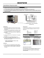
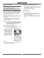
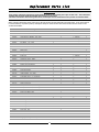
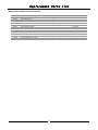
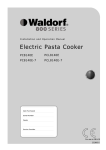
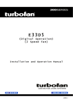
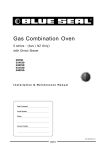
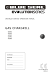
220MSERIES
E20M Series
(Manual Operation)
Installation and Operation Manual
234090-1
MANUFACTURED BY
Moffat Limited
Christchurch
New Zealand
INTERNATIONAL CONTACTS
AUSTRALIA
Moffat Pty Limited
E.Mail:
Main Office:
Service:
Spares:
Customer Service:
[email protected]
(tel) (03) 9518 3888
(fax) (03 9518 3833
(tel): 1800 622 216
(tel): 1800 337 963
(tel): 1800 335 315
(fax): 1800 350 281
CANADA
Serve Canada
Web:
E.Mail:
Sales:
Service:
www.servecanada.com
[email protected]
(tel): 800 551 8795 (Toll Free)
(tel): 800 263 1455 (Toll Free)
NEW ZEALAND
Moffat Limited
Web:
E.Mail:
Main Office:
www.moffat.co.nz
[email protected]
(tel): 0800 663328
UNITED KINGDOM
Blue Seal
Web:
E.Mail:
Sales:
Spares:
Service:
www.blue-seal.co.uk
[email protected]
(tel): 0121 327 5575
(fax): 0121 327 9711
(tel): 0121 322 6640
(fax): 0121 327 9201
(tel): 0121 322 6644
(fax): 0121 327 6257
UNITED STATES
Moffat
Web:
Sales:
Service:
www.moffat.com
(tel): 800 551 8795 (Toll Free)
(tel): 336 661 1556
(fax): 336 661 9546
(tel): 800 858 4477 (Toll Free)
(tel): 366 661 1556
(fax): 336 661 1660
REST OF WORLD
Moffat Limited
Web:
E.Mail:
www.moffat.co.nz
[email protected]
The reproduction or copying of any part of this manual by any means whatsoever is strictly forbidden unless authorized previously in writing
by the manufacturer.
In line with policy to continually develop and improve its products, Moffat Ltd. reserves the right to change the specifications and design
without prior notice.
© Copyright Moffat Ltd. June 2010.
Contents List
E20M Series Turbofan Convection Ovens.
Model Numbers Covered in this Manual
E22M3 - Turbofan Oven - 3 Tray Convection Oven.
E23M3 - Turbofan Oven - 3 Tray Convection Oven.
E27M2 - Turbofan Oven - 2 Tray Convection Oven.
E27M3 - Turbofan Oven - 3 Tray Convection Oven.
E28M4 - Turbofan Oven - 4 Tray Convection Oven.
Introduction ........................................................................................................... 2
Safety Information
Specifications ......................................................................................................... 3
Installation............................................................................................................. 4
Installation Requirements
Unpacking
Location
Clearances
Stand Mounted Ovens
Electrical Connection
Positioning and Levelling of Oven
Initial Start-Up
Operation ............................................................................................................... 6
Operation Guide
Oven Control Panel
Description of Controls
Using the Oven
Cleaning ................................................................................................................. 7
Cleaning Guidelines
Oven Cleaning
Fault Finding ........................................................................................................ 10
Electrical Schematics ........................................................................................... 11
Replacement Parts List ........................................................................................ 13
Introduction
Before using your new oven, please read this instruction
manual carefully, pay particular attention to any information
labelled ‘WARNING’, ‘CAUTION’, ‘IMPORTANT’ or
‘NOTE’ in this manual.
Warning
Indicates a hazardous situation
which, if not avoided, will result in
death or serious injury.
Caution
Indicates a hazardous situation
which, if not avoided, will result in
minor or moderate injury.
This manual must be kept by the owner for future
reference.
A record of the Date of Purchase, Date of Installation
and Serial Number of the oven should be recorded in
the area provided below.
The serial number of this oven can be found on the
Technical Data Plate located on the front right hand
side panel, see diagram in ‘Installation Section’.
Model Number:
Serial Number:
If you are unsure of any aspect of the installation,
instructions or performance of your oven, contact your
TURBOFAN dealer promptly. In many cases a phone call
could answer your question.
Dealer:
Service Provider:
Should you contact your TURBOFAN dealer on any matter
concerning this oven, please have the information provided
opposite, readily available.
Date Purchased:
Date Installed:
Safety Information
For your safety, please pay attention to the following symbols
marked on the appliance.
- Risk of electric shock.
No user serviceable parts inside.
Qualified service person access only.
Disconnect from power before servicing.
2
Specifications
E22M3
E23M3
E27M2 / E27M3
E28M4
Oven Tray Details
Oven Power Ratings
E22M3
E23M3
E27M2
E27M3
E28M4
110-120V,
1P+N+E, 60HZ, 1.5 kW
220-240V,
1P+N+E, 50/60HZ, 2.0 kW
208V,
1P+N+E, 50-60 HZ, 2.7 kW
220V,
1P+N+E, 50-60 HZ, 3.0 kW
230-240V,
1P+N+E, 50-60 HZ, 3.0 kW
208V,
1P+N+E, 50-60HZ, 2.7kW
220V,
1P+N+E, 50-60HZ, 3.0kW
230-240V,
1P+N+E, 50-60HZ, 3.0kW
208V,
1P+N+E, 50-60HZ, 4.2kW
220V,
1P+N+E, 50-60HZ, 4.7kW
230-240V,
1P+N+E, 50-60HZ, 4.7kW
208V,
1P+N+E, 50-60HZ, 5.4kW
220V,
1P+N+E, 50-60HZ, 6.0kW
230-240V,
1P+N+E, 50-60HZ, 6.0kW
Tray Capacity
3
2
Tray Spacing
E22M3
3 x EN /3 Tray
3 x US ½ Pan
70 mm / 2 3/4”
E23M3
3 x EN 2/3 Tray
3 x US ½ Pan
85 mm / 3 1/3”
E27M2
3 x EN 600 x 400 mm Tray
3 x US Full Pan
85 mm / 3 1/3”
E27M3
3 x EN 600 x 400 mm Tray
3 x US Full Pan
85 mm / 3 1/3”
E28M4
4 x EN 600 x 400 mm Tray
4 x US Full Pan
76 mm / 3 ”
Installation
Installation Requirements
Important:
•
Installation shall comply with local electrical, health and safety requirements.
•
It is most important that this oven is installed correctly and that oven operation is correct before use.
•
If you have any questions regarding the proper installation and / or operation of this oven, please contact your local
Turbofan distributor.
Electrical Power
Rating
Oven
Serial Number
Oven
Model Number
Current Draw
MOFFAT LIMITED
CHRISTCHURCH ( NEW ZEALAND )
MODEL
CODE
SERIAL
LOT
12.0 A @ 115 V a.c.
1P+N+E 110-120 V a.c.
E22M3
USE22M3
xxxxxx
yywwxxx
*******
50-60 Hz
1.5 kW
THIS APPLIANCE MUST BE EARTHED / GROUNDED
THIS APPLIANCE SHALL BE INSTALLED IN ACCORDANCE WITH CURRENT
REGULATIONS AND USED ONLY IN A WELL-VENTILATED SPACE. REFER TO THE
INSTRUCTIONS BEFORE INSTALLING AND USING THIS APPLIANCE.
Technical Data Plate - Data and Location
(example only)
Unpacking
Clearances
1. Remove all packaging and transit protection including
all protective plastic coating from the exterior stainless
steel panels.
2. Check the oven and supplied parts for damage. Report
any damage immediately to the carrier and distributor.
3. Check that the following parts have been supplied with
your oven:4 x Leg Adjustable.
To ensure correct ventilation for the motor and controls,
the following minimum installation clearances are to be
adhered to:Top
Rear
Left-hand side
Right-hand side
100 mm / 4”.
25 mm / 1”.
25 mm / 1”.
25 mm / 1”.
Important:
4. Report any deficiencies to the distributor who supplied
your oven.
5. Securely fit the 4 legs supplied with the oven.
6. Check that the available electrical supply is correct to
that shown on the Technical Data Plate located on the
front right hand side panel.
•
The vent located at the top (E22 Ovens) or rear (Other 20
Series Ovens) of the oven must NOT be obstructed.
Oven Vent Location
E22 Ovens
Oven Vent Location
E23, E27, E28 Ovens
Refer to ‘Specifications’ section, ‘Oven
Specifications Tables’.
Location
1. Position the oven in its approximate working position.
2. The unit should be positioned so that the control panel
and oven shelves are easily reachable for loading and
unloading.
Stand Mounted Oven
For ovens that are to be mounted to a stand, the oven feet
are used to level the oven on the stand. Refer to the
instructions supplied with separately ordered stands for
mounting details.
4
Installation
Electrical Connection
Positioning and Levelling of Oven
1. Correctly locate the oven into its final operating position
and using a spirit level, adjust the legs so that the oven
is level and at the correct height.
2. Adjust the oven feet to level the oven.
Warning
This oven must be earthed / grounded.
If the supply cord is damaged, it must be replaced by a
suitably qualified person in order to avoid a hazard.
Initial Start-Up
Each oven should be connected to an adequately protected
power supply and an isolation switch mounted adjacent to,
but not behind the oven and must be readily accessible to
the operator. This switch must be clearly marked and
readily accessible in case of fire.
Before using the new oven;
1. For first time use of the oven, operate the oven for
about 1 hour at 200°C / 400°F to remove any fumes or
odours which may be present.
2. Please refer to the Operation Section of this manual for
details on how to correctly operate and shutdown the
oven.
Check the electricity supply is correct to as shown on the
Technical Data Plate on the front right hand corner of the
oven side panel.
Ovens Supplied with Cordsets (E22M3, E23M3, E27M2, E27M3)
1. Ensure that the oven is fitted with the appropriate
power cord and plug.
NOTE: For non USA / Canada E27M3 Ovens only,
ovens will be supplied with a bare cord only.
An appropriate plug must be supplied and
fitted by a suitably qualified person.
Ovens Supplied without Cordsets (E28M4).
NOTE: All electrical connections must only be carried
out by a suitably qualified person.
1. Remove oven rear cover panel. Compression
Electrical
Panel
2. Bring the supply cable up
Gland
through the grommet at the
back of oven and through the
compression gland on the
electrical switchgear panel.
3. Connect the mains supply to
the appropriately marked
terminals on the terminal
Grommet
block.
NOTE:
• Fixed wiring installations must incorporate an
all-pole disconnection switch.
5
Operation
Operation Guide
•
Turbofan Ovens have been designed to provide simple operation.
•
This oven is intended for use in a commercial kitchen and must only be put to the use for which it was intended, i.e.
cooking food product. To use this oven correctly please read the following sections carefully:-
Oven Control Panel
5
3
4
2
1
Using the Oven
Description of Controls
1
Power ‘On’ Indicator Light.
Indicator light illuminates when the ‘On’ / ‘Off’ ‘Temperature’ control is turned ‘On’.
2
‘On’ - ‘Off’ and ‘Temperature Control’.
Used to turn the oven ‘On’ / ‘Off’ and to select the
oven temperature. Also turns the oven interior light
‘On’ / ‘Off’. (Not E22M3).
Caution
Some parts of this oven will become VERY
HOT during use and could cause burns if
touched accidentally.
To Turn ‘On’ the Oven;- Rotate ‘Temperature’ Control
(2) from the ‘Off’ position. ‘Power On’ Indicator light (1)
illuminates.
3
Oven Heating Indicator Light.
Indicator light illuminates when the elements are
cycling ‘On’. The oven heating indicator light will
turn ‘Off’ when the oven is up to temperature.
To Set the Temperature;- Rotate ‘Temperature ’ Control
(2) to the temperature required. ‘Oven Heating’ indicator
light (3) will remain ‘On’ until the oven is up to
temperature.
4
Timer Control (60 Minute).
Used to set the bake time. At any stage, the time
can be adjusted in either direction. For settings less
than 10 minutes, first set to a higher setting, then
turn the timer down to the time required.
To Load the Oven;- open the oven door and load
product. Avoid delays in loading the oven as this will delay
the oven’s temperature recovery.
5
To Set the Timer;- Rotate the ‘Timer Control’ (4) to the
required time.
Time Up Indicator Light.
Indicator light illuminates and the oven buzzer will
sound when baking is complete.
NOTE: This oven can be used without using the
‘Timer Control’, as it is purely a timer and does
not control the baking operation of the oven.
Time Up;- When the timer reaches 0 minutes the buzzer
sounds and the ‘Time Up’ indicator light (5) illuminates.
To cancel buzzer, turn Timer Control (4) to the ‘Off’
position.
To Turn ‘Off’ the Oven;- Rotate ‘Temperature’ Control
(2) to ‘Off’ position. ‘Power On’ light (1) will turn ‘Off’.
6
Cleaning
Cleaning Guidelines
c. Pull racks forward to disengage the location pins at
the rear of rack from the fan baffle, remove the side
racks from the oven.
Caution
Always turn off electrical power at the
mains supply before commencing cleaning.
Side Rack
Rear
Location
Pins
This oven is not water proof.
Do not use
water jet spray to clean interior or exterior
of the appliance.
To achieve the best results, cleaning must be regular and
thorough. If any small faults occur, have them looked at
promptly. Don't wait until they cause a complete
breakdown.
d. Clean all racks with a mild anti bacterial detergent
and hot water, using a soft bristled brush.
NOTE:
e. Dry the racks thoroughly with a dry cloth.
f. To refit the racks, engage the locating pins at the
rear of side rack into the locating holes in the fan
baffle at the rear of the oven.
• Carefully read and follow the safety instructions on
the label of the cleaning product to be used.
• DO NOT use harsh abrasive scouring pads or
g. At the same time locate the front of the rack over
the rack / baffle securing screw and hand tighten
the rack / baffle securing screw.
abrasive detergents as they could damage the oven.
• Ensure that any detergent or cleaning material has
been completely removed after each cleaning.
h. Refit the wire oven racks to the oven.
To keep your oven clean and operating at peak efficiency,
follow the procedures shown below:-
Fan Baffle (Not E22M3)
a. Remove side racks as shown previously.
Oven Cleaning
b. Undo (anti-clockwise) and remove the rack / baffle
securing screw at the top of the fan baffle. (E27 /
E28 Ovens, have 2 rack / baffle securing screws).
NOTE:
• If the oven usage is very high, the cleaning
procedure should be carried out on a more frequent
basis.
Securing Screw
• Allow the oven interior to cool to approx 50˚C /
120˚F before commencing cleaning.
Stainless Steel Surfaces
a. Thoroughly clean the exterior surfaces of the oven
with a damp cloth moistened with a mild detergent
solution or a soft bristled brush.
Location
Brackets
b. Baked on deposits or discolouration may require a
good quality stainless steel cleaner. Always apply
cleaner when the oven is cold and rub in the
direction of the grain.
c. Tilt the fan baffle forward and lift up off the location
brackets at rear of oven.
d. Clean the fan baffle with mild anti bacterial
detergent and a hot water solution using a soft
bristled brush.
Side Racks
a. Remove the wire oven racks.
e. Dry fan baffle thoroughly with a soft dry cloth
before re-fitting.
b. Partially undo the rack / baffle securing screw (anticlockwise) securing the rack to oven wall, until the
rack is loose.
f. Refit the fan baffle and hand tighten the rack /
baffle securing screw(s) to secure the fan baffle.
Fan Baffle
Securing Screw
Add Image of location
of Rack Thumbscrew
with rack in place.
7
Cleaning
Lamp Glass (Not E22M3)
a. With side racks and fan baffle removed, unscrew
lamp glass, anti-clockwise.
Oven Interior
• Allow the oven interior to cool to approx 50˚C /
120˚F before commencing cleaning.
a. Remove the oven racks and the fan baffle as shown
previously.
b. Clean any build up of grease from the oven interior,
using a mild anti bacterial detergent, a hot water
solution and a soft bristled brush.
c. Dry the oven thoroughly with a soft dry cloth.
Unscrew AntiClockwise
d. Clean the oven regularly with a good quality oven
cleaner.
Door Glass Cleaning
b. Clean the lamp glass using a soft cloth with a mild
anti bacterial detergent and a hot water solution.
• Ensure that the oven door is cool before cleaning
c. Dry the lamp glass thoroughly with a dry cloth.
the door glass.
d. To refit the lamp glass, screw the glass in clockwise.
Do not over tighten the lamp glass.
a. Open the oven door.
NOTE: Maintain a hold of the door with one hand
whilst cleaning the inner glass, to prevent the
door from closing.
Door Seal
a. To remove door seal, pull the 1 piece seal forward
until it pulls out of the location groove around the
oven. Note the way the seal is fitted to the
oven, with the lip facing inwards.
b. Whilst holding the oven door in the open position,
grasp the bottom of the inner glass and pull glass
towards you until the top of the inner glass rises up.
Pull Seal out of
locating channel
b. Check for wear and damage to the door seal and
replace as required.
c. Wash the door seal in a sink, taking care not to cut
or damage the seal.
d. Dry the door seal thoroughly.
e. Refit door seal with lip facing into centre of the
oven.
Refit Seal with Lip
facing inwards
c. Grasp the inner glass by the finger tabs at the top
of the glass and raise the inner glass to the vertical
position.
f. Press the door seal into the locating groove in the
front face of the oven until the seal is properly
located all around the oven.
Finger Tabs
8
Cleaning
d. Whilst still holding the oven door in the open
position, clean the inner glass and the inside of the
outer glass with a conventional glass cleaner.
d. Grasp the inner glass firmly on either side and pull
upwards to remove the inner glass from the locating
pegs on either side of the door.
Inner Glass
e. Dry the oven glass thoroughly with a soft dry cloth.
f. On completion of door glass cleaning, lower the
inner glass back into the door, the glass will locate
itself in the correct position.
Door Inner Glass Re-Fitting
a. To refit the inner glass, locate the 2 locating tabs on
either side of the inner glass into the 2 pegs on the
door and push down on the inner glass until it locks
firmly into position.
g. Close the oven door.
Door Inner Glass Removal
It is possible to remove the inner glass completely from
the oven door for heavy cleaning. This can be done as
follows:a. Open the oven door fully.
Locating Tab
b. Using a suitable instrument, move the door lock
catches from the unlocked to the locked position to
prevent the door from closing.
Locating Peg
b. Lower the inner glass back into the door, the glass
will locate itself in the correct position.
Door Lock Catch in
Unlocked Position
c. Open the oven door fully and using a suitable
instrument, move the door lock catches to the
unlocked position.
Door Lock Catch in
Unlocked Position
Door Lock Catch in
Locked Position
NOTE: Check that both Door Lock Catches are in the
‘Un-Locked’ position before closing the door.
d. Close the oven door.
c. Raise the door until it is restrained by the door lock
catches.
9
Fault Finding
You may encounter a problem not covered in this section,
please contact your service provider who will require the
following information:-
This section provides a reference to the more common
problems that may occur during the operation of your
oven. This fault finding guide is intended to help you
correct and accurately diagnose problems with your oven.
• The Model and Serial Number of the oven, can be
When fault finding a problem, always use a process of
elimination starting with the simplest solution and working
through to the most complex. Never overlook the obvious.
Fault
found on the Technical Data Plate located on the
front right hand side panel of the oven.
Possible Causes
Remedy
Mains isolating switch, circuit breaker or
fuses are 'Off' at the power board.
Turn 'On'.
Door not closed fully.
Close door. (Refer ‘Door does not close fully’).
The external power switch is ‘On’, the oven Turn ‘On’ the ‘On-Off Temp Control’ switch.
is 'Off'. (Not E22).
(‘Power On’ light will illuminate when oven is
‘On’) (Not E22).
Oven does not operate / No heat in oven.
Oven heats up but fan does not operate.
Door does not close fully.
Oven Door hot to touch
Overtemp tripped (No lights, no power
light).
Reset Overtemp.
Overtemp faulty.
Call for service.
Element faulty.
Call for service.
Thermostat faulty.
Call for service.
Door Switch faulty.
Call for service.
On / Off Switch faulty.
Call for service.
Heating Relay faulty (Not E22M3).
Motor timer faulty (Not E22M3).
Call for service.
Call for service.
Fan motor faulty.
Call for service.
Fan or fan motor obstructed.
Call for service.
Tray in way of door.
Correctly position tray on rack.
Door Latches in ‘Locked’ position.
Check position of door latches and ‘Unlock’.
Door glass not fitted correctly.
Refit door glass.
Door not fitted correctly.
Refit door.
Door seal obstruction.
Correctly install door seal. (Refer to the
‘Cleaning and Maintenance’ Section).
Inner glass not fitted.
Fit inner door glass.
Bake timer not set correctly.
For settings less than 10 minutes, first set timer
to a higher setting then turn back to setting
required.
Bake timer faulty.
Call for service.
Blown bulb.
Replace bulb.
Too high a temperature selected.
Select a lower temperature.
Oven or racks not level.
Check oven racks and level.
Insufficient air space around trays or
baking tins.
Ensure oven racks are spaced to allow air flow
around baking on all shelves.
Oven overloaded with too much product.
Re-load oven.
Opening oven door un-necessarily.
Ensure oven door remains closed during the
baking process.
Oven door seal damaged or faulty.
Check seals and replace if damaged.
Oven vent restricted.
Ensure oven vent not blocked or shrouded.
Faulty thermostat.
Call for service.
Bake timer does not time down.
Oven light not illuminating (Not E22M3).
Uneven cooking.
10
Electrical Schematics
110-120V, 60Hz.
220-240V 50/60Hz.
Electrical Schematic E22M3 Turbofan Oven
208V, 50-60Hz.
220V, 50-60Hz.
230-240V, 50-60Hz.
Electrical Schematic E23M3 Turbofan Oven
11
Electrical Schematics
Electrical Schematic E27M2 Turbofan Oven
208V, 50-60Hz.
220V, 50-60Hz.
230-240V, 50-60Hz.
Electrical Schematic E27M3 Turbofan Oven
208V, 50-60Hz.
220V, 50-60Hz.
230-240V, 50-60Hz.
Electrical Schematic E28M4 Turbofan Oven
208V, 50-60Hz.
220V, 50-60Hz.
230-240V, 50-60Hz.
12
Replacement Parts List
Important:
Only genuine authorized replacement parts should be used for the servicing and repair of this oven. The instructions
supplied with the parts should be followed when replacing components.
For further information and servicing instructions, contact your nearest authorized service provider or Turbofan Dealer.
When ordering replacement parts, please quote the part number and the description as listed below. If the part required
is not listed below, request the part by description and quote model number and serial number which is shown on the
Technical Data Plate.
Item
Description
E22
E23
E27M2 / E27M3
232765
Oven Element, 1500W, 110 - 120V
232766
Oven Element, 2000W, 230 - 240V
234088
Oven Element, 2800W, 230 - 240V
M2 only
234089
Oven Element, 2800W, 208 - 220V
M2 only
234107
Oven Element, 4500W, 208 - 220V
M3 only
234108
Oven Element, 4500W, 230 - 240V
M3 only
025387
Fan Motor, 110 - 120V
013431K
Fan Motor, 50 / 60Hz, 208 - 240V
234139
024503
024562
024505
Fan Motor, 50 - 60Hz, 208 - 240V
Motor Timer, 230V
Relay, 25A
Relay, 30A
234802
234803
Fuse Holder
Fuse 10A
025400
233573
233607
Overtemp, 360°C - 680°F
Overtemp Cap
Thermostat, 50 - 260°C / 150 - 500°F
233887
233616
233617
233862
234251
234136
011760
233613
015822
011794
Rotary ON / OFF Switch
Knob Thermostat, 50 - 260°C
Knob Thermostat, 150 - 500°F
Door Microswitch
Capacitor 5uF
LED Indicator, 110 - 250V
Bake Timer 60 Minute
Knob Bake Timer (0 - 60 Minute)
Buzzer, 110 - 120V
Buzzer, 208 - 240V
233115
233884
231814
Oven Lamp Lens
Lamp Bulb G9 25W, 120V Halogen
Lamp Bulb G9 25W, 230V Halogen
233370
Door Inner Glass - E22
233913
Door Inner Glass - E23
233368
Door Inner Glass - E27
233346
234602
Door Inner Glass - E28
Door Inner Glass Catch
233292
Door Hinge - E22
233293
Door Hinge - E23
233294
Door Hinge - E27
233295
234465
232667
232666
234466
Door Hinge - E28
Door Seal - E22
Door Seal - E23
Door Seal - E27M2 / E27M3
Door Seal E28
232379
Leg Adjustable (73 - 80 mm)
M3 only
M3 only
13
E28
Replacement Parts List
Replacement Parts List (Continued).
Item
Description
E22
E23
E27M2 / M3
233521
Side Rack LH, E22
233522
Side Rack RH, E22
232682
Side Rack LH, E23
232683
Side Rack RH, E23
233558
Side Rack LH, E27M3
M3 only
233559
234721
234722
233556
233564
Side Rack RH, E27M3
Side Rack LH, E27M2
Side Rack RH, E27M2
Side Rack, E28
Oven Rack E22, E23
M3 only
M2 only
M2 only
233565
Oven Rack E27, E28
233552
Rack / Baffle Securing Screw
14
E28