1
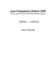
Model ZC4001 User Guide
Audio Client
ZC4001U DFU_00_cover
Page 5
06.3.30, 9:09 AM
Adobe PageMaker 6.5J/PPC
IMPORTANT SAFETY
INSTRUCTIONS
CAUTION
RISK OF ELECTRIC SHOCK
DO NOT OPEN
CAUTION: TO REDUCE THE RISK OF ELECTRIC SHOCK,
DO NOT REMOVE COVER (OR BACK)
NO USER-SERVICEABLE PARTS INSIDE
REFER SERVICING TO QUALIFIED SERVICE PERSONNEL
The lightning flash with arrowhead symbol within an equilateral triangle is
intended to alert the user to the presence of uninsulated “dangerous voltage”
within the product’s enclosure that may be of sufficient magnitude to constitute
a risk of electric shock to persons.
The exclamation point within an equilateral triangle is intended to alert the user
to the presence of important operating and maintenance (servicing) instructions
in the literature accompanying the product.
READ BEFORE OPERATING EQUIPMENT
This product was designed and manufactured to
meet strict quality and safety standards. There are,
however, some installation and operation
precautions which you should be particularly
aware of.
1.
Read Instructions – All the safety and
operating instructions should be read before
the product is operated.
2.
Retain Instructions – The safety and operating
instructions should be retained for future
reference.
3.
Heed Warnings – All warnings on the product
and in the operating instructions should be
adhered to.
WARNING
4.
TO REDUCE THE RISK OF FIRE OR ELECTRIC SHOCK,
DO NOT EXPOSE THIS APPLIANCE TO RAIN OR MOISTURE.
Follow Instructions – All operating and use
instructions should be followed.
5.
Cleaning – Unplug this product from the wall
outlet before cleaning. Do not use liquid
cleaners or aerosol cleaners. Use a damp
cloth for cleaning.
6.
Attachments – Do not use attachments not
recommended by the product manufacturer
as they may cause hazards.
7.
Water and Moisture – Do not use this product
near water-for example, near a bath tub, wash
bowl, kitchen sink, or laundry tub, in a wet
basement, or near a swimming pool, and the
like.
8.
Accessories – Do not place this product on an
unstable cart, stand, tripod, bracket, or table.
The product may fall, causing serious injury to
a child or adult, and serious damage to the
product. Use only with a cart, stand, tripod,
bracket, or table recommended by the
manufacturer, or sold with the product. Any
mounting of the product should follow the
manufacturer’s instructions, and should use a
mounting accessory recommended by the
manufacturer.
CAUTION: TO PREVENT ELECTRIC SHOCK, MATCH WIDE BLADE OF PLUG
TO WIDE SLOT, FULLY INSERT.
ATTENTION: POUR ÉVITER LES CHOCS ÉLECTRIQUES, INTRODUIRE LA
LAME LA PLUS LARGE DE LA FICHE DANS LA BORNE CORRESPONDANTE
DE LA PRISE ET POUSSER JUSQU’AU FOND.
NOTE TO CATV SYSTEM INSTALLER:
This reminder is provided to call the CATV (Cable-TV) system installer’s attention to Section 820-40 of the
NEC which provides guidelines for proper grounding and, in particular, specifies that the cable ground
shall be connected to the grounding system of the building, as close to the point of cable entry as practical.
NOTE:
This equipment has been tested and found to
comply with the limits for a Class B digital device,
pursuant to Part 15 of the FCC Rules. These limits
are designed to provide reasonable protection
against harmful interference in a residential
installation. This equipment generates, uses and
can radiate radio frequency energy and, if not
installed and used in accordance with the
instructions, may cause harmful interference to
radio communications. However, there is no
guarantee that interference will not occur in a
particular installation. If this equipment does cause
harmful interference to radio or television
reception, which can be determined by tuning the
equipment off and on, the user is encouraged to try
to correct the interference by one or more of the
following measures:
ZC4001U DFU_00_cover
Page 2
- Reorient or relocate the receiving antenna.
- Increase the separation between the equipment
and receiver.
- Connect the equipment into an outlet on a circuit
different from that to which the receiver is
connected.
- Consult the dealer or an experienced radio/TV
technician for help.
NOTE:
Changes or modifications not expressly approved
by the party responsible for compliance could void
the user’s authority to operate the equipment.
06.3.30, 9:09 AM
9.
A product and cart combination should be
moved with care. Quick stops, excessive
force, and uneven surfaces may cause the
product and cart combination to overturn.
10.
Ventilation – Slots and openings in the cabinet
are provided for ventilation and to ensure
reliable operation of the product and to protect
it from overheating, and these openings must
not be blocked or covered. The openings
should never be blocked by placing the
product on a bed, sofa, rug, or other similar
surface. This product should not be placed in
a built-in installation such as a bookcase or
rack unless proper ventilation is provided or
the manufacturer’s instructions have been
adhered to.
11.
Power Sources – This product should be
operated only from the type of power source
indicated on the marking label. If you are not
sure of the type of power supply to your home,
consult your product dealer or local power
company. For products intended to operate
from battery power, or other sources, refer to
the operating instructions.
Adobe PageMaker 6.5J/PPC
12.
Grounding or Polarization – This product may
be equipped with a polarized alternatingcurrent line plug (a plug having one blade
wider than the other). This plug will fit into the
power outlet only one way. This is a safety
feature. If you are unable to insert the plug
fully into the outlet, try reversing the plug. If the
plug should still fail to fit, contact your
electrician to replace your obsolete outlet. Do
not defeat the safety purpose of the polarized
plug.
16.
Lightning – For added protection for this
product during a lightning storm, or when it is
left unattended and unused for long periods of
time, unplug it from the wall outlet and
disconnect the antenna or cable system. This
will prevent damage to the product due to
lightning and power-line surges.
17.
Power Lines – An outside antenna system
should not be located in the vicinity of
overhead power lines or other electric light or
power circuits, or where it can fall into such
power lines or circuits. When installing an
outside antenna system, extreme care should
be taken to keep from touching such power
lines or circuits as contact with them might be
fatal.
AC POLARIZED PLUG
13.
14.
15.
Power-Cord Protection – Power-supply cords
should be routed so that they are not likely to
be walked on or pinched by items placed upon
or against them, paying particular attention to
cords at plugs, convenience receptacles, and
the point where they exit from the product.
Protective Attachment Plug – The product is
equipped with an attachment plug having
overload protection. This is a safety feature.
See Instruction Manual for replacement or
resetting of protective device. If replacement
of the plug is required, be sure the service
technician has used a replacement plug
specified by the manufacturer that has the
same overload protection as the original plug.
Outdoor Antenna Grounding – If an outside
antenna or cable system is connected to the
product, be sure the antenna or cable system
is grounded so as to provide some protection
against voltage surges and built-up static
charges. Article 810 of the National Electrical
Code, ANSI/NFPA 70, provides information
with regard to proper grounding of the mast
and supporting structure, grounding of the
lead-in wire to an antenna discharge unit, size
of grounding conductors, location of antennadischarge unit, connection to grounding
electrodes, and requirements for the
grounding electrode. See Figure 1.
18.
Overloading – Do not overload wall outlets,
extension cords, or integral convenience
receptacles as this can result in a risk of fire or
electric shock.
19.
Object and Liquid Entry – Never push objects
of any kind into this product through openings
as they may touch dangerous voltage points
or short-out parts that could result in a fire or
electric shock. Never spill liquid of any kind on
the product.
20.
Servicing – Do not attempt to service this
product yourself as opening or removing
covers may expose you to dangerous voltage
or other hazards. Refer all servicing to
qualified service personnel.
21.
Damage Requiring Service – Unplug this
product from the wall outlet and refer servicing
to qualified service personnel under the
following conditions:
a.
When the power-supply cord or plug is
damaged.
b.
If liquid has been spilled, or objects have
fallen into the product.
c.
If the product has been exposed to rain or
water.
d.
If the product does not operate normally by
following the operating instructions. Adjust
only those controls that are covered by the
operating instructions as an improper
adjustment of other controls may result in
damage and will often require extensive work
by a qualified technician to restore the product
to its normal operation.
e.
If the product has been dropped or damaged
in any way, and
f.
When the product exhibits a distinct change in
performance – this indicates a need for
service.
Page 3
Replacement Parts – When replacement
parts are required, be sure the service
technician has used replacement parts
specified by the manufacturer or have the
same characteristics as the original part.
Unauthorized substitutions may result in fire,
electric shock, or other hazards.
23.
Safety Check – Upon completion of any
service or repairs to this product, ask the
service technician to perform safety checks to
determine that the product is in proper
operating condition.
24.
Wall or Ceiling Mounting – The product should
be mounted to a wall or ceiling only as
recommended by the manufacturer.
25.
Heat – The product should be situated away
from heat sources such as radiators, heat
registers, stoves, or other products (including
amplifiers) that produce heat.
FIGURE 1
EXAMPLE OF ANTENNA GROUNDING AS PER
NATIONAL ELECTRICAL CODE, ANSI/NFPA 70
ANTENNA
LEAD IN WIRE
GROUND
CLAMP
ANTENNA
DISCHARGE UNIT
(NEC SECTION 810-20)
ELECTRIC
SERVICE
EQUIPMENT
GROUND CLAMPS
GROUNDING CONDUCTORS
(NEC SECTION 810-21)
POWER SERVICE GROUNDING
ELECTRODE SYSTEM
(NEC ART 250, PART H)
NEC - NATIONAL ELECTRICAL CODE
This Class B digital apparatus complies with
Canadian ICES-003.
ZC4001U DFU_00_cover
22.
06.3.30, 9:09 AM
Adobe PageMaker 6.5J/PPC
Cet appareil numérique de la Classe B est conforme
à la norme NMB-003 du Canada.
INTRODUCTION
INTRODUCTION .................................. 1
PRECAUTIONS ................................... 1
DESCRIPTION ..................................... 1
FEATURES .......................................... 2
FRONT PANEL .................................... 3
SETUP ................................................. 6
FL DISPLAY AND INDICATOR ......................................... 3
CLOCK SETTING ............................................................. 8
TOP PANEL ......................................... 3
REAR PANEL ...................................... 4
REMOTE CONTROL OPERATION ..... 4
CONNECTIONS ................................... 5
PLC SETTING ................................................................... 6
SLEEP TIMER SETTING .................................................. 7
BASS BOOST SETTING ................................................... 7
SOUND EFFECT SETTING .............................................. 7
DISPLAY DIMMER SETTING ........................................... 7
STANDBY MODE SETTING ............................................. 8
BASIC OPERATION ............................ 9
TROUBLESHOOTING ....................... 10
TECHNICAL SPECIFICATIONS ....... 10
DIMENSIONS .................................... 10
DESCRIPTION
Thank you for purchasing the Marantz ZC4001
Audio Client.
This remarkable component has been engineered
to provide you with many years of home theater
enjoyment. Please take a few minutes to read this
manual thoroughly before you connect and
operate the ZC4001.
As there are a number of connection and
configuration options, you are encouraged to
discuss your own particular home theater setup
with your Marantz A/V specialist dealer.
PRECAUTIONS
ENGLISH
TABLE OF CONTENTS
SRS WOW Audio Effect creates a panoramic
stereo audio image by producing deep and rich
bass tones and clear treble tones, enabling you to
enjoy powerful sound.
WOW, SRS and
symbol are trademarks of
SRS Labs, Inc.
WOW technology is incorporated under license
from SRS Labs, Inc.
CAUTIONS ON INSTALLATION
For heat dispersal, leave at least 20 cm/8 inch of
space between the top, back and sides of this unit
and the wall or other components.
• Do not obstruct the ventilation holes.
0.2 m (8 ins.)
0.2 m
(8 ins.)
0.2 m
(8 ins.)
0.2 m (8 ins.)
1
ZC4001U DFU_01_ENG
Page 1
06.3.30, 9:10 AM
Adobe PageMaker 6.5J/PPC
ENGLISH
FEATURES
By simply plugging the power cables of the ZC4001 and ZR6001 into ordinary home electrical outlets, the ZR6001 sends audio sources over your home electrical
line for playback by the ZC4001.
PLC (POWER LINE COMMUNICATION)
The ZR6001* converts analog audio signals into noncompressed linear PCM digital signals, modulates them into high frequency signals, and sends them over
power lines.
The ZC4001 demodulates the sent signals and converts them back to analog signals.
* If the condition of the power line degenerates because of the effects of noise from other devices or for other reasons, the ZR6001 uses an audio format of
different sampling rate and data bit length.
ROOM A
ZR6001
POWER
ON/STANDBY
PHONES
SURROUND
MODE
OPEN/CLOSE
PLAY
STOP
PAUSE
DVD
PREV.
MEMORY
VIDEO
NEXT
MODE
BS
DIGITAL
F/P
TV
TUNING
FM/AM
1
RC2020MD
Home power line
ROOM B
ROOM C
ZC4001
ZC4001
2
ZC4001U DFU_01_ENG
Page 2
06.3.30, 9:10 AM
Adobe PageMaker 6.5J/PPC
TOP PANEL
ENGLISH
FRONT PANEL
q
STANDBY
1
.
POWER ON/STANDBY
z
w
q
w
SPEAKERS
INFRARED receiver window
This window receives infrared signals for the
remote control unit.
z
x
c
POWER button and STANDBY indicator
When this button pressed once, the unit turns ON
and the display illuminates. When pressed again,
the unit turns OFF and the STANDBY indicator will
be illuminated.
v
v
x
a
s
SOURCE buttons
These buttons are used to switch the source of
ZR6001.
* When the EXT. button is pressed, the source
switches to the EXT. INPUT jack on the rear
panel.
c
Cursor ( , ,
,
n
CONTROL buttons
These buttons are used when operating the PLAY,
STOP, PAUSE, and other commands of a source.
b
FL DISPLAY AND INDICATOR
b
MUTE button
Press this button to mute the output to the
speakers. Press it again to return the previous
volume level.
n
VOLUME UP(
)/DOWN(
) buttons
This button is volume control of the ZC4001.
)/ENTER buttons
These buttons are used to operate the menu
system and source units.
d
a
Function display area
f
d
Volume/ Text display area
This area displays the input source.
This area displays the volume and other text.
s
f
PLC Status display area
This area displays the PLC reception strength.
Clock display area
This area displays the time.
3
ZC4001U DFU_01_ENG
Page 3
06.3.30, 9:10 AM
Adobe PageMaker 6.5J/PPC
ENGLISH
REAR PANEL
REMOTE CONTROL OPERATION
The ZC4001 does not come with a remote controller.
However, it does have an infrared sensor that functions as a remote control signal receptor, and therefore
it can be operated with the system remote controller (RC5500SR, etc.) of other Marantz products.
Remote-controllable range
pr
Ap
SERVICE
ONLY
ox.
5m
60°
q
q
w
e
e
EXT INPUT
This is the analog audio input. The audio inputs
require RCA-type connectors.
w
AC Power cable
Connect the power outlet on the wall.
The distance between the transmitter of the remote control unit and the infrared sensor of the ZC4001
should be less than about 16.4 ft (5meters).
If the transmitter is pointed away from the infrared sensor or if there is an obstacle between them, remote
control may not be possible.
SERVICE ONLY
This is a servicing port. Do not connect anything to
it.
4
ZC4001U DFU_01_ENG
Page 4
06.3.30, 9:10 AM
Adobe PageMaker 6.5J/PPC
CONNECTING AUDIO COMPONENTS
There is one Audio EXT INPUT jack on the rear panel. You can use this jack to input analog audio signal
from CD, TAPE DECK, or other analog source component.
CONNECTING AC POWER CABLE
Connect the AC power cable of the ZC4001 to a wall electrical outlet. Also connect the AC power cable of
the ZR6001 to a wall electrical outlet.
Notes:
• The ZC4001 and ZR6001 send audio data over power lines. Therefore, if the condition of the power line
degenerates seriously because of the effects of noise from other devices or for other reasons, audio data may
not be received or may skip.
• If the distance of the power line between the ZC4001 and ZR6001 is very long, audio data may not be received
or may skip.
• At the time of purchase, all ZC4001 and ZR6001 are set to the same Group ID. If used with this same Group
ID, you risk having your music listened into by others. Therefore, set the Group ID as explained herein.
• If the following trouble is experienced, block PLC signals from other sources using a commercially available
power filter, etc.
ENGLISH
CONNECTIONS
When a ZC4001 and ZR6001 are connected over PLC, another ZR6001 cannot be added to the same power
line and connected over PLC. In this case, PLC signals are not sent.
ROOM A
ZC4001
ZR6001
ZC4001
POWER
ON/STANDBY
PHONES
SURROUND
MODE
OPEN/CLOSE
PLAY
STOP
PAUSE
DVD
PREV.
MEMORY
VIDEO
NEXT
MODE
BS
DIGITAL
F/P
TV
TUNING
FM/AM
1
ZR6001
Home power line
If a ZR6001 and ZC4001 are connected over PLC in a nearby apartment unit for example, and there is only
a short distance between your apartment and your neighbor’s, the PLC signals from your neighbor’s
apartment can travel over power lines to your place, mix with your system, and prevent audio output.
ROOM C
ROOM B
ZR6001
ZC4001
ZC4001
ZC4001
Up to four ZC4001 units may be connected to the same system at one time.
ZC4001
ZR6001
ZR6001
5
ZC4001U DFU_01_ENG
Page 5
06.3.30, 9:10 AM
Adobe PageMaker 6.5J/PPC
ENGLISH
1. 2.
PLC SETTING
RECALIBRATION
If audio is lost when the ZC4001 and ZR6001 are
connected over a PLC connection, recalibrate the
signal to the best carrier frequency.
The ZR6001 is set first.
<ZR6001>
Using the OSD menu system, set “MULTI PLC
SERVER” to “ON”.
1
1.
1.
2.
9 MU L T I
Press and hold the ENTER button for 5 sec. or
more.
2.
Press the ENTER button.
2.
3.
The below message appears when
recalibration is complete.
The below message appears when the Group ID
has been successfully set.
<ZC4001>
I D S E T T I NG : S T AR T
MA I N
1.
EX I T
PLC
MU L T I P L C S E R V E R : ON
CONN E C T I ON MOD E :
AU T O
H I GH AUD I O QUA L I T Y
H I GH R E L I AB I L I T Y
GP
Select “9. MULTI PLC” in the SETUP MAIN
MENU with the or cursor buttons, and
press the ENTER button.
Select “MULTI PLC SERVER” with the or
cursor buttons. And select “ON” with the or
cursor buttons.
<ZC4001>
ZR6001 ON SCREEN DISPLAY MENU SYSTEM
I D S E T T I NG : S T AR T
MA I N
<ZR6001>
GP-ID SETTING : **
.
PLC
MU L T I P L C S E R V E R : ON
CONN E C T I ON MOD E :
AU T O
H I GH AUD I O QUA L I T Y
H I GH R E L I AB I L I T Y
GP
To set a Group ID, connect the AC power cables of
the ZC4001 and ZR6001 to wall power outlets as
close to each other as possible.
Set the Group ID simultaneously for the ZC4001
and ZR6001.
<ZR6001>
GP-ID SETTING : SUCCEED
EX I T
Select “9. MULTI PLC” in the SETUP MAIN
MENU with the or cursor buttons, and
press the ENTER button.
Select “GP-ID SETTING” with the
or
cursor buttons.
The below message appears if the units fail to set
the Group ID.
<ZC4001>
<ZC4001>
1. 3. 2.
<ZR6001>
GP-ID SETTING : MISSING
For details, see page 24 in the ZR6001 User’s
Guide.
1
.
1.
Press and hold the ENTER button for 5 sec. or
more.
2.
Press the
Notes:
One possible reason the Group ID cannot be set is
power line noise. In that case, unplug the power
cable of the device that is generating noise, then
plug it back in and try setting the Group ID again.
button once.
6
ZC4001U DFU_01_ENG
Page 6
Simultaneously press the ENTER buttons of
the ZR6001 and ZC4001.
<ZR6001>
Using the OSD menu system, set “GP-ID
SETTING” to “START”.
ZR6001 ON SCREEN DISPLAY MENU SYSTEM
9 MU L T I
3.
SET GROUP ID
<ZC4001>
SETUP
06.3.30, 9:10 AM
Adobe PageMaker 6.5J/PPC
WAKE UP TIMER
When the set time elapses, the ZC4001
automatically goes on standby.
The sleep timer can be set to 10, 20, 30, 40, 50, 60,
70, 80 or 90 min.
The Wake Up Timer outputs an audio alarm at the
set time. The volume level of the alarm can be
user-set.
6.
1. 2. 3. 4.
1. 6. 7. 8. 5. 6. 4. 5.
1. 2. 4. 3.
.
1
.
Press the ENTER button to return to the
normal display.
When the Wake Up Timer is turned ON, a
symbol
1.
Press the ENTER button.
1.
3.
Press the ENTER button again.
Select the sleep time. Each time the
button
is pressed, the sleep time changes in the
order of
OFF → 10 → 20 → 30 → 40 → 50 → 60 → 70
→ 80 → 90 → OFF.
Each time the
button is pressed, the sleep
time changes in the order of
OFF → 90 → 80 → 70 → 60 → 50 → 40 → 30
→ 20 → 10 → OFF.
2.
Press the ENTER button again.
3.
Each time the
and
buttons are pressed,
the Wake Up Timer switches between “ON”
and “OFF”.
4.
Press the
Press the
5.
4.
1
.
appears in front of the time display.
Press the ENTER button once, then press the
button.
8.
2.
BASS BOOST SETTING
The Bass Boost feature is turned ON/OFF as
follows.
When ON, bass tones are accented. When OFF,
normal audio is produced.
1. 1. 2. 4. 3.
7.
1
Press the ENTER button again.
and
buttons to set the volume
Press the
of the alarm.
ENGLISH
SLEEP TIMER SETTING
When the set time is reached, an audio alarm
outputs. If not stopped, the alarm gradually
gets louder. To stop the alarm, press the
ENTER button.
The Wake Up Timer can be set when the
Standby Mode is set to “NORMAL”.
button to get the hour setting.
and
buttons to set the hour.
1.
Press the ENTER button once, then press the
button twice.
2.
Press the ENTER button again.
3.
Each time the
button is pressed, the Bass
Boost setting switches between ON and OFF.
ON ↔ OFF
4.
Press the ENTER button to return to the
normal display.
Press the button to get the minutes setting.
and
buttons to set the
Press the
minutes.
Press the ENTER button to return to the
normal display.
7
ZC4001U DFU_01_ENG
Page 7
06.3.30, 9:10 AM
Adobe PageMaker 6.5J/PPC
ENGLISH
SOUND EFFECT SETTING
DISPLAY DIMMER SETTING
CLOCK SETTING
STANDBY MODE SETTING
The Sound Effect mode is set as follows: Sound
dynamics increase in the order of MODE1 →
MODE 2 → MODE3.
Setting the NIGHT MODE compresses the
dynamic range .
This softens loud passages such as sudden
explosions, to help prevent disturbing others late
at night.
The brightness of the FL display can be adjusted.
The display darkens in the order of OFF →
LEVEL1 → LEVEL2 → LEVEL3.
The time is set as follows.
The ZC4001 has two Standby Modes. The
Standby Mode is set as follows.
ECONOMY: This is a low power consumption
mode. The clock is not displayed.
NORMAL: This is the normal standby mode. The
clock is displayed.
1.
3. 5. 7.
4. 6.
1. 2. 8.
1. 1. 2. 4. 3.
1. 1. 2. 4. 3.
1
.
1. 1. 2. 4. 3.
1
.
1
1
1.
.
1.
1.
Press the ENTER button again.
3.
Select a Sound Effect mode. Each time the
button is pressed, the Sound Effect mode
changes in the order of
OFF → MODE1 → MODE2 → MODE3 →
NIGHT MODE → OFF.
Each time the
button is pressed, the Sound
Effect mode changes in the order of
OFF → NIGHT MODE → MODE3 → MODE2
→ MODE1 → OFF.
WOW is activated in all three Sound Effect
modes: 1, 2 and 3.
2.
Press the ENTER button again.
3.
Select a dimmer level. Each time the
button
is pressed, the brightness of the FL display
changes in the order of
OFF → LEVEL1 → LEVEL2 → LEVEL3 →
OFF.
Each time the
button is pressed, the
brightness of the FL display changes in the
order of
OFF → LEVEL3 → LEVEL2 → LEVEL1 →
OFF.
4.
4.
Press the ENTER button to return to the
normal display.
8
ZC4001U DFU_01_ENG
Page 8
Press the ENTER button once, then press the
button five times.
Press the ENTER button once, then press the
button four times.
Press the ENTER button once, then press the
button three times.
2.
.
Press the ENTER button to return to the
normal display.
2.
Press the ENTER button again.
3.
Each time the
and
buttons are pressed,
the clock switches between the 12-hour and
24-hour display.
4.
Press the
5.
Press the
1.
Press the ENTER button once, then press the
button six times.
2.
Press the ENTER button again.
3.
Each time the
and
buttons are pressed,
the Standby Mode switches between
“ECONOMY” and “NORMAL”.
button to get the hour setting.
and
buttons to set the hour.
6.
Press the
7.
Press the
minutes.
8.
Press the ENTER button to start the clock and
return to the normal display.
When “ECONOMY” is set as the Standby
Mode, the time is not displayed when the unit
is on standby.
Also, the Wake Up Timer cannot be set in the
Economy mode.
button to get the minutes setting.
and
buttons to set the
06.3.30, 9:10 AM
4.
Adobe PageMaker 6.5J/PPC
Press the ENTER button to return to the
normal display.
ADJUSTING THE VOLUME
LISTENING OVER THE PLC
1.
TURNING THE POWER ON
1. 2.
Check the settings of the ZR6001.
Using the OSD menu system of the ZR6001, set
“MULTI PLC SERVER” to “ON”.
For details, see the ZR6001 User’s Guide.
1.
.
POWER ON/STANDBY
1.
Press the VOLUME
/
buttons to adjust
the volume.
button increases
Pressing the VOLUME
the volume.
button decreases
Pressing the VOLUME
the volume.
Volume can be adjusted in the (Min.) 01 (Max.) 79 range.
Pressing and holding the VOLUME
/
buttons increases or decreases the volume
rapidly.
Press the POWER button to turn the power
ON.
When the power turns ON, the ZC4001
resumes the same status that existed when
power was turned OFF the last time.
Press the POWER button again to set the
ZC4001 on standby.
Caution:
Power to the ZC4001 is always ON (standby
state) while the AC power cable is connected to a
wall electrical outlet.
To completely shut OFF the power, unplug the
AC power cable from the wall electrical outlet.
However, if the AC power cable is left unplugged
for an extended period of time, the clock resets
and the time must be set again.
GP
1
.
I D S E T T I NG : S T AR T
MA I N
EX I T
1.
Press the button of the desired source.
2.
Operate the source with the PLAY, STOP,
PAUSE, , ,
and
buttons.
1. LISTENING TO THE TUNER
1. 2.
3. 4.
3. LISTENING TO SOURCES CONNECTED TO EXT
INPUT
MUTE
1.
Pressing the MUTE button temporarily mutes the
sound from the speakers.
Pressing the MUTE button again cancels the mute
and restores the original volume level.
STANDBY
1
.
POWER ON/STANDBY
1
1
2.
PLC
MU L T I P L C S E R V E R : ON
CONN E C T I ON MOD E :
AU T O
H I GH AUD I O QUA L I T Y
H I GH R E L I AB I L I T Y
STANDBY
1
2.
.
9 MU L T I
2.
To listen to these sources, the ZR6001 must be
connected to the unit and set accordingly. For
details, see the ZR6001 User’s Guide.
ZR6001 ON SCREEN DISPLAY MENU SYSTEM
1
1.
2. LISTENING TO SOURCES OVER THE PLC (CD,
TAPE, CDR, DVD, TV, VCR1, DSS OR AUX1)
ENGLISH
BASIC OPERATION
.
1.
Press the TUNER button.
2.
To switch between FM and AM, press the
TUNER button again.
3.
To select a station frequency, use the
buttons.
4.
/
.
1.
Press the EXT. button.
2.
Operate the unit connected to the EXT INPUT
jack on the rear panel.
To select a preset station, use the
/
buttons. (With the ZR6001, this works only
when stations have been preset.)
9
ZC4001U DFU_01_ENG
Page 9
06.3.30, 9:10 AM
Adobe PageMaker 6.5J/PPC
ENGLISH
HOW TO RESET THE UNIT
Should the operation or display seem to be abnormal, reset the unit with the following procedure.
The ZC4001 is turned on, press and hold the MUTE and STOP buttons simultaneously for 3 seconds or
more.
TROUBLESHOOTING
In case of trouble, check the following before calling for service:
1.
Are the connections made properly?
2.
Are you operating the unit properly following the user’s guide?
3.
Are the power amplifiers and speaker working properly?
TECHNICAL SPECIFICATIONS
AUDIO SECTION
If the unit does not operate properly, check items shown in the following table.
If your trouble cannot be recovered with the remedy actions listed in the following table, malfunction of the
internal circuitry is suspected; immediately unplug the power cable and contact your dealer, nearest
Marantz authorized dealer or the Marantz Service Center in your country.
SYMPTOM
CAUSE
The ZC4001 cannot be turned The power plug is not connected.
on.
REMEDY
GENERAL
Power Output ......... 10W + 10W (JEITA, 1kHz, 6 ohms)
.... 7W + 7W (20Hz – 20kHz, THD=0.05%, 6 ohms)
EXT INPUIT Sensitivity/Impedance .. 200mV / 22k ohms
PLC SECTION
ACCESSORIES
Modulation Method ....................................... Multi carrier
Frequency Band ..................................... 2MHz – 20MHz
Connect the power plug to the outlet.
No sound even when power is Mute is on.
Cancel mute using the MUTE button.
on.
The input cable is not connected See the connection diagram and connect the
correctly. (EXT INPUT)
cables correctly.
Power Requirement .............................. AC 120 V 60 Hz
Power Consumption ................................................ 0.3 A
Weight ..................................................... 6.6 lbs (3.0 kg)
User Guide .................................................................... 1
Specifications subject to change without prior notice.
DIMENSIONS
The volume control is turned all the way Adjust the volume.
down.
Correctly set the PLC as explained in “PLC
SETTING” on page 6. You can check whether or not
the ZC4001 is securely connected to the ZR6001
via the PLC status display area of the ZC4001.
The source (Marantz product) is not Marantz products connect over an RC-5 bus.
Correctly connect the source as explained in the
correctly connected to the ZR6001.
ZR6001 User’s Guide.
SERVICE
ONLY
The source (other brand product) is not Other brand sources are controlled by remote
control signals sent from an emitter connected to
correctly connected to the ZR6001.
the IR EMITTER OUT terminals of the ZR6001 to
the IR sensor of the source unit.
Operation requires you to set the brand code or use
the IR code learning feature. Correctly connect the
source as explained in the ZR6001 User’s Guide.
4-3/8 ins.(111.5 mm)
Nothing is heard over PLC The PLC is wrongly set.
connection.
STANDBY
1
.
POWER ON/STANDBY
Another device is generating a high Turn OFF the device that is causing the noise or
level of noise on the power line.
move it farther away from the ZC4001 and ZR6001.
Two ZR6001 units are connected to the Using the OSD menu system, set “MULTI PLC
same system.
SERVER” of one of the ZR6001 unit to “OFF”. (See
page 6)
Control with the remote control Batteries are exhausted.
Replace all the batteries with new ones.
unit fails.
Function key setting for the remote Press the AMP button on the remote control unit to
control unit is wrong.
confirm control of the ZR6001.
14-1/4 ins.(362 mm)
5-1/16 ins.(128 mm)
1/16 ins.
(1 mm)
1/16 ins.
(1 mm)
The distance between the ZC4001 and Move closer to the ZC4001.
the remote control unit is too far.
Something is blocking the ZC4001 and Remove the offending object.
the remote control unit.
14-3/16 ins.(360 mm)
10
ZC4001U DFU_01_ENG
Page 10
4-6/8 ins.(120 mm)
06.3.30, 9:10 AM
Adobe PageMaker 6.5J/PPC
www.marantz.com
You can find your nearest authorized distributor or dealer on our website.
U.S.A.
Marantz America, Inc.
1100 Maplewood Drive, Itasca, IL 60143, U.S.A.
EUROPE
Marantz Europe B.V.
P.O. Box 8744, 5605 LS Eindhoven, The Netherlands
Manufactured under license from Dolby Laboratories. “Dolby”, “Pro Logic” and the double-D symbol are trademarks of Dolby Laboratories.
Confidential Unpublished Works. Copyright 1992-1999 Dolby Laboratories, Inc. All rights reserved.
is a registered trademark.
Printed in China
ZC4001U DFU_00_cover
03/2006
Page 4
06.3.30, 9:09 AM
Adobe PageMaker 6.5J/PPC
00M10CW851250
mzh-d