1
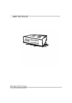
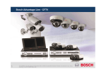
Digital Video Recorder
DVR-400
User’s manual
1
Copyright
Copyright (C) 2004 PLANET Technology Corp. All rights reserved.
The products and programs described in this User’s Manual are licensed products of PLANET Technology, This User’s
Manual contains proprietary information protected by copyright, and this User’s Manual and all accompanying hardware,
software, and documentation are copyrighted.
No part of this User’s Manual may be copied, photocopied, reproduced, translated, or reduced to any electronic medium
or machine-readable form by any means by electronic or mechanical. Including photocopying, recording, or information
storage and retrieval systems, for any purpose other than the purchaser's personal use, and without the prior express
written permission of PLANET Technology.
Disclaimer
PLANET Technology does not warrant that the hardware will work properly in all environments and applications, and
makes no warranty and representation, either implied or expressed, with respect to the quality, performance,
merchantability, or fitness for a particular purpose.
PLANET has made every effort to ensure that this User’s Manual is accurate; PLANET disclaims liability for any
inaccuracies or omissions that may have occurred.
Information in this User’s Manual is subject to change without notice and does not represent a commitment on the part of
PLANET. PLANET assumes no responsibility for any inaccuracies that may be contained in this User’s Manual. PLANET
makes no commitment to update or keep current the information in this User’s Manual, and reserves the right to make
improvements to this User’s Manual and/or to the products described in this User’s Manual, at any time without notice.
If you find information in this manual that is incorrect, misleading, or incomplete, we would appreciate your comments and
suggestions.
Regulatory
FCC Certification
This equipment has been tested and found to comply with the limits for a class A digital device, pursuant to
Part 15 of the FCC rules. These limits are designed to provide reasonable protection against harmful
interference when the equipment is operated in a commercial environment. This equipment generates, uses,
and can radiate radio frequency energy and, if not installed and used in accordance with the instruction
manual, may cause harmful interference to radio communications. Operation of this equipment in a residential
area is likely to cause harmful interference in which case the user will be required to correct the interference a
the own expense.
CE Mark
This product is marked with the CE symbol and indicates compliance with all applicable directives.
Trademarks
The PLANET logo is a trademark of PLANET Technology. This documentation may refer to numerous hardware and
software products by their trade names. In most, if not all cases, their respective companies claim these designations as
trademarks or registered trademarks.
2
Revision
User’s Manual for PLANET Digital Video Recorder
Model: DVR-400
Rev: 1.0 (Oct. 2004)
Part No. EM-DVR400V1
3
Table of Contents
Chapter 1 Introduction ..................................................................................1
Overview ...................................................................................................................... 1
DVR Functions...................................................................................................... 1
Package Content ......................................................................................................... 2
Physical Details ........................................................................................................... 2
Buttons Definitions ................................................................................................ 2
Physical Interfaces ................................................................................................ 4
Chapter 2 Preparations & Installation ..........................................................5
Installing and Configuring DVR-400 .......................................................................... 5
On-Screen Display ...................................................................................................... 9
Administration Interface ........................................................................................... 10
OSD (On Screen Display) administration............................................................ 10
Chapter 3 DVR- 400 Menu Setup ................................................................12
Introduction ............................................................................................................... 12
MAIN MENU........................................................................................................ 12
CAMERA SELECT .............................................................................................. 13
RECORD SELECT.............................................................................................. 14
VIDEO RECORDING MODE .............................................................................. 14
RECORD FRAMRATE ........................................................................................ 15
VIDEO QUALITY................................................................................................. 16
RECORD SCHEDULE ........................................................................................ 17
SUB MENU ......................................................................................................... 18
PASSWORD CHANGE .....................................................................................18
TIME SET ......................................................................................................19
DATE DISPLAY FORMAT ..................................................................................19
HDD SETUP ....................................................................................................... 20
SENSOR SETUP ................................................................................................ 20
How to enable the Motion detection recording in DVR-400................................. 21
NETWORK SETUP............................................................................................. 22
PLAYBACK Configurations ...................................................................................... 23
CONTROL BUTTONS......................................................................................... 23
Chapter 4 DVR-400 Client Utility Administration .......................................25
DVR-400 client utility................................................................................................. 25
Procedures of DVR Client utility .......................................................................... 25
Appendix A Specifications ..........................................................................29
4
Chapter 1
Introduction
1
Overview
The DVR-400 (Digital Video Recorder) is for recording/retrieving video streams from up to 4 channels at the
same time. It adopts cutting-edge digital image compression technology to compress the analog input
channel video streams, and uses HDD to record the compressed video stream.
The following operation guide explains how to operate/manage the DVR-400, and the following installation
guide explains how to complete the first DVR-400 installation on your side.
DVR Functions
·
High quality M-JPEG compression
·
Video loop through
·
Real-time 4 concurrent cameras recording
·
MAX. 120 FPS video displaying rate
·
Motion detection / video lost buzzer
·
Matured embedded system remote monitoring and control of DVR
·
4 alarm input for various application
·
Swappable HD / Max. 250 GB HD support
·
Scheduled/event/continuous recording
1
Package Content
The contents of your product should contain the following items:
DVR-400 unit
Power adapter
Screws for swappable HDD tray
Keys for swappable HDD tray
Quick installation guide
User’s manual CD
Physical Details
Front Panel of DVR-400
Rear Panel of DVR-400
Buttons Definitions
The following are the introductions of DVR-400 front panel buttons. The definitions of the front are shown
below:
2
· MENU: press to display Operation menu option
· SELECT: press to change menu field
· ENTER: press to change the setting value or enter into a sub menu
· RECORDING: press to start recording.
· STOP (recording/playback): press stop video recording/playback
ëNote
When stopping video recording; it is required to enter the
authorization password. The default value is 111111
· FAST FORWARD: press to play the recorded stream faster.
· PLAYBACK: press to start playback
· PAUSE: press to pause the video playback
· REVERSE: press to playback backward
· CHANNEL 1: press to select video source on channel 1
· CHANNEL 2: press to select video source on channel 2
· CHANNEL 3: press to select video source on channel 3
· CHANNEL 4: press to select video source on channel 4
· ALL CHANNELS: press to select all channels display
When entering or modifying password, the button definitions are shown below:
Button definition when entering password
5
means “1”
‚
means “6”
means “2”
8
means “7”
means “3”
7
means “8”
means “4”
;
means “9”
means “5”
8
means “0”
3
Physical Interfaces
Physical conection interface of DVR-400 are shown and explained in the following descriptions.
2
7
4
1
3
5
8
6
10
9
11
1. S-Video:
2. Video output:
3. Monitor: Second Video output.
4. Video input: Connect your standard video cameras to these inputs.
5. Video loop-through: These outputs provide loop-through connections, and can be used for direct
monitoring of the connected video cameras.
6. Sensor input/alarm output: 4 sensor inputs and one alarm output.
7. NTSC/PAL switch:
8. DC-in (12Voltage): Connect the power cable here.
9. Audio input/output:
10. LAN: 10/100 Ethernet via the RJ-45 socket.
11. Power switch: This switch should only be used after shutting down the unit correctly with the help of the
Power button on the front panel.
4
Chapter 2
Preparations & Installation
2
Installing and Configuring DVR-400
STEP1:
Please power off the DVR-400 and unlock the DVR-400 swappable HDD tray
STEP2:
Remove the harddisk tray cover; connect your harddisk securely with the DC power cable and IDE
cable in the harddisk tray. Make sure the installed HDD is set to “Master” and secure the HDD
using the original HD screws or the screws in the DVR-400 accessory pack.
Place and lock the HDD tray to DVR-400. Power on the DVR-400, the
DVR-400 will now automatically detect and format the new disk(s).
5
Please be sure to finish the hard disk drive installation
before using the DVR. The Maximum HDD capacity support is
250GB.
ëNote
STEP3:
Please connect TV (monitor) to the Video output connector in the rear panel.
ëNote
DVR-400 provides one S-Video and two BNC connector for video
output.
Video Input connection (TV or monitor)
STEP4:
Please use standard analog video cameras to connect to the DVR400. The DVR-400 equipped 4
BNC connectors on the rear panel for video input.
Physical camera installation with DVR-400 is shown as below:
l
Connect the camera signal line to video input on DVR-400
l
Power on camera, and you may now check the video on the screen.
DVR-400 provides 4 x BNC connectors for video source input.
6
STEP5:
Please ensure DVR-400 is power OFF before commencing, and check the power supply status.
Use standard RJ-45 cables to connect the LAN port on DVR-400.
Connect the supplied Power Adapter and power on machine.
The PWR LED Indicator should be Green during normal operation
After powering on the DVR-400, it will check HDD for several seconds; the information will be
displayed on the monitor:
HDD Checking…
HDD Checking…OK
MASTER HARD DRIVE
LAN Checking…OK
[HDD Model number]
Audio Checking…OK
After the internal checking completed, DVR-400 will enter into real-time display mode, the images
on the connected camera will be displayed in real-time.
CH1
CH2
CH3
CH4
7
Sensor Installation
The unit provides 4 sensor input for 4 channels. The sensor Installation procedures are as follows.
For the installation of the sensors:
STEP1: Connect the sensor signal line to the alarm signal terminal is at the unit’s back panel
STEP2: Connect the video signal line to the unit. The Sensor signal terminal is at the unit’s back panel
STEP3: Connect the sensor adaptor jack into the sensor, and plug in the adaptor.
CH1
CH2
CH3
CH4
Alarm out
Alarm installation
The unit provides 1 internal switch for sounding alarm when the sensor is activated due to the unwanted
entrance of anonymous visitor. The switch is open at normal state, but, when the alarm is activated, the switch
is closed So that the alarm gets the power. The circuitry is shown as above figure. There are two simple steps
for the installation of the alarm
i. Prepare the power supply: the alarm needs a power supply; the power supply comes with the alarm
ii. Connect the alarm power line: the alarm power line is connected to the alarm switch terminal.
8
On-Screen Display
Power on the system
MAIN MENU
Press& button to
open OSD menu as
right
CH1CH2
CH3CH4
CAMERA SELECT
RECORD SELECT
RECORD MODE
RECORD FRAMERATE
VIDEO QUALITY
RECORD SCHEDULE
SUB MENU
HARD
DRIVE SETUP
OSD Mode
Display
SENSOR SETUP
NETWORK SETUP
Press& button to
exit OSD menu to
real-time display
1234
1234
EACH
30
MORRMAL
PRESS (Ù,Ú), THEN (SELECT)
PRESS (MENU) TO EXIT
Press l button to start recording
Press n button to stop
recording (password is
requested!)
● CH1 ●
● CH3 ●
CH3
CH4
Recording Mode Display
SEARCH TIME
Press„ button to search
time or event to playback
Press & button to exit the menu
HDD DRIVE: MASTER
04/03/24 13:24:21-04/03/24 13:44:54
>01 TIME 04/09/24 13:24:21
02 TIME 04/09/24 13:30:55
03 TIME 04/09/24 13:40:54
04 TIME 04/09/24 13:45:14
05 TIME 04/09/24 13:50:34
(Ù,Ú) MOVE, (SELECT) CHANGE (PLAY)
PLAY (MENU) EXIT (>>) SELECT EVENT OR
SEARCH MODE
Press „ button
to
Press n button to stop playback
CH1
CH3
start
CH2
CH4
PLAYBACKMODE
9
Administration Interface
PLANET DVR-400 provides OSD menu for machine management and administration.
MAIN MENU
CAMERA SELECT
RECORD SELECT
RECORD MODE
RECORD FRAMERATE
VIDEO QUALITY
RECORD SCHEDULE
SUB MENU
HARD DRIVE SETUP
SENSOR SETUP
NETWORK SETUP
1234
1234
EACH
30
MORRMAL
PRESS (Ù,Ú), THEN (SELECT)
PRESS (MENU) TO EXIT
OSD (On Screen Display) administration
PLANET DVR-400 connects with two default IP addresses, and default IP address is “192.168.0.20”. You may
use any PC to connect to the LAN port of DVR-400 to start machine administration.
MAIN MENU
CAMERA SELECT
RECORD SELECT
RECORD MODE
RECORD FRAMERATE
VIDEO QUALITY
RECORD SCHEDULE
SUB MENU
HARD DRIVE SETUP
SENSOR SETUP
Ø NETWORK SETUP
1234
1234
EACH
30
MORRMAL
PRESS (Ù,Ú), THEN (SELECT)
PRESS (MENU) TO EXIT
NETWORK MENU
ACCEPT CLIENT
[YES]
MAC ADDRESS
00:30:4F:09:78:52
IP
ADDRESS
192.168.000.020
SUBNET MASK
255,255,255,000
GATEWAY
192.168.000.254
PRESS (Ù,Ú), HEN (SELECT)
PRESS (MENU) TO EXIT
10
The LAN information Parameter Description of DVR-400
ACCEPT CLIENT
YES / NO
Default: YES
MAC
MAC address of DVR-400
Default:
IP
LAN IP address of DVR-400
Default: 192.168.000.020
SUBNET MASK
LAN mask of DVR-400
Default: 255.255.255.000
GATEWAY
Gateway of DVR-400
Default: 192.168.000.254
ëNote
In the first installation, it is suggested to locate your
PC in the same network segment (192.168.0.x) of DVR-400 .
If you’re not familiar with TCP/IP, please refer to related
chapter on user’s manual CD or consult your network
administrator for proper network configurations.
11
3
Chapter 3
DVR- 400 Menu Setup
Introduction
The DVR-400 OSD menu provides ease-of-use machine configurations; please press the MENU button of the
front panel, then the OSD menu will appear with a cursor over the first item. The cursor can be moved by the
up and down buttons.
MAIN MENU
Please press “&” button to display main menu optin shown as below figure
MAIN MENU
CAMERA SELECT
RECORD SELECT
RECORD MODE
RECORD FRAMERATE
VIDEO QUALITY
RECORD SCHEDULE
SUB MENU
HARD DRIVE SETUP
SENSOR SETUP
NETWORK SETUP
1234
1234
EACH
30
MORRMAL
PRESS (Ù,Ú), THEN (SELECT)
PRESS (MENU) TO EXIT
Operation Buttons
&
pq
--- Press to display menu option.
--- Press to change menu field or change the unit’s configuration values.
8
--- Press to select menu item or confirm the selection.
ëNote
Please stop recording or playback before you enter into OSD
menu. You will be requested to enter machine admin password
to stop recording.
12
CAMERA SELECT
The DVR-400 provides 4 camera inputs. Please use channel buttons on the front panel to select specified
channel for real-time display.
MAIN MENU
Ø CAMERA SELECT
RECORD SELECT
RECORD MODE
RECORD FRAMERATE
VIDEO QUALITY
RECORD SCHEDULE
SUB MENU
HARD DRIVE SETUP
SENSOR SETUP
NETWORK SETUP
1--1--EACH
30
MORRMAL
PRESS (Ù,Ú), THEN (SELECT)
PRESS (MENU) TO EXIT
Please use “SELECT” button or “CHANNEL” buttons for different combinations for channel display.
Example:
a) When you choose (----), all cameras are off
b) When you choose (1234), video content in all cameras will be displayed.
c) When you choose (1---), only the content of channel 1 will be displayed.
ëNote
ëNote
While no video connection or connection failure,
“VIDEO LOSS” signal will be displayed, and the built-in
alarm buzzer will be triggered to sound.
Channel Display Control
In ”EACH” mode, you can use the following buttons to display
Full-screen format of each channel.
Channel Display Control
In “EACH” mode, you can use the following buttons to display Full-screen
format of each channel.
Channel 1 button: Full screen display of channel 1
Channel 2 button: Full screen display of channel 2
Channel 3 button: Full screen display of channel 3
Channel 4 button: Full screen display of channel 4
13
RECORD SELECT
Please select desired video channel on this menu: the machine operation is same as “CAMERA SELECT”
options.
Only the video in the selected camera will be recorded in DVR-400 harddisk
MAIN MENU
CAMERA SELECT
SELECT
RECORD MODE
RECORD FRAMERATE
VIDEO QUALITY
RECORD SCHEDULE
SUB MENU
HARD DRIVE SETUP
SENSOR SETUP
NETWORK SETUP
Ø RECORD
1--1--EACH
30
MORRMAL
PRESS (Ù,Ú), THEN (SELECT)
PRESS (MENU) TO EXIT
VIDEO RECORDING MODE
DVR-400 provides 4 camera inputs. You can use channel buttons on the front panel to select specified
channel/camera for real-time video display and recording.
MAIN MENU
CAMERA SELECT
RECORD SELECT
Ø RECORD MODE
RECORD FRAMERATE
VIDEO QUALITY
RECORD SCHEDULE
SUB MENU
HARD DRIVE SETUP
SENSOR SETUP
NETWORK SETUP
1--1--EACH
30
MORRMAL
PRESS (Ù,Ú), THEN (SELECT)
PRESS (MENU) TO EXIT
There are two kinds of recording mode: EACH mode (full screen mode) and QUAD screen mode. When you
set to EACH mode, you can view the full-screen display of one specified channel.
When you set to QUAD mode, quad-screen (4-camera) will be displayed.
Please use Ù,Ú buttons of front panel to select mode and then enter 8 button to confirm the selection
14
RECORD FRAMRATE
There are 9 different frame rate settings for operation: 30fps, 15fps, 10fps, 7fps, 5fps, 4fps, 3fps, 2fps, and
1fps. (Factory default setting: 30fps)
Please use Ù,Ú buttons of front panel to select mode and then enter 8
key to confirm the selection
MAIN MENU
CAMERA SELECT
RECORD SELECT
RECORD MODE
Ø RECORD FRAMERATE
VIDEO QUALITY
RECORD SCHEDULE
SUB MENU
HARD DRIVE SETUP
SENSOR SETUP
NETWORK SETUP
1--1--EACH
30
MORRMAL
PRESS (Ù,Ú), THEN (SELECT)
PRESS (MENU) TO EXIT
ëNote
Frame/Second
RECORDING FRAME RATE TABLE
The higher the record frame rate is, the more natural look
will be displayed on the screen when playing back.
But the lower the record frame rate is, the more you can
save the space on HDD. The following is the recording fps
table for your reference.
1
2
3
4
5
7
10
15
30
1CH
1
2
3
4
8
7
10
15
30
EACH
2CH
0.5
1
1.5
2
2.5
3.5
5
7.5
15
MODE
3CH
0.33
0.67
1
1.33
1.7
2.33
3.33
5
10
4CH
0.25
0.5
0.75
1
1.25
1.75
2.5
3.75
7.5
1
2
3
4
5
7
10
15
30
QUAD MODE
15
VIDEO QUALITY
There are 3 different video quality settings for operation: Normal, Low, and High
Please use Ù,Ú buttons on the front panel to select video recording quality and then press the enter 8 key to
confirm the selection
MAIN MENU
CAMERA SELECT
RECORD SELECT
RECORD MODE
RECORD FRAMERATE
Ø VIDEO QUALITY
RECORD SCHEDULE
SUB MENU
HARD DRIVE SETUP
SENSOR SETUP
NETWORK SETUP
1--1--EACH
30
NORMAL
PRESS (Ù,Ú), THEN (SELECT)
PRESS (MENU) TO EXIT
DIFFERENT VIDEO QUALITY SETTINGS ON HDD CAPACITY
The higher the video quality is, the clearer images the unit
plays. But the lower the video quality is, the more you can
save the space on HDD. The following is the recording time
vs video quality settings table for your reference.
ëNote
Frame/Second
1
2
3
4
5
7
10
15
30
EACH
HI
733
366
244
183
146
184
73H
48H
25H
MODE
NORMAL
992
496
331
248
192
141
99H
66H
33H
LO
115
576
384
288
238
153
115
76H
39H
QUAD
HI
556
279
185
139
111
80H
56H
37H
19H
MODE
NORMAL
763
382
255
190
152
110
76H
51H
25H
LO
877
438
292
228
175
125
88H
58H
29H
The recording hours on 80GB HDD
16
RECORD SCHEDULE
RECORD SCHEDULE menu in DVR-400 provides changing a recording schedule/type to meet the various
surveillance application demands.
MAIN MENU
CAMERA SELECT
RECORD SELECT
RECORD MODE
RECORD FRAMERATE
VIDEO QUALITY
Ø RECORD SCHEDULE
SUB MENU
HARD DRIVE SETUP
SENSOR SETUP
NETWORK SETUP
1--1--EACH
30
NORMAL
PRESS (Ù,Ú), THEN (SELECT)
PRESS (MENU) TO EXIT
Time format in DVR-400 schedule video recording is 24-hour format.
(T) Letter indicates recording.
(S) Letter indicates sensor recording. It means the unit starts recording as the attached sensors being
triggered during this period.
(--) Recording is off during this duration.
PROGRAMMED RECORD
+TTTTTTTTTTTTTTTTTTTTTTTT+
| |
| | |
|
|
| |
0 3
6 9 12 15 18 21 24
T: TIME
S: SENSOR _--: NONE
PRESS (Ù,Ú), THEN (SELECT)
PRESS (MENU) TO EXIT
SETTING EXAMPLE:
00:00
~ 7:00
SENSOR RECORDING
07:00
~11:00
RECORDING DISABLED
11:00
~18:00
RECORDING
18:00
~24:00
SENSOR RECORDING
+SSSSSS;;;;TTTTTTTSSSSSSS+
|
0
|
6
|
11
|
18
|
24
17
ëNote
SENSOR RECORDING INSTALLATION
The unit provides 4 alarm inputs, which can be configured
as normal close, normal open, motion detection +NC and
motion detection+NO over “SENSOR SETUP” menu option. After
the sensor configuration, please go back to “ RECORD
SCHEDULE” menu to enable sensor recording.
SUB MENU
SUB MENU provides the flexibility of changing machine admin password, time /date setting, date format.
SUB MENU
Ø PASSWORD CHANGE
TIME SET
AUDIO RECORD
[ON]
AUDIO MUTE
[OFF]
DATE DISPLAY MODE
YYYY/MM/DD
PRESS (Ù,Ú), THEN (SELECT)
PRESS (MENU) TO EXIT
PAS S W O R D C H AN G E
When entering “PASSWORD CHANGE” menu; a password change input menu will be displayed on screen
(note: machine default password is 111111)
When the new password is configured and accepted, DVR-400 will prompt message:
“PASSWORD changed!!!”
CURRENT PASSWORD: ------NEW
PASSWORD: -------
CONFIRM PASSWORD: --------
18
The message will blink 5 times. Then the display goes back to SUB MENU.
If the password was not accepted, DVR-400 will
automatically return to SUB MENU.
FRONT PANEL BUTTONS DEFINITION
5
means “1”
‚
means “6”
means “2”
8
means “7”
means “3”
7
means “8”
means “4”
;
means “9”
means “5”
8
means “0”
T IM E S ET
TIME SET menu offers DVR-400 date and hour.modification, the time and date settings will affect the recoded
video files as well.
TIME
04/10/10 12:35:23
PRESS (Ù,Ú), THEN (SELECT)
PRESS (MENU) TO EXIT
D AT E D I S P L AY F O RM AT
DVR-400 provides yyyy/mm/dd or dd/mm/yyyy format for time display to meet application demands.
SUB MENU
PASSWORD CHANGE
TIME SET
AUDIO RECORD
[ON]
AUDIO MUTE
[OFF]
Ø DATE DISPLAY MODE
YYYY/MM/DD
PRESS (Ù,Ú), THEN (SELECT)
PRESS (MENU) TO EXIT
19
HDD SETUP
OVERWRITE ENABLED:
If you choose “YES”, DVR-400 will continue recording and overwrite the recorded data when HDD’s space is
full
If you choose “NO”, the unit will stop recording while HDD’s space is full
MASTER HDD SIZE:
Display the capacity of the installed HDD in DVR-400
MASTER HDD USED:
Display the percentage of HDD’s capacity has been used
MASTER HDD FORMAT:
Erases all the recorded data in harddisk
The machine admin password is required before formatting, after the unit formatted, the message “HARD
DISK FORMATTED” will appear on the screen.
HARD DRIVE SETUP
OVERWRITE ENABLED
MASTER HDD SIZE
MASTER HDD USED
MASTER HDD FORMAT
SLAVE HDD SIZE
SLAVE HDD USED
SLAVE HDD FORMAT
[YES]
40000MB
0MB
0%
N/A
N/A
PRESS (Ù,Ú), THEN (SELECT)
PRESS (MENU) TO EXIT
SENSOR SETUP
SENSOR SETUP
SENSOR RECORD TIME
ALARM OUT TIME
CHANNEL-1
CHANNEL-2
CHANNEL-3
CHANNEL-4
05
00
TYPE: NORMAL -OPEN
NOT INSTALLED
NOT INSTALLED
NOT INSTALLED
PRESS (Ù,Ú), THEN (SELECT)
PRESS (MENU) TO EXIT
SENSOR RECORD TIME:
Recording duration (in seconds) when sensor is triggered.
ALARM OUT TIME:
The ALARM TIME OUT controls how long (in second) the alarm sounds after being triggered.
SENSOR TRIGGER MODES:
20
DVR-400 provides 5 different modes to meet the various surveillance application demands:
1. Not installed.
2. Normal open.
3. Normal close.
4. Motion +N-C
5. Motion + N-O
In normal open mode, the cable line Connected between the sensor and the unit is cut off by an intruder, the
unit starts recording.
In normal close mode, the cable line Connected between the sensor and the an intruder, the unit stops
recording, cuts off unit.
How to enable the Motion detection recording in DVR-400
SENSOR SETUP
SENSOR RECORD TIME
ALARM OUT TIME
CHANNEL-1
CHANNEL-2
CHANNEL-3
CHANNEL-4
15
20
TYPE: MOTION + N-C
TYPE: MOTION + N-O
TYPE: NORMAL CLOSE
TYPE: NOT INSTALLED
PRESS (Ù,Ú), THEN (SELECT)
PRESS (MENU) TO EXIT
STEP 1:
Please go to “SENSOR SETUP” menu
STEP 2:
Toggle the motion detection option.
STEP 3:
After the selection, please browse to MAIN MENU and go to “RECORD SCHEDULE” menu to
enable the alarm setting, so that the motion detection video recording will operate properly.
PROGRAMMED RECORD
+TTTSSTTTTTTTTTTTTTTTTTTT+
|
| |
|
| |
| |
|
0 3 6 9 12 15 18 21 24
T: TIME
S: SENSOR _--: NONE
PRESS (Ù,Ú), THEN (SELECT)
PRESS (MENU) TO EXIT
21
NETWORK SETUP
ACCEPT IP: select “YES” to allow the remote access, NO to disable the machine remote management.
NETWORK MENU
ACCEPT CLIENT
[YES]
MAC ADDRESS
00:30:4F:09:78:52
IP
ADDRESS
192.168.000.020
SUBNET MASK
255,255,255,000
GATEWAY
192.168.000.254
PRESS (Ù,Ú), THEN (SELECT)
PRESS (MENU) TO EXIT
ëNote
Minimum requirements for networking video playback:
CPU: 1 GHZ or above
System Memory: 256MB or above
VGA memory: 32MB
OS: Window2000/XP
22
PLAYBACK Configurations
If you’d like to view the recorded video files, the front panel buttons can be used to operate various playback
functions.
Press „ button, then the playback time /events selection menu as the left figure appears on the screen. Or
you can simply press „ twice to start playing directly.
CONTROL BUTTONS
<< Rewind Playing:
Press this button to play recorded video in reverse direction.
ëNote
The reverse playback speed depends on the fps, the number
of the recorded channel, the enabled recording video
quality.
|| PAUSE Button:
Press this button to pause the playback, or to advance one single frame upon pause mode.
„ Playback:
Press this button to play the recorded video.
You can either enter the specified time/date to playback or select the event or even view the playback over PC
SEARCH TIME
HDD DRIVE: MASTER
04/03/24 13:24:21-04/03/24 13:44:54
>01 TIME 04/09/24 13:24:21
02 TIME 04/09/24 13:30:55
03 TIME 04/09/24 13:40:54
04 TIME 04/09/24 13:45:14
05 TIME 04/09/24 13:50:34
(Ù,Ú) MOVE, (SELECT) CHANGE (PLAY) PLAY
(MENU) EXIT (>>) SELECT EVENT OR TIME
ëNote
1.Please stop recording before playback.
2.To list the recorded video files, please press „ (PLAY)
button to display the video files in DVR-400 local HDD storage
>> (Fast forward button):
23
Press this button to play the recorded video in forward direction.
The unit provides three levels of fast forward playback speed:
>> 1: play one time faster (x1), press “>>” button.
>> 2: play two times faster (x2) than the normal play.
>> 3: play four times faster (x4) than the normal play.
n STOP: Press this button to stop playing the recorded video.
l REC:
DVR recording Hours on 40GB Hard Drive
Recording Results in NTSC format
Video Suanal
Display
Format
QUAD screen
NTSC
Full screen
30 fps
15 fps
7 fps
1 fps
HIGH
18 Hours
36 Hours
72 Hours
540 Hours
NORMAL
24 Hours
48 Hours
96 Hours
720 Hours
BASIC
29 Hours
58 Hours
116 Hours
870 Hours
HIGH
32 Hours
64 Hours
128 Hours
960 Hours
NORMAL
45 Hours
90 Hours
180 Hours
1350 Hours
BASIC
56 Hours
112 Hours
224 Hours
1680 Hours
25 fps
12 fps
6 fps
1 fps
HIGH
19 Hours
38 Hours
76 Hours
475 Hours
NORMAL
24 Hours
48 Hours
96 Hours
600 Hours
BASIC
30 Hours
60 Hours
120 Hours
750 Hours
HIGH
31 Hours
62 Hours
124 Hours
775 Hours
NORMAL
45 Hours
90 Hours
180 Hours
1125 Hours
BASIC
59 Hours
118 Hours
236 Hours
1475 Hours
Video Quality
Recording Results in PAL format
Video Suanal
Display
Format
QUAD screen
PAL
Full screen
Video Quality
24
Chapter 4
DVR-400 Client Utility Administration
4
DVR-400 client utility
This DVR-400 allows system administrator to manage machine from a remote location to view live and
recorded video over private network or the Internet connection. Also, you can capture the video from the unit
and play the stored video later on.
Procedures of DVR Client utility
·
Please find the DVR_Client.exe in the Utility folder on user’s manual CD
·
Copy the DVR utility folder to suitable folder, for example, C:\Program Files\PLANET\DVR\Utility
·
Double-click the DVR_Client.exe and the main screen will be shown.
·
Click on “Connect” option on Main window to enter into “DVR Client connection manager”, the following
dialog window will be shown:
25
·
Please insert IP address 192.168.0.20 / password: 111111 to log in the remote DVR-400.
DVR IP: IP address of the remote DVR-400.
Password: The password is same password used for formatting the DVR-400 Hard Drive. The default
value is 111111
ëNote
·
If the DVR-400 installed behind firewall or NAT device,
please reserve ports 14337, 14338 for communication
purpose.
When successfully connected, you would see” Connected” sign. This window also displays DVR-400 IP
address and status of connection speed.
26
The remote video content will be shown in the main menu:
DVR control
The panel shown as the following figure operates exactly as the remote DVR operational button allows you to
control remote DVR to live view, record and playback as well.
Capture & Playback
When you click “REC” button, it will start to record the incoming video on your PC hard disk. The DVR client
creates “ steam_files” folder where the execution file is located. When the client is recording, the Capture &
27
Play status indicator would show the current status are “Recording”.
After recording is finished, click” Play” button to play the recorded video stream. Then you will see a stream
file list of the video stream files previously captured.
DVR management
This option enable you to just remote DVR’s operation setting: Video Quality, Record Frame rate, Alarm On
Duration, Alarm record Duration, Input Channels, Record Channels, DVR system time setting and Record
Schedule. All of settings operate as you do with DVR itself. Notice: For the record mode change can be made
only on DVR, so the display shows the current DVR record mode on connection.
28
A
Appendix A
Specifications
Model
DVR-400
Video Inpuit
NTSC/PAL
Operating System
None
Video Inpout
4ch composite
Video Output
2ch composite + S-Video
Vdieo Loop
4ch composite
Audio Input
1ch RCA
Audio Output
1ch RCA
Built-in Buzzer
Yes
Display Frame
120fps (NTSC) / 100fps (PAL)
Recording Framer Rate
Max. 30fps (NTSC) / Max. 25fps (PAL)
(Quad mode)
Recording Frame Rate
Max. 7.5fps (NTSC) / Max. 6.25fps (PAL)
(Each mode)
Recording Mode
Continuous, manual, event programed
Resolution (Display)
NTSC: 720*480 / PAL: 720-576
Resolution (Recording)
NTSC: 320*112, 640*224 / PAL: 320-136, 640*272
Compression Format
Motion JPEG (8-20K bytes/frane)
HDD
Swappable HDD tray (Max. HDD capacity: 250GB)
Search Mode
Time, date, camera
Netwrok
TCP/IP
Ethernet
RJ45
Watch-dog
Auto-recovery capability after power
Dimension
350 x 292 x 60 mm (W x D x H)
Weight
4.15 kg (gross weight)
29