
1
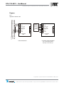
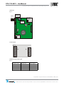
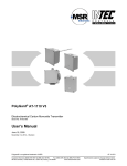
DT5-1112-2B11 – UserManual Specifications subject to change without notice. | USA 150929 | Page 1 of 19 PolyGard DT5-1112-2B11 Electrochemical Carbon Monoxide Transmitter with BACnet Interface Serial No. AT03-003 User Manual April 2012 September 29, 2015 – Revision Polygard® is a registered trademark of MSR | GAADT031110BAC_0412 Polygard® is a registered trademark of MSR GAADT031110BAC_0412 Customer Services (858) 578-7887 & (888) GO INTEC Fax (858) 578-4633 & (888) FX INTEC Specification subject to change without notice. 12700 Stowe100, Drive, Suite 100, Poway, CA 92064 www.inteccontrols.com | Ph: (858) 578.7887 & (888) GO.INTEC | relevantsolutions.com/inteccontrols Printed in USA 140916 INTEC Controls, 12700 Stowe Dr., Suite Poway, CA 92064 DT5-1112-2B11 – UserManual Page 02 Specifications subject to change without notice. | USA 150929 | Page 2 of 19 1 General Overview ............................................................................................................................... 3 2 Functional Description ...................................................................................................................... 3 2.1 2.2 3 Installation .......................................................................................................................................... 4 3.1 3.2 4 Addressing................................................................................................................................. 7 Manual Addressing..................................................................................................................... 7 BACnet Addressing .................................................................................................................... 7 Inspection and Service ...................................................................................................................... 8 7.1 7.2 7.3 8 Calibration .................................................................................................................................. 5 Manual Zero-Point Calibration ................................................................................................... 6 Manual Gain Calibration ............................................................................................................. 6 BACnet Mode ...................................................................................................................................... 7 6.1 6.2 6.3 7 Wiring Connection ...................................................................................................................... 5 Commissioning .................................................................................................................................. 5 5.1 5.2 5.3 6 Mounting Instructions ................................................................................................................. 4 Installation .................................................................................................................................. 4 Electrical Connection ........................................................................................................................ 4 4.1 5 Control Mode .............................................................................................................................. 3 Sensor ........................................................................................................................................ 3 Inspections ................................................................................................................................. 8 Calibration .................................................................................................................................. 8 Exchange of Sensor Element ..................................................................................................... 8 Troubleshooting ................................................................................................................................. 9 8.1 8.2 Analog Mode .............................................................................................................................. 9 BACnet Mode ............................................................................................................................. 9 9 Cross-sensitivity Data........................................................................................................................ 9 10 BACnet Specification ....................................................................................................................... 10 10.1 10.2 10.3 10.4 10.5 10.6 10.7 Bacnet Services .................................................................................................................... 10 BACnet BIBBs supported ..................................................................................................... 11 Reliability property handling ................................................................................................. 11 MS/TP Master Specification ................................................................................................. 11 Device Register description: available Properties ............................................................... 12 Analog Input1 Register description (internal CO Sensor) .................................................... 13 Analog Input2 Register description (external CO Sensor ) ................................................. 13 11 Technical Data .................................................................................................................................. 14 12 Figures .............................................................................................................................................. 16 13 Notes and General Information....................................................................................................... 19 13.1 13.2 13.3 13.4 Intended Product Application ................................................................................................ 19 Installers’ Responsibilities .................................................................................................... 19 Maintenance ......................................................................................................................... 19 Limited Warranty ................................................................................................................... 19 Polygard® is a registered trademark of MSR | GAADT031110BAC_0412 12700 Stowe Drive, Suite 100, Poway, CA 92064 | Ph: (858) 578.7887 & (888) GO.INTEC | relevantsolutions.com/inteccontrols Printed in USA 140916 DT5-1112-2B11 – UserManual Page 03 Specifications subject to change without notice. | USA 150929 | Page 3 of 19 Electrochemical Carbon Monoxide Transmitter 1 General Overview The PolyGard CO BACnet gas transmitter DT5-1112-2B11 with digital processing of the measuring values and temperature compensation is used for the continuous monitoring of the ambient air to detect the presence of carbon monoxide gas. Applications include underground / enclosed parking garages, tunnels, engine test stations, shelters, loading areas etc. The DT5-series transmitter is equipped with a serial interface including BACnet protocol and with an analog output where the signal can be selected as current signal (0)4-20 mA or as voltage signal (0)2-10 V. In the 4-20 mA mode the transmitter also works in the 2-wire technique. Addressing and calibration is done manually via push-buttons / potentiometers and address switches. The intended installations are all areas being directly connected to the public low voltage supply, e.g. residential, commercial and industrial ranges as well as small enterprises (according to EN50 082). The PolyGard® CO BACnet transmitter must NOT be used in potentially explosive atmospheres. 2 Functional Description 2.1 Control Mode The transmitter can be connected via RS 485 Interface / BACnet protocol to a vide variety of monitoring and control devices such as, Direct Digital Controllers, Single/Multi-point controllers, Building Management Systems, Personal Computers etc. In this mode there is an analog input for the connection of an additional 420 mA transmitter. The two measuring values are transmitted via the RS-485 interface / BACnet protocol. The cable topology for the RS-485 bus can be taken from the “Guidelines for wiring and commissioning of the DGC-05 hardware”. 2.2 Sensor The sensor portion of the transmitter is a sealed electro-chemical cell with two electrodes, sensing and reference. The ambient air to be monitored diffuses through a membrane filter into the liquid electrolyte of the sensor. The chemical process of the measurement is one of oxidation where one molecule of the target gas is exchanged for one molecule of oxygen. The reaction drives the oxygen molecule to the counter electrode, generating a DC microampere signal between the sensing and reference electrodes. This signal is linear to the volume concentration of the sensed gas. The signal is evaluated by the connected amplifier and transformed into a linear output signal. Electrochemical processes always lead by-and-by to a loss of sensitivity. Therefore calibration of zero-point and gain via BACnet or with the potentiometer “Gain” is necessary at regular intervals. Caution: There is a small quantity of corrosive liquid in the sensor element. If in case of damage persons or objects touch the liquid, you have to clean the affected areas as fast and carefully as possible with tap water. Out of use sensors must be disposed in the same way as batteries. Polygard® is a registered trademark of MSR | GAADT031110BAC_0412 12700 Stowe Drive, Suite 100, Poway, CA 92064 | Ph: (858) 578.7887 & (888) GO.INTEC | relevantsolutions.com/inteccontrols Printed in USA 140916 DT5-1112-2B11 – UserManual Page 04 Specifications subject to change without notice. | USA 150929 | Page 4 of 19 3 Installation Note: Avoid any force (e.g. by thumb) on the sensor element during operation or installation. Electronics can be destroyed by static electricity. Therefore, do not touch the equipment without a wrist strap connected to ground or without standing on a conductive floor (acc. to DIN EN100015). 3.1 Mounting Instructions When choosing the mounting site please pay attention to the following: • The specific weight of carbon monoxide is slightly less than that of air (factor 0.97). Recommended mounting height is 1.5 m (5 feet) to 1.8 m (6 feet) above floor. • Choose mounting location of the sensor according to the local regulations. • Consider the ventilation conditions! Do not mount the transmitter in the center of the airflow (air passages, suction holes). • Mount the transmitter at a location with minimum vibration and minimum variation in temperature (avoid direct sunlight). • Avoid locations where water, oil etc. may influence proper operation and where mechanical damage might be possible. • Provide adequate space around the sensor for maintenance and calibration work. • In areas where condensation may occur inside the electrical conduit, a sealing agent should be used if the conduit entry is at the top of the transmitter. Duct mounting • Mount only in a straight section of duct with minimum air vortex. Keep a minimum distance of 1 m (3,5 feet) from any curve or obstacle. • Mount only in a duct system with a maximum air velocity of 10 m/s (2000 ft/min) or less. • Mounting must be performed so that the probe openings are in line with the airflow. 3.2 Installation • Open the cover, Unplug basic PCB carefully from the wiring terminals. • Mount enclosure vertically to the wall. • Plug in the basic PCB at X4 and X5 with care, Replace the cover. 4 Electrical Connection Consider static electricity! See 3. Mounting • Installation of the electrical wiring should only be performed by a trained specialist according to the connection diagram, without any power applied to conductors and according to the corresponding regulations! • Avoid any influence of external interference by using shielded cables for the signal line, but do not connect the shield. • It is important to ensure that the wire shields or any bare wires do not short the mounted PCB. • Recommended cable for power and BACnet communications is 18 gage, two twisted shielded pair with all four wires being different colors (Connect-Air Wire & Cable W182P-247 or equivalent). When selecting and installing the cables you have to comply with the regulations concerning the RS 485 bus installation. The installations have to be executed in line topology. Cable length and type have to be considered as well. Polygard® is a registered trademark of MSR | GAADT031110BAC_0412 12700 Stowe Drive, Suite 100, Poway, CA 92064 | Ph: (858) 578.7887 & (888) GO.INTEC | relevantsolutions.com/inteccontrols Printed in USA 140916 DT5-1112-2B11 – UserManual Page 05 Specifications subject to change without notice. | USA 150929 | Page 5 of 19 4.1 Wiring Connection • Open the cover, Unplug basic PCB carefully from terminal blocks at X4 and X5. • Insert the cable and connect cable leads to terminal blocks. See fig. 1.and 2. • Replug the PCB in the terminal blocks X4, X5, Replace cover. 5 Commissioning Consider commissioning instructions at any exchange of sensor elements. Only trained technicians should perform the following: • Check mounting location. • Select output signal form Current or voltage, and starting point 0 or 20%. See fig. 4 • Check power voltage. • Check PCB for proper mounting at X4 and X5. • Change BACnet ID 1(delivery ID) to unique ID (defined from System Integrator) • Transmitter is factory calibrated and should not require adjustment at startup. Required instruments for commissioning (calibration) of the transmitter: • Test gas bottle with synthetic air of CO-free ambient air. • Test gas bottle with CO (ppm) in the range of 30 – 80 % of the measuring range. • Gas pressure regulator with flow meter to control the gas flow to 150 ml/min. • Calibration adapter with tube (INTEC model number CONKIT-E/CH-LC) • Digital voltmeter with range 0 – 300mV, accuracy 1% (for manual calibration). • Small screwdriver (for manual calibration). Note: Prior to calibration or verification, the sensor element must be fully stabilized by applying power voltage for at least 1 hour without interruption. Please observe proper handling procedures for test gas bottles (regulations TRGS 220)! Attention: CO calibration gas is toxic, never inhale the gas! Symptoms: Dizziness, headache and nausea. Procedure if exposed: Take the victim into fresh air at once, call a doctor. 5.1 Calibration Only manual calibration mode in combination with BACnet protocol is possible to calibrate the transmitter: Manual calibration Manual calibration is only possible if the transmitter is equipped with the push-button “Zero” and the potentiometer “Gain” (= version for manual calibration). The jumper V-A has to be set before manual calibration. Only by doing so the control voltage is available at the test pins X6. Remove the jumper after calibration. Polygard® is a registered trademark of MSR | GAADT031110BAC_0412 12700 Stowe Drive, Suite 100, Poway, CA 92064 | Ph: (858) 578.7887 & (888) GO.INTEC | relevantsolutions.com/inteccontrols Printed in USA 140916 DT5-1112-2B11 – UserManual Page 06 Specifications subject to change without notice. | USA 150929 | Page 6 of 19 5.2 Manual Zero-Point Calibration Consider the warm-up period of the sensor (at least 1 hour). • Connect calibration adapter carefully to the sensor element. • Apply synthetic air (150 ml/min; 1 Bar (14.5 psi ) ± 10%), or CO-free ambient air. • Wait 2 minutes until the signal is stable, push button “Zero” for 5 seconds. After successful calibration the measuring signal is corrected automatically. Depending on the selected signal starting point the measuring signal shows the following values: Signal start at 2 V or 4 mA 40 mV = 0 ppm Signal start at 0 V or 0 mA 0 mV = 0 ppm If the zero-point is out of the admissible range (> 20 mV at starting point 0% / > 60 mV at starting point (20%) before calibration, there is no correction of the measuring signal. The sensor has to be replaced. • Remove calibration adapter carefully by turning lightly. Check the sensor for correct mounting! 5.3 Manual Gain Calibration • Connect calibration adapter carefully to the sensor element. • Apply calibration test gas CO (150 ml/min; 1 Bar (14.5 psi) ± 10%). • Wait two minutes until the signal is stable, adjust control voltage with potentiometer ”Gain” until the signal corresponds to the calculated value ± 3 mV, see Calculation of Control Voltage. By limiting the gain factor, calibration will not be possible any more when the sensitivity of the sensor reaches a residual sensitivity of 30 %. Then the sensor has to be replaces. • Remove calibration adapter with a careful light turn. Check the sensor for correct mounting! Calculation of Control Voltage Signal start 2 V / 4 mA Control voltage (mV) = 160 (mV) x test gas concentration CO (ppm) measuring range CO (ppm) = 200 (mV) x test gas concentration CO (ppm) measuring range CO (ppm) + 40 (mV) Signal start 0 V / 0 mA Control voltage (mV) Example: Measuring range 300 ppm Test gas concentration 242 ppm CO Control voltage: Signal start 2 V / 4 mA 169 mV Control voltage: Signal start 0 V / 0 mA 161,3 mV Signal start 2 V / 4 mA Signal start 0 V / 0 mA 160 (mV) x 242 (ppm) + 40 (mV) = 169 mV 300 (ppm) 200 (mV) x 242 (ppm) 300 (ppm) = 161,3 mV Polygard® is a registered trademark of MSR | GAADT031110BAC_0412 12700 Stowe Drive, Suite 100, Poway, CA 92064 | Ph: (858) 578.7887 & (888) GO.INTEC | relevantsolutions.com/inteccontrols Printed in USA 140916 DT5-1112-2B11 – UserManual Specifications subject to change without notice. | USA 150929 | Page 7 of 19 6 Addressing Depending on the hardware version MS/TP addressing of the transmitter is done via an address switch. 6.1 Manual Addressing MS/TP Manual addressing is accomplished via the 16-position rotary address switch and a jumper for selecting the 4 address ranges. Transmitters ordered with the “high address range” option (order code “H”) can be addressed in the range of 61-120. Firmware in the transmitter adds 60 to the value selected in the table below. Position 4 3 2 1 Switch position 0 1 2 3 4 5 6 7 8 9 A B C D E F Jumper pos. 01 = address inactive 01 02 03 04 05 06 07 08 09 10 11 12 13 14 15 Jumper pos. 02 = address inactive 16 17 18 19 20 21 22 23 24 25 26 27 28 29 30 Jumper pos. 03 = address inactive 31 32 33 34 35 36 37 38 39 40 41 42 43 44 45 Jumper pos. 04 = address inactive 46 47 48 49 50 51 52 53 54 55 56 57 58 59 60 6.2 BACnet Addressing In addition to selecting the MS/TP address, the BACnet address must also be selected. According to BACnet Rules, the BACnet address must be unique within the entire system. Typically this will be assigned by the BACnet System Integrator. Version 0.1 : In Device Object- Object Identifier- Instance Number is settable to unique Number from 1 to 4194299 This can be done with all BACnet Software Tools , which allow changing Data of Device Object- Object Identifier After changing this parameter, the transmitter must be powered off and on again! Polygard® is a registered trademark of MSR | GAADT031110BAC_0412 12700 Stowe Drive, Suite 100, Poway, CA 92064 | Ph: (858) 578.7887 & (888) GO.INTEC | relevantsolutions.com/inteccontrols DT5-1112-2B11 – UserManual Page 08 Specifications subject to change without notice. | USA 150929 | Page 8 of 19 7 Inspection and Service 7.1 Inspections Inspection, service and calibration of the transmitters should be done by trained technicians and executed at regular intervals. We therefore recommend concluding a service contract with INTEC Controls or one of their authorized partners. 7.2 Calibration (See section 5.1 ;5.2 and 5.3) • Calibration should be performed at periodic intervals as determined by the person responsible for the gas detection system (recommendation every 12 months). • After exchange of the sensor • If in case of operational or climatic influences the sensitivity of the sensor falls below 70 % in operation, calibration will not be possible any more. Then the sensor has to be changed. 7.3 Exchange of Sensor Element Consider static electricity! See point 3. Sensor should always be installed without power applied: • Unplug basic PCB carefully from the wiring terminals. • Unplug old sensor element from the PCB. • Take the new sensor out of the original packing. • Plug in the sensor element into the PCB at X3/X7. • Replug the PCB into terminal blocks X4, X5 carefully. • Transmitter must be recalibrated according to section 5. Polygard® is a registered trademark of MSR | GAADT031110BAC_0412 12700 Stowe Drive, Suite 100, Poway, CA 92064 | Ph: (858) 578.7887 & (888) GO.INTEC | relevantsolutions.com/inteccontrols Printed in USA 140916 DT5-1112-2B11 – UserManual Page 09 Specifications subject to change without notice. | USA 150929 | Page 9 of 19 8 Troubleshooting 8.1 Analog Mode Trouble Output signal < 3 mA / 1,5 V and/or control voltage < 30 mV only for starting signal 2V/4 mA Cause Solution Jumper 0-20 % not set Check jumper position Power voltage not applied Measure tension at X4: Two-wire: Pin 1 (+) and 4 (-) Three-wire: Pin 1 (+) and 2 (-) PCB AT03 not plugged in correctly at X4 and X5 Replug PCB correctly Wire break Check the wiring Output signal > 22 mA /220 mV Short-circuit Check the wiring Control voltage does not reach the calculated value Sensor element not calibrated Calibrate sensor element Sensor sensitivity < 30 % Replace sensor element No reaction of the output signal in Power voltage not applied spite of gas concentration Signal (Pin 4) not wired correctly 8.2 Measure tension at X4 Check the wiring BACnet Mode Trouble Yellow LED not shining Cause Solution Power voltage not applied Measure tension at X4: Pin 1 (+) and 2 (-) PCB not plugged in correctly at X4/X5 Replug PCB correctly Wire break Check wiring Yellow LED not flashing No communication at the transmitter Transmitter not addressed, check bus wiring incl. topology and termination Voltage < 16 V No control voltage at calibration Jumper V-A not set Set the jumper. Remove it after calibration! 9 Cross-sensitivity Data The cross sensitivity (influence on the gas concentration value by gasses other than carbon monoxide) can be read from the table Technical Data (see 9.). Other gases can have an influence on the sensitivity, too. The table does not claim to be complete. The indicated sensitivity data are only standard values referring to new sensor elements. Polygard® is a registered trademark of MSR | GAADT031110BAC_0412 12700 Stowe Drive, Suite 100, Poway, CA 92064 | Ph: (858) 578.7887 & (888) GO.INTEC | relevantsolutions.com/inteccontrols Printed in USA 140916 DT5-1112-2B11 – UserManual Page 10 Specifications subject to change without notice. | USA 150929 | Page 10 of 19 10 BACnet Specification BACnet Standardized Device Profile BACnet Networks allow Peer to Peer Communication. DGC05-Bacnet-Interface supports functions that fit the BACnet profile called an "Application Specific Controller" (B-ASC). 10.1 BACnet Services DGC05-Bacnet-Interface supports the following BACnet protocol services: 1. Who-Is (Execute) Upon receipt of a Who-Is request, EasyBAC initiates an I-Am request, as appropriate, using Device object's properties values for service request parameters. 2. I-Am (Initiate) DGC05-Bacnet-Interface initiates I-Am requests filled with Device object's properties values in the following situations: · at start-up · upon receipt of a Who-Is request ReadProperty (Execute) all properties present in the Object Database are readable. Upon receipt of a Read Property request, DGC05-Bacnet-Interface performs request validation and sends back an acknowledgement, as defined by the BACnet standard. In case of a success. DGC05-Bacnet-Interface sends back to the BACnet network positive acknowledgement (ReadProperty-ACK) containing current value of the requested property from the BACnet Object Database. In case of a failure, DGC05-Bacnet-Interface sends negative acknowledgement (BACnet-Error) with appropriate BACnet error class and error code. Current value of a property in the Database may originate from: • • • DGC05-Bacnet-side DGC05-Controller Another BACnet device (set by means of a WriteProperty BACnet service request) WriteProperty (Execute) Most of the properties in the BACnet Object Database are not writeable and cannot be changed by means of a WriteProperty service request. See Object Types Supported for complete list of writeable properties in each supported object type. Upon receipt of a valid WriteProperty request, DT% BACnet transmitter writes to the Virtual Object Database specified value of the specified property of the specified object and sends back to the BACnet network positive acknowledgement, as defined by the BACnet standard. In case of a failure DGC05-Bacnet-Interface sends negative acknowledgement. If the property being written is Present value or Relinquish default, and the object in question is not out of service (see Handling out Of Service Property), new property value is sent to the DT5 BACnet-Transmitter. FB: Output Property serial message is sent a synchronously and may be sent to the microprocessor either after or before BACnet acknowledgement is actually sent over the BACnet network. DT5-Bacnet-Transmitter WriteProperty handler performs basic request validity checks, such as existence of the object specified, existence and write ability of the property specified. Standardmandated BACnet logic is also implemented: see handling Command Priorities and Out_Of_Service handling. However, application-level checks, such as checking Present_Value against device-specific bounds, are not performed. Polygard® is a registered trademark of MSR | GAADT031110BAC_0412 12700 Stowe Drive, Suite 100, Poway, CA 92064 | Ph: (858) 578.7887 & (888) GO.INTEC | relevantsolutions.com/inteccontrols Printed in USA 140916 DT5-1112-2B11 – UserManual Page 11 Specifications subject to change without notice. | USA 150929 | Page 11 of 19 10.2 BACnet BIBBs supported The BACnet standard defines a concept called BIBBs (BacNET Interoperability Building Blocks). A BIBB is a simple definition of a specific set of BacNET features that must be implemented by a device to support that BIBB. The DT5-Bacnet-Transmitter is capable of performing the functionality of the following BIBBs: · DS-RP-B that means DS (data sharing), RP (read property), B (Server device) · DS-WP-B that means DS (data sharing), WP (write property), B (Server device) · DM-DDB-B that means DM (device management), DDB (Dynamic Device Binding), B (Server device) The "DDB" description means that this device can find another device on the network. This set of BIBBs matches the BACnet B-ASC profile (without support for Who-Has/I-Have and DCC - Device Communications Control) 10.3 Reliability property handling DGC05-Bacnet-Interface checks all possible DGC05 –Bus-Nodes for his correct functionality. If a Sensor- or Relay Module is not available, damaged or not activated: Input property with property ID set to Reliability DGC05-Bacnet-Interface automatically updates FAULT flag in the Status Flags property in the BACnet Object Database: sets it if new Reliability value is not equal to NO_FAULT_DETECTED, and clears it otherwise. 10.4 MS/TP Master Specification Interface Settings Baud: Start bit Stop bit Parity MS/TP MAC Address 38400 (others on request) 1 1 No See 6.2 Fixed internal program definitions without properties Max Master Max Info Frames 127 1 Polygard® is a registered trademark of MSR | GAADT031110BAC_0412 12700 Stowe Drive, Suite 100, Poway, CA 92064 | Ph: (858) 578.7887 & (888) GO.INTEC | relevantsolutions.com/inteccontrols Printed in USA 140916 DT5-1112-2B11 – UserManual Page 12 Specifications subject to change without notice. | USA 150929 | Page 12 of 19 10.5 Device Register description: available Properties Name Default Value R/W Notes APDU Timeout App Software Version 3000 DTF-BNK V0.1 R R Timeout in ms BACnet Stack Version Database Revision 1 R Description R/W Firmware Revision DTF-BNK V0.1 R Max APDU Length Accepted 480 R Model Name Number of APDU Retries Object Identifier AT03-XXXXX 3 R R DEVICE, 1 R/W Object List: DEVICE ANALOG_INPUT0 ANALOG_INPUT1 1 0 1 Changeable by BacNet Integrator Changeable by BacNet Integrator R Object Name R/W Object Type DEVICE(8) R Protocol Conformance Class 1 R Protocol Objects Supported ANALOG_INPUT, DEVICE R Protocol Services Supported READ_PROPERTY, READ_PROPERTY_MULTIPLE, I_AM, WHO_IS R Protocol Version Protocol Revision Segmentation Supported System Status Vendor Identifier Vendor Name 1 1 NO_SEGMENTATION(3) OPERATIONAL(0) 532 MSR Electronic GmbH R R R R R R Changeable by BacNet Integrator Not Available Properties The following optional properties are not present: Location, Max_Segments_Accepted, VT_Classes_Supported, Active_VT_Sessions, Local_Time, Local_Date, UTC_Offset, Daylight_Savings_Status, APDU_Segment_Timeout, List_Of_Session_Keys, Time_Synchronization_Recipients, Max_Master, Max_Info_Frames, Configuration_Files, Last_Restore_Time, Backup_Failure_Timeout, Active_COV_Subscriptions, Slave_Proxy_Enable, Manual_Slave_Address_Binding, Auto_Slave_Discovery, Slave_ Address_Binding, Profile_Name. Polygard® is a registered trademark of MSR | GAADT031110BAC_0412 12700 Stowe Drive, Suite 100, Poway, CA 92064 | Ph: (858) 578.7887 & (888) GO.INTEC | relevantsolutions.com/inteccontrols Printed in USA 140916 DT5-1112-2B11 – UserManual Page 13 Specifications subject to change without notice. | USA 150929 | Page 13 of 19 10.6 Analog Input1 Register description (internal CO Sensor) Name Default Value R/W Notes Description Descr_AI0 R/W Event State STATE_NORMAL(0) R Changeable by BacNet Integrator Object Identifier 0 R Object Name Carbon Monoxide R/W Object Type ANALOG_INPUT(0) R Present Value Units R PARTS_PER_MILION(96) Changeable by BacNet Integrator Current Gas Value R 10.7 Analog Input2 Register description (external CO Sensor ) Name Default Value R/W Notes Description Descr_AI1 R/W Event State STATE_NORMAL(0) R Changeable by BacNet Integrator Object Identifier 1 R Object Name External Transmitter R/W Object Type ANALOG_INPUIT(0) R Present Value Units R PARTS_PER_MILION(96) Changeable by BacNet Integrator Current Gas Value R Not Available Properties: The following optional properties are not present: Update_Interval, COV_Increment, Time_Delay, Notification_Class, High_Limit, Low_Limit, Deadband, Limit_Enable, Event_Enable, Acked_Transitions, Notify_Type, Event_Time_Stamps, Profile_Name. Dynamic Properties: This Analogue Input Object reflects the Current Value Information from Digital Gas Sensors . During Normal Operation Properties - Present value and - Status Flags will be updated by ADT Transmitter Polygard® is a registered trademark of MSR | GAADT031110BAC_0412 12700 Stowe Drive, Suite 100, Poway, CA 92064 | Ph: (858) 578.7887 & (888) GO.INTEC | relevantsolutions.com/inteccontrols Printed in USA 140916 DT5-1112-2B11 – UserManual Page 14 Specifications subject to change without notice. | USA 150929 | Page 14 of 19 11 Technical Data General sensor performances Gas type Carbon monoxide (CO) Sensor element Electrochemical, diffusion Measuring range (standard, other ranges 0 - 300 ppm (ex works) according to the data sheet) adjustable between 0-150 and 0-300 ppm Pressure range Atmosphere ± 15 % Humidity 15 – 90 % RH non condensing Storage temperature range 5 °C to 30 °C (41 °F to 86 °F) Storage time Max. 6 months Mounting height 1,5 to 1,8 m ( 5 to 6 ft.) Type DT5-1112 Accuracy ± 3 ppm Repeatability ± 3 % of reading Long-term output drift < 5% signal loss/year Response time t90 < 50 sec. Life expectancy > 5 years/normal operating environment Humidity range – short-term 0 – 95 % RH non condensing Temperature range - continuous -10 °C to + 50 °C (14 °F to 122 °F) Temperature range – short-term -20 °C to + 50 °C (-4 °F to 122 °F) Cross sensitivity* Concentration (ppm) Reaction (ppm CO) Acetone, C3H6O 1000 0 Acetylene, C2H2 40 80 Ammonia, NH3 100 0 Chlorine, Cl2 2 0 Ethanol, C2H5OH 2000 5 Iso Propanol, C3H8O 200 0 Carbon dioxide, CO2 5000 0 Nitrogen dioxide, NO2 50 -1,0 Nitric oxide, NO 50 8 Sulphur dioxide, SO2 50 < 0,5 Hydrogen Sulphide, H2S 25 0 Hydrogen, H2 100 20 * The table doesn’t claim to be complete. Other gases, too, can have an influence on the sensitivity. The mentioned cross sensitivity data are only reference values valid for new sensors. Polygard® is a registered trademark of MSR | GAADT031110BAC_0412 12700 Stowe Drive, Suite 100, Poway, CA 92064 | Ph: (858) 578.7887 & (888) GO.INTEC | relevantsolutions.com/inteccontrols Printed in USA 140916 DT5-1112-2B11 – UserManual Page 15 Specifications subject to change without notice. | USA 150929 | Page 15 of 19 Electrical Power supply Power consumption Mode (without options) - Analog mode - Bus mode Output signal Analog output signal Selectable: Current / voltage Starting point 0 / 20 % Serial interface Transceiver Protocol Physical Enclosure* Enclosure color* Dimensions* (H x W x D) Weight* Protection class* Mounting* Cable entry Wire connection Approval 18 - 28 VDC, reverse polarity protected 22 mA, max. (0,6 VA) 12 mA, max. (0,3 VA) (0) 4 – 20 mA, load ≤ 500 Ω, (0) 2 - 10 V; load ≥ 50 k Ω proportional, overload and short-circuit proof RS 485 / 38400 Baud BACnet Polycarbonate, UL 94-HB fire retardant Light gray 5.12 x 3.70 x 2.25 in. (130 x 94 x 57 mm) Approx. (0.6 Ibs.) (0.25 kg) IP 65 Wall mounting, pillar mounting ½” conduit Screw-type terminal min. 0,25, to. 2,5 mm2 24 to 14 AWG VDI 2053 German air treatment systems for car parks UL2075 ; UL61010-1 EMC Directive 2004 / 108 / EWG CE Guidelines Options Analog input Only for RS-485 mode Power supply for external transmitter 4 – 20 mA overload and short-circuit proof, input resistance 200 Ω 24 VDC max. 50 mA Polygard® is a registered trademark of MSR | GAADT031110BAC_0412 12700 Stowe Drive, Suite 100, Poway, CA 92064 | Ph: (858) 578.7887 & (888) GO.INTEC | relevantsolutions.com/inteccontrols Printed in USA 140916 DT5-1112-2B11 – UserManual Page 16 Specifications subject to change without notice. | USA 150929 | Page 16 of 19 Figures Fig. 1 Application: BACnet mode 1 2 3 4 5 X5 Analog Transmitter 4-20 mA 0 VDC 24 VDC 7 Bus_B 6 Bus_A 5 4-20 mA_Inp 4 Analog_Out 3 24 VDC_Out 2 0 VDC 1 24 VDC X4 Transmitter DT5 1 2 3 4 5 X5 24 VDC 0 VDC Bus_A Bus_B 7 Bus_B 6 Bus_A 5 4-20 mA_Inp 4 Analog_Out 3 24 VDC_Out 2 0 VDC 1 24 VDC X4 Transmitter DT5 Connection field bus Connection analog transmitter - Two- or three-wire connection, depending on transmitter type Polygard® is a registered trademark of MSR | GAADT031110BAC_0412 12700 Stowe Drive, Suite 100, Poway, CA 92064 | Ph: (858) 578.7887 & (888) GO.INTEC | relevantsolutions.com/inteccontrols Printed in USA 140916 DT5-1112-2B11 – UserManual Page 17 Specifications subject to change without notice. | USA 150929 | Page 17 of 19 PCB AT03 Fig. 2 Anal. Ouput Start Point = 20 % =0% Manual Calibration Gain Position 4 3 2 1 Manual Addressing 0-20% 7 X5 Zero 6 1 2 4 3 Test 5 3 4 V-A 2 1 X4 5 Sensor XA3-1 XA3-2 Anal. Output = V DC = mA Terminal block 1 2 3 4 5 1 2 3 4 5 6 7 X4 X5 Selection analog output signal Fig. 3 Jumper 0- 20 % Jumper V-A Output signal Not set Not set 0 – 20 mA Set Not set 4 – 20 mA Not set Set 0 – 10 V Set Set 2 – 10 V Polygard® is a registered trademark of MSR | GAADT031110BAC_0412 12700 Stowe Drive, Suite 100, Poway, CA 92064 | Ph: (858) 578.7887 & (888) GO.INTEC | relevantsolutions.com/inteccontrols Printed in USA 140916 DT5-1112-2B11 – UserManual Page 18 Specifications subject to change without notice. | USA 150929 | Page 18 of 19 Calibration adapter Fig. 5 Type: CONKIT-E/CH-LC Polygard® is a registered trademark of MSR | GAADT031110BAC_0412 12700 Stowe Drive, Suite 100, Poway, CA 92064 | Ph: (858) 578.7887 & (888) GO.INTEC | relevantsolutions.com/inteccontrols Printed in USA 140916 DT5-1112-2B11 – UserManual Page 19 Specifications subject to change without notice. | USA 150929 | Page 19 of 19 12 Notes and General Information It is important to read this user manual thoroughly and clearly in order to understand the information and instructions. The PolyGard® transmitters must be used within product specification capabilities. The appropriate operating and maintenance instructions and recommendations must be followed. Due to on-going product development, MSR and INTEC Controls reserve the right to change specifications without notice. The information contained herein is based upon data considered to be accurate. However, no guarantee is expressed or implied regarding the accuracy of this data. 12.1 Intended Product Application The PolyGard® transmitters are designed and manufactured for control applications and air quality compliance in commercial buildings and manufacturing plants (i.e. detection and automatic exhaust fan control for automotive maintenance facilities, enclosed parking garages, engine repair shops, warehouses with forklifts, fire stations, tunnels, etc.). 12.2 Installers’ Responsibilities It is the installer’s responsibility to ensure that all PolyGard® transmitters are installed in compliance with all national and local codes and OSHA requirements. Installation should be implemented only by technicians familiar with proper installation techniques and with codes, standards and proper safety procedures for control installations and the latest edition of the National Electrical Code (ANSI/NFPA70). It is also essential to follow strictly all instructions as provided in the user manual. 12.3 Maintenance It is recommended to check the PolyGard® transmitter regularly. Due to regular maintenance any performance deviations may easily be corrected. Re-calibration and part replacement in the field may be implemented by a qualified technician and with the appropriate tools. Alternatively, the easily removable plug-in transmitter card with the sensor may be returned for service to MSR-Electronic-GmbH. 12.4 Limited Warranty MSR-Electronic-GmbH and INTEC Controls warrants the PolyGard® transmitter for a period of two years, 12 months normal exposure for the sensor, from the date of shipment against defects in material or workmanship. Should any evidence of defects in material or workmanship occur during the warranty period, INTEC Controls will repair or replace the product at their own discretion, without charge. This warranty does not apply to units that have been altered, had attempted repair, or been subject to abuse, accidental or otherwise. The warranty also does not apply to units in which the sensor element has been overexposed or gas poisoned. The above warranty is in lieu of all other express warranties, obligations or liabilities. This warranty applies only to the PolyGard® transmitter. MSR-Electronic-GmbH and/or INTEC Controls shall not be liable for any incidental or consequential damages arising out of or related to the use of the PolyGard® transmitter. If the PolyGard® transmitter needs to be returned to INTEC Controls for service, an RMA number must be obtained prior to sending. Polygard® is a registered trademark of MSR | GAADT031110BAC_0412 12700 Stowe Drive, Suite 100, Poway, CA 92064 | Ph: (858) 578.7887 & (888) GO.INTEC | relevantsolutions.com/inteccontrols Printed in USA 140916


![[PSS 21S-2B11 B4] Field Device Manager for IACC and](http://vs1.manualzilla.com/store/data/005879688_1-2c218fc20ab8a2ac5340bc4e42ae00e6-150x150.png)