1
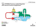
Drive Module
Site Preparation Guide
DF1153-E1, First Edition
This document contains proprietary information of LSI Logic Corporation. The
information contained herein is not to be used by or disclosed to third parties without the
express written permission of an officer of LSI Logic Corporation. Any product(s)
described herein is/are a licensed product of LSI Logic Corporation.
Document DF1153-E1, First Edition. March 2001
This document describes models E3300, FC-1 10x, FC-1 14x, E2400 10x, and E2400 14x of
LSI Logic Corporation’s drive modules and command modules and will remain the official
reference source for all revisions/releases of this product until rescinded by an update.
It is the policy of LSI Logic to improve products as new technology, components, software,
and firmware become available. LSI Logic Corporation reserves the right to make changes
to any products herein at any time without notice. All features, functions, and operations
described herein may not be marketed by LSI Logic in all parts of the world. In some
instances, photographs and figures are of equipment prototypes. Therefore, before using
this document, consult you LSI Logic representative for information that is applicable and
current. LSI LOGIC DOES NOT ASSUME ANY RESPONSIBILITY OR LIABILITY FOR
THE USE OF ANY PRODUCT(S) DESCRIBED HEREIN EXCEPT AS EXPRESSLY
AGREED TO IN WRITING BY LSI LOGIC. The purchase of use of an LSI Logic product
does not convey a license under any patent, copyright, trademark, or other intellectual
property right of LSI Logic or third parties.
Copyright © 2001. LSI Logic Corporation. All rights reserved.
Trademark Acknowledgments
LSI Logic and the LSI Logic logo are registered trademarks of LSI Logic Corporation.
Adobe, Acrobat, and Acrobat Reader are either registered trademarks or trademarks of
Adobe Systems Incorporated. All other brand and product names may be trademarks of
their respective companies.
Federal Communications Commission (FCC) Radio
Frequency Interference Statement
This equipment has been tested and found to comply with the limits for a Class A digital
device, pursuant to Part 15 of the FCC Rules. These limits are designed to provide
reasonable protection against harmful interference in a commercial installation. This
equipment generates, uses, and can radiate radio frequency energy and, if not installed and
used in accordance with the instructions, may cause harmful interference to radio
communications. Operation of this equipment in a residential area is likely to cause
harmful interference, in which case the user will be required to correct the interference at
his own expense.
LSI Logic Corporation is not responsible for any radio or television interference caused by
unauthorized modification of this equipment or the substitution or attachment of
connecting cables and equipment other than those specified by LSI Logic Corporation. It is
the user’s responsibility to correct interference caused by such unauthorized modification,
substitution, or attachment.
This Class A digital apparatus meets all requirements of the Canadian Interference-Causing
Equipment Regulations.
Cet appareil numérique de la classé A respecte toutes les exigences du Règlement sure le
matèriel brouilleur du Canada.
Drive Module Site Preparation Guide
i
Revision Record
Edition or Revision
Date
First Edition
March 2001
Affected Pages/Remarks
New Book
Part Number: DF1153-E1
ii
Drive Module Site Preparation Guide
Contents
About This Book .............................................................................................................................. 1
Intended Readers ....................................................................................................................... 1
Content and Organization ......................................................................................................... 2
Terminology Used in This Book ............................................................................................... 2
Documentation Set .......................................................................................................................... 4
General Documentation ............................................................................................................ 4
Hardware Documentation ........................................................................................................ 4
Software Documentation ........................................................................................................... 4
Preparatory Tasks ............................................................................................................................ 5
Tools and Equipment You May Need ...................................................................................... 5
Area Requirements .......................................................................................................................... 6
Weights ....................................................................................................................................... 6
Dimensions ............................................................................................................................... 12
Airflow ...................................................................................................................................... 16
Environmental Requirements ....................................................................................................... 17
Site Wiring Requirements ............................................................................................................. 19
Site Wiring and Voltages ......................................................................................................... 19
Drive Module Power Requirements ............................................................................................. 21
E3300 Drive Module ................................................................................................................ 21
Power Connections ............................................................................................................ 21
Power Cord Routing ........................................................................................................... 22
FC-1 10x Drive Module and E2400 10x Command Module ................................................ 23
Power Cord Routing ........................................................................................................... 24
FC-1 14x Drive Module and E2400 14x Command Module ................................................ 25
Power Cord Routing ........................................................................................................... 26
Drive Module Site Preparation Guide
iii
Drive Module Cable Requirements ...............................................................................................27
E3300 Interface Cables .............................................................................................................27
SCSI Terminators ................................................................................................................27
FC-1 10x, E2400 10x, FC-1 14x, and E2400 14x Interface Cables .........................................28
iv
Drive Module Site Preparation Guide
List of Figures
1 E3300 Drive Module Dimensions ............................................................................................. 13
2 FC-1 10x Drive Module and E2400 10x Command Module Dimensions .............................. 14
3 FC-1 14x Drive Module and E2400 14x Command Module Dimensions .............................. 15
4 Drive Module or E2400 Command Module Airflow ............................................................... 16
5 Redundant AC Power Connections to Rackmount Controller and Drive Modules .............. 24
6 Redundant AC Power Connections to Rackmount Controller and Drive Modules .............. 26
Drive Module Site Preparation Guide
v
List of Tables
1 Unique Terminology and Concepts .............................................................................................3
2 E3300 Drive Module Weight Table ..............................................................................................7
3 FC-1 10x Drive Module Weight Table .........................................................................................8
4 E2400 10x Command Module Weight Table ..............................................................................9
5 FC-1 14x Drive Module Weight Table .......................................................................................10
6 E2400 14x Command Module Weight Table ............................................................................11
7 Shipping Carton Dimensions .....................................................................................................15
8 Drive Module and E2400 Command Module Environmental Requirements ........................17
9 Drive Module and E2400 Command Module Heat Dissipation ..............................................18
10 Drive Module and E2400 Command Module Site Wiring Voltages ......................................20
11 E3300 Power Requirements ......................................................................................................21
12 FC-1 10x and E2400 10x Power Requirements .......................................................................23
13 FC-1 14x and E2400 14x Power Requirements .......................................................................25
14 SCSI Drive Interface Cables ......................................................................................................27
15 Fibre Channel Host and Drive Interface Cables ......................................................................28
vi
Drive Module Site Preparation Guide
a
About This Book
This book provides technical specifications and information you will need to prepare a site
before installing the following hardware:
•
E3300 Drive Module containing up to ten drives and one low-voltage-differential- tosingle-ended environmental services monitor (LVD-SE ESM),
•
•
E3300 Drive Module containing up to ten drives and one LVD-LVD ESM
•
E2400 10x Command Module containing up to ten drives and one or two 2772
controllers
•
•
FC-1 14x Drive Module containing up to fourteen drives and one or two FC-FC ESMs
FC-1 10x Drive Module containing up to ten drives and one or two Fibre-Channel-toFibre-Channel (FC-FC) ESMs
E2400 14x Command Module containing up to fourteen drives and one or two 2772
controllers
Intended Readers
This book is intended for end users, system operators, system administrators, and service
technicians who are responsible for preparing and installing hardware. Readers should
understand the following technologies:
•
•
•
Redundant array of independent disk (RAID)
Small computer systems interface (SCSI)
Fibre Channel
Drive Module Site Preparation Guide
1
..............................................................................
Content and Organization
Site preparation information covered in this book includes:
•
Area requirements – drive module and E2400 command module weight, dimensions,
and airflow to help you determine installation, service, and operating floor space
requirements
•
Environmental requirements – temperature, humidity, and altitude ranges to help you
determine heating and air conditioning requirements
•
Power requirements – drive module E2400 command module voltages and power
requirements to help you prepare the site wiring
•
Interface requirements – interface cable types and lengths to help you determine which
cables to order
Terminology Used in This Book
The following table contains a list of terminology and definitions that are unique to the
products supported in this documentations set. For additional information on
terminology and concepts, see Understanding SANtricity™ Storage Manager Concepts
Guide for Version 7.10.
2
Drive Module Site Preparation Guide
. . . . . . . . . . . . . . . . . . . . . . . . . . . . . . . . . . . . . . . . . . . . . . . . . . . . . . . . . . . . . . . . About This Book
Table 1 Unique Terminology and Concepts
Term
Definition
Usage Examples
canister
Portable, removable container for components. Also
known as CRU.
controller canister
command
module
Compact unit that contains one or two controllers,
power supplies, and fans. Note: The E2400 command
module also contains disk drives. Also known as
controller module or controller tray.
command module
drive module
Compact unit that contains disk drives, power supplies,
one or two ESMs, and fans. Also known as drive tray or
expansion drive module.
drive module
ESM
Environmental Services Monitor. Interface board that
provides interface connections between the drive
modules and the SCSI bus, and environmental
information about the drive module to the host. Also
known as ESM CRU, ECC, or environmental card.
ESM canister
GBIC
light
Gigabit interface converter. A device used in Fibre
Channel networks to convert copper fibre signals to
fiber optic and vice versa.
copper GBIC minihub
copper GBIC module
optical GBIC minihub
optical GBIC module
Lights that glow or blink to indicate either a normal
operating status or hardware error. Also known as LEDs.
indicator light
Power light
Fault light
Drive Module Site Preparation Guide
3
..............................................................................
Documentation Set
The Drive Module Site Preparation Guide is part of a documentation set that provides
planning, installation, operation, and servicing information for SANtricity™ Storage
Manager software, command modules (E3300, E4400), drive modules (E3300, FC-1 10x,
FC-1 14x) and command modules (E2400 10x, E2400 14x). The documentation set
includes:
General Documentation
•
Roadmap.pdf file contains descriptions of and hyperlinks to the Adobe® Portable
Document Format (PDF) files that are stored on the software compact disk (CD). PDFs
are electronic versions of this document set.
•
Product Release Notes for SANtricity™ Storage Manager contains important information
about the CD contents, known restrictions and workarounds, and last minute updates
to the product documentation. This guide is shipped in printed form only.
Hardware Documentation
•
Command Module Site Preparation Guide contains site requirements and other
technical information for preparing the building for a command module installation.
•
Command Module and Drive Module Installation Guide contains step-by-step
instructions for installing deskside and rackmount command modules, drive modules,
and E2400 command modules, including switch setting information and cabling
routing examples.
•
Command Module User Guide contains model specifications and step-by-step
instructions for operating, upgrading, maintaining, and servicing the command
module and its components.
•
Drive Module User Guide contains model specifications and step-by-step instructions
for operating, upgrading, maintaining, and servicing the drive module, E2400
command modules, and their components.
Software Documentation
4
•
Storage System Planning Guide contains technical information and planning worksheets
to help you prepare for software installation.
•
SANtricity™ Storage Manager Installation Guide for Version 7.10 contains step-by-step
instructions for installing and upgrading the storage management software.
•
Understanding SANtricity™ Storage Manager Concepts Guide for Version 7.10 contains
explanations of the storage management software terminology, concepts and features.
Drive Module Site Preparation Guide
. . . . . . . . . . . . . . . . . . . . . . . . . . . . . . . . . . . . . . . . . . . . . . . . . . . . . . . . . . . . . . Preparatory Tasks
Preparatory Tasks
Before starting the installation process, you should complete the following tasks:
•
Make sure that the installation site meets all area, environmental, and power
requirements discussed in this book.
•
Order all necessary equipment and kits, including:
•
•
•
Hosts and host adapters
Interface cables
Mounting hardware and blank panel kits (for rackmount installations only)
•
•
Install all applicable hosts, host adapters, and command modules.
•
Attach the interface cables to the appropriate command modules and route them to the
area in which you intend to install the drive modules.
If you are preparing a rackmount installation, move the rackmount cabinet to its final
location and install all optional equipment (support rails, panels, command modules,
etc.). Route all power and auxiliary cables in the cabinet.
Tools and Equipment You May Need
To complete the installation procedure, you need the following items:
•
•
•
•
•
•
•
Two power cords (shipped with unit)
Screwdrivers and wrenches (various sizes)
Antistatic protection (such as a grounded wrist strap)
Interface cables, terminators, and tie wraps
Mounting hardware (for rackmount installations only)
Table or cart (optional)
Storage management software (to configure the disk array)
Drive Module Site Preparation Guide
5
..............................................................................
Area Requirements
The floor space at the installation site must provide:
•
Enough stability to support the weight of the drive module or E2400 command
module, and associated equipment (see "Weights" on this page)
•
Sufficient space to install, operate, and service the drive module or E2400 command
module (see "Dimensions" on page 12 and "Airflow" on page 16)
Weights
The drive module’s or E2400 command module’s total weight depends on the number of
components installed in the chassis. Refer to the following weight tables for information
on each model:
•
•
•
•
•
6
E3300 drive module – see Table 2 on page 7
FC-1 10x drive module – see Table 3 on page 8
E2400 10x command module – see Table 4 on page 9
FC-1 14x drive module – see Table 5 on page 10
E2400 14x command module – see Table 6 on page 11
Drive Module Site Preparation Guide
. . . . . . . . . . . . . . . . . . . . . . . . . . . . . . . . . . . . . . . . . . . . . . . . . . . . . . . . . . . . . . Area Requirements
Table 2 E3300 Drive Module Weight Table
Unit
Maximum1 Unit
Weight
Empty2 Unit
Weight
Shipping3
Weight
Drive Module, deskside,
Low Profile (LP) 18 GB or 36 GB drives
46.4 kg (102.1 lb)
25.95 kg (57.04 lb)
59.0 kg (130.1 lb)
Drive Module, deskside,
Half Height (HH) 36 GB or 73 GB drives
49.66 kg (109.5 lb)
25.91 kg (57.04 lb)
62.4 kg (137.5 lb)
Drive Module, rackmount,
LP 18 GB and 36 GB drives
34.6 kg (76.2 lb)
10.18 kg (23.74 lb)
47.3 kg (104.3 lb)
Drive Module, rackmount,
HH 36 GB or 73 GB drives
37.9 kg (83.6 lb)
14.15 kg (31.14 lb)
50.7 kg (111.7 lb)
LP Drive, 18 GB or 36 GB
1.06 kg (2.34 lb)
HH Drive, 36 GB or 73 GB
1.4 kg (3.08 lb)
ESM
2.77 kg (6.1 lb)
Power Supply
2.3 kg (5.0 lb)
Fan
1.0 kg (2.3 lb)
Not Applicable
1
Maximum weight equals a drive module with all canisters installed (fully loaded).
2
Empty weight equals a drive module chassis with all canisters removed.
3
Shipping weight equals the maximum weight of the drive module, plus all shipping materials.
Drive Module Site Preparation Guide
7
..............................................................................
Table 3 FC-1 10x Drive Module Weight Table
Unit
8
Maximum Unit
Weight1
Empty Unit
Weight2
Shipping
Weight3
Drive Module, deskside,
LP 18 GB or 36 GB drives
44.5 kg (98.0 lb)
23.6 kg (52.0 lb)
59.0 kg (130.0 lb)
Drive Module, deskside,
HH 36 GB or 73 GB drives
47.8 kg (105.0 lb)
23.6 kg (52.0 lb)
62.4 kg (137.0 lb)
Drive Module, rackmount,
LP 18 GB and 36 GB drives
38.3 kg (84.4 lb)
12.7 kg (28.0 lb)
43.5 kg (96.0 lb)
Drive Module, rackmount,
HH 36 GB or 73 GB drives
41.7 kg (92.0 lb)
12.7 kg (28.0 lb)
47.0 kg (103.6 lb)
LP Drive, 18 GB or 36 GB
1.06 kg (2.34 lb)
HH Drive, 36 GB or 73 GB
1.4 kg (3.08 lb)
ESM
1.7 kg (3.8 lb)
Power Supply
2.3 kg (5.0 lb)
Fan
1.0 kg (2.3 lb)
1
Maximum weight equals a drive module with all canisters installed (fully loaded).
2
Empty weight equals a drive module chassis with all canisters removed.
3
Shipping weight equals the maximum weight of the drive module, plus all shipping material.
Drive Module Site Preparation Guide
. . . . . . . . . . . . . . . . . . . . . . . . . . . . . . . . . . . . . . . . . . . . . . . . . . . . . . . . . . . . . . Area Requirements
Table 4 E2400 10x Command Module Weight Table
Unit
Maximum Unit
Weight1
Empty Unit
Weight2
Shipping
Weight3
Command Module, deskside,
LP 18 GB or 36 GB drives
45.0 kg (99.2 lb)
23.6 kg (52.0 lb)
59.0 kg(130.1 lb)
Command Module, deskside,
HH 36 GB or 73 GB drives
48.6 kg (107.2 lb)
23.6 kg (52.0 lb)
62.6 kg (138.1 lb)
Command Module, rackmount,
LP 18 GB and 36 GB drives
38.9 kg (86.4 lb)
17.8 kg(39.2 lb)
44.1 kg (98.0 lb)
Command Module, rackmount,
HH 36 GB or 73 GB drives
42.3 kg (94.0 lb)
17.8 kg (39.2 lb)
47.5 kg (105.6 lb)
LP Drive, 18 GB or 36 GB
1.06 kg (2.34 lb)
HH Drive, 36 GB or 73 GB
1.4 kg (3.08 lb)
Controller
2.2 kg (4.8 lb)
Power Supply
2.3 kg (5.0 lb)
Fan
1.0 kg (2.3 lb)
1
Maximum weight equals a command module with all canisters installed (fully loaded).
2
Empty weight equals a command module chassis with all canisters removed.
3
Shipping weight equals the maximum weight of the command module, plus all shipping materials.
Drive Module Site Preparation Guide
9
..............................................................................
Table 5 FC-1 14x Drive Module Weight Table
Unit
Drive Module, rackmount,
LP 18 GB and 36 GB drives
Maximum Unit
Weight1
Drive-Ready
Unit Weight2
40.02 kg (87.12 lb)
46.94 kg (103.92 lb)
30.5 kg (66.4 lb)
LP Drive, 18 GB or 36 GB
1.0 kg (2.2 lb)
LP Drive, Blank Canisters
0.32 kg (0.72 lb)
ESM
1.67 kg (3.7 lb)
Power Supply
2.49 kg (5.5 lb)
Fan
1.0 kg (2.2 lb)
Shipping
Weight3
37.44 kg (83.2 lb)
1
Maximum weight equals a drive module with all canisters installed (fully loaded).
2
Drive-ready weight equals a drive module chassis with blank (empty) drive canisters and all
remaining canisters installed.
3
Shipping weight equals the maximum or drive-ready weight of the drive module, plus all shipping
material.
10
Drive Module Site Preparation Guide
. . . . . . . . . . . . . . . . . . . . . . . . . . . . . . . . . . . . . . . . . . . . . . . . . . . . . . . . . . . . . . Area Requirements
Table 6 E2400 14x Command Module Weight Table
Unit
Maximum Unit
Weight1
Empty Unit
Weight2
Shipping
Weight3
Command Module, deskside,
LP 18 GB or 36 GB drives
45.0 kg (99.2 lb)
23.6 kg (52.0 lb)
59.0 kg(130.1 lb)
Command Module, rackmount,
LP 18 GB and 36 GB drives
40.95 kg (90.5 lb)
15.11 kg (33.54 lb)
47.25 kg (105.0 lb)
LP Drive, 18 GB or 36 GB
1.06 kg (2.34 lb)
Controller
2.2 kg (4.8 lb)
Power Supply
2.3 kg (5.0 lb)
Fan
1.0 kg (2.3 lb)
1
Maximum weight equals a command module with all canisters installed (fully loaded).
2
Empty weight equals a command module chassis with all canisters removed.
3
Shipping weight equals the maximum weight of the command module, plus all shipping materials.
Drive Module Site Preparation Guide
11
..............................................................................
Dimensions
Refer to one of the following figures for dimensional measurements of each model of the
drive module, E2400 command module, and shipping cartons:
•
•
•
•
•
•
12
E3300 drive module – see Figure 1 on page 13
FC-1 10x drive module – see Figure 2 on page 14
E2400 10x command module – see Figure 2 on page 14
E2400 14x command module – see Figure 3 on page 15
FC-1 14x drive module – see Figure 3 on page 15
Shipping cartons – see Table 7 on page 15
Drive Module Site Preparation Guide
. . . . . . . . . . . . . . . . . . . . . . . . . . . . . . . . . . . . . . . . . . . . . . . . . . . . . . . . . . . . . . Area Requirements
16.61 cm (6.54 in.)
52.68 cm (20.74 in.)
67.49 cm (26.57 in.)
44.7 cm (17.6 in.)
57.5 cm (22.63 in.)
12.9 cm (5.08 in.)
13.18 cm (5.2 in.)
48.0 cm (18.9 in.)
55.91 cm (22.005 in.)
Note: Front panel thickness is 1.59 cm (0.625 in.)
Figure 1 E3300 Drive Module Dimensions
Drive Module Site Preparation Guide
13
..............................................................................
16.6 cm (6.5 in.)
52.7 cm (20.7 in.)
56.0 cm (22.0 in.)
44.7 cm (17.6 in.)
12.9 cm (5.08 in.)
13.18 cm (5.2 in.)
55.91 cm (22.005 in.)
48.0 cm (18.9 in.)
1.59 cm (0.625 in.)
Figure 2 FC-1 10x Drive Module and E2400 10x Command Module Dimensions
14
Drive Module Site Preparation Guide
. . . . . . . . . . . . . . . . . . . . . . . . . . . . . . . . . . . . . . . . . . . . . . . . . . . . . . . . . . . . . . Area Requirements
17.60 cm (44.70 in.)
59.74 cm (23.52 in.)
12.9 cm
(5.08 in.)
13.23 cm
(5.21 in.)
56.13 cm (22.1 in.)
18.97 cm (48.18 in.)
3.63 cm (1.43 in.)
Figure 3 FC-1 14x Drive Module and E2400 14x Command Module Dimensions
Table 7 Shipping Carton Dimensions
Unit
Carton Height
Carton Width
Carton Depth
E3300 Deskside and Rackmount
38.1 cm (15.0 in.)
61.4 (24.0 in.)
83.2 cm (32.7 in.)
FC-1 10x Deskside and Rackmount
38.1 cm (15.0 in.)
61.4 (24.0 in.)
83.2 cm (32.7 in.)
E2400 10x Deskside and Rackmount
38.1 cm (15.0 in.)
61.4 (24.0 in.)
83.2 cm (32.7 in.)
FC-1 14x Rackmount
44.45 cm (17.5 in.)
62.23 (24.5 in.)
74.93 cm (29.5 in.)
E2400 14x Rackmount
44.45 cm (17.5 in.)
62.23 (24.5 in.)
74.93 cm (29.5 in.)
Drive Module Site Preparation Guide
15
..............................................................................
Airflow
Figure 4 shows the airflow direction through a drive module or E2400 command module.
Allow at least 2 feet of clearance in front of and behind the drive module for proper
ventilation.
Deskside
Back
Front
Rackmount
Figure 4 Drive Module or E2400 Command Module Airflow
16
Drive Module Site Preparation Guide
. . . . . . . . . . . . . . . . . . . . . . . . . . . . . . . . . . . . . . . . . . . . . . . . . . . . . . Environmental Requirements
Environmental Requirements
Table 8 Drive Module and E2400 Command Module Environmental Requirements
Element
E3300 and FC-1 10x
Requirement
FC-1 14x and E2400 14x
Requirement
22º C (72º F)
22º C (72º F)
Operating Range
10º C to 40º C (50º F to 104º F)
10º C to 40º C (50º F to 104º F)
Storage Range
-10º C to 50º C (14º F to 120º F) -10º C to 50º C (14º F to 120º F)
Unit of Measure
Optimum
Temperature
-40º C to 60º
(-40º F to 140º F)
-40º C to 60º C
(-40º F to 140º F)
Operating Range
10º C (18º F) per hour
10º C (18º F) per hour
Storage Range
15º C (27º F) per hour
15º C (27º F) per hour
Transit Range
20º C (36º F) per hour
20º C (36º F) per hour
Operating Range
20% to 80%
20% to 80%
Storage Range
10% to 90%
10% to 90%
5% to 95%
5% to 95%
26º C (79º F)
26º C (79º F)
Max. Gradient
10% per hour
10% per hour
Sound Power
6.0 bels
6.0 bels
Sound Pressure
60 dBA
60 dBA
Transit Range
Temperature
Change
(Max. Allowed)
Relative Humidity Transit Range
(No Condensation)
Max. Dew Point
Sound
Altitude1
1
Operating Range
30.5 m (100 ft.) below sea level
3000 m (9840 ft.) above sea level
Storage Range
30.5 m (100 ft.) below sea level
3000 m (9840 ft.) above sea level
Transit Range
30.5 m (100 ft.) below sea level
12,000 m (40,000 ft.) above sea level
If you plan to operate the drive module or E2400 command module at altitudes between 1000 m (3280 ft.)
and 3000 m (9850 ft.), lower the environmental temperature 1.7º C (3.3º F) for every 1000 m (3280 ft.)
above sea level.
Drive Module Site Preparation Guide
17
..............................................................................
Table 9 Drive Module and E2400 Command Module Heat Dissipation
Unit
Heat Dissipation
LP 18 GB and 36 GB Drives
Heat Dissipation
HH 36 GB and 73 GB Drives
E3300
673.0 Btu/hr (0.199 kVA or 197.0 W)
826.0 Btu/hr (0.244 kVA or 241.0 W)
FC-1 10x
1036.0 Btu/hr (0.31 kVA or 303.0 W)
1070.0 Btu/hr (0.33 kVA or 313.0 W)
E2400 10x
1187.0 Btu/hr (0.35 kVA or 347.0 W)
1221.0 Btu/hr (0.37 kVA or 357.0 W)
18
Drive Module Site Preparation Guide
. . . . . . . . . . . . . . . . . . . . . . . . . . . . . . . . . . . . . . . . . . . . . . . . . . . . . . . . . Site Wiring Requirements
Site Wiring Requirements
Review the following information when preparing the drive module or E2400 command
module installation site.
•
Earth ground – The unit must be properly grounded, including an earth ground
conductor on the AC power source.
•
Circuit overloading – Make sure the power circuits and associated circuit breakers in
the cabinet and building provide sufficient power and overload protection. To prevent
possible damage to the unit, isolate its power source from large switching loads (such as
air conditioning motors).
•
Power interruptions – The drive module or E2400 command module will withstand
the following applied voltage interruptions:
•
•
•
•
Input transient: 50% of nominal voltage
Duration: one half cycle
Minimum frequency: once every 10 seconds
Power failures – Once power is restored after a complete power failure, the unit
automatically performs a power-up recovery sequence without operator intervention.
Site Wiring and Voltages
The drive modules and E2400 command module use wide-ranging, redundant power
supplies that automatically match voltages to the AC power source. They are a 120/220
VAC, 50/60 Hz units that meet standard voltage requirements for both domestic (USA)
and international (outside USA) operation. They use standard industrial wiring with a
line-to-neutral or line-to-line power connections (Table 10).
Drive Module Site Preparation Guide
19
..............................................................................
Table 10 Drive Module and E2400 Command Module Site Wiring Voltages
50 Hz
60 HZ
Input Power
Single-Phase
Line-to-Neutral
Single-Phase,
Line-to-Line
20
Nominal
Minimum
Maximum
Nominal
Minimum
Maximum
100
90
107
100
90
107
127
114
136
120
104
127
220
198
235
230
207
246
240
216
264
200
180
214
200
180
214
208
180
220
240
208
264
Drive Module Site Preparation Guide
. . . . . . . . . . . . . . . . . . . . . . . . . . . . . . . . . . . . . . . . . . . . . . . . . Drive Module Power Requirements
Drive Module Power Requirements
E3300 Drive Module
The AC power source must provide the correct voltage, current, and frequency specified
on the manufacturer’s nameplate. Internal AC power units for rackmount cabinets must
be able to handle the power requirements for this unit (Table 11).
Table 11 E3300 Power Requirements
Item
Unit of Measure
Circuit Breaker
3.0 A (slow-blow fuse per power supply)
USA
International
90 to 136 VAC
198 to 257 VAC
50/60 Hz
50/60 Hz
Idle Current
2.9 A1
1.3 A1
Maximum Operating Current
3.2 A1
1.5 A1
Maximum Surge Current
4.5 A1
2.1 A1
Nominal Voltage
Drive Module AC
Power
Requirement
Frequency
Power Connections
The drive module uses two AC power cords (one for each power supply). In order to meet
power requirements and maintain power redundancy, you must connect the drive module
to either 90-136 VAC or 198-257 VAC, 15 A circuits as described below.
•
•
Redundant power, 90-136 V – Connect as follows:
•
If three or less drive modules are connected to a command module, use two 90-136
V, 15 A circuits. Connect one power supply from each drive module to one circuit
and the other power supplies to the second circuit.
•
If more than three drive modules are connected to a command module, use four
90-136 V, 15 A circuits. Connect one half of the drive modules to two circuits and
the remaining drive modules to the other two circuits. Make sure that each drive
module connects to two different circuits (one per power supply).
Redundant power, 198-257 V – Use two 198 V-257 V, 15 A circuits. Connect one power
supply from each drive module to one circuit and the other power supply to the second
circuit.
Drive Module Site Preparation Guide
21
..............................................................................
Power Cord Routing
Some rackmount cabinets have two AC distribution boxes. Each AC distribution box has
its own power cord. Because of limited space inside the cabinet, it may be easier to connect
and route power cords before installing the support rails and command module. You may
connect power to a command module in a rackmount cabinet in three ways:
22
•
Redundant power to cabinet and drive module – Connect the AC boxes in the cabinet
to two, independent, external power sources. Connect one power cord from each drive
module to each AC box in the cabinet.
•
Redundant power to cabinet; non-redundant to drive module – Connect the AC boxes
in the cabinet to two, independent, external power sources. Connect both power cords
from the drive module to one AC box in the rackmount cabinet.
•
Non-redundant power to cabinet and drive module – Connect both AC boxes in the
cabinet to a single power source. Connect both power cords from the drive module to
one or both AC boxes in the rackmount cabinet.
Drive Module Site Preparation Guide
. . . . . . . . . . . . . . . . . . . . . . . . . . . . . . . . . . . . . . . . . . . . . . . . . Drive Module Power Requirements
FC-1 10x Drive Module and E2400 10x Command Module
The AC power source must provide the correct voltage, current, and frequency specified
on the manufacturer’s nameplate. Internal AC power units for rackmount cabinets must
be able to handle the power requirements for these units (Table 12).
Table 12 FC-1 10x and E2400 10x Power Requirements
Item
Unit of Measure
Circuit Breaker
Drive Module and
Command Module
AC Power
Requirement
3.0 A (slow-blow fuse per power supply)
USA
International
Nominal Voltage
90 to 136 VAC
198 to 264 VAC
Frequency
50/60 Hz
50/60 Hz
Idle Current
3.39 A
1.45 A
Maximum Operating Current
3.53 A
1.50 A
Maximum Surge Current (10drive spin up)
5.19 A
2.10 A
Drive Module Site Preparation Guide
23
..............................................................................
Power Cord Routing
The drive module and command module use two AC power cords (one for each power
supply). You must have an independent AC power source for each power supply in the
drive module and command module in order to maintain redundancy. This applies to
both deskside and rackmount models.
Some rackmount cabinets have two AC distribution boxes. Each AC distribution box has
its own power cord. To ensure redundancy, connect the AC boxes in the cabinet to two
independent power sources. Then, connect one power cord from each drive module or
command module to each AC box in the cabinet (Figure 5). Because of limited space inside
the cabinet, it may be easier to connect and route power cords before installing the support
rails and drive module (or command module).
Drive Module
Power Supplies
Command
Module Power
AC Distribution
Boxes
Figure 5 Redundant AC Power Connections to Rackmount Controller and Drive Modules
24
Drive Module Site Preparation Guide
. . . . . . . . . . . . . . . . . . . . . . . . . . . . . . . . . . . . . . . . . . . . . . . . . Drive Module Power Requirements
FC-1 14x Drive Module and E2400 14x Command Module
The AC power source must provide the correct voltage, current, and frequency specified
on the manufacturer’s nameplate. Internal AC power units for rackmount cabinets must
be able to handle the power requirements for these units (Table 13).
Table 13 FC-1 14x and E2400 14x Power Requirements
Item
Unit of Measure
Circuit Breaker
Drive Module and
Command Module
AC Power
Requirement
3.0 A (slow-blow fuse per power supply)
USA
International
Nominal Voltage
90 to 136 VAC
198 to 264 VAC
Frequency
50/60 Hz
50/60 Hz
Drive Module Site Preparation Guide
25
..............................................................................
Power Cord Routing
The drive module and command module use two AC power cords (one for each power
supply). You must have an independent AC power source for each power supply in the
drive module and command module in order to maintain redundancy. This applies to
both deskside and rackmount models.
Some rackmount cabinets have two AC distribution boxes. Each AC distribution box has
its own power cord. To ensure redundancy, connect the AC boxes in the cabinet to two
independent power sources. Then, connect one power cord from each drive module or
command module to each AC box in the cabinet (Figure 5). Because of limited space inside
the cabinet, it may be easier to connect and route power cords before installing the support
rails and drive module (or command module).
Drive Module
Power Supplies
Command
Module Power
AC Distribution
Boxes
Figure 6 Redundant AC Power Connections to Rackmount Controller and Drive Modules
26
Drive Module Site Preparation Guide
. . . . . . . . . . . . . . . . . . . . . . . . . . . . . . . . . . . . . . . . . . . . . . . . . . Drive Module Cable Requirements
Drive Module Cable Requirements
E3300 Interface Cables
The E3300 drive module has two SCSI connectors. To connect the drive module to a
SYM1000E command module, you must use 68-pin, VHDCI (very high density cable
interface) LVD, Ultra SCSI-2 cables.
The maximum length for any SCSI, 68-pin HD cable is 25 m (82 ft.) or 12 m (39 ft.) for
VHDCI cable. The total length includes both internal and external cabling. The SCSI
cabling inside this drive module is approximately 0.1 m (4 in.) for the host bus. Table 14
lists the SCSI cables that you can use on this drive module.
Table 14 SCSI Drive Interface Cables
Order Information
Cable Description
Part
Number
Length
006-1086595
1.0 meter
006-1086596
1.5 meter
006-1086597
3.0 meter
006-1086598
8 meter
LVD, Ultra SCSI-2 cable with 68-pin, VHDCI connector
SCSI Terminators
If you are installing the drive module as the last device on a SCSI bus, you must install a 16bit terminator on the OUT connector. Every drive module shipped from the factory
includes 16-bit terminators.
Drive Module Site Preparation Guide
27
..............................................................................
FC-1 10x, E2400 10x, FC-1 14x, and E2400 14x Interface
Cables
The drive modules and command modules support Fibre Channel connections to the
command modules. They have four gigabit interface converter (GBIC) connectors, two on
each ESM or controller. The connectors may be fiber optic or copper. The type of
connector depends on what type of drive interface you ordered and what type of cable you
are using to attach the drive module or command module to the command module.
If you ordered optical GBIC connectors, you will need fiber optic cable. If you ordered
copper GBIC connectors, you will need copper wire cable. Table 15 lists the types and
lengths of cable available from your local dealer.
Table 15 Fibre Channel Host and Drive Interface Cables
Descriptions
Cable
Fiber optic, multi-mode,
50 micrometer, shortwave
laser
Copper wire, shielded,
twisted pair, electrical
signal
28
Data Size
100 MB/sec
100 MB/sec
Order Information
Transfer
Speed
1062.5 Mbaud
1062.5 Mbaud
Range
Up to 0.5
kilometer
Up to 30
meters
Part
Number
Length
006-1086672
2 meter
006-1086416
3 meter
006-1086673
5 meter
006-1086417
10 meter
006-1086682
2 meter
006-1086672
3 meter
006-1086483
5 meter
006-1086473
10 meter
Drive Module Site Preparation Guide
Index
A
AC power cords
E2400 10x 24
E2400 14x 26
E3300 21
E4400 24
FC-1 14x 26
AC power requirements
E2400 10x 23
E3300 21
E4400 23
FC-1 14x 25
airflow 16
amperage requirements
E2400 10x 23
E2400 14x 25
E3300 21
E4400 23
FC-1 14x 25
B
bels, sound power 17
C
cable
drive interface
E2400 10x 28
E2400 14x 28
E3300 27
E4400 28
FC-1 14x 28
Fibre Channel 27, 28
Drive Module Site Preparation Guide
host interface
E2400 10x 28
E3300 27
E4400 28
FC-1 14x 28
length
fiber optic and copper 27, 28
SCSI 27
circuit breaker 19, 21, 23, 25
controller
E2400 10x 9
E2400 14x 11
copper wire cable
length 27, 28
order information 27, 28
current. See electrical
D
data transfer rates
copper wire 28
fiber optic 28
dew point 17
dimensions
E2400 10x 14
E2400 14x 15
E3300 13
E4400 14
FC-1 14x 15
domestic voltages
E2400 10x 19
E2400 14x 19
E3300 19
E4400 19
FC-1 14x 19
Index-1
drive
cable connectors 28
weight
E2400 10x 9
E2400 14x 11
E3300 7
E4400 8
FC-1 14x 10
drive interface cables
E2400 10x 28
E4400 28
FC-1 14x 28
drive interface cablesE3300 27
drive module
electrical overload protection 19
installation 5
E
earth ground 19
electrical
circuit breakers 19, 21, 23, 25
copper wire 28
current 21, 23, 25
earth ground 19
frequency 21, 23, 25
operating current 21, 23
overload protection 19
power requirements
E2400 10x 23
E2400 14x 25
E3300 21
E4400 23
FC-1 14x 25
single-phase wiring 20
site wiring
E2400 10x 19
E2400 14x 19
E3300 19
E4400 19
FC-1 14x 19
voltage interruptions 19
voltage requirements 21, 23, 25
environmental card
E3300 7
E4400 8
FC-1 14x 10
Index-2
E2400 10x
airflow 16
circuit breaker type 23
dimension 14
interface cables 28
noise level 17
operating and surge current 23
power cords 24
power requirements 23
weight 9
wiring for 19
E2400 14x
airflow 16
circuit breaker type 25
dimension 15
noise level 17
power cords 26
weight 11
wiring for 19
E3300
airflow 16
circuit breaker type 21
dimension 13
interface cables 27
noise level 17
operating and surge current 21
power cords 21, 22
power requirements 21
voltage specifications 21
weight 7
wiring for 19
E4400
airflow 16
circuit breaker type 23
dimension 14
interface cables 28
noise level 17
operating and surge current 23
power cords 24
power requirements 23
voltage specifications 23, 25
weight 8
wiring for 19
Drive Module Site Preparation Guide
F
fan
E2400 10x 9
E2400 14x 11
E3300 7
E4400 8
FC-1 14x 10
FC-1 14x
airflow 16
circuit breaker type 25
dimension 15
interface cables 28
noise level 17
power cords 26
power requirements 25
weight 10
wiring for 19
fiber optic cable
length 27, 28
order information 27, 28
Fibre Channel cable 27, 28
fuse requirements 21, 23, 25
installation
host adapters 5
preparation tasks 5
interface cables
drive
E2400 10x 28
E2400 14x 28
E3300 27
E4400 28
FC-1 14x 28
host
E2400 10x 28
E2400 14x 28
E3300 27
E4400 28
FC-1 14x 28
international voltages
E2400 10x 19
E2400 14x 19
E3300 19
E4400 19
FC-1 14x 19
L
gradient (humidity) 17
ground wiring 19
length
Fibre Channel cables 27, 28
SCSI cables 27
H
M
host adapter 5
host interface cables
E2400 10x 28
E2400 14x 28
E3300 27
E4400 28
FC-1 14x 28
multi-mode 28
G
I
idle current
E2400 10x 23
E3300 21
E4400 23
input transient 19
Drive Module Site Preparation Guide
N
noise level
E2400 10x 17
E2400 14x 17
E3300 17
E4400 17
FC-1 14x 17
O
operating current
E2400 10x 23
E3300 21
E4400 23
Index-3
P
S
power
connections
E2400 14x 26
E3300 21
E4400 22, 24
FC-1 14x 26
interruptions 19
overload protection 19
redundancy
E2400 10x 24
E2400 14x 26
E3300 21, 22
E4400 24
FC-1 14x 26
power cord
E2400 10x 24
E2400 14x 26
E3300 22
E4400 24
FC-1 14x 26
number of 21
power supply
E2400 10x 9
E2400 14x 11
E3300 7
E4400 8
FC-1 14x 10
preparing command module for installation 5
pressure (sound) 17
SCSI bus 27
SCSI cables
maximum length 27
shortwave laser 28
single-phase wiring 20
sound 17
specifications
airflow 16
copper wire cable 28
E2400 10x
dimension 14
site wiring 19
voltages 23
E2400 14x
dimension 15
site wiring 19
voltage 25
E3300
dimensions 13
site wiring 19
voltages 21
E4400
dimension 14
Fibre Channel cable 28
site wiring 19
voltages 23
FC-1 14x
dimension 15
site wiring 19
voltages 25
sound pressure and power 17
surge current
E2400 10x 23
E3300 21
E4400 23
R
rackmount
power connections 22, 24, 26
routing power cords
E2400 10x 24
E2400 14x 26
E3300 22
E4400 24
FC-1 14x 26
redundant power
E2400 10x 24
E2400 14x 26
E3300 21, 22
E4400 24
FC-1 14x 26
Index-4
T
temperature change 17
terminator
types of 27
tools needed for installation 5
U
Ultra SCSI cable 27
Drive Module Site Preparation Guide
V
VHDCI (very high density cable interface) 27
voltage
E2400 10x 19, 23
E2400 14x 19, 25
E3300 19, 21
E4400 19, 23, 25
FC-1 14x 19, 25
W
weight
E2400 10x 9
E2400 14x 11
E3300 7
E4400 8
FC-1 14x 10
table of 8, 10
wiring
earth ground 19
single-phase 20
Drive Module Site Preparation Guide
Index-5
Index-6
Drive Module Site Preparation Guide