1
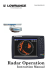
Pub. 988-0161-10B
Radar Operation
Instruction Manual
Copyright © 2008 Navico.
All rights reserved.
No part of this manual may be copied, reproduced, republished, transmitted or distributed for any purpose, without prior written consent of
Navico. Any unauthorized commercial distribution of this manual is strictly prohibited.
Lowrance® is a registered trademark of Navico. NMEA 2000® is a registered trademark of the National Marine Electronics Association.
Navico may find it necessary to change or end our policies, regulations
and special offers at any time. We reserve the right to do so without notice. All features and specifications subject to change without notice. This
manual covers all display units compatible with Lowrance Radar at
press time.
For free owner's manuals and the most current information on
this product, its operation and accessories,
visit our web site:
www.lowrance.com
Navico
12000 E. Skelly Dr.
Tulsa, OK USA 74128-2486
Printed in USA.
Table of Contents
Warnings and Cautions .......................................................... iii
Section 1: Introduction............................................................. 1
Software Update............................................................................ 1
Checking Software Version....................................................... 1
To download software update to MMC/SD card: ................. 1
To update display unit software: .......................................... 2
How to use this manual: typographical conventions .................. 2
Basic Radar Display Components ................................................ 3
Section 2: Radar Setup ............................................................. 5
Getting Started.............................................................................. 5
To access Radar Page: ........................................................... 6
Auto Power-On .............................................................................. 7
Turning on/off Auto Power-On: ............................................ 7
Radar Setup ................................................................................... 7
Trigger Delay Preparation........................................................ 8
Range...................................................................................... 8
Gain ........................................................................................ 8
Anti-Sea Clutter .................................................................... 8
Anti-Rain Clutter .................................................................. 8
Trigger Delay ......................................................................... 8
Adjust Trigger Delay................................................................. 9
Adjust Heading Line ............................................................... 10
Adjust Tune ............................................................................. 11
Section 3: Basic Operation .................................................... 13
Pages ............................................................................................ 13
Radar Only............................................................................... 13
Digital Data ............................................................................. 13
Radar with Map....................................................................... 13
Radar with Sonar .................................................................... 14
Radar with Gauges.................................................................. 14
Radar, Map and Sonar ............................................................ 15
Radar Menu ................................................................................. 15
Gain .......................................................................................... 15
Anti-Sea Clutter (STC)............................................................ 16
Anti-Rain Clutter (FTC).......................................................... 16
Interference Rejection ............................................................. 17
Radar Range ............................................................................ 17
Radar Echo Expansion............................................................ 18
Echo Trail Interval .................................................................. 18
Clear Radar Trails................................................................... 18
To clear radar trails: ........................................................... 18
i
Log Radar Data ....................................................................... 18
Radar Setup ............................................................................. 22
Radar Orientation ................................................................... 22
Radar Color Scheme................................................................ 22
Adjust Antenna Park .............................................................. 22
Radar Information................................................................... 23
Radar Power ............................................................................ 24
Turns the radar on and off...................................................... 24
Radar Simulator ...................................................................... 24
Radar Overlay ............................................................................. 25
Radar Options menu ............................................................... 25
Overlay Options menu ............................................................ 26
Section 4: Advanced Operation ............................................ 27
Reading the Display .................................................................... 27
Gain .......................................................................................... 27
Range Rings ............................................................................. 27
Anti-Sea Clutter (STC)............................................................ 28
Anti-Rain Clutter (FTC).......................................................... 28
Electronic Bearing Line (EBL) ............................................... 28
Variable Range Markers ......................................................... 28
Radar Cursor ........................................................................... 28
Appendix I: Glossary............................................................... 33
ii
Warnings and Cautions
Caution:
Use this radar at your own risk. This radar was designed for
use as a navigation aid. It should not be used for purposes that
require precise measurements of direction, distance, topography
or location. Always compare the navigation information received
from your radar with data from other navigation aids and
sources. When a conflict arises between the navigation data from
your radar and data from other navigation aids, make sure you
resolve the conflict before proceeding with navigation. A CAREFUL NAVIGATOR NEVER RELIES ON ONLY ONE
METHOD TO OBTAIN NAVIGATION INFORMATION.
Caution:
International Regulations for Preventing Collisions at Sea mandate that when radar is on a vessel, the radar must be used at
all times, regardless of weather conditions or visibility. Numerous court decisions have not only ruled the radar must be used,
but that the radar operator must be knowledgeable in all operational aspects of radar performance or otherwise face a greater
risk of liability if an accident occurs.
Caution:
If you purchased an open array radar antenna, make sure it is
installed in an area free of hardware obstructions and free of potential obstructions like sails, lines or other vessel components
that could intermittently intrude or be caught up in the array
antenna's rotation path.
WARNING: High Voltage Hazard
Dangerously high voltages are present within the radar
scanner unit. Technicians must exercise extreme care
when working inside the unit. ALWAYS remove power
before removing the cover. Some capacitors may take
several minutes to discharge, even after switching off
the radar. Before touching the magnetron or any high
voltage components, ground them with a clip lead.
iii
WARNING: Microwave Radiation Hazard
The microwave energy radiated by a radar antenna is
harmful to humans, especially to the eyes. NEVER look
directly into an open waveguide or into the path of radiation from an enclosed antenna. Radar and other radio frequency radiation can upset cardiac pacemakers.
If someone with a cardiac pacemaker suspects abnormal
operation, immediately turn off the radar equipment
and move the person away from the antenna. Turn off
the radar whenever it is necessary to work on the antenna unit or other equipment in the beam of the radar.
WARNING: Turn Off Radar When Docked
The radar beam can be harmful to humans in close proximity (within 20 yards, or 18.3 meters). When docked, be
considerate of other boats and pedestrians nearby and
remember to turn off your radar. If your boat is in a covered marina and the radar is on, a metal roof can act as
a reflector, bouncing microwave energy back at your
boat and passengers.
iv
Section 1: Introduction
Your radar consists of four components: the radar scanner unit (antenna),
your display unit (sold separately) radar processor and RIM 300 radar
interface module. This manual covers LRA-1800 and LRA-2400 radars.
WARNING:
Radar radiation can be harmful to you and bystanders.
Radar misuse or misunderstanding radar operation
could lead to a collision, which could result in property
damage, personal injury or death.
You must be familiar with the procedures and all warnings and cautions described in the installation and operation manuals in order to operate your radar safely
and effectively.
The following units are compatible with LRA-1800 and LRA2400 radars: LCX-113c HD, GlobalMap 9300c HD, LCX-112c, GlobalMap 9200, LCX-38c, GlobalMap 8300c, LCX-37c, GlobalMap 8200c,
GlobalMap Baja 840c, LCX-28c HD, GlobalMap 7300c HD, LCX-27c,
GlobalMap 7200c, LMS-520c, LMS-522c iGPS, LMS-522c iGPS IceMachine, LMS-525c DF, LMS-527c DF iGPS, Globalmap 5200c,
Globalmap 5300c iGPS, Globalmap Baja 540c, X510c and X515c DF.
Note for GlobalMap users: Menus and commands in your unit are
very similar to those shown in this manual, except your display will not
have sonar page, sonar alarm or sonar simulator options.
Software Update
If your display unit's software version is less than 2.2.0, you will need
to update the unit's software. To update your unit, contact your dealer
or download the update from our web site, www.lowrance.com.
Checking Software Version
1. With the display unit turned on, press MENU twice, use the arrow
keys to highlight SYSTEM SETUP and press ENTER.
2. Use the arrow keys to select SOFTWARE INFORMATION and press ENTER.
The software information screen will appear. If the version of software
listed on the software information screen is less than 2.2.0 you need to
update your display unit.
To download software update to MMC/SD card:
1. Log onto www.lowrance.com. Click on the PRODUCTS tab.
2. Select MARINE and then click on your display unit's category.
1
3. Select your display unit icon and choose DOWNLOADS. Click on the
DOWNLOAD button next to the desired software update.
4. Follow the onscreen installation instructions to download the update
onto your MMC/SD card.
To update display unit software:
1. With the display unit turned off, install the MMC or SD card that
contains the radar software update.
2. Turn on the unit and the update will install automatically.
3. When the update is finished, the unit will power up normally. After
the update is complete, remove the update MMC from the card slot.
The update program will be erased automatically when the process is
complete. You can now use this card to record sonar logs or GPS data.
NOTE:
Lowrance continues to regularly develop display enhancements and
new radar features. We recommend you periodically check our
web site for the latest free radar software updates.
How to use this manual: typographical conventions
Arrow Keys
The arrow keys are represented by symbols (↓ ↑ ← →).
Keyboard
When a key needs to be pressed, the key is shown in bold. For example,
the "Enter/Icons" key is shown as ENT and the "Menu" key is shown as
MENU.
Menu Commands
A menu command or a menu option will appear in small capital letters, in
a bold sans serif type like this: ROUTE PLANNING.
Instructions = Menu Sequences
Instructions for accessing the My Trails menu would look like this:
1. From the Map Page, press MENU|MENU|↓ ↑ to MY TRAILS|ENT.
Step 1 (above) means: "From the Map Page, press the Menu key twice.
Select (highlight) My Trails menu and press Enter."
2
Basic Radar Display Components
Range
Range Ring Interval
Anti-Sea
Clutter
Display
mode
Gain level
Interference
Rejection
status
Anti-Rain
Clutter
Radar
Cursor Boxes
Echo Trail
status
Radar Echo
Expansion
status
Electronic
Bearing
Lines
Variable
Range
Markers
Your unit has three electronic bearing
lines and three variable range markers.
An enlarged example of EBLs and
VRMs is on the next page.
Variable Range Marker position
for VRMs 1, 2 and 3. Highlighted
in white, VRM 2 is the active
range marker.
Electronic Bearing Line position
for EBLs 1, 2 and 3. Highlighted
in white, EBL 2 is the active bearing line.
3
PPI (radar screen's 360º
overhead view of the area)
Heading line (in green)
EBL2
EBL3
EBL1
VRM1
VRM2
VRM3
Bearings, in degrees
(in Heading Up mode,
relative to bow)
VRMs and EBLs allow you to track the distance and bearing
of multiple radar targets.
4
Section 2: Radar Setup
Before you begin radar setup, the radar scanning unit, RIM 300 module, radar processor and display unit all must be installed.
WARNING:
Do NOT attempt to execute Radar Setup, while the vessel is moving. Some motion from wind and wave action is
acceptable, but these setup instructions are NOT intended for vessels moving across the water.
Caution:
If you are unsure or do not understand the following instructions, it is strongly recommended that an experienced radar
technician handle radar setup and the installation of radar
hardware.
Getting Started
1. Press MENU|MENU, then use ↑ ↓ to SYSTEM SETUP and press ENT.
2. Highlight COMMUNICATIONS PORT and press ENT.
3. Press ↓ to RADAR and press ENT, which will place an X in the radar
checkbox. The Baud Rate automatically will switch to 230400 and a
Radar Notice will appear.
Communications Port menu (left). Radar Notice (right) prompting users to leave radar in Standby Mode for 30 minutes when activating radar for the first time.
Caution:
Leave the radar in Standby Mode for 30 minutes when activating it the first time. This will help maximize the life of the magnetron. After the radar has been activated the first time, ignore
the Radar Notice.
5
To access Radar Page:
1. Press PAGES, then use ← → to select the radar tab.
2. Press ↓ to select RADAR ONLY then press EXIT.
Radar only highlighted on Radar Pages menu (left). Radar menu with
Radar Power selected (right).
3. Press MENU, then use ↑ ↓ to select RADAR POWER from the radar menu
and press ENT. A confirmation message will appear. Press ← to select
YES and press ENT. A warm-up countdown will commence that will vary
depending on the model of radar you have.
4. After the countdown is finished, the unit will enter STANDBY mode.
5. Access the Radar Setup menu to make sure your radar display is set
to Heading Up and is set to a Full Color scheme. Press MENU, select
RADAR SETUP and press ENT.
Radar Setup selected from Radar menu (left). Radar Setup menu with
Full Color on Black highlighted (right).
6. To set the radar to Heading Up, highlight HEADING UP and press ENT.
7. To display the radar images in full color, press ↓ to select RADAR
COLOR SCHEME and press ENT.
6
8. Use ↑ ↓ to highlight one of the three full color options and press ENT.
Press EXIT to return to the main page display.
Auto Power-On
When the Auto Power-on feature is turned on, the radar will start
warming up every time the display unit is turned on. Access the Communications Port menu to turn on or turn off the Auto Power-on feature.
Caution:
If you do not plan to use your radar every time the display unit
is turned on, you need to turn off the Auto Power-On feature.
Turning on/off Auto Power-On:
1. From the Radar Page, press MENU, select RADAR SETUP and press ENT.
2. Highlight RADAR AUTO POWER ON and press ENT, which will check (turn
on) or uncheck (turn off) the radar checkbox. Auto Power-On is active
when there is an "X" in the Radar Auto Power On checkbox.
3. Press EXIT to return to the main radar display.
Communications Port menu with Auto Power-On feature turned on.
Radar Setup
The Radar Setup menu allows you to set up and adjust radar settings.
Most of the settings in the Radar Setup menu will only have to be set
once, but we recommend you check the settings periodically for general
maintenance.
NOTE:
Before starting radar setup, take your vessel out on open water
with fairly calm seas, like an open bay.
The two setup features we want to modify are Adjust Trigger Delay and
Adjust Heading Line.
7
We will set them up in that order, but before making any adjustments,
make sure the display is set to a range of 0.125 nautical miles and that
Gain, Anti-Sea Clutter (STC), Anti-Rain Clutter (FTC) and Trigger Delay all have been set to zero percent.
Trigger Delay Preparation
Range
1. To reset range to 0.125 nm, make sure you are on the Radar Only
page and press MENU.
2. Use ↑ ↓ to select RADAR RANGE and press ENT, which will call up the
Radar Range list. Press ↑ to select 0.125 nm and press ENT. You also
can set the range to 0.125 nm from the radar screen by using the ZIN
and ZOUT keys.
Gain
1. To set Gain to zero, press MENU, select GAIN and press ENT.
2. Press ↓ until the Gain is set to zero percent. Press EXIT. (Notice the
corresponding value in the upper right-hand corner of the screen.)
NOTE:
When adjusting Gain back to a useable level, increase the level until you see a light peppering on the display. Also remember, you will
have to adjust gain every time you change ranges.
Anti-Sea Clutter
1. To set Anti-Sea Clutter to zero, press MENU, select ANTI-SEA CLUTTER
(STC) and press ENT.
2. Press ↓ until the Anti-Sea Clutter is set to zero percent. Press EXIT.
(Notice the corresponding value in the upper right-hand corner of the
screen.)
Anti-Rain Clutter
1. To set Anti-Rain Clutter to zero, press MENU, select ANTI-RAIN CLUTTER
(FTC) and press ENT.
2. Press ↓ until the Anti-Rain Clutter is set to zero percent. Press EXIT.
(Notice the corresponding value in the upper right-hand corner of the
screen.)
Trigger Delay
1. To set Trigger Delay to zero, press MENU, select RADAR SETUP and
press ENT.
8
2. Press →|↓ to ADJUST TRIGGER DELAY and press ENT. That will launch
the Adjust Trigger Delay vertical scrollbar.
3. Press ↓ until Trigger Delay is set to zero percent. Press EXIT.
Adjust Trigger Delay
This feature eliminates the time lag between real radar returns and the
time it takes data to be processed by the radar software, a common issue with all radars.
Caution:
If you have any doubt about your understanding of the Trigger
Delay feature, you should have it set up by a qualified radar
technician.
1. The radar should already be in STANDBY mode, so press PWR for 2
seconds to switch the radar into transmission mode. A confirmation
message will appear, press ← to select YES.
2. Press MENU, select GAIN and press ENT. Press ↑ to increase the Gain
level to around 15%. One or two red rings with blue borders should be
visible on the screen, depending on the wattage of your radar antenna.
3. Press →|↓ to ADJUST TRIGGER DELAY, then press ENT.
The 2 kW model, the LRA-1800, will have only one ring on the display.
The 4 kW model, the LRA-2400, will have two rings on the display. See
the following figures.
Before adjusting the Trigger Delay for 4 kW radars, two rings will be
shown on the screen (left). As Trigger Delay is increased, the larger
ring will start to get smaller. The small ring will disappear (right).
You may have to increase gain in the previous step if the rings are not
visible. Increase gain until you have solid red rings shown on the
screen, like in the preceding example. Increasing Gain too much can
cause the rings to be distorted.
9
4. Press ↑ to increase the level of Trigger Delay, which will decrease the
size of the ring. If you have a 4 kW radar, as the large ring decreases in
size, the smaller ring in the center of the screen will disappear, leaving
only one ring.
Increase Trigger Delay to diminish the size of the red ring (left). To set
Trigger Delay correctly, reduce the ring to as small a size as possible,
while keeping a black circle in the middle (enlarged view, right).
In either case, continue to increase the Trigger Delay level until the
ring is as small as possible, while keeping a black circle in the middle.
Every radar is different, but typically, a setting between 35 and 42 percent will get the job done.
If you over apply the Trigger Delay, the black circle will disappear. Decrease the Trigger Delay level and it will reappear.
3. Press EXIT to return to the main page display.
Adjust Heading Line
The Heading Line command is used to make sure the green heading
line (zero point) on your display is lined up with the bow of your vessel.
(Before heading line adjustment)
(After heading line adjustment)
The bow of the ship is lined up with the tip of the peninsula (left), but the
green heading line is not. Adjusting the heading line will allow you to align
the direction of the heading line with the direction of the bow (right).
10
1. Line up the bow of your vessel with a point of reference, like a peninsula, lighthouse or other stationary target.
2. Press MENU, highlight RADAR SETUP and press ENT. Press → to select
ADJUST HEADING LINE and press ENT. That will place an arrow on each side
of the green Heading Line.
3. Use ← → to adjust the position of the green heading line, so its line
to the reference point's radar image matches your bow's actual line to
the reference point.
4. Press EXIT to remove the heading line arrows from the display.
Adjust Tune
Tuning should require no adjustment during the life of the unit. We
strongly recommend you do NOT adjust Tune settings yourself.
This feature is intended for use only by trained technicians. If for some
reason you need to use this function, consult your dealer or customer
service about the software updates necessary for tuning.
11
Notes
12
Section 3: Basic Operation
Pages
The Radar Page has six display options: Radar Only, Digital Data, Radar with Map, Radar with Sonar, Radar with Gauges and Radar, Map
and Sonar. GPS only units do not support the Radar with Sonar page,
so they have four display options: Radar Only, Digital Data, Radar with
Map and Radar with Gauges.
Radar Page Menu with Radar Only selected.
To access Radar page display options:
1. Press PAGES, then use ← → to highlight the radar tab.
2. Use ↑ ↓ to select the desired radar page configuration.
3. Press EXIT when the desired display option is highlighted.
Radar Only
Choose Radar Only if you want to display the radar full screen.
Digital Data
The Digital Data page allows you to customize digital data boxes with
information you want to monitor while viewing the radar display.
Radar with Map
To keep an eye on radar and GPS data at the same time, select Radar
with Map.
13
Digital Data page (left) with Radar with Map display (right).
NOTE:
When more than one page display is on the screen at the same
time, press PAGES|PAGES to switch the Active status between
windows. The title bar at the top of the window will be blue when
the window is active. The only exception is the map page, which
will display "Active Map" at the top of the map.
Radar with Sonar
The Radar with Sonar option allows you to monitor radar information,
while viewing sonar returns. Not available on GPS only units.
Radar with Sonar option (left). Radar with Gauges display (right).
Radar with Gauges
The Radar with Gauges display will split the screen between the radar
page and the gauge page. The gauge page can be customized to display
sonar and GPS information in digital and analog gauge formats.
NOTE:
For instructions on customizing the gauges window with digital information or analog gauges, refer to the overlay data entry in your
unit's instruction manual.
14
Radar, Map and Sonar page display.
Radar, Map and Sonar
The Radar, Map and Sonar page is broken up into three windows, allowing you to monitor the radar, map and sonar simultaneously.
Radar Menu
When a radar page is the active page, you can access the radar menu by
pressing MENU. To access the main menu, press MENU|MENU.
Radar Menu.
Gain
The Gain feature allows you to adjust the sensitivity of the receiver.
Setting Gain to a low level will clear up some of the clutter on the
screen, but also could eliminate some desired echoes. A high level of the
Gain, allows you to see greater detail around you, but will display more
clutter on the screen.
15
NOTE:
When adjusting Gain back to a useable level, increase the level until you see a light peppering of echoes on the display. Also remember, you will have to adjust gain every time you change ranges.
To adjust Gain:
1. Press PAGES, select the Radar tab and press ENT.
2. Press MENU, highlight GAIN and press ENT.
3. Use ↑ ↓ to adjust the Gain to a desired level. Press EXIT.
Gain vertical scrollbar (left) with Anti-Sea Clutter scrollbar (right).
Anti-Sea Clutter (STC)
The Anti-Sea Clutter feature lowers receiver sensitivity at shorter
ranges to reduce or eliminate echoes that reflect back at the antenna
due to wave action close to the vessel.
Caution
Increasing STC may reduce or eliminate weak echoes, like small
vessels. Use only the minimum amount needed, then check back
periodically to see if the STC level may be decreased.
To adjust Anti-Sea Clutter:
1. Press MENU, select ANTI-SEA CLUTTER and press ENT.
2. Use ↑ ↓ to adjust Anti-Sea Clutter to a desired level. Press EXIT.
Anti-Rain Clutter (FTC)
The Anti-Rain Clutter feature is used to reduce or eliminate massive
numbers of small echoes that clutter the display during rain or snow
storms.
To adjust Anti-Rain Clutter:
1. Press MENU, highlight ANTI-RAIN CLUTTER and press ENT.
2. Use ↑ ↓ to adjust the Anti-Rain Clutter setting to a desired level.
16
WARNING:
Increasing FTC may reduce or eliminate weak echoes,
like those from small vessels. Use only the minimum
amount needed, then check back periodically to see if
the FTC level may be decreased.
Anti-Rain Clutter vertical scrollbar (left) with Interference Rejection
scrollbar (right).
Interference Rejection
This feature filters out signals from other radars close to your location.
To adjust Interference Rejection:
1. Press MENU, select INTERFERENCE REJECTION and press ENT.
2. Use ↑ ↓ to adjust the Interference Rejection. Press EXIT.
Radar Range selected (left). List of radar ranges (right).
Radar Range
This feature allows you to expand the area shown on the display unit,
allowing you to see distant targets. You also can decrease the range to
focus on targets closing in on you.
17
To adjust radar range:
1. Press MENU, select RADAR RANGE and press ENT.
2. Use ↑ ↓ to select the desired range and press ENT.
NOTE:
When switching radar ranges, you likely will need to adjust Gain,
STC and FTC settings to achieve optimum performance.
Tip:
You can also adjust radar range by pressing the ZIN or ZOUT keys.
Radar Echo Expansion
The Radar Echo Expansion feature will make weak signals more visible
on the display by lengthening radar echoes.
To turn Radar Echo Expansion On/Off:
1. Press MENU, highlight RADAR ECHO EXPANSION and press ENT to turn it
on (check) or turn it off (uncheck). Press EXIT.
Remember, when Echo Expansion is on, all signals on the display will
be enlarged, including clutter.
Echo Trail Interval
The Echo Trail Interval feature displays an on-screen history (trail) of
the movements of all radar targets.
To adjust Echo Trail Interval
1. Press MENU, select ECHO TRAIL INTERVAL and press ENT.
2. The Echo Trail Interval menu will display a series of intervals with
options ranging from Continuous to Off. Use ↑ ↓ to highlight the desired interval and press ENT. Press EXIT.
NOTE:
This feature is best used in open water or when your vessel is stationary and you are tracking a moving target. If Echo Trail Interval
is on and your vessel is moving, the display will be crowded with
trails for every target, including stationary targets, like lighthouses
and land.
Clear Radar Trails
This feature is used to clear radar trails created with the Echo Trail
Interval command.
To clear radar trails:
1. Press MENU, highlight CLEAR RADAR TRAILS and press ENT.
Log Radar Data
If your unit has a hard drive (LCX-28cHD, LCX-38cHD, LCX-113cHD
GlobalMap 6600cHD, GlobalMap 7300cHD GlobalMap 7600cHD,
18
GlobalMap 8300cHD and GlobalMap 9300cHD) the Log Radar Data
feature will be available on the Radar menu, allowing you to save radar
logs. Saving a radar log allows you to reuse the log in the unit's simulator.
If your unit does not have a hard drive you will not see the Log
Radar Data command on your Radar menu.
Log Radar Data menu.
To record a radar log:
1. Press MENU, select LOG RADAR DATA and press ENT.
2. Press ENT to start logging.
The Chart Logging menu also allows you to change the file name or
browse through data files on your MMC or SD card.
To change the file name:
1. Press MENU, select LOG RADAR DATA and press ENT. Press ↓ to File
Name and press ENT.
2. Press ↑ ↓ to change the first letter, then press → to move to the next
letter. Repeat these steps until the desired name has been entered.
Press ENT. Press EXIT.
To browse data files:
1. Press MENU, select LOG RADAR DATA and press ENT. Select BROWSE FILES
and press ENT.
2. Use ↑ ↓ to scroll through the available files. Press EXIT|EXIT.
When you select a file from the file browse menu, you can copy, delete,
play or stop playing a data file.
19
Browse Files selected from the Radar Chart Logging menu (left).
Browse Files menu (right).
To copy data files:
1. Press MENU, select LOG RADAR DATA and press ENT. Select BROWSE FILES
and press ENT.
2. Select the desired file and press ENT.
3. The File Information window will appear with three buttons, copy,
delete and either stop or play.
File Information window (left). The Copy To window (right).
NOTE:
Stop will only appear in the File Information menu if the file is in
use.
3. Select COPY to save the file to an MMC or SD card. Use ← → to select
your MMC or SD card and press ENT.
4. Use ↑ ↓ to highlight the COPY FROM dialog box. Select your unit's hard
drive as the Copy-From location and press ENT.
5. Highlight the COPY button and press ENT.
To delete a data file:
1. Press MENU, select LOG RADAR DATA and press ENT. Select BROWSE FILES
and press ENT.
20
2. Select the desired file from the Browse Files menu and press ENT.
3. Highlight DELETE from the File Information window and press ENT.
4. A confirmation message will appear. Press ← to YES and press ENT.
To stop or play a data file:
1. Press MENU, select LOG RADAR DATA and press ENT. Select BROWSE FILES
and press ENT.
1. Select the desired file from the Browse Files menu and press ENT.
2. If the file is currently in use, the STOP button will be on the menu.
Otherwise the PLAY button will be displayed.
Stop button highlighted in File Information window (left). Play button
selected in File Information window (right).
3. To stop playing the chart currently in use, highlight STOP and press
ENT. The play button will replace the stop button on the File Information window. Press EXIT.
4. To play the chart again, highlight PLAY and press ENT. Press EXIT.
The radar simulator will automatically be turned on if you play a chart
from the File Information menu.
To rename a data file:
1. Press MENU, select LOG RADAR DATA and press ENT. Select BROWSE FILES
and press ENT.
2. Select the desired file from the Browse Files menu and press ENT.
3. Highlight NAME at the top of the File Information menu and press
ENT.
4. Press ↑ ↓ to change the first letter, then press → to move to the next
letter. Repeat these steps until the desired name has been entered.
5. Press EXIT repeatedly.
21
Radar Setup
The Radar Setup menu allows you to set up and adjust basic radar settings, like Heading Line, Trigger Delay and Tune, all of which are addressed in the section on Radar Setup. You can also modify Radar Orientation, Radar Color Scheme and Antenna Park from the Radar Setup
menu.
Radar Orientation
The Radar Orientation feature, displays the orientation of your radar,
which by default is set to Heading Up.
To select radar orientation:
1. Press MENU, select RADAR SETUP and press ENT.
2. Select the desired orientation (Heading Up, North Up or Course Up)
and press ENT.
Radar Color Scheme
Your radar has eight color options: Full Color on Black, Full Color on
Gray, Full Color on White, Green on Black, Yellow on Black, Yellow on
Blue, Night Viewing and Green CRT.
When using full color mode on the radar display, the strongest targets
will be displayed in red, weaker targets will be shown in green and the
weakest returns will be colored blue.
Radar Setup selected on System Setup menu (left). Radar Color
Scheme highlighted on Radar Setup menu (right).
To adjust the Radar Color Scheme:
1. Press MENU, select RADAR SETUP and press ENT.
2. Press ↓ to RADAR COLOR SCHEME and press ENT.
3. Select the desired color scheme and press ENT. Press EXIT.
Adjust Antenna Park
This feature allows users to adjust their open array antenna so it will
come to a stop in a desired position.
22
Selecting Adjust Antenna Park will place a dialog box in the upper
right-hand corner of the screen. Use Arrow keys to adjust it.
NOTE:
There is no recommended setting for Antenna Park. Use the trial
and error method when adjusting antenna park. Repeat the process
until the antenna comes to a stop in the desired position.
To adjust Antenna Park:
1. Before adjusting Antenna Park, make sure your vessel is stationary.
From the Radar Page, press MENU, select RADAR SETUP and press ENT.
2. Press →|↓ to ADJUST ANTENNA PARK and press ENT. The Park Adjust
dialog box will appear in the upper right-hand corner of the screen.
3. Use ← → to input the desired setting.
4. Test your settings by putting the radar into STANDBY Mode. Observe the location where the antenna stops. Repeat the steps above until the desired location is achieved. Press EXIT.
You must not be moving when attempting to adjust Antenna Park settings. Your vessel must be stationary for the antenna to stop in the desired position. If you attempt to adjust Antenna Park while the vessel is
underway or if the antenna stops in the desired position and you begin
moving, the wind will move the antenna out of position.
Radar Information
Displays information about the radar, like radar model, radar status
and software information.
To access radar information:
1. Press MENU, highlight RADAR INFORMATION and press ENT. Press EXIT.
23
Radar Power
Turns the radar on and off.
To turn the radar on or off:
1. Press MENU, select RADAR POWER and press ENT.
2. A confirmation message will appear. Select YES and press EXIT.
Radar Simulator
Your unit has a simulator that allows you to get familiar with radar
operation before heading out on the water.
Simulators highlighted on the System Setup menu (left). Radar Simulator On selected on Radar Simulator menu (right). Notice the simulator has not been turned on, since the checkbox is unchecked.
To access the Radar Simulator:
1. Press MENU|MENU, use ↑ ↓ to highlight SYSTEM SETUP and press ENT.
2. Use ↑ ↓ to highlight SIMULATORS and press ENT.
3. Press ← → to scroll to the RADAR SIMULATOR tab. If you have only one
radar log or if you want to use the current radar log, press ↓ to highlight RADAR SIMULATOR ON and press ENT.
4. If you have more than one Radar log loaded on your MMC or SD card
and you want to switch logs, press ↓ to Log Used and press ENT. Use ↑ ↓
to select the desired radar log and press ENT.
5. Press ↑ to RADAR SIMULATOR ON and press ENT. Repeat these steps to
turn off the simulator. Press EXIT repeatedly.
NOTE:
You can turn on the GPS Simulator from the Radar Simulator
menu. Press ↓ to SIMULATE POSITION, then press ENT, which will check
the Simulate Position checkbox.
24
Radar Overlay
The Radar Overlay feature allows you to overlay radar data on any
map page as long as you have a valid GPS position and a NMEA 2000
heading sensor or compatible NMEA 0183 heading sensor.
NOTE:
You will need to purchase a SIMRAD heading sensor for the Radar
Overlay feature to work properly.
To use Radar Overlay:
1. Press PAGES, highlight the MAP tab and press ENT.
2. Press MENU, highlight ENABLE RADAR OVERLAY and press ENT|EXIT.
3. To turn off Radar Overlay, repeat Step 2.
Radar Options menu
The Radar Options menu allows you to access radar settings and commands from the Map page menu. You, however, will ONLY be able to
access the Radar Options menu when Radar Overlay has been enabled.
Radar Options menu.
To access Radar Options menu from Map page:
1. Press MENU, highlight ENABLE RADAR OVERLAY and press ENT.
25
2. Highlight RADAR OPTIONS and press ENT to access the Radar Options
menu. To use the features on the Radar Options menu, refer the Radar
Menu instructions covered earlier in this section.
Overlay Options menu
The Overlay Options menu allows you to turn on overlay transparency,
select a transparency level, and choose the color of the radar overlay.
Radar Overlay Options menu (left) Radar Overlay in use on Radar
with Map page.
To access Overlay Options menu:
1. Press MENU, highlight RADAR OPTIONS and press ENT.
2. Select OVERLAY OPTIONS and press ENT.
To Adjust Transparency level:
3. Highlight Transparency level, then use ← → to adjust the transparency level of the radar overlay to the desired setting.
To select Overlay Color:
4. Highlight OVERLAY COLOR and press ENT, which will open the Overlay
Color drop-down menu with the following options: Yellow, Red, Orange,
Green, Magenta and Black.
5. Use ↑ ↓ to select the desired color and press ENT. Press EXIT to return to the main display.
26
Section 4: Advanced Operation
Radar Only page display.
Reading the Display
The radar page displays digital information on the screen which covers,
Range Rings, Gain, Anti-Sea Clutter (STC), Anti-Rain Clutter (FTC)
and when active, Electronic Bearing Lines (EBL) and Variable Range
Markers (VRM).
Gain
The percentage listed next to Gain, displays the current Gain setting
for your radar display.
NOTE:
When adjusting Gain back to a useable level, increase the level until you see a light peppering on the display. You will have to adjust
gain every time you change ranges.
Range Rings
The Range Ring display in the upper left-hand corner of the radar display shows the current range ring setting. In the example above, Range
is .5 nautical miles. The Range Ring setting (the distance between each
ring) is .125 nautical miles.
27
Anti-Sea Clutter (STC)
The STC percentage displays the current Anti-Sea Clutter setting on
your radar screen.
Anti-Rain Clutter (FTC)
The FTC percentage displays the current Anti-Rain Clutter setting on
your radar screen.
Electronic Bearing Line (EBL)
A radial line that can be rotated 360°, the electronic bearing line is
used to monitor the bearing of a radar target in relation to your location.
The EBL and VRM selection menu appears in a small box on the left
side of the radar display (left). Once activated, the EBL and VRM dialog boxes appear in the bottom corners of the screen (right).
Variable Range Markers
A range ring used to measure the precise distance to a target, the variable range marker may be adjusted to measure any distance within the
radar's range.
Radar Cursor
The Radar cursor allows you to use the arrow keys to pinpoint the relative bearing (EBL) and range (VRM) to a target on the display. That
allows you to simultaneously align the EBL and VRM with a target to
get a quick fix on its bearing and range. The Radar Cursor also can be
used to set up each of your EBL/VRMs.
To set up an EBL/VRM with the Radar cursor:
1. From any radar page, press ↓ to launch the Radar Cursor boxes in
the top left-hand corner of the display. The Radar Cursor will appear in
the center of the display.
2. Use ↓ ↑ , ← → to move the cursor to the desired target.
28
Radar
Cursor
Boxes
Radar cursor
The Radar Cursor boxes are show in white in the top, left-hand corner.
The Radar Cursor is aligned with a target in the bottom-right portion
of the screen
3. Press ENT to launch the EBL/VRM menu. Use ↑ ↓ to select the desired EBL and VRM and press ENT twice. Press EXIT. The Radar Cursor
coordinates have been assigned to the EBL/VRM you selected. The EBL
and VRM coordinates will be listed in the bottom left and right-hand
corners of the display.
4. If you want to use more than one EBL/VRM at a time, repeat these
steps for each EBL/VRM you want to set up.
To manually set up an EBL and VRM:
1. Press ENT to launch the EBL/VRM menu. Select an EBL/VRM and
press ENT.
2. Press ↑ ↓ to increase or decrease the size of the circular VRM. To find
the distance to a radar target, increase the size of the VRM until it is
lined up with the target. Check the display in the bottom right-hand
corner to see your distance from the target in nautical miles.
3. To adjust the position of the EBL, press ← → to move the EBL
around the display. Line up the EBL with a radar target to determine
the target's relative bearing. Check the display in the lower left-hand
corner to see the target's relative bearing displayed digitally.
4. When the EBL/VRM is in the desired position, press ENT. Press EXIT.
Repeat these steps for each EBL/VRM you want to set up.
29
VRM (Variable
Range Marker)
Radar
Cursor
Boxes
Radar
cursor
EBL (Electronic
Bearing Line)
EBL
L
VRM
The Variable Range (VRM) shows the target is 0.219 nautical miles
away. The Electronic Bearing Line (EBL) displays the target's bearing
as 099.9ºR.
To reposition an EBL/VRM:
1. Press ENT to launch the EBL/VRM menu. Select the EBL/VRM you
would like to change and press ENT.
2. Press ↑ ↓ to increase or decrease the size of the circular VRM. To find
the distance to another radar target, increase the size of the VRM until
it is lined up with the target.
3. Press ← → to move the EBL around the display. Line up the EBL
with a radar target to determine another target's relative bearing.
4. If you have more than one EBL/VRM on the radar display, repeat
these steps to reposition each EBL/VRM on the display. Press EXIT to
close the EBL/VRM menu.
30
VRM (Variable
Range Marker)
Radar
Target
EBL (Electronic
Bearing Line)
This is a zoomed in view from the previous image, clearly showing the
radar target, Variable Range Marker and Electronic Bearing Line.
To remove an EBL/VRM from the display:
1. Press ENT to call up the EBL/VRM menu. Select the EBL/VRM you
want to remove and press ENT.
2. Press EXIT and the desired EBL/VRM will be removed from the
screen.
3. Repeat these steps to remove each EBL/VRM from the display.
31
VRM2
EBL2
EBL3
VRM3
VRM1
EBL1
When using multiple EBL/VRMs, the size of the dashes and the distance between dashes allows you to distinguish between the different
EBL/VRMs on the display.
32
Appendix I: Glossary
Anti-Rain Clutter (FTC): used to reduce or eliminate massive number of small echoes that clutter the display during rain or snow storms.
Anti-Sea Clutter (STC): lowers receiver sensitivity at shorter ranges
to reduce or eliminate sea clutter echoes, which are most prevalent
around the vessel.
Beam: focused rays of microwave energy
Beam width: measured in degrees, the width of a beam, both horizontally and vertically.
Clutter: undesirable echoes created by rain, snow, waves and other
intermittent causes.
Course Up: a stabilized display mode in which the current userselected course is represented at the top of the radar display. This display mode requires a heading sensor.
EBL (Electronic Bearing Line): A radial line that can be rotated
360º, the electronic bearing line is used to monitor the bearing of a radar target in relation to your location.
Echo: reflected radio frequency pulse picked up by radar. It is also another name for a target image detected on the radar display.
Echo trail: a history (trail) of the echoes for a particular radar target.
Gain: used to adjust the sensitivity of the receiver to increase or decrease the intensity of images on the display.
Ghost Echo: an undesirable image created when returns are reflected
off other structures.
Heading Flash: the green line on the radar display that shows the
direction you are heading.
Heading Line Adjustment: the Heading Line is used to make sure
the green heading line (zero point) on your radar display is lined up the
bow of your vessel.
Heading Up: when your heading is displayed at the top of the screen,
you are in Heading Up mode.
Interference Rejection: filters out signals from other radars close to
your location.
33
North Up: a stabilized display mode in which North is at the top of the
radar display. This display mode requires a heading sensor.
Offset EBL: an electronic bearing line originating from a location other
than the PPI sweep origin.
Open Array Antenna: a radar antenna which has an external rotating scanner.
PPI (Plan Position Indicator): The PPI provides a map-like representation of target echoes.
Radar Overlay: radar image data laid over an electronic chart. This
feature requires a GPS position fix and a heading sensor. Radar Overlay is available only on GPS units and Sonar-GPS combo units.
Radome: a single housing containing a radar antenna and transceiver.
Rain Clutter: undesirable echoes caused by rain or snow.
Range: distance to a particular target.
Range Rings: fixed rings on the radar display designed to show the
distance from the antenna.
Sea Clutter: undesirable returns caused by smaller waves and water
movement.
Standby: radar mode that follows warm-up and precedes the start of
transmission.
Sweep Origin: the origin of EBL and VRM, the sweep origin is located
at the center of the PPI.
Target: an item detected by radar.
Time Base: line that rotates around the radar display, updating images on the display.
Tuning: intermediate frequency adjustment that enhances the performance of the radar.
VRM (Variable Range Marker): a range ring used to measure the
precise distance to a target, the variable range marker may be adjusted
to measure any distance within the radar's range.
34
Notes
35
Notes
36
Notes
37
FCC Compliance
This device complies with Part 15 and Part 80 of the U.S. Federal Communications Commission (FCC) Rules. Operation is
subject to the following two conditions: (1) this device may not
cause harmful interference, and (2) this device must accept any
interference received, including interference that may cause undesired operation.
Changes or modifications not expressly approved by the manufacturer could void the user's authority to operate the equipment.
Note:
This equipment has been tested and found to comply with the
limits for a Class B digital device, pursuant to Part 15 and part
80 of the FCC Rules. These limits are designed to provide reasonable protection against harmful interference in a residential
installation. This equipment generates, uses and can radiate radio frequency energy and, if not installed and used in accordance
with the instructions, may cause harmful interference to radio
communications. However, there is no guarantee that interference will not occur in a particular installation. If this equipment
does cause harmful interference to radio or television reception,
which can be determined by turning the equipment off and on,
the user is encouraged to try to correct the interference by one or
more of the following measures:
•
Reorient or relocate the receiving antenna.
•
Increase the separation between the equipment and receiver.
•
Connect the equipment into an outlet on a circuit different
from that to which the receiver is connected.
•
Consult the factory customer service department for help.
38
NAVICO
FULL ONE-YEAR WARRANTY
"We," "our," or "us" refers to NAVICO, the manufacturer of this product. "You" or "your"
refers to the first person who purchases this product as a consumer item for personal,
family or household use.
We warrant this product against defects or malfunctions in materials and workmanship,
and against failure to conform to this product's written specifications, all for one (1) year
from the date of original purchase by you. WE MAKE NO OTHER EXPRESS WARRANTY OR REPRESENTATION OF ANY KIND WHATSOEVER CONCERNING THIS
PRODUCT. Your remedies under this warranty will be available so long as you can show
in a reasonable manner that any defect or malfunction in materials or workmanship, or
any non-conformity with the product's written specifications, occurred within one year
from the date of your original purchase, which must be substantiated by a dated sales
receipt or sales slip. Any such defect, malfunction, or non-conformity which occurs within
one year from your original purchase date will either be repaired without charge or be
replaced with a new product identical or reasonably equivalent to this product, at our
option, within a reasonable time after our receipt of the product. If such defect, malfunction, or non-conformity remains after a reasonable number of attempts to repair by us,
you may elect to obtain without charge a replacement of the product or a refund for the
product. THIS REPAIR, OR REPLACEMENT OR REFUND (AS JUST DESCRIBED) IS
THE EXCLUSIVE REMEDY AVAILABLE TO YOU AGAINST US FOR ANY DEFECT,
MALFUNCTION, OR NON-CONFORMITY CONCERNING THE PRODUCT OR FOR
ANY LOSS OR DAMAGE RESULTING FROM ANY OTHER CAUSE WHATSOEVER.
WE WILL NOT UNDER ANY CIRCUMSTANCES BE LIABLE TO ANYONE FOR ANY
SPECIAL, CONSEQUENTIAL, INCIDENTAL, OR OTHER INDIRECT DAMAGE OF
ANY KIND.
Some states do not allow the exclusion or limitation of incidental or consequential damages, so the above limitations or exclusions may not apply to you.
This warranty does NOT apply in the following circumstances: (1) when the product has
been serviced or repaired by anyone other than us; (2) when the product has been connected, installed, combined, altered, adjusted, or handled in a manner other than according to the instructions furnished with the product; (3) when any serial number has been
effaced, altered, or removed; or (4) when any defect, problem, loss, or damage has resulted
from any accident, misuse, negligence, or carelessness, or from any failure to provide
reasonable and necessary maintenance in accordance with the instructions of the owner's
manual for the product.
We reserve the right to make changes or improvements in our products from time to time
without incurring the obligation to install such improvements or changes on equipment
or items previously manufactured.
This warranty gives you specific legal rights and you may also have other rights which
may vary from state to state.
REMINDER: You must retain the sales slip or sales receipt proving the date of your
original purchase in case warranty service is ever required.
NAVICO
12000 E. SKELLY DRIVE, TULSA, OK 74128
(800) 324-1356
39
How to Obtain Service…
…in the USA:
We back your investment in quality products with quick, expert service
and genuine Lowrance parts. If you're in the United States and you
have technical, return or repair questions, please contact the Factory
Customer Service Department. Before any product can be returned, you
must call customer service to determine if a return is necessary. Many
times, customer service can resolve your problem over the phone without sending your product to the factory. To call us, use the following
toll-free number:
800-324-1356
8 a.m. to 5 p.m. Central Standard Time, M-F
Lowrance Electronics may find it necessary to change or end our shipping policies, regulations, and special offers at any time. We reserve the
right to do so without notice.
…in Canada:
If you're in Canada and you have technical, return or repair questions,
please contact the Factory Customer Service Department. Before any
product can be returned, you must call customer service to determine if
a return is necessary. Many times, customer service can resolve your
problem over the phone without sending your product to the factory. To
call us, use the following toll-free number:
800-661-3983
905-629-1614 (not toll-free)
8 a.m. to 5 p.m. Eastern Standard Time, M-F
…outside Canada and the USA:
If you have technical, return or repair questions, contact the dealer in
the country where you purchased your unit. To locate a dealer near
you, visit our web site, www.lowrance.com and look for the Dealer Locator.
40
Accessory Ordering Information
for all countries
To order Lowrance accessories for your unit, please contact:
1) Your local marine dealer or consumer electronics store. Most quality
dealers that handle marine electronic equipment or other consumer
electronics should be able to assist you with these items.
To locate a Lowrance dealer near you, visit our web site,
www.lowrance.com and look for the Dealer Locator. Or, you can consult
your telephone directory for listings.
2) U.S. customers: LEI Extras Inc., PO Box 129, Catoosa, OK 74015-0129
Call 1-800-324-0045 or visit our web site www.lei-extras.com.
3) Canadian customers can write:
Lowrance/Eagle Canada, 919 Matheson Blvd. E. Mississauga, Ontario
L4W2R7 or fax 905-629-3118.
Shipping Information
If it becomes necessary to send a product for repair or replacement, you
must first receive a return authorization number from Customer
Service. Products shipped without a return authorization will not be
accepted. When shipping, we recommend you do the following:
1. Please do not ship the knobs or mounting bracket with your unit.
2. If you are sending a check for repair, please place your check in an
envelope and tape it to the unit.
3. For proper testing, include a brief note with the product describing
the problem. Be sure to include your name, return shipping address
and a daytime telephone number. An e-mail address is optional but
useful.
4. Pack the unit in a suitable size box with packing material to prevent
any damage during shipping.
5. Write the Return Authorization (RA) number on the outside of the
box underneath your return address.
6. For your security, you may want to insure the package through your
shipping courier. Lowrance does not assume responsibility for goods
lost or damaged in transit.
Visit our web site:
Lowrance Pub. 988-0161-10B
Printed in USA 090808
© Copyright 2008
All Rights Reserved
Navico