1
View Safety Info
SVM129-B
OCTOBER, 2006
®
INVERTEC STT
TM
& STT II
TM
For use with machine code numbers:10151,10152,10153,10309,10381,10382,10383,11090,11091,11092,
11115,11116
Return to Master TOC
View Safety Info
View Safety Info
Safety Depends on You
Return to Master TOC
Return to Master TOC
RETURN TO MAIN MENU
Lincoln arc welding and cutting
equipment is designed and built
with safety in mind. However,
your overall safety can be
increased by proper installation .
. . and thoughtful operation on
your part. DO NOT INSTALL,
OPERATE OR REPAIR THIS
EQUIPMENT WITHOUT READING THIS MANUAL AND THE
SAFETY PRECAUTIONS CONTAINED THROUGHOUT. And,
most importantly, think before
you act and be careful.
View Safety Info
Return to Master TOC
SERVICE MANUAL
Copyright © 2006 Lincoln Global Inc.
• World's Leader in Welding and Cutting Products •
• Sales and Service through Subsidiaries and Distributors Worldwide •
Cleveland, Ohio 44117-1199 U.S.A. TEL: 1-888-935-3877 FAX: 216.486.1751 WEB SITE: www.lincolnelectric.com
Return to Master TOC
i
i
SAFETY
WARNING
CALIFORNIA PROPOSITION 65 WARNINGS
Diesel engine exhaust and some of its constituents
are known to the State of California to cause cancer, birth defects, and other reproductive harm.
The Above For Diesel Engines
The engine exhaust from this product contains
chemicals known to the State of California to cause
cancer, birth defects, or other reproductive harm.
The Above For Gasoline Engines
ARC WELDING CAN BE HAZARDOUS. PROTECT YOURSELF AND OTHERS FROM POSSIBLE SERIOUS INJURY OR DEATH.
KEEP CHILDREN AWAY. PACEMAKER WEARERS SHOULD CONSULT WITH THEIR DOCTOR BEFORE OPERATING.
Return to Master TOC
Return to Master TOC
Return to Master TOC
Read and understand the following safety highlights. For additional safety information, it is strongly recommended that you
purchase a copy of “Safety in Welding & Cutting - ANSI Standard Z49.1” from the American Welding Society, P.O. Box 351040,
Miami, Florida 33135 or CSA Standard W117.2-1974. A Free copy of “Arc Welding Safety” booklet E205 is available from the
Lincoln Electric Company, 22801 St. Clair Avenue, Cleveland, Ohio 44117-1199.
BE SURE THAT ALL INSTALLATION, OPERATION, MAINTENANCE AND REPAIR PROCEDURES ARE
PERFORMED ONLY BY QUALIFIED INDIVIDUALS.
FOR ENGINE
powered equipment.
1.h. To avoid scalding, do not remove the
radiator pressure cap when the engine is
hot.
1.a. Turn the engine off before troubleshooting and maintenance
work unless the maintenance work requires it to be running.
____________________________________________________
1.b. Operate engines in open, well-ventilated
areas or vent the engine exhaust fumes
outdoors.
____________________________________________________
1.c. Do not add the fuel near an open flame welding arc or when the engine is running. Stop
the engine and allow it to cool before refueling to prevent spilled fuel from vaporizing on
contact with hot engine parts and igniting. Do
not spill fuel when filling tank. If fuel is spilled,
wipe it up and do not start engine until fumes
have been eliminated.
____________________________________________________
1.d. Keep all equipment safety guards, covers and devices in position and in good repair.Keep hands, hair, clothing and tools
away from V-belts, gears, fans and all other moving parts
when starting, operating or repairing equipment.
____________________________________________________
1.e. In some cases it may be necessary to remove safety
guards to perform required maintenance. Remove
guards only when necessary and replace them when the
maintenance requiring their removal is complete.
Always use the greatest care when working near moving
parts.
___________________________________________________
1.f. Do not put your hands near the engine fan.
Do not attempt to override the governor or
idler by pushing on the throttle control rods
while the engine is running.
___________________________________________________
1.g. To prevent accidentally starting gasoline engines while
turning the engine or welding generator during maintenance
work, disconnect the spark plug wires, distributor cap or
magneto wire as appropriate.
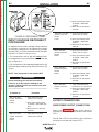
ELECTRIC AND
MAGNETIC FIELDS
may be dangerous
2.a. Electric current flowing through any conductor causes
localized Electric and Magnetic Fields (EMF). Welding
current creates EMF fields around welding cables and
welding machines
2.b. EMF fields may interfere with some pacemakers, and
welders having a pacemaker should consult their physician
before welding.
2.c. Exposure to EMF fields in welding may have other health
effects which are now not known.
2.d. All welders should use the following procedures in order to
minimize exposure to EMF fields from the welding circuit:
2.d.1. Route the electrode and work cables together - Secure
them with tape when possible.
2.d.2. Never coil the electrode lead around your body.
2.d.3. Do not place your body between the electrode and
work cables. If the electrode cable is on your right
side, the work cable should also be on your right side.
2.d.4. Connect the work cable to the workpiece as close as
possible to the area being welded.
2.d.5. Do not work next to welding power source.
Mar ‘95
Return to Master TOC
Return to Master TOC
ii
ELECTRIC SHOCK can kill.
ARC RAYS can burn.
3.a. The electrode and work (or ground) circuits
are electrically “hot” when the welder is on.
Do not touch these “hot” parts with your bare
skin or wet clothing. Wear dry, hole-free
gloves to insulate hands.
4.a. Use a shield with the proper filter and cover
plates to protect your eyes from sparks and
the rays of the arc when welding or observing
open arc welding. Headshield and filter lens
should conform to ANSI Z87. I standards.
3.b. Insulate yourself from work and ground using dry insulation.
Make certain the insulation is large enough to cover your full
area of physical contact with work and ground.
4.b. Use suitable clothing made from durable flame-resistant
material to protect your skin and that of your helpers from
the arc rays.
In addition to the normal safety precautions, if welding
must be performed under electrically hazardous
conditions (in damp locations or while wearing wet
clothing; on metal structures such as floors, gratings or
scaffolds; when in cramped positions such as sitting,
kneeling or lying, if there is a high risk of unavoidable or
accidental contact with the workpiece or ground) use
the following equipment:
• Semiautomatic DC Constant Voltage (Wire) Welder.
• DC Manual (Stick) Welder.
• AC Welder with Reduced Voltage Control.
4.c. Protect other nearby personnel with suitable, non-flammable
screening and/or warn them not to watch the arc nor expose
themselves to the arc rays or to hot spatter or metal.
3.c. In semiautomatic or automatic wire welding, the electrode,
electrode reel, welding head, nozzle or semiautomatic
welding gun are also electrically “hot”.
3.d. Always be sure the work cable makes a good electrical
connection with the metal being welded. The connection
should be as close as possible to the area being welded.
3.e. Ground the work or metal to be welded to a good electrical
(earth) ground.
3.f. Maintain the electrode holder, work clamp, welding cable and
welding machine in good, safe operating condition. Replace
damaged insulation.
Return to Master TOC
ii
SAFETY
3.g. Never dip the electrode in water for cooling.
3.h. Never simultaneously touch electrically “hot” parts of
electrode holders connected to two welders because voltage
between the two can be the total of the open circuit voltage
of both welders.
3.i. When working above floor level, use a safety belt to protect
yourself from a fall should you get a shock.
3.j. Also see Items 6.c. and 8.
FUMES AND GASES
can be dangerous.
5.a. Welding may produce fumes and gases
hazardous to health. Avoid breathing these
fumes and gases.When welding, keep
your head out of the fume. Use enough
ventilation and/or exhaust at the arc to keep
fumes and gases away from the breathing zone. When
welding with electrodes which require special
ventilation such as stainless or hard facing (see
instructions on container or MSDS) or on lead or
cadmium plated steel and other metals or coatings
which produce highly toxic fumes, keep exposure as
low as possible and below Threshold Limit Values (TLV)
using local exhaust or mechanical ventilation. In
confined spaces or in some circumstances, outdoors, a
respirator may be required. Additional precautions are
also required when welding on galvanized steel.
5. b. The operation of welding fume control equipment is affected
by various factors including proper use and positioning of the
equipment, maintenance of the equipment and the specific
welding procedure and application involved. Worker exposure level should be checked upon installation and periodically thereafter to be certain it is within applicable OSHA PEL
and ACGIH TLV limits.
5.c. Do not weld in locations near chlorinated hydrocarbon vapors
coming from degreasing, cleaning or spraying operations.
The heat and rays of the arc can react with solvent vapors to
form phosgene, a highly toxic gas, and other irritating products.
5.d. Shielding gases used for arc welding can displace air and
cause injury or death. Always use enough ventilation,
especially in confined areas, to insure breathing air is safe.
Return to Master TOC
5.e. Read and understand the manufacturer’s instructions for this
equipment and the consumables to be used, including the
material safety data sheet (MSDS) and follow your
employer’s safety practices. MSDS forms are available from
your welding distributor or from the manufacturer.
5.f. Also see item 1.b.
AUG 06
Return to Master TOC
iii
WELDING SPARKS can
cause fire or explosion.
6.a. Remove fire hazards from the welding area.
If this is not possible, cover them to prevent
the welding sparks from starting a fire.
Remember that welding sparks and hot
materials from welding can easily go through small cracks
and openings to adjacent areas. Avoid welding near
hydraulic lines. Have a fire extinguisher readily available.
6.b. Where compressed gases are to be used at the job site,
special precautions should be used to prevent hazardous
situations. Refer to “Safety in Welding and Cutting” (ANSI
Standard Z49.1) and the operating information for the
equipment being used.
Return to Master TOC
6.c. When not welding, make certain no part of the electrode
circuit is touching the work or ground. Accidental contact can
cause overheating and create a fire hazard.
6.d. Do not heat, cut or weld tanks, drums or containers until the
proper steps have been taken to insure that such procedures
will not cause flammable or toxic vapors from substances
inside. They can cause an explosion even though they have
been “cleaned”. For information, purchase “Recommended
Safe Practices for the Preparation for Welding and Cutting of
Containers and Piping That Have Held Hazardous
Substances”, AWS F4.1 from the American Welding Society
(see address above).
6.e. Vent hollow castings or containers before heating, cutting or
welding. They may explode.
6.f. Sparks and spatter are thrown from the welding arc. Wear oil
free protective garments such as leather gloves, heavy shirt,
cuffless trousers, high shoes and a cap over your hair. Wear
ear plugs when welding out of position or in confined places.
Always wear safety glasses with side shields when in a
welding area.
Return to Master TOC
iii
SAFETY
6.g. Connect the work cable to the work as close to the welding
area as practical. Work cables connected to the building
framework or other locations away from the welding area
increase the possibility of the welding current passing
through lifting chains, crane cables or other alternate circuits.
This can create fire hazards or overheat lifting chains or
cables until they fail.
6.h. Also see item 1.c.
CYLINDER may explode
if damaged.
7.a. Use only compressed gas cylinders
containing the correct shielding gas for the
process used and properly operating
regulators designed for the gas and
pressure used. All hoses, fittings, etc. should be suitable for
the application and maintained in good condition.
7.b. Always keep cylinders in an upright position securely
chained to an undercarriage or fixed support.
7.c. Cylinders should be located:
• Away from areas where they may be struck or subjected to
physical damage.
• A safe distance from arc welding or cutting operations and
any other source of heat, sparks, or flame.
7.d. Never allow the electrode, electrode holder or any other
electrically “hot” parts to touch a cylinder.
7.e. Keep your head and face away from the cylinder valve outlet
when opening the cylinder valve.
7.f. Valve protection caps should always be in place and hand
tight except when the cylinder is in use or connected for
use.
7.g. Read and follow the instructions on compressed gas
cylinders, associated equipment, and CGA publication P-l,
“Precautions for Safe Handling of Compressed Gases in
Cylinders,” available from the Compressed Gas Association
1235 Jefferson Davis Highway, Arlington, VA 22202.
FOR ELECTRICALLY
powered equipment.
8.a. Turn off input power using the disconnect
switch at the fuse box before working on
the equipment.
8.b. Install equipment in accordance with the U.S. National
Electrical Code, all local codes and the manufacturer’s
recommendations.
8.c. Ground the equipment in accordance with the U.S. National
Electrical Code and the manufacturer’s recommendations.
Return to Master TOC
Mar ‘95
Return to Master TOC
Return to Master TOC
Return to Master TOC
Return to Master TOC
iv
iv
SAFETY
PRÉCAUTIONS DE SÛRETÉ
Pour votre propre protection lire et observer toutes les instructions
et les précautions de sûreté specifiques qui parraissent dans ce
manuel aussi bien que les précautions de sûreté générales suivantes:
Sûreté Pour Soudage A L’Arc
1. Protegez-vous contre la secousse électrique:
a. Les circuits à l’électrode et à la piéce sont sous tension
quand la machine à souder est en marche. Eviter toujours
tout contact entre les parties sous tension et la peau nue
ou les vétements mouillés. Porter des gants secs et sans
trous pour isoler les mains.
b. Faire trés attention de bien s’isoler de la masse quand on
soude dans des endroits humides, ou sur un plancher metallique ou des grilles metalliques, principalement dans
les positions assis ou couché pour lesquelles une grande
partie du corps peut être en contact avec la masse.
c. Maintenir le porte-électrode, la pince de masse, le câble de
soudage et la machine à souder en bon et sûr état defonctionnement.
d.Ne jamais plonger le porte-électrode dans l’eau pour le
refroidir.
e. Ne jamais toucher simultanément les parties sous tension
des porte-électrodes connectés à deux machines à souder
parce que la tension entre les deux pinces peut être le total
de la tension à vide des deux machines.
f. Si on utilise la machine à souder comme une source de
courant pour soudage semi-automatique, ces precautions
pour le porte-électrode s’applicuent aussi au pistolet de
soudage.
2. Dans le cas de travail au dessus du niveau du sol, se protéger
contre les chutes dans le cas ou on recoit un choc. Ne jamais
enrouler le câble-électrode autour de n’importe quelle partie du
corps.
3. Un coup d’arc peut être plus sévère qu’un coup de soliel, donc:
zones où l’on pique le laitier.
6. Eloigner les matériaux inflammables ou les recouvrir afin de
prévenir tout risque d’incendie dû aux étincelles.
7. Quand on ne soude pas, poser la pince à une endroit isolé de
la masse. Un court-circuit accidental peut provoquer un
échauffement et un risque d’incendie.
8. S’assurer que la masse est connectée le plus prés possible de
la zone de travail qu’il est pratique de le faire. Si on place la
masse sur la charpente de la construction ou d’autres endroits
éloignés de la zone de travail, on augmente le risque de voir
passer le courant de soudage par les chaines de levage,
câbles de grue, ou autres circuits. Cela peut provoquer des
risques d’incendie ou d’echauffement des chaines et des
câbles jusqu’à ce qu’ils se rompent.
9. Assurer une ventilation suffisante dans la zone de soudage.
Ceci est particuliérement important pour le soudage de tôles
galvanisées plombées, ou cadmiées ou tout autre métal qui
produit des fumeés toxiques.
10. Ne pas souder en présence de vapeurs de chlore provenant
d’opérations de dégraissage, nettoyage ou pistolage. La
chaleur ou les rayons de l’arc peuvent réagir avec les vapeurs
du solvant pour produire du phosgéne (gas fortement toxique)
ou autres produits irritants.
11. Pour obtenir de plus amples renseignements sur la sûreté, voir
le code “Code for safety in welding and cutting” CSA Standard
W 117.2-1974.
PRÉCAUTIONS DE SÛRETÉ POUR
LES MACHINES À SOUDER À
TRANSFORMATEUR ET À
REDRESSEUR
a. Utiliser un bon masque avec un verre filtrant approprié ainsi
qu’un verre blanc afin de se protéger les yeux du rayonnement de l’arc et des projections quand on soude ou
quand on regarde l’arc.
b. Porter des vêtements convenables afin de protéger la peau
de soudeur et des aides contre le rayonnement de l‘arc.
c. Protéger l’autre personnel travaillant à proximité au
soudage à l’aide d’écrans appropriés et non-inflammables.
1. Relier à la terre le chassis du poste conformement au code de
l’électricité et aux recommendations du fabricant. Le dispositif
de montage ou la piece à souder doit être branché à une
bonne mise à la terre.
4. Des gouttes de laitier en fusion sont émises de l’arc de
soudage. Se protéger avec des vêtements de protection libres
de l’huile, tels que les gants en cuir, chemise épaisse, pantalons sans revers, et chaussures montantes.
3. Avant de faires des travaux à l’interieur de poste, la debrancher à l’interrupteur à la boite de fusibles.
2. Autant que possible, I’installation et l’entretien du poste seront
effectués par un électricien qualifié.
4. Garder tous les couvercles et dispositifs de sûreté à leur place.
5. Toujours porter des lunettes de sécurité dans la zone de
soudage. Utiliser des lunettes avec écrans lateraux dans les
Mar. ‘93
v
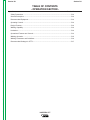
MASTER TABLE OF CONTENTS FOR ALL SECTIONS
RETURN TO MAIN MENU
Page
Safety .................................................................................................................................................i-iv
Installation.............................................................................................................................Section A
Operation...............................................................................................................................Section B
Accessories ..........................................................................................................................Section C
Maintenance ..........................................................................................................................Section D
Theory of Operation .............................................................................................................Section E
Troubleshooting and Repair ................................................................................................Section F
Electrical Diagrams ..............................................................................................................Section G
STT Parts .......................................................................................................................................P257
STT II Parts ....................................................................................................................................P294
INVERTEC STT
v
Return to Master TOC
Section A-1
TABLE OF CONTENTS
- INSTALLATION SECTION -
Section A-1
Installation .............................................................................................................................Section A
Technical Specifications (Codes 11092 & Below) .......................................................................A-2
Technical Specifications (Codes 11115 & 11116) ........................................................................A-3
Location.......................................................................................................................................A-4
Stacking.......................................................................................................................................A-4
Tilting...........................................................................................................................................A-4
Machine Grounding and High Frequency Interference Protection..............................................A-4
Input Connections .......................................................................................................................A-4
Supply Connections..............................................................................................................A-4
Ground Connection...............................................................................................................A-5
Input Voltage Reconnect Procedure ...........................................................................................A-6
Output Connections ....................................................................................................................A-6
Wire Feeder Output Connections .........................................................................................A-6
Return to Master TOC
Return to Master TOC
Return to Master TOC
Input Cable Installation and Connection...............................................................................A-5
INVERTEC STT
Return to Master TOC
Return to Section TOC
A-2
A-2
INSTALLATION
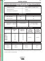
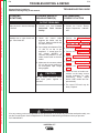
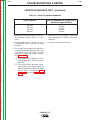
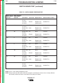
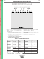
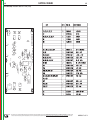
TECHNICAL SPECIFICATIONS –Invertec STT & STT II (For Codes 11092 and BELOW)
INPUT- THREE PHASE ONLY
STANDARD VOLTAGE
INPUT CURRENT AT RATED OUTPUT
208/230/460/3/60 HZ
32/30/16
200/220/380/415/440/3/50/60 HZ
33/30/18/17/16
Return to Master TOC
Return to Section TOC
RATED OUTPUT
DUTY CYCLE
AMPS
VOLTS AT RATED AMPS
60% Duty Cycle
225
29
100% Duty Cycle
200
28
OUTPUT
CURRENT RANGE
OPEN CIRCUIT VOLTAGE
Peak Current 1 0 - 450 Amps
Background
0 - 125 Amps
AUXILIARY POWER
85 VDC Maximum
115 2 VAC @ 4 Amps
42
VAC @ 4 Amps
RECOMMENDED INPUT WIRE AND FUSE SIZES
Return to Master TOC
Return to Master TOC
Return to Section TOC
Return to Section TOC
INPUT VOLTAGE
AND FREQUENCY
FUSE(SUPER LAG)
OR BREAKER
SIZE
INPUT AMPERE
RATING ON
NAMEPLATE
208/60
230/60
460/60
200/50/60
40
40
30
40
32
30
16
33
220/50/60
380/50/60
415/50/60
440/50/60
40
30
30
30
30
18
17
16
TYPE 75 C
COPPER
SUPPLY WIRE
IN CONDUIT
AWG (IEC) SIZES
10 (6 mm2)
TYPE 75 C
COPPER
GROUND WIRE
IN CONDUIT
AWG (IEC) SIZES
10 (6 mm2)
PHYSICAL DIMENSIONS
HEIGHT
WIDTH
DEPTH
WEIGHT
23.2 in
13.2 in.
24.4 in.
100 lbs.
589 mm
336 mm
620 mm
46 kg
1
At low input voltages (below 208 VAC) and input voltages of 380 VAC through 415 VAC there may be a 15% reduction in Peak Current.
2
115 VAC not present on European Models.
INVERTEC STT
Return to Master TOC
Return to Section TOC
A-3
A-3
INSTALLATION
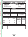
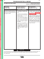
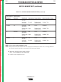
TECHNICAL SPECIFICATIONS –Invertec STT II (For Codes 11115 AND 11116)
INPUT- THREE PHASE ONLY
STANDARD VOLTAGE
INPUT CURRENT AT RATED OUTPUT
200/208/3/50/60 HZ
36/34
200/208/380/400/415/3/50/60 HZ
36/34/20/19/18
Return to Master TOC
Return to Section TOC
RATED OUTPUT
DUTY CYCLE
AMPS
VOLTS AT RATED AMPS
60% Duty Cycle
225
29
100% Duty Cycle
200
28
OUTPUT
CURRENT RANGE
OPEN CIRCUIT VOLTAGE
Peak Current 0 - 450 Amps
Background 0 - 125 Amps
AUXILIARY POWER
88 VDC Maximum
115 1 VAC @ 4 Amps
42
VAC @ 4 Amps
RECOMMENDED INPUT WIRE AND FUSE SIZES
Return to Master TOC
Return to Section TOC
INPUT VOLTAGE
AND FREQUENCY
Return to Master TOC
INPUT AMPERE
RATING ON
NAMEPLATE
200/50/60
208/50/60
40
40
36
34
380/50/60
400/50/60
415/50/60
30
30
30
20
19
18
TYPE 75 C
COPPER
SUPPLY WIRE
IN CONDUIT
AWG (IEC) SIZES
TYPE 75 C
COPPER
GROUND WIRE
IN CONDUIT
AWG (IEC) SIZES
10 (6 mm2)
10 (6 mm2)
PHYSICAL DIMENSIONS
1
Return to Section TOC
FUSE(SUPER LAG)
OR BREAKER
SIZE
HEIGHT
WIDTH
DEPTH
WEIGHT
23.2 in
13.2 in.
24.4 in.
100 lbs.
589 mm
336 mm
620 mm
46 kg
115 VAC not present on European Models.
INVERTEC STT
Return to Master TOC
Return to Section TOC
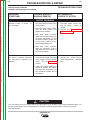
A-4
INSTALLATION
MACHINE GROUNDING AND HIGH
FREQUENCY INTERFERENCE
PROTECTION
Read and understand entire Installation
Section before starting installation.
WARNING
The machine may not be suitable for use in an environment where high frequency is present. For example do not place the machine in close proximity to “TIG”
or “PLASMA” operations. To minimize high frequency
interference:
ELECTRIC SHOCK can kill.
• Only qualified personnel should
perform this installation.
• Turn the input power OFF at the
disconnect switch or fuse box
before installing this
equipment.
Locate the STT II power source more than 15
feet (4.5 m) away from high frequency units
and more than 25 feet (7.6 m) separation
between ground connections or welding arcs
of high frequency units.
Return to Master TOC
Return to Master TOC
Return to Section TOC
Return to Section TOC
• Turn the power switch on the Invertec
STT “OFF” before connecting or disconnecting input power lines, output cables,
or control cables.
• Do not touch electrically hot
parts.
Return to Master TOC
Provide proper electrical ground to the
machine per local and national electrical
codes.
• Always connect the ground terminal to a
good electrical earth ground.
SELECT SUITABLE LOCATION
INPUT CONNECTIONS
Locate the machine where there is free circulation of
clean air. Place the machine so that air can freely circulate into the sides and out of the rear of the
machine. Dirt and dust that can be drawn into the
machine should be kept to a minimum. Failure to
observe these precautions can result in excessive
operating temperatures and nuisance shut down of the
Invertec STT II.
This machine carries an enclosure rating of IP21S. It
should not be placed in extremely damp or dirty locations. It should not be exposed to rain or snow.
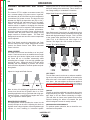
STACKING
FAILURE TO FOLLOW THESE INSTRUCTIONS
CAN CAUSE IMMEDIATE FAILURE OF COMPONENTS WITHIN THE WELDER.
Turn the input power off at the disconnect switch
before attempting to connect the input power lines.
Connect the green lead of the power cord to ground
per local and national electrical codes.
SUPPLY CONNECTIONS
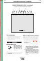
Be sure the voltage, phase, and frequency of the input
supply is as specified on the rating plate. Input Power
supply line entry in provided on the case back of the
machine. See figure A.1 for location of the rating plate.
The Invertec STT II cannot be stacked.
TILTING
Place the machine on a secure, level surface otherwise
the unit may topple over.
Return to Section TOC
A-4
The Invertec STT II should be connected only by a
qualified electrician. Installation should be made in
accordance with local and national codes. Refer to the
“Technical Specifications” at the beginning of this
section for proper fuse sizes, ground wire, and input
supply power cable sizes.
Some models come from the factory with an input
power cord. If your model does not include the input
power cord install the proper size input cable and
ground cable according to “INPUT CABLE INSTALLATION AND CONNECTION”.
INVERTEC STT
Return to Section TOC
Return to Master TOC
Return to Section TOC
Return to Master TOC
A-5
INSTALLATION
A-5
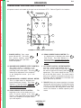
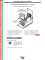
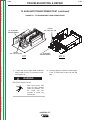
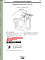
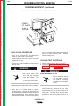
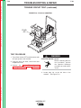
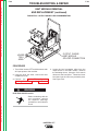
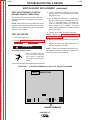
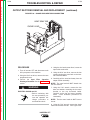
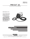
CASE BACK
RATING PLATE
INPUT CABLE
ENTRY ACCESS
& CABLE STRAIN RELIEF
FIGURE A.1 CASE BACK
Return to Master TOC
Return to Section TOC
INPUT CABLE INSTALLATION AND CONNECTION
A cable strain relief is provided at the supply line entry
and is designed to accommodate cable diameters of
.310 - 1.070 in. (7.9 - 27.2 mm). On European models
the strain relief is designed to accommodate cable
diameters of .709 - 1.000 in. (18.0 - 25.4 mm). Refer to
“Technical Specifications” at the beginning of this section for the proper input cable sizes. Refer to Figure A.1
and perform the following steps:
1.
Return to Master TOC
Return to Section TOC
2.
Remove the wraparound cover of the
Invertec STT II.
5. Connect the three phase line conductors to the power switch terminals labeled U, V and W. Tighten
the connections to 3.0 Nm. (27 in.-lb.) torque.
6.
Securely tighten the cable strain relief located
on the case back of the machine.
GROUND CONNECTION
1. Connect the ground terminal to earth
ground per National Electrical Code.
Feed the input cable through the input cable
entry access hole at the right rear of the
machine.
3.
Route the cable through the cable hangers,
located along the lower right inside edge of
the machine, up to the power switch located on
the front panel.
4.
Strip away 102 mm (4 in.) of the outer jacket.
Trim fillers and strip conductor jackets to
connect to the power switch.
2. Replace the wraparound cover of the
Invertec STT II.
INVERTEC STT
A-6
INSTALLATION
Return to Master TOC
Return to Section TOC
A-6
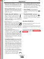
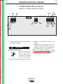
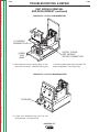
4A
380-415
OR
*
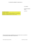
2. Move input voltage switch
to Voltage = 380-460V
position.
3. Move lead “A” to 380-415
Terminal.
*
OR
200-208
*(NOT PRESENT ON ALL MODELS)
Return to Master TOC
Return to Section TOC
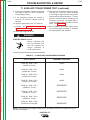
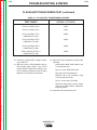
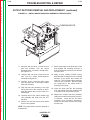
FIGURE A.2 RECONNECT PANEL
INPUT VOLTAGE RECONNECT
PROCEDURE
As shipped from the factory, multiple voltage machines
are internally configured for the highest input voltage
(440-460 VAC), for Codes 11092 and below and (380415 VAC), for Codes 11115 and 11116.
1. For Connections to 440 or 460 VAC verify the internal configurations to the procedures shown below and
refer to Figure A.2.
Return to Master TOC
Return to Section TOC
2. For Connections to 200,208,220,230,380,400 or 415
VAC follow the procedure shown below and refer to figure A.2.
NOTE: Turn main power to the machine OFF
before performing the reconnect procedure.
Failure to do so will result in damage to the
machine. DO NOT switch the reconnect bar with
machine power ON.
------------------------------------------------------------------------
460 or 440 VAC
(Codes 11092 and
around.
below)
Return to Master TOC
1. Open reconnect panel
access door on wrap-
220 or 230 VAC
(Codes 11092 and
around.
below)
1. Open reconnect panel
access door on wrap-
200 or 208 VAC
(Codes 11092 and
around.
below)
1. Open reconnect panel
access door on wrap-
200 or 208 VAC
(Codes 11115 and
11116)
1. Open reconnect panel
access door on wrap-around.
2. Move input voltage switch
to Voltage = 200 -230V
position.
3. Move lead “A” to 200-208
Terminal.
WARNING
To Operate at
Return to Section TOC
380,400 or 415 VAC
(Codes 11115 and
around.
11116)
380 or 415 VAC
(Codes 11092 and
around.
below)
Procedure
1. Open reconnect panel
access door on wrap2. Move input voltage switch
to Voltage = 380 -460V position.
3. Move lead “A” to 440-460
Terminal.
1. Open reconnect panel
access door on wrap-
2. Move input voltage switch
to Voltage = 380-460V
position.
3. Move lead “A” to 380-415
Terminal.
2. Move input voltage switch
to Voltage = 200 -230V
position.
3. Move lead “A” to 220-230
Terminal.
2. Move input voltage switch
to Voltage = 200 -230V
position.
3. Move lead “A” to 200-208
Terminal.
OUTPUT CONNECTIONS
WIRE FEEDER OUTPUT CONNECTIONS
Refer to the Accessories section of this manual for
instructions on connecting a wire feeder to the Invertec
STT II.
The LN-742 or STT-10 wire feeder is the recommended feeder for use with the Invertec STT II.
INVERTEC STT II
Return to Master TOC
Section B-1
Section B-1
TABLE OF CONTENTS
- OPERATION SECTION Operation...............................................................................................................................Section B
Safety Precautions ......................................................................................................................B-2
General Description ....................................................................................................................B-3
Recommended Equipment..........................................................................................................B-3
Operating Controls ......................................................................................................................B-3
Design Features..........................................................................................................................B-3
Welding Capability ......................................................................................................................B-3
Limitations ...................................................................................................................................B-3
Welding Operation ......................................................................................................................B-5
Welding Parameters and Guidelines ..........................................................................................B-6
Recommended Settings for STT II..............................................................................................B-7
Return to Master TOC
Return to Master TOC
Return to Master TOC
Operational Features and Controls.............................................................................................B-4
INVERTEC STT
Return to Master TOC
Return to Section TOC
B-2
OPERATION
OPERATING INSTRUCTIONS
Read and understand entire section before
operating machine.
GENERAL WARNINGS
SAFETY PRECAUTIONS
WARNING
Return to Master TOC
Return to Section TOC
ELECTRIC SHOCK
can kill.
• Do not touch electrically live parts
or electrode with skin or wet
clothing.
• Insulate yourself from work and
ground.
• Always wear dry insulating
gloves.
FUMES AND GASES
can be dangerous.
Return to Master TOC
Return to Section TOC
• Keep your head out of fumes.
• Use ventilation or exhaust to
remove fumes from breathing
zone.
WELDING SPARKS
can cause fire or
explosion
• Keep flammable material away.
• Do not weld on containers that
have held combustibles.
ARC RAYS
can burn.
Return to Master TOC
Return to Section TOC
• Wear eye, ear and body
protection.
Observe additional Safety Guidelines detailed in the beginning of this manual.
INVERTEC STT
B-2
Return to Master TOC
Return to Master TOC
Return to Section TOC
Return to Section TOC
B-3
OPERATION
GENERAL DESCRIPTION
•
High temperature Class H insulation.
The Invertec STT II is a 225-ampere inverter based arc
welding power source specifically designed for the STT
welding process. It is neither a constant current (CC)
nor a constant voltage (CV) machine. It is a power
source that delivers current of a desired wave form and
characteristics that are superior to conventional short
circuiting GMAW. The process is optimized for shortcircuiting GMAW welding.
•
Protection circuits and ample safety margins prevent
damage to the solid state components from transient
voltages and high currents.
•
Preset welding current capability.
Return to Master TOC
Return to Master TOC
Return to Section TOC
• STT II offers improvements over the previous model.
Approximately 40% increase in deposition rate capability, and a significant increase in travel speed.
RECOMMENDED EQUIPMENT
WELDING CAPABILITY
The LN-742 or STT-10 wire feeder is recommended for
use with the STT II. The LN-7 GMA, LN-9 GMA, NA-5,
and NA-5R can all be used with the STT II. However,
these units can only be used to feed wire since these
feeders have no provision for control of the STT output.
The Invertec STT II is rated at 225 amps, 29 volts, at
60% duty cycle on a ten minute basis. It is capable of
higher duty cycles at lower output currents. If the duty
cycle(s) are exceeded, a thermal protector will shut off
the output until the machine cools to a reasonable
operating temperature.
OPERATING CONTROLS
LIMITATIONS
The Invertec STT II has the following controls as standard: On/Off switch, Peak Current adjustment,
Background Current adjustment, Hot Start adjustment,
Tailout, and 2 toggle switches; one for wire size selection and one for wire type selection.
DESIGN FEATURES AND ADVANTAGES
Return to Section TOC
B-3
•
State of the art inverter technology yields high power
efficiency, excellent welding performance, lightweight and compact design.
•
Twist-Mate™ output terminals.
•
Digital meters for procedure settings are standard.
•
Automatic Inductance or Pinch Control.
•
Solid state circuitry for extra long component life.
•
Current feedback ensures that original procedure
settings all remain constant.
•
Arc Sense lead assembly (Electrode and Work),
connects through a 4-pin case front connector.
•
Peak Current and Background Current may be
remotely controlled.
•
Thermostat and FET over current protector prevent
overheating from overloads, high ambient temperatures, or loss of air flow.
•
May not be suitable for use in an environment with
High Frequency present. (“See Machine Grounding
and High Frequency Protection” in the Installation
section of this manual)
•
Suitable for indoor use only (IEC IP21S).
INVERTEC STT
Return to Master TOC
Return to Section TOC
B-4
B-4
OPERATION
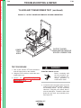
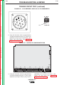
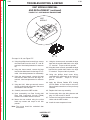
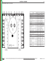
OPERATIONAL FEATURES AND CONTROLS
All operator controls are located on the case front of the Invertec STT II. Refer to Figure B.1 for locations.
4
5
6
7
2
3
Return to Master TOC
Return to Section TOC
8
10
1
9
11
13
14
15
12
Return to Master TOC
Return to Master TOC
Return to Section TOC
Return to Section TOC
FIGURE B.1 CASE FRONT CONTROLS
1. POWER SWITCH: Turns output
power ON and OFF. This switch
also controls auxiliary power
available through the 14-pin Wire
Feeder Receptacle.
V
ON
OFF
2A. BACKGROUND CURRENT OUTPUT CONTROL:
The output current is switched to the
Background level at the conclusion of the
preceding Peak Current pulse. This knob
allows preset adjustment of the amplitude
of the background current up to 125
amperes.
2B. BACKGROUND CURRENT DISPLAY METER:
This is a digital meter for displaying the
preset Background Current. This meter
displays in 1 amp increments. This meter A
does not indicate the actual welding current, only the preset current.
3A. PEAK CURRENT OUTPUT CONTROL:
beginning portion of the welding arc is a
pulse of current referred to as Peak
Current. This knob allows preset adjustment of the amplitude of the peak current
up to 450 amperes.
The
3B. PEAK CURRENT DISPLAY METER: This
is a digital meter for displaying the preset
Peak Current. This meter displays in 1
amp increments. This meter does not indicate actual welding current only the preset
current.
A
4. HOT START CONTROL POTENTIOMETER:
“Hot Start” provides approximately 25% to
50% more current during the initial start of
the weld for improved arc starting and bead
appearance. This control adjusts the duration of this “Hot Start” current. The control range is
from 0 to 10, where 0 corresponds to the zero or no
“Hot Start”, and 10 is maximum for a “Hot Start” lasting for about four (4) seconds.
5. TAILOUT: Alters the current waveform to increase
deposit rate and travel speed. The Minimum setting
sets STT II to the original STT waveform. As tailout
is increased peak and Background current may
need to be reduced to maintain optimum performance.
INVERTEC STT
Return to Master TOC
Return to Master TOC
Return to Master TOC
Return to Master TOC
Return to Section TOC
Return to Section TOC
Return to Section TOC
Return to Section TOC
B-5
OPERATION
6. WIRE SIZE SELECT SWITCH: This toggle switch
selects between electrode diameters of .035” (1 mm)
and smaller or .045” (1.2 mm) and larger. The .035”
(1 mm) position provides improved performance of
smaller diameter wires at higher wire feed speeds.
7. WIRE TYPE SELECT SWITCH: This toggle switch
selects between mild or stainless steel. In the stainless position, the pulse width of the Peak Current is
changed from 1 to 2 ms for better performance for
stainless steel welding.
8. THERMAL SHUT-DOWN INDICATOR: This light
will indicate that either the internal thermostat(s) or the FET over current sensor has
actuated. Machine output will return after
the internal components have returned to normal
operating temperature (if the thermostat(s)
“opened”) or after about 3-7 seconds (if the FET over
current sensor activated).
9. REMOTE RECEPTACLE: This is a 10 pin MS-type
connector for remote control of Peak Current and
Background Current. Trigger switch connections
are also provided. The presence of the mating connector is automatically sensed, disabling the front panel Peak
and Background Current controls. Refer to “REMOTE CONTROL CONNECTOR” in the ACCESSORIES Section of this
manual for more information.
10. WIRE FEEDER RECEPTACLE: This is 14
pin MS-type connector for the wire feeder
connection. 115 and 42 VAC along with
the trigger switch connections are provided. (Only 42 VAC is available on European models). There are no provisions for voltage control of
the power source by the wire feeder. Refer to the
Accessories section of this manual for wire feeder
connection instructions.
B-5
13. 115V AUXILIARY POWER CIRCUIT BREAKER
(Not on European Models): The 115 VAC
supply is protected from excessive current
draws with a 6 amp circuit breaker. When
the breaker “trips” its button will extend.
Depressing this button will reset the breaker.
14. WORK TERMINAL: This twist-mate connection is the negative output terminal for
connecting a work cable and clamp to the
workpiece.
15. ELECTRODE TERMINAL: This twist-mate
connection is the positive output terminal
for connecting an electrode cable to the
wire feeder conductor block. Refer to the
Accessories Section for wire feeder connection
instructions.
WELDING OPERATION
Familiarize yourself with the controls on the Invertec
STT II before beginning to weld.
Familiarize yourself with the operating manual for the
wire feeder and the wire feeder controls before beginning to weld.
Set the Wire Size and Wire Type selection switches per
the appropriate wire. Refer to “Operational Features
and Controls” in this section for the function of these
switches.
11. ARC SENSE RECEPTACLE: This is a four pin MStype connector for WORK and ELECTRODE sense
leads. The STT requires a WORK sense and ELECTRODE sense lead for proper operation. The
ELECTRODE sense lead is bolted together with
power source electrode lead at the wire feeder gun
block. The WORK sense lead is furnished with an
“alligator” type clip for connection to the work piece.
Refer to the LN 742 or STT-10 wire feeder connection instructions in the Accessories section of this
manual for proper connection of these leads.
12. 42V AUXILIARY POWER CIRCUIT BREAKER:
The 42 VAC supply is protected from excessive current
draws with a 6 amp circuit breaker. When the
breaker “trips” its button will extend.
Depressing this button will reset the breaker.
INVERTEC STT
Return to Master TOC
Return to Master TOC
Return to Master TOC
Return to Master TOC
Return to Section TOC
Return to Section TOC
Return to Section TOC
Return to Section TOC
B-6
OPERATION
WELDING PARAMETERS AND GUIDELINES
The Invertec STT II is neither a constant current (CC)
nor a constant voltage (CV) power source. In general,
wire diameter will be increased one size compared to
conventional (CV) power sources. The larger the wire
diameter the higher the deposition rate (Up to 1/16”).
Wire sizes below .035” are unnecessary for most applications. The Invertec STT II is a current controlled
machine which is capable of changing the electrode
current quickly in order to respond to the instantaneous
requirements of the arc and optimize performance.
By sensing changes in welding current, and hence the
electrode state, the power source will supply varying
output currents to minimize spatter. The Peak and
Background currents are two such current outputs that
can be adjusted.
Wire Feed Speed controls the deposition rate. Peak
Current controls the Arc Length. Background Current
controls the Bead Contour. And Tailout increases
Power in the Arc.
B-6
Adjusting this level to low will cause wire stubbing and
also poor wetting of the weld metal. This is similar to a
low voltage setting on a standard CV machine
Adjust Bead Shape using Background Current
Note: Background Current levels for applications using
100% CO2 is less than similar procedures involving gas
blends with high percentages of Argon. This is a result
of the greater heat generated in the 100% CO2 arc.
(100% CO2 is 35 volts/cm and 100% Argon is 20
volts/cm. 75% Argon, 25% CO2 is about 24 volts/cm.
Contact Tip to Work Distance
PEAK CURRENT
The Peak Current control acts similar to an “arc pinch”
control. Peak current serves to establish the arc length
and promote good fusion. Higher peak current levels
will cause the arc to broaden momentarily while
increasing the arc length. If set too high, globular type
transfer will occur. Setting this level to low will cause
instability and wire stubbing. In practice, this current
level should be adjusted for minimum spatter and puddle agitation.
Adjust Arc Length with Peak Current
HOT START
The Hot Start control can be set to enhance establishing the arc and provide the capability of increasing the
heat at the start of the weld to compensate for a cold
work piece. Hot start adjusts the time that additional
current is applied during the starting of the arc. Refer to
“Operational Features and Controls” in this section
for a description of this control.
Note: In 100% CO2 shielding gas applications the peak
current level should be set greater than in a corresponding application using a gas blend with a high percentage of Argon. Longer initial arc lengths with 100%
CO2 are required to reduce spatter.
BACKGROUND CURRENT
The Background Current provides the control for the
overall heat input to the weld. Adjusting this level too
high will cause a large droplet to form and globular type
transfer to occur resulting in increased spatter.
TAILOUT
The tail out provides additional heat without the molten
droplet becoming too large. Increase as necessary to
add “Heat” to the arc without increasing arc length.
(This will allow for faster travel speeds and produce
improved wetting). As tailout is increased, the peal
and/or background current is usually reduced.
WELDING ARC PERFORMANCE
For optimum spatter reduction, the arc should be concentrated on the puddle.
INVERTEC STT
Return to Master TOC
Return to Section TOC
B-7
B-7
OPERATION
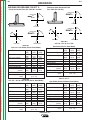
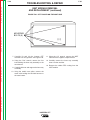
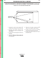
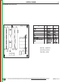
WELDING PROCEDURES FOR STT II -
(Stainless Steel) Horizontal Fillet
(See Table B.3 and B.4)
(Steel) Horizontal Fillet (See Table B.1 and B.2)
DIRECTION
OF
TRAVEL
DIRECTION
OF
TRAVEL
75°
75°
TOP VIEW
TOP VIEW
DIRECTION
OF
TRAVEL
Return to Master TOC
Return to Master TOC
Return to Master TOC
Return to Section TOC
Return to Section TOC
Return to Section TOC
45°
DIRECTION
OF
TRAVEL
45°
75°
FRONT VIEW
END VIEW
END VIEW
14 ga
10 ga
(2.0)
(3.25)
0.045
0.045
(1.1)
(1.1)
100
170
(2.5)
(4.2)
260
280
40
65
7
5
105
120
12
12
(0.3)
(0.3)
25 (12)
1/4 - 3/8
(6.4 - 10)
Table B.2
75% CO2 - 25% Ar Gas Shield (Set for Steel Mode)
Plate Thickness “ (mm) 20 ga
(0.9)
Electrode size “ (mm)
0.035
(0.9)
WFS “/min (m/min)
100
(2.5)
Peak Current
225
Background Current
40
Tailout setting
8
Average Amperage
70
Travel Speed “/min
12
(m/min)
(0.3)
Gas Flow cfh (L/min)
Electrical Stickout “
(mm)
Table B.3
90% He, 7.5% Ar, 2.5% CO2
FRONT VIEW
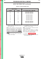
Table B.1
100% CO2 Gas Shield (Set for Steel Mode)
Plate Thickness “ (mm) 20 ga
(0.9)
Electrode size “ (mm)
0.035
(0.9)
WFS “/min (m/min)
100
(2.5)
Peak Current
220
Background Current
30
Tailout setting
3
Average Amperage
60
Travel Speed “/min
12
(m/min)
(0.3)
Gas Flow cfh (L/min)
Electrical Stickout “
(mm)
75°
14 ga
10 ga
(2.0)
(3.25)
0.045
0.045
(1.1)
(1.1)
100
120
(2.5)
(3.0)
270
310
65
70
4
6
110
130
12
12
(0.3)
(0.3)
25 (12)
1/4 - 3/8
(6.4 - 10)
Gas Shield (Set for Steel Mode)
Plate Thickness “ (mm) 20 ga
(0.9)
Electrode size “ (mm)
0.035
(0.9)
WFS “/min (m/min)
100
(2.5)
Peak Current
165
Background Current
35
Tailout setting
7
Average Amperage
40
Travel Speed “/min
12
(m/min)
(0.3)
Gas Flow cfh (L/min)
Electrical Stickout “
(mm)
14 ga
10 ga
(2.0)
(3.25)
0.045
0.045
(1.1)
(1.1)
130
170
(3.3)
(4.2)
210
250
60
85
7
4
95
120
16
16
(0.4)
(0.4)
25 (12)
1/4 - 3/8
(6.4 - 10)
Table B.4
98% Ar, 2% O2
Gas Shield (Set for Stainless Steel Mode)
Plate Thickness “ (mm) 20 ga
(0.9)
Electrode size “ (mm)
0.035
(0.9)
WFS “/min (m/min)
100
(2.5)
Peak Current
145
Background Current
45
Tailout setting
7
Average Amperage
60
Travel Speed “/min
12
(m/min)
(0.3)
Gas Flow cfh (L/min)
Electrical Stickout “
(mm)
INVERTEC STT
14 ga
10 ga
(2.0)
(3.25)
0.045
0.045
(1.1)
(1.1)
130
170
(3.3)
(4.2)
190
280
95
95
8
7
120
150
12
12
(0.3)
(0.3)
25 (12)
1/4 - 3/8
(6.4 - 10)
Return to Section TOC
Return to Master TOC
Return to Section TOC
Return to Master TOC
Return to Master TOC
Return to Section TOC
Return to Master TOC
Return to Section TOC
B-8
NOTES
INVERTEC STT
B-8
Section C-1
TABLE OF CONTENTS
- ACCESSORIES Accessories...........................................................................................................................Section C
Options/Accessories ...................................................................................................................C-2
LN-742 Wire Feeder Connection Instructions.............................................................................C-3
Connection Diagram ...................................................................................................................C-4
Return to Master TOC
Return to Master TOC
Return to Master TOC
Return to Master TOC
Section C-1
INVERTEC STT
Return to Master TOC
Return to Section TOC
C-2
ACCESSORIES
OPTIONS / ACCESSORIES
K940 SENSE LEADS: These leads are used to accurately sense arc voltage. One set is required for each
STT II power source. A 10 ft and 25 ft set are provided as standard with the machine. Additional sets are
available in 10 ft (K940-10), 25 ft (K940-25) and 50 ft
(K940-50) lengths.
K942-1 REMOTE CONTROL: Allows remote adjustment of Peak and Background Current settings.
Return to Master TOC
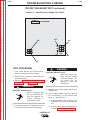
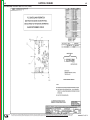
REMOTE RECEPTACLE (For optional remote interface,
Connection to the STT-10 Wire Feeder or Robotic Control)
Return to Section TOC
C-2
1. The 10 pin MS connector labeled “Remote Control”
located on the front panel of the STT is used for
remote control of the power source. Control for the
PEAK (PB pot) and BACKGROUND (BG pot) current along with the trigger switch is provide through
this connector.
2. Refer to figure C.1 below for details about the
remote receptacle (J38). Note that pins “J” and “B”
are shorted together This “short circuit” tells the
STT control board to accept PEAK and BACKGROUND inputs on this connector rather than from
the front panel controls. If this short is removed, the
front panel controls will be active. By adding a switch
between pins “J” and “B” a “LOCAL/REMOTE” control switch can be created. (Switch open for “local”
and closed for “remote”)
3. For robotic control of the PEAK CURRENT, a 0 to
+10 volt DC signal is applied between pins “A” and
“G” with + applied to pin “G”. The BACKGROUND
CURRENT is controlled with a similar signal applied
between pins “A” and “C” with + applied to pin “C”.
In this application pins “J” and “B” must be shorted
as described in 2 above.
NOTE: These analog signals should be isolated
from the robot circuitry to prevent interference.
4. The trigger switch is connected between pins “D”
and “F”. These connections are in parallel with the
trigger switch from the wire feeder.
5. The digital meters for PEAK and BACKGROUND
currents will show preset values in both local and
remote operation.
REMOTE
PROTECTION BOARD
+ ARC
Return to Master TOC
Return to Section TOC
J19
1
J37
- ARC
223
Return to Master TOC
1 (+)
2
291
3 (-)
2
3
SENSE
CONNECTION
4
4
J38
3
J
2
B
1
C
10
G
9
A
4
12
D
8
4
F
5
11
H
212C
6
43A
1
33C
32C
212B
Return to Section TOC
290
VOLTAGE
J38
3
E
2
I
7
8
290A
BG
10K
PB
TRIGGER
10K
GND
OPTIONAL
REMOTE
INTERFACE
WIRE
FEEDER
J39
N
ELECTRODE SENSE LEAD
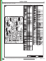
PORTION OF G3136 WIRING DIAGRAM
REFER TO ACTUAL DIAGRAM PASTED INSIDE YOUR MACHINE
INVERTEC STT
Return to Master TOC
Return to Section TOC
C-3
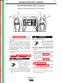
ACCESSORIES
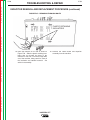
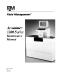
LN-742 or STT-10 WIRE FEEDER
CONNECTION INSTRUCTIONS
The LN-742 or STT-10 is the recommended wire feeder for use with the Invertec STT II. Refer to the LN742 or STT-10 Operator Manual for Wire Feed
Operation. Refer to Figure C.2 or C.3 and follow the
instructions below to connect the LN-742 or STT-10.
WARNING
• Only qualified personnel should perform
this installation.
Return to Master TOC
3. Connect the electrode lead (Twist-Mate) to (+) output terminal on STT II.
4. Connect the other end of electrode lead (Step #3)
and the ARC SENSE LEAD (lead with ring lug, step
#2) together to the gun block on the LN 742.
5. Connect work lead between STT (-) terminal and the
work piece.
6. Connect the ARC SENSE LEAD “WORK” (lead with
alligator clip) to work piece.
ELECTRIC SHOCK can kill.
Return to Section TOC
C-3
• Turn the input power OFF at the disconnect switch or fuse box before connecting
the wire feeder
1. Turn the Invertec STT II power off.
2. Connect the ARC SENSE LEAD MS connector to
the mating connector on STT II front panel.
NOTE: For best welding performance make this
connection as close as possible to the
welding arc.
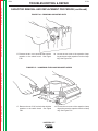
7. Connect the wire feeder control cable between the
LN-742 or STT-10 and the 14-pin Wire Feeder
Receptacle on the STT II. For the STT-10 Wire
Feeder: Connect the second wire feeder control
cable between the STT-10 and the 10-pin Remote
Receptacle on the STT II.
WARNING
Turn off input power to the Welding
Power source using the disconnnect
switch at the fuse box before
connecting the wire feeder.
Return to Master TOC
Return to Section TOC
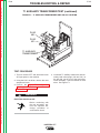
ELECTRIC
SHOCK
CAN KILL
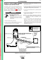
CONTROL, ELECTRODE, ARC SENSE "ELECT"
AND ARC SENSE "WORK" CABLES SHOULD
BE TAPED TOGETHER.
REMOTE RECEPTACLE
Only qualified persons should install,
use or service this machine.
WIRE FEEDER
LN 742
LN7 GMA
LN9 GMA
NA5R
NA5
WIRE FEEDER
CONTROL CABLE
WORK LEAD
ELECTRODE LEAD
ARC SENSE LEAD
’ELECT"
Return to Master TOC
Return to Section TOC
WORK
CONNECT ELECTRODE LEAD AND "ELECT"
ARC SENSE LEAD TOGETHER TO ELECTRODE
TERMINAL OF WIRE FEEDER.
ARC SENSE LEAD "WORK"
(SHOULD BE LOCATED
AS CLOSE AS POSSIBLE
TO THE WELDING ARC.)
CRM after 6-10-96
M17657
FIGURE C.2 LN-742 to STT II CONNECTION
INVERTEC STT
C-4
ACCESSORIES
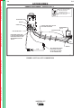
CONNECTION DIAGRAM - INVERTEC STT II
Return to Master TOC
Return to Section TOC
C-4
WARNING
Turn off input power to the Welding
Power source using the disconnnect
switch at the fuse box before
connecting the wire feeder.
ELECTRIC
SHOCK
Only qualified persons should install,
use or service this machine.
CAN KILL
WIRE FEEDER
REMOTE
WORK LEAD
CABLES AND LEADS SHOULD
BE TAPED TOGETHER.
ELECTRODE LEAD
Return to Master TOC
ELECTRODE LEAD
Return to Section TOC
WIRE FEEDER
STT-10
ELECTRODE SENSE LEAD
IS BOLTED TOGETHER WITH
ELECTRODE LEAD ON THE
WIRE FEEDER CONTACT
BLOCK
WIRE
FEEDER
REMOTE
ARC SENSE LEAD "WORK"
WORK
(SHOULD BE LOCATED
AS CLOSE AS POSSIBLE
TO THE WELDING ARC)
4-9-99
M17657-3
Return to Section TOC
Return to Master TOC
Return to Section TOC
Return to Master TOC
FIGURE C.3 STT-10 to STT II CONNECTION
INVERTEC STT
Section D-1
TABLE OF CONTENTS
-MAINTENANCEMaintenance .........................................................................................................................Section D
Input Filter Capacitor Discharge Procedure................................................................................D-2
Preventive Maintenance .............................................................................................................D-3
Major Component Locations .......................................................................................................D-4
Return to Master TOC
Return to Master TOC
Return to Master TOC
Return to Master TOC
Section D-1
INVERTEC STT
Return to Master TOC
Return to Section TOC
D-2
MAINTENANCE
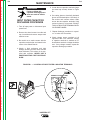
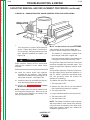
WARNING
Failure to follow this
capacitor discharge procedure can result in electric
shock.
INPUT FILTER CAPACITOR
DISCHARGE PROCEDURE
Return to Master TOC
Return to Section TOC
1. Turn off input power or disconnect input
power lines.
2. Remove hex head screws from side and
top of machine and remove wrap-around
machine cover.
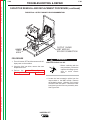
3. Be careful not to make contact with the
capacitor terminals that are located in the
center of the Switch Boards.
4. Obtain a high resistance and high
wattage resistor (25-1000 ohms and 25
watts minimum). This resistor is not supplied with machine. NEVER USE A
SHORTING STRAP FOR THIS PROCEDURE.
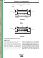
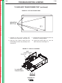
5. Locate the two capacitor terminals (large
hex head cap screws) shown in Figure
D.1.
6. Use safety glasses, electrically insulated
gloves and insulated pliers. Hold body of
the resistor and connect resistor leads
across the two capacitor terminals. Hold
resistor in place for 10 seconds. DO NOT
TOUCH CAPACITOR TERMINALS WITH
YOUR BARE HANDS.
7. Repeat discharge procedure for capacitor on other side of machine.
8. Check voltage across terminals of all
capacitors with a DC voltmeter. Polarity
of capacitor terminals is marked on PC
board above terminals. Voltage should be
zero. If any voltage remains, repeat this
capacitor discharge procedure.
Return to Section TOC
Return to Master TOC
Return to Section TOC
Return to Master TOC
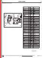
FIGURE D.1 — LOCATION OF INPUT FILTER CAPACITOR TERMINALS.
INVERTEC STT
D-2
Return to Master TOC
Return to Section TOC
D-3
MAINTENANCE
PREVENTIVE MAINTENANCE
• Input Filter Capacitors
1. Perform the following preventive maintenance procedures at least once every six
months. It is good practice to keep a preventive maintenance record; a record tag
attached to the machine works best.
• Output Terminals
Return to Master TOC
Return to Section TOC
2. Remove the machine wraparound cover
and perform the input filter capacitor discharge procedure (detailed at the beginning of this chapter).
3. Clean the inside of the machine with a
low pressure airstream. Be sure to clean
the following components thoroughly.
• Power Switch, Driver, Protection, and
Control printed circuit boards
• Power Switch
• Main Transformer
• Lower base compartment
4. Examine capacitors for leakage or oozing.
Replace if needed.
5. Examine wraparound cover for dents or
breakage. Repair as needed. Cover must
be kept in good condition to assure high
voltage parts are protected and correct
spacings are maintained.
6. Check electrical ground continuity. Using
an ohmmeter, measure resistance
between either output stud and an unpainted surface of the machine case. Meter
reading should be 500,000 ohms or more.
If meter reading is less than 500,000
ohms, check for electrical components that
are not properly insulated from the case.
Correct insulation if needed.
• Input Rectifier
7. Replace machine cover and screws.
Return to Section TOC
Return to Master TOC
Return to Section TOC
Return to Master TOC
• Heat Sink Fins
INVERTEC STT
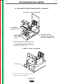
D-3
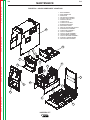
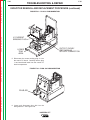
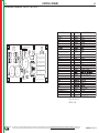
FIGURE D.2 – MAJOR COMPONENT LOCATIONS
1.
2.
3.
4.
5.
6.
7.
8.
9.
10.
11.
12.
13.
14.
15.
16.
17.
18.
19.
Return to Master TOC
12
Return to Section TOC
D-4
MAINTENANCE
Return to Master TOC
Return to Section TOC
D-4
BASE ASSEMBLY
REAR NAMEPLATE
RESISTORS
FAN SHROUD ASSEMBLY
PROTECTION PC BOARD
DRIVER PC BOARD
CONTROL BOX
CONTROL PC BOARD
BLEEDER RESISTORS
RECONNECT PANEL
IGBT OR DARLINGTON MODULE
WRAPAROUND ASSEMBLY
CASE FRONT ASSEMBLY
OUTPUT TERMINALS
OUTPUT CHOKE ASSEMBLY
TRANSFORMER ASSEMBLY
OUTPUT RECTIFIER ASSEMBLY
AUXILIARY TRANSFORMER
FET HEAT SINK ASSEMBLY
4
6
9
5
8
10
17
15
Return to Master TOC
Return to Section TOC
7
16
2
18
13
19
3
Return to Master TOC
Return to Section TOC
14
1
11
INVERTEC STT
Return to Master TOC
Section E-1
Section E-1
TABLE OF CONTENTS
-THEORY OF OPERATION SECTIONTheory of Operation .............................................................................................................Section E
General Description ...............................................................................................................E-2
Input Voltage..........................................................................................................................E-2
Reconnect, Protection Board, Rectification and Precharge ..................................................E-3
Switch Boards........................................................................................................................E-4
Main Transformer, Output Rectification and Choke...............................................................E-5
Control Board, IGBT Drive and Module.................................................................................E-6
Power Board ..........................................................................................................................E-7
Remote Protection Board ......................................................................................................E-7
Field Effect Transistor (FET) Operation.................................................................................E-8
Return to Master TOC
Pulse Width Modulation .........................................................................................................E-9
Minimum Output ..............................................................................................................E-9
Maximum Output .............................................................................................................E-9
Protective Circuits................................................................................................................E-10
Overload Protection.......................................................................................................E-10
Thermal Protection ........................................................................................................E-10
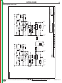
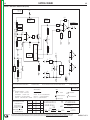
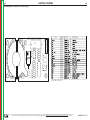
POSITIVE
OUTPUT
TERMINAL
MAIN
TRANSFORMER
T2
Return to Master TOC
S
W
I
T
C
H
LINE
SWITCH
FET
CAP
FET
B
O
A
R
D
INPUT
RECTIFIER
R
E
C
O
N
N
E
C
T
"A"
LEAD
115
VAC
TRANS
T4
18
VAC
2
4
V
A
C
T
H
E
R
M
O
S
T
A
T
P
O
W
E
R
B
O
A
R
D
B
O
A
R
D
D
R
I
V
E
R
B
O
A
R
D
D
R
I
V
E
CURRENT
TRANS
T3
S
I
G
N
A
L
PRE CHARGE
S
W
I
T
C
H
FET
CAP
FET
B
O
A
R
D
CURRENT FEEDBACK
LESS THAN 1VDC
PULSE TRANSFORMER SIGNAL
PWM SIGNAL
15VDC
GUN TRIGGER
IGBT
DRIVER
BOARD
CONTROL BOARD
36VAC
VOLTAGE FEEDBACK
Return to Master TOC
IGBT
MODULE
BACKPEAK
TAILOUT CURRENT
GROUND
CONTROL
METER
METER
(STT II ONLY)
NEGATIVE
OUTPUT
TERMINAL
CHOKE
P
R
O
T
E
C
T
I
O
N
CR2
TRANS
T1
CURRENT
SENSOR
PRE CHARGE
CR1
FAN
1 OHM
WIRE
BACKPEAK
HOT
SIZE
GROUND
CURRENT START
CONTROL CONTROL CONTROL SWITCH
WIRE
TYPE
SWITCH
10VAC AND 6VAC
42VAC
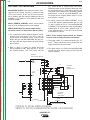
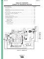
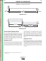
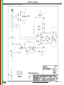
FIGURE E.1 – INVERTEC STT
INVERTEC STT
R
E
M
O
T
E
P
R
O
T
E
C
T
I
O
N
VOLTAGE
SENSING
RECEPTACLE
B
O
A
REMOTE
CONTROL
RECEPTACLE
R
D
WIRE
FEEDER
RECEPTACLE
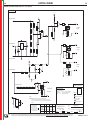
E-2
THEORY OF OPERATION
Return to Master TOC
Return to Section TOC
E-2
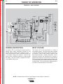
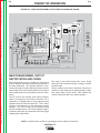
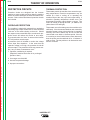
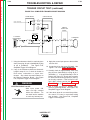
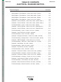
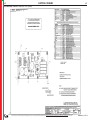
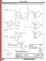
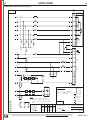
FIGURE E.2 – INPUT VOLTAGE
POSITIVE
OUTPUT
TERMINAL
MAIN
TRANSFORMER
T2
S
W
I
T
C
H
LINE
SWITCH
Return to Master TOC
FET
B
O
A
R
D
CURRENT
SENSOR
INPUT
RECTIFIER
R
E
C
O
N
N
E
C
T
"A"
LEAD
TRANS
T1
115
VAC
TRANS
T4
18
VAC
2
4
V
A
C
T
H
E
R
M
O
S
T
A
T
P
O
W
E
R
B
O
A
R
D
P
R
O
T
E
C
T
I
O
N
B
O
A
R
D
D
R
I
V
E
R
B
O
A
R
D
D
R
I
V
E
CURRENT
TRANS
T3
S
I
G
N
A
L
PRE CHARGE
S
W
I
T
C
H
FET
CAP
FET
NEGATIVE
OUTPUT
TERMINAL
CHOKE
CR2
FAN
IGBT
MODULE
PRE CHARGE
CR1
Return to Section TOC
FET
CAP
1 OHM
B
O
A
R
D
R
E
M
O
T
E
P
R
O
T
E
C
T
I
O
N
VOLTAGE
SENSING
RECEPTACLE
B
O
A
REMOTE
CONTROL
RECEPTACLE
R
D
WIRE
FEEDER
RECEPTACLE
CURRENT FEEDBACK
LESS THAN 1VDC
PULSE TRANSFORMER SIGNAL
PWM SIGNAL
15VDC
GUN TRIGGER
IGBT
DRIVER
BOARD
CONTROL BOARD
36VAC
VOLTAGE FEEDBACK
BACKPEAK
TAILOUT CURRENT
GROUND
CONTROL
METER
METER
(STT II ONLY)
WIRE
BACKPEAK
HOT
SIZE
GROUND
CURRENT START
CONTROL CONTROL CONTROL SWITCH
WIRE
TYPE
SWITCH
10VAC AND 6VAC
Return to Section TOC
Return to Master TOC
Return to Section TOC
Return to Master TOC
42VAC
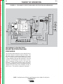
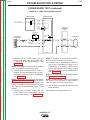
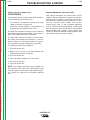
GENERAL DESCRIPTION
INPUT VOLTAGE
The Invertec STT is a 225 ampere, inverter based, arc
welding power supply specifically designed for the
Surface Tension Transfer (STT) welding process. It
cannot be classified as either a constant current (CC)
or a constant voltage (CV) machine. The STT produces current of a desired waveform to reduce spatter
and fumes. The STT process is optimized for short circuit GMAW welding only.
The Invertec STT can be connected for a variety of
three-phase voltages. The initial input power is applied
to the STT through a line switch located on the front of
the machine. The AC input voltage is applied to the
input rectifier and the T1 auxiliary transformer. The T1
transformer develops the appropriate AC voltages to
operate the cooling fan, the power and control boards.
The T1 transformer also supplies primary voltage to the
T4 auxiliary transformer as well as 42 VAC to an external wire feeder. The T4 transformer supplies power to
the IGBT drive board and the control board.
NOTE: Unshaded areas of Block Logic Diagram are the subject of discussion.
INVERTEC STT
Return to Master TOC
Return to Section TOC
E-3
E-3
THEORY OF OPERATION
FIGURE E.3 – RECONNECT, PROTECTION BOARD, RECTIFICATION AND PRECHARGE
POSITIVE
OUTPUT
TERMINAL
MAIN
TRANSFORMER
T2
S
W
I
T
C
H
LINE
SWITCH
Return to Master TOC
FET
B
O
A
R
D
INPUT
RECTIFIER
R
E
C
O
N
N
E
C
T
"A"
LEAD
TRANS
T1
115
VAC
TRANS
T4
18
VAC
2
4
V
A
C
T
H
E
R
M
O
S
T
A
T
IGBT
MODULE
P
O
W
E
R
B
O
A
R
D
B
O
A
R
D
D
R
I
V
E
R
B
O
A
R
D
D
R
I
V
E
CURRENT
TRANS
T3
S
I
G
N
A
L
PRE CHARGE
S
W
I
T
C
H
FET
CAP
FET
NEGATIVE
OUTPUT
TERMINAL
CHOKE
P
R
O
T
E
C
T
I
O
N
CR2
FAN
CURRENT
SENSOR
PRE CHARGE
CR1
Return to Section TOC
FET
CAP
1 OHM
B
O
A
R
D
R
E
M
O
T
E
P
R
O
T
E
C
T
I
O
N
CURRENT FEEDBACK
LESS THAN 1VDC
PULSE TRANSFORMER SIGNAL
PWM SIGNAL
15VDC
GUN TRIGGER
IGBT
DRIVER
BOARD
CONTROL BOARD
36VAC
VOLTAGE FEEDBACK
BACKPEAK
TAILOUT CURRENT
GROUND
CONTROL
METER
METER
(STT II ONLY)
WIRE
BACKPEAK
HOT
SIZE
GROUND
CURRENT START
CONTROL CONTROL CONTROL SWITCH
WIRE
TYPE
SWITCH
10VAC AND 6VAC
Return to Section TOC
Return to Master TOC
Return to Section TOC
Return to Master TOC
42VAC
RECONNECT, PROTECTION
BOARD, RECTIFICATION AND
PRECHARGE
The reconnect panel allows the user to switch to low or
high input voltage to match the input line voltage. The
AC input voltage is rectified and applied to the driver
board. The driver board contains precharging circuitry
for safe charging of the input filter capacitors. Once the
capacitors are precharged, the input relays are energized, connecting full input power to the input filter
capacitors. The protection board monitors the capacitors for voltage balance and/or overvoltage and will deenergize the input relays and precharge circuitry if
either occurs. The machine output will be disabled.
NOTE: Unshaded areas of Block Logic Diagram are the subject of discussion.
INVERTEC STT
VOLTAGE
SENSING
RECEPTACLE
B
O
A
REMOTE
CONTROL
RECEPTACLE
R
D
WIRE
FEEDER
RECEPTACLE
FIGURE E.4 – SWITCH BOARDS
POSITIVE
OUTPUT
TERMINAL
MAIN
TRANSFORMER
T2
S
W
I
T
C
H
LINE
SWITCH
FET
CAP
FET
Return to Master TOC
B
O
A
R
D
R
E
C
O
N
N
E
C
T
"A"
LEAD
TRANS
T1
115
VAC
TRANS
T4
18
VAC
2
4
V
A
C
T
H
E
R
M
O
S
T
A
T
CURRENT
SENSOR
IGBT
MODULE
P
O
W
E
R
B
O
A
R
D
B
O
A
R
D
D
R
I
V
E
R
B
O
A
R
D
D
R
I
V
E
CURRENT
TRANS
T3
S
I
G
N
A
L
PRE CHARGE
S
W
I
T
C
H
FET
CAP
FET
NEGATIVE
OUTPUT
TERMINAL
CHOKE
P
R
O
T
E
C
T
I
O
N
CR2
FAN
1 OHM
PRE CHARGE
INPUT
RECTIFIER
CR1
Return to Section TOC
E-4
THEORY OF OPERATION
Return to Master TOC
Return to Section TOC
E-4
B
O
A
R
D
R
E
M
O
T
E
P
R
O
T
E
C
T
I
O
N
CURRENT FEEDBACK
LESS THAN 1VDC
PULSE TRANSFORMER SIGNAL
PWM SIGNAL
15VDC
GUN TRIGGER
IGBT
DRIVER
BOARD
CONTROL BOARD
36VAC
VOLTAGE FEEDBACK
BACKPEAK
TAILOUT CURRENT
GROUND
CONTROL
METER
METER
(STT II ONLY)
WIRE
BACKPEAK
HOT
SIZE
GROUND
CURRENT START
CONTROL CONTROL CONTROL SWITCH
WIRE
TYPE
SWITCH
10VAC AND 6VAC
Return to Section TOC
Return to Master TOC
Return to Section TOC
Return to Master TOC
42VAC
SWITCH BOARDS
There are two switch boards in the Invertec STT, each
containing an input filter capacitor. The capacitors are
connected in parallel when the machine is connected
for "low" input voltage. The capacitors are connected
in series when the reconnect switch is configured for
"high" input voltage. When the capacitors are fully
charged, they act as power supplies for the switch
boards. The switch boards contain the Field Effect
Transistors (FETs) which, when switched on, supply
the main transformer primary windings with DC current
flow. See Field Effect Transistor (FET) Operation
discussion and diagrams. See Figure E.4.
NOTE: Unshaded areas of Block Logic Diagram are the subject of discussion.
INVERTEC STT
VOLTAGE
SENSING
RECEPTACLE
B
O
A
REMOTE
CONTROL
RECEPTACLE
R
D
WIRE
FEEDER
RECEPTACLE
FIGURE E.5 – MAIN TRANSFORMER, OUTPUT RECTIFICATION AND CHOKE
POSITIVE
OUTPUT
TERMINAL
MAIN
TRANSFORMER
T2
S
W
I
T
C
H
LINE
SWITCH
Return to Master TOC
FET
CAP
FET
B
O
A
R
D
INPUT
RECTIFIER
R
E
C
O
N
N
E
C
T
"A"
LEAD
TRANS
T1
115
VAC
TRANS
T4
18
VAC
2
4
V
A
C
T
H
E
R
M
O
S
T
A
T
CURRENT
SENSOR
IGBT
MODULE
P
O
W
E
R
B
O
A
R
D
B
O
A
R
D
D
R
I
V
E
R
B
O
A
R
D
D
R
I
V
E
CURRENT
TRANS
T3
S
I
G
N
A
L
PRE CHARGE
S
W
I
T
C
H
FET
CAP
FET
NEGATIVE
OUTPUT
TERMINAL
CHOKE
P
R
O
T
E
C
T
I
O
N
CR2
FAN
1 OHM
PRE CHARGE
CR1
Return to Section TOC
E-5
THEORY OF OPERATION
Return to Master TOC
Return to Section TOC
E-5
B
O
A
R
D
R
E
M
O
T
E
P
R
O
T
E
C
T
I
O
N
VOLTAGE
SENSING
RECEPTACLE
B
O
A
REMOTE
CONTROL
RECEPTACLE
R
D
WIRE
FEEDER
RECEPTACLE
CURRENT FEEDBACK
LESS THAN 1VDC
PULSE TRANSFORMER SIGNAL
PWM SIGNAL
15VDC
GUN TRIGGER
IGBT
DRIVER
BOARD
CONTROL BOARD
36VAC
VOLTAGE FEEDBACK
BACKPEAK
TAILOUT CURRENT
GROUND
CONTROL
METER
METER
(STT II ONLY)
WIRE
BACKPEAK
HOT
SIZE
GROUND
CURRENT START
CONTROL CONTROL CONTROL SWITCH
WIRE
TYPE
SWITCH
10VAC AND 6VAC
Return to Master TOC
Return to Master TOC
Return to Section TOC
Return to Section TOC
42VAC
MAIN TRANSFORMER, OUTPUT
RECTIFICATION AND CHOKE
Each switch board works as a switch pair. Each board
feeds a separate, oppositely wound primary winding of
the main transformer. The opposite directions of current flow through the main transformer primary and the
offset timing of the switch boards induce an AC square
wave output signal at the secondary of the main transformer.
The firing of both switch board pairs occurs during
halves of 50 microsecond intervals, creating a constant
20 KHZ output.
The AC output from the main transformer secondary is
rectified to a DC output and is applied through a stabilizer output choke, current sensor, IGBT module and
remote protection board to the output terminals.
The DC current flow through each primary winding,
which is monitored by the current transformer T3, is
redirected or "clamped" back to each respective input
capacitor when the FETs are turned off. This is needed due to the inductance of the transformer primary
windings. The cross coupling of the primaries along
with the clamping action of the diode maintain capacitor balance when they are connected in the series (high
voltage) input configuration.
NOTE: Unshaded areas of Block Logic Diagram are the subject of discussion.
INVERTEC STT
FIGURE E.6 – CONTROL BOARD, IGBT DRIVE AND MODULE
POSITIVE
OUTPUT
TERMINAL
MAIN
TRANSFORMER
T2
S
W
I
T
C
H
LINE
SWITCH
Return to Master TOC
FET
CAP
FET
B
O
A
R
D
R
E
C
O
N
N
E
C
T
"A"
LEAD
TRANS
T1
115
VAC
TRANS
T4
18
VAC
2
4
V
A
C
T
H
E
R
M
O
S
T
A
T
CURRENT
SENSOR
IGBT
MODULE
P
O
W
E
R
B
O
A
R
D
B
O
A
R
D
D
R
I
V
E
R
B
O
A
R
D
D
R
I
V
E
CURRENT
TRANS
T3
S
I
G
N
A
L
PRE CHARGE
S
W
I
T
C
H
FET
CAP
FET
NEGATIVE
OUTPUT
TERMINAL
CHOKE
P
R
O
T
E
C
T
I
O
N
CR2
FAN
1 OHM
PRE CHARGE
INPUT
RECTIFIER
CR1
Return to Section TOC
E-6
THEORY OF OPERATION
Return to Master TOC
Return to Section TOC
E-6
B
O
A
R
D
R
E
M
O
T
E
P
R
O
T
E
C
T
I
O
N
VOLTAGE
SENSING
RECEPTACLE
B
O
A
REMOTE
CONTROL
RECEPTACLE
R
D
WIRE
FEEDER
RECEPTACLE
CURRENT FEEDBACK
LESS THAN 1VDC
PULSE TRANSFORMER SIGNAL
PWM SIGNAL
15VDC
GUN TRIGGER
IGBT
DRIVER
BOARD
CONTROL BOARD
36VAC
VOLTAGE FEEDBACK
BACKPEAK
TAILOUT CURRENT
GROUND
CONTROL
METER
METER
(STT II ONLY)
WIRE
BACKPEAK
HOT
SIZE
GROUND
CURRENT START
CONTROL CONTROL CONTROL SWITCH
WIRE
TYPE
SWITCH
10VAC AND 6VAC
Return to Section TOC
Return to Master TOC
Return to Section TOC
Return to Master TOC
42VAC
CONTROL BOARD, IGBT DRIVE
AND MODULE
The control board monitors the directives of the various
controls and compares these commands to the current
and voltage feedback information received from the
current sensor and voltage sensing receptacle. This
data is processed and the suitable PWM signal is sent
to the power board. (See Pulse Width Modulation
discussion).
The control board also determines when the IGBT
module should be switched OFF to reduce weld spatter and fumes. The appropriate signal is sent to the
IGBT drive board which then applies, or removes, the
gate drive signal to the IGBT module. When the IGBT
module is in the OFF state, the welding current must
pass through the one ohm resistance. This reduces
the current and, subsequently, spatter and fumes.
NOTE: Unshaded areas of Block Logic Diagram are the subject of discussion.
INVERTEC STT
FIGURE E.7 – POWER BOARD AND REMOTE PROTECTION BOARD
POSITIVE
OUTPUT
TERMINAL
MAIN
TRANSFORMER
T2
S
W
I
T
C
H
LINE
SWITCH
Return to Master TOC
FET
CAP
FET
B
O
A
R
D
R
E
C
O
N
N
E
C
T
"A"
LEAD
TRANS
T1
115
VAC
TRANS
T4
18
VAC
2
4
V
A
C
T
H
E
R
M
O
S
T
A
T
CURRENT
SENSOR
IGBT
MODULE
P
O
W
E
R
B
O
A
R
D
B
O
A
R
D
D
R
I
V
E
R
B
O
A
R
D
D
R
I
V
E
CURRENT
TRANS
T3
S
I
G
N
A
L
PRE CHARGE
S
W
I
T
C
H
FET
CAP
FET
NEGATIVE
OUTPUT
TERMINAL
CHOKE
P
R
O
T
E
C
T
I
O
N
CR2
FAN
1 OHM
PRE CHARGE
INPUT
RECTIFIER
CR1
Return to Section TOC
E-7
THEORY OF OPERATION
Return to Master TOC
Return to Section TOC
E-7
B
O
A
R
D
R
E
M
O
T
E
P
R
O
T
E
C
T
I
O
N
VOLTAGE
SENSING
RECEPTACLE
B
O
A
REMOTE
CONTROL
RECEPTACLE
R
D
WIRE
FEEDER
RECEPTACLE
CURRENT FEEDBACK
LESS THAN 1VDC
PULSE TRANSFORMER SIGNAL
PWM SIGNAL
15VDC
GUN TRIGGER
IGBT
DRIVER
BOARD
CONTROL BOARD
36VAC
VOLTAGE FEEDBACK
BACKPEAK
TAILOUT CURRENT
GROUND
CONTROL
METER
METER
(STT II ONLY)
WIRE
BACKPEAK
HOT
SIZE
GROUND
CURRENT START
CONTROL CONTROL CONTROL SWITCH
WIRE
TYPE
SWITCH
10VAC AND 6VAC
Return to Master TOC
Return to Section TOC
42VAC
POWER BOARD
REMOTE PROTECTION BOARD
The power board creates a pulse transformer drive signal, which is derived from the PWM signal received
from the control board. See Pulse Width Modulation
discussion. This drive signal is applied to the primary
winding of the pulse transformer, which is located on
the driver board. The pulse transformer secondary
windings generate the proper gate pulse for the switch
board FETs. See Field Effect Transistor (FET)
Operation.
The remote protection board provides noise suppression and by-pass filtering to protect the internal circuitry of the STT machine.
Return to Master TOC
Return to Section TOC
The power board supplies a 15VDC supply voltage for
the control board and also powers the input relays
(CR1 and CR2).
NOTE: Unshaded areas of Block Logic Diagram are the subject of discussion.
INVERTEC STT
Return to Master TOC
Return to Section TOC
E-8
THEORY OF OPERATIONS
FIGURE E-8 – FIELD EFFECT TRANSISTOR OPERATION
GATE
TERMINAL
(0 VOLTS)
SOURCE
TERMINAL
DRAIN
TERMINAL
DRAIN (N)
SUBSTRATE (P)
Return to Master TOC
Return to Section TOC
SOURCE (N)
N CHANNEL
A. PASSIVE
GATE
TERMINAL
(+ 6 VOLTS)
Return to Master TOC
Return to Section TOC
SOURCE (N)
DRAIN (N)
ELECTRONS
B. ACTIVE
FIELD EFFECT TRANSISTOR (FET)
OPERATION
Return to Master TOC
An FET is a type of transistor. FETs are semiconductors well suited for high-frequency switching.
Return to Section TOC
E-8
Drawing A above shows an FET in a passive mode.
There is no gate signal, zero volts relative to the source
and, therefore, no current flow. The drain terminal of
the FET may be connected to a voltage supply; but
since there is no conduction, the circuit will not supply
current to downstream components connected to the
source. The circuit is turned off like a light switch in the
OFF position.
Drawing B above shows the FET in an active mode.
When the gate signal, a positive DC voltage relative to
the source, is applied to the gate terminal of the FET, it
is capable of conducting current. A voltage supply connected to the drain terminal will allow the FET to conduct and henceforth supply current to downstream
components. Current will flow through the conducting
FET to downstream components as long as the gate
signal is present. This is similar to turning on a light
switch.
INVERTEC STT
Return to Master TOC
Return to Section TOC
E-9
THEORY OF OPERATION
E-9
FIGURE E-9 – TYPICAL FET OUTPUTS
sec
48
50
sec
sec
sec
Return to Master TOC
Return to Section TOC
MINIMUM OUTPUT
24 sec
24 sec
2 sec
50 sec
MAXIMUM OUTPUT
Return to Section TOC
Return to Master TOC
Return to Section TOC
Return to Master TOC
PULSE WIDTH MODULATION
The term PULSE WIDTH MODULATION is used to
describe how much time is devoted to conduction in
the positive and negative portions of the cycle.
Changing the pulse width is known as MODULATION.
Pulse Width Modulation (PWM) is the varying of the
pulse width over the allowed range of a cycle to affect
the output of the machine.
MINIMUM OUTPUT
By controlling the duration of the gate signal, the FET
is turned on and off for different durations during a
cycle. The top drawing above shows the minimum output signal possible over a 50-microsecond time period.
1
The positive portion of the signal represents one FET
group1 conducting for 1 microsecond. The negative
portion is the other FET group1. The dwell time (off
time) is 48 microseconds (both FET groups off). Since
only 2 microseconds of the 50-microsecond time period is devoted to conducting, the output power is minimized.
MAXIMUM OUTPUT
By holding the gate signals on for 24 microseconds
each and allowing only 2 microseconds of dwell time
(off time) during the 50-microsecond cycle, the output
is maximized. The darkened area under the top curve
can be compared to the area under the bottom curve.
The more dark area under the curve, the more power
is present.
A FET group consists of the sets of FET modules grouped onto
one switch board.
INVERTEC STT
Return to Master TOC
Return to Section TOC
E-10
THEORY OF OPERATION
PROTECTIVE CIRCUITS
THERMAL PROTECTION
Protective circuits are designed into the Invertec
machine to sense trouble and shut down the machine
before the trouble damages the internal machine components. Both overload and thermal protection circuits
are included.
Thermostats protect the machine from excessive operating temperatures. Excessive temperatures may be
caused by a lack of cooling air or operating the
machine beyond the duty cycle and output rating. If
excessive operating temperature should occur, the
thermostat will prevent output voltage or current. The
meter will remain on during this time. (In addition, the
yellow thermo LED will light.)
Return to Master TOC
Return to Section TOC
OVERLOAD PROTECTION
The machine is electrically protected from producing
abnormally high output currents due to short electrode
“stick-out” or the nozzle shorting to the work. Should
the output current exceed 500 amps, an electronic protection circuit will reduce the current to zero amps.
Five seconds after the “short” is removed the Invertec
STT will produce normal output.
A protection circuit is included to monitor the voltage
across input filter capacitors. In the event that the
capacitor voltage is too high, the protection circuit will
prevent output. The protection circuit may prevent output, if any of these circumstances occur:
Thermostats are self-resetting once the machine cools
sufficiently. If the thermostat shutdown was caused by
excessive output or duty cycle and the fan is operating
normally, the Power Switch may be left on and the
reset should occur within a 15-minute period. If the fan
is not turning or the air intake louvers were obstructed,
then the power must be switched off for 15 minutes in
order to reset. The fan problem or air obstruction must
also be corrected.
1. Capacitor conditioning is required
(Required if machine has been off for prolonged
periods of time.)
2. Line surges over 500 VAC
3. Internal Component damage
Return to Section TOC
Return to Master TOC
Return to Master TOC
4. Improper connections
Return to Section TOC
E-10
INVERTEC STT
Return to Master TOC
Return to Master TOC
Section F-1
Section F-1
TABLE OF CONTENTS
TROUBLESHOOTING & REPAIR SECTION
Troubleshooting & Repair Section ................................................................................Section F
How to Use Troubleshooting Guide .......................................................................................F-2
PC Board Troubleshooting Procedures .................................................................................F-3
Troubleshooting Guide .................................................................................................F4 - F-12
Test Procedures ...................................................................................................................F-13
T1 Auxiliary Transformer Test........................................................................................F-13
T4 Auxiliary Transformer Test........................................................................................F-19
Input Rectifier Test.........................................................................................................F-25
Capacitor Balance Test .................................................................................................F-29
Switch Board Test..........................................................................................................F-33
Snubber Resistors Test .................................................................................................F-37
Power Board Test ..........................................................................................................F-41
Protection Board Test ....................................................................................................F-45
Trigger Circuit Test ........................................................................................................F-49
Replacement Procedures ....................................................................................................F-53
IGBT Module Removal and Replacement.....................................................................F-53
Switch Board Replacement ...........................................................................................F-59
Capacitor Removal and Replacement Procedure.........................................................F-65
Output Rectifier Removal and Replacement.................................................................F-73
Return to Master TOC
Return to Master TOC
Retest After Repair...............................................................................................................F-77
INVERTEC STT
Return to Master TOC
Return to Master TOC
Return to Section TOC
Return to Section TOC
F-2
TROUBLESHOOTING & REPAIR
HOW TO USE TROUBLESHOOTING GUIDE
WARNING
Service and repair should be performed by only Lincoln Electric Factory Trained Personnel.
Unauthorized repairs performed on this equipment may result in danger to the technician and machine
operator and will invalidate your factory warranty. For your safety and to avoid Electrical Shock, please
observe all safety notes and precautions detailed throughout this manual.
This Troubleshooting Guide is provided to help
you locate and repair possible machine malfunctions. Simply follow the three-step procedure listed below.
Step 1. LOCATE PROBLEM (SYMPTOM). Look
under the column labeled “PROBLEM (SYMPTOMS). This column describes possible symptoms that the machine may exhibit. Find the listing that best describes the symptom that the
machine is exhibiting. Symptoms are grouped
into two main categories: Output Problems, and
Welding Problems.
Return to Master TOC
Return to Section TOC
Step 2. PERFORM EXTERNAL TESTS. The
second column, labeled “POSSIBLE AREAS OF
MISADJUSTMENT(S)”, lists the obvious external
possibilities that may contribute to the machine
symptom. Perform these tests/checks in the order
listed. In general, these tests can be conducted
without removing the case wrap-around cover.
Step 3. PERFORM COMPONENT TESTS. The
last column, labeled “Recommended Course of
Action” lists the most likely components that may
have failed in your machine. It also specifies the
appropriate test procedure to verify that the subject component is either good or bad. If there are
a number of possible components, check the
components in the order listed to eliminate one
possibility at a time until you locate the cause of
your problem.
All of the referenced test procedures referred to in
the Troubleshooting Guide are described in detail
at the end of this chapter.
Refer to the
Troubleshooting and Repair Table of Contents to
locate each specific Test Procedure. All of the
referred to test points, components, terminal
strips, etc., can be found on the referenced electrical wiring diagrams and schematics. Refer to
the Electrical Diagrams Section Table of
Contents to locate the appropriate diagram.
OSCILLOSCOPE WARNING
WARNING
Return to Master TOC
Return to Section TOC
Do not use oscilloscopes and other test equipment which are powered by 115 VAC. This equipment
should not be used with inverter-type machines, such as Invertec STT. There are high voltages present, which are “floating” off case ground (floating ground). Connecting the ground lead of a test probe
(which may be connected to the case of the test equipment) to a high voltage potential presents a shock
hazard as well as the possibility of damage to the equipment in question.
CAUTION
If for any reason you do not understand the test procedures or are unable to perform the test/repairs
safely, contact the Lincoln Electric Service Department for electrical troubleshooting assistance before
you proceed. Call1-888-935-3877.
INVERTEC STT
F-2
Return to Master TOC
Return to Master TOC
Return to Section TOC
Return to Section TOC
F-3
TROUBLESHOOTING & REPAIR
PC BOARD TROUBLESHOOTING PROCEDURES
WARNING
ELECTRIC SHOCK can kill.
Have an electrician install and service
this equipment. Turn the machine OFF
before working on equipment. Do not
touch electrically hot parts.
Sometimes machine failures appear to be due to PC
board failures. These problems can sometimes be
traced to poor electrical connections. To avoid problems when troubleshooting and replacing PC boards,
please use the following procedure:
Return to Master TOC
Return to Section TOC
• If the PC Board uses protective shorting jumpers,
don’t remove them until installation is complete.
• If you return a PC Board to The Lincoln Electric
Company for credit, it must be in the static-shielding
bag. This will prevent further damage and allow proper failure analysis.
4. Test the machine to determine if the failure symptom has been corrected by the replacement PC
board.
NOTE: Allow the machine to heat up so that all electrical components can reach their operating temperature.
2. Check for loose connections at the PC board to
assure that the PC board is properly connected.
5. Remove the replacement PC board and substitute
it with the original PC board to recreate the original
problem.
a. If the original problem does not reappear
by substituting the original board, then the
PC board was not the problem. Continue
to look for bad connections in the control
wiring harness, junction blocks, and terminal strips.
PC Board can be damaged by
static electricity.
ATTENTION
Static-Sensitive
Devices
Handle only at
Static-Safe
Workstations
Reusable
Container
Do Not Destroy
Return to Master TOC
• Remove the PC Board from the static-shielding bag
and place it directly into the equipment. Don’t set the
PC Board on or near paper, plastic or cloth which
could have a static charge. If the PC Board can’t be
installed immediately, put it back in the static-shielding
bag.
1. Determine to the best of your technical ability that
the PC board is the most likely component causing
the failure symptom.
3. If the problem persists, replace the suspect PC
board using standard practices to avoid static electrical damage and electrical shock. Read the warning inside the static resistant bag and perform the
following procedures:
Return to Section TOC
F-3
• Remove your body’s static charge
before opening the static-shielding
bag. Wear an anti-static wrist
strap. For safety, use a 1 Meg
ohm resistive cord connected to a
grounded part of the equipment
frame.
• If you don’t have a wrist strap,
touch an unpainted, grounded,
part of the equipment frame. Keep
touching the frame to prevent static build-up. Be sure not to touch
any electrically live parts at the
same time.
b. If the original problem is recreated by
substitution of the original board, then
PC board was the problem. Reinstall
replacement PC board and test
machine.
the
the
the
the
6. Always indicate that this procedure was followed
when warranty reports are to be submitted.
NOTE: Following this procedure and writing on the
warranty
report,
“INSTALLED
AND
SWITCHED PC BOARDS TO VERIFY PROBLEM,” will help avoid denial of legitimate PC
board warranty claims.
• Tools which come in contact with the PC Board must
be either conductive, anti-static or static-dissipative.
INVERTEC STT
Return to Master TOC
Return to Master TOC
Return to Section TOC
Return to Section TOC
F-4
TROUBLESHOOTING & REPAIR
TROUBLESHOOTING GUIDE
Observe Safety Guidelines
detailed in the beginning of this manual.
PROBLEMS
(SYMPTOMS)
POSSIBLE AREAS OF
MISADJUSTMENT(S)
Return to Section TOC
Return to Master TOC
Return to Master TOC
RECOMMENDED
COURSE OF ACTION
OUTPUT PROBLEMS
Major physical or electrical damage
is evident.
1. Contact your local Lincoln
Authorized Field Service
Facility.
1. Contact the Lincoln Electric
Service Department, 1-888-9353877.
Machine has no open circuit voltage. Wire feeds OK.
1. Check the control cable
between the feeder and the
STT unit. Make sure the #2 and
#4 leads are intact.
1. Perform the T1
Transformer Test.
Auxiliary
2. Perform the T4
Transformer Test.
Auxiliary
2. Put a jumper wire between Pins
"C" and "D" on the 14 pin
amphenol. If normal open circuit voltage (85VDC) is
restored, the problem is in the
feeder control cable or the wire
feeder.
3. Make sure the reconnect switch
S7 is in the correct position for
the three-phase input voltage
being applied.
Return to Section TOC
F-4
CAUTION
Do not switch reconnect switch
with input power applied to
machine.
3. Perform the Power Board Test.
4. Perform the Trigger Circuit
Test.
5. Perform Capacitor Balance
Test.
6. Perform the Protection Board
Test.
7. Perform the Switch Board
Test.
8. Check for loose or broken connections on the heavy current
carrying conductors (i.e., main
transformer, choke, output
diodes, IGBT module and output terminals).
9. The control PC board may be
faulty. Replace.
CAUTION
If for any reason you do not understand the test procedures or are unable to perform the test/repairs safely, contact the Lincoln Electric Service Department for electrical troubleshooting assistance before you proceed.
Call 1-888-935-3877.
INVERTEC STT
Return to Master TOC
Return to Master TOC
Return to Master TOC
Return to Master TOC
Return to Section TOC
Return to Section TOC
Return to Section TOC
Return to Section TOC
F-5
TROUBLESHOOTING & REPAIR
TROUBLESHOOTING GUIDE
PROBLEMS
(SYMPTOMS)
F-5
Observe Safety Guidelines
detailed in the beginning of this manual.
POSSIBLE AREAS OF
MISADJUSTMENT(S)
RECOMMENDED
COURSE OF ACTION
OUTPUT PROBLEMS
Machine has no welding output (no
open circuit voltage), and the wire
feeder does not feed wire when the
gun trigger is pulled.
1. The 42VAC circuit breaker CB1
may be tripped. Reset if necessary.
2. Check the 4 amp slow blow fuse
located on the reconnect panel.
Replace if faulty.
3. Put a jumper between pins "A"
and "C" on the 5 pin amphenol
located on the LN-742 wire
feeder. If wire feeds, check the
gun trigger. Repair or replace if
necessary.
4. Check for the presence of
42VAC at pins "K" and "I" on the
14 pin amphenol. If the 42VAC
is present and the feeder does
not work, the problem is in the
feeder control cable or the wire
feeder.
1. If 42VAC is NOT present at pins
"K" and "I" on the 14 pin amphenol, perform the T1 Auxiliary
Transformer Test.
2. Check leads #43 and #212C for
loose or faulty connections
between the T1 auxiliary transformer and the remote protection board. See the Wiring
Diagram. Also check the continuity through the remote protection board to the 14 pin amphenol. See the Remote Protection
Board Schematic.
CAUTION
If for any reason you do not understand the test procedures or are unable to perform the test/repairs safely, contact the Lincoln Electric Service Department for electrical troubleshooting assistance before you proceed.
Call 1-888-935-3877.
INVERTEC STT
Return to Master TOC
Return to Section TOC
F-6
TROUBLESHOOTING & REPAIR
Observe Safety Guidelines
detailed in the beginning of this manual.
TROUBLESHOOTING GUIDE
PROBLEMS
(SYMPTOMS)
RECOMMENDED
COURSE OF ACTION
POSSIBLE AREAS OF
MISADJUSTMENT(S)
OUTPUT PROBLEMS
Machine is dead - no output - no
fan - no display.
1. The power switch must be in the
"ON" position.
Return to Master TOC
Return to Master TOC
2. Perform the T1
Transformer Test.
Auxiliary
4. With input power removed,
check the continuity of the 4
amp slow blow fuse located on
the reconnect panel.
No output or reduced output the
first time power is applied to the
machine.
Return to Section TOC
1. The input power switch (S1)
may be faulty.
Check or
replace.
3. With input power removed,
check that the input voltage setup switch and jumper "A" (the
reconnect auxiliary jumper) are
in the proper position for the
input voltage being used.
Return to Master TOC
Return to Section TOC
2. Check the input voltage. Make
sure all three phases are
applied to the machine.
Return to Section TOC
F-6
1. Check input voltages, fuses and
input voltage reconnect procedures. See the Installation
section.
1. Contact the Lincoln Electric
Service Department. 1-888-9353877.
2. If high input voltage (380VAC or
higher) is applied, the capacitors may need conditioning. Let
the "unloaded" machine idle for
30 minutes.
CAUTION
If for any reason you do not understand the test procedures or are unable to perform the test/repairs safely, contact the Lincoln Electric Service Department for electrical troubleshooting assistance before you proceed.
Call 1-888-935-3877.
INVERTEC STT
Return to Master TOC
Return to Section TOC
F-7
TROUBLESHOOTING & REPAIR
TROUBLESHOOTING GUIDE
PROBLEMS
(SYMPTOMS)
Return to Master TOC
Observe Safety Guidelines
detailed in the beginning of this manual.
POSSIBLE AREAS OF
MISADJUSTMENT(S)
RECOMMENDED
COURSE OF ACTION
OUTPUT PROBLEMS
No output. Main fuses are open,
indicating excessive current draw.
Return to Section TOC
F-7
Machine loses output when gun
trigger is pulled or arc is struck.
Machine output returns after a few
seconds and trigger is pulled again.
The thermal indicator light is lit.
1. With the input power removed,
inspect input leads for possible
shorts or grounds or misconnections.
1. Check the input power switch
(S1) and the reconnect switch
for "shorted" or "grounded"
wires or connections.
2. Install new fuses and reapply
power. If fuses open again,
contact your local Lincoln
Authorized
Field
Service
Facility.
2. Perform the Input Rectifier
Test.
1. The overcurrent sensor is activated, indicating that too much
output current is being drawn
from the machine. Reduce
welding current demands or
remove the "fault" in welding
cables.
1. The current sensor may be
faulty.
3. Perform the Switch Board
Test.
2. The control PC board may be
faulty.
Return to Section TOC
Return to Master TOC
Return to Section TOC
Return to Master TOC
2. Make sure that the gun tip is not
"shorted" to the work surface
and that the proper welding procedures are being used.
CAUTION
If for any reason you do not understand the test procedures or are unable to perform the test/repairs safely, contact the Lincoln Electric Service Department for electrical troubleshooting assistance before you proceed.
Call 1-888-935-3877.
INVERTEC STT
Return to Master TOC
Return to Section TOC
F-8
TROUBLESHOOTING & REPAIR
TROUBLESHOOTING GUIDE
PROBLEMS
(SYMPTOMS)
Return to Master TOC
Return to Master TOC
Return to Master TOC
Return to Section TOC
Return to Section TOC
Observe Safety Guidelines
detailed in the beginning of this manual.
POSSIBLE AREAS OF
MISADJUSTMENT(S)
RECOMMENDED
COURSE OF ACTION
OUTPUT PROBLEMS
Machine loses output while welding. The thermal indicator light is
lit. Normal welding output returns
after about 10 minutes.
Return to Section TOC
F-8
1. Check to make sure the fan is
running and operating correctly.
2. Welding
application
exceed recommended
cycle.
may
duty
1. The IGBT heat sink thermostat
or fan thermostat may be defective. Check or replace.
3. Dirt and dust may have clogged
the cooling channels. Blow out
the unit with clean, dry compressed air.
4. Air intake and exhaust louvers
may be blocked due to inadequate clearance around the
machine.
CAUTION
If for any reason you do not understand the test procedures or are unable to perform the test/repairs safely, contact the Lincoln Electric Service Department for electrical troubleshooting assistance before you proceed.
Call 1-888-935-3877.
INVERTEC STT
Return to Master TOC
Return to Section TOC
F-9
TROUBLESHOOTING & REPAIR
TROUBLESHOOTING GUIDE
Observe Safety Guidelines
detailed in the beginning of this manual.
PROBLEMS
(SYMPTOMS)
F-9
POSSIBLE AREAS OF
MISADJUSTMENT(S)
RECOMMENDED
COURSE OF ACTION
WELDING PROBLEMS
Porosity in the weld.
1. Make sure the gas type and
flow rate is correct for the procedure being used. Shield the
work from excessive outside air
currents.
1. Contact the Lincoln Electric
Service Department. 1-888-9353877.
Return to Master TOC
Return to Master TOC
Return to Master TOC
Return to Section TOC
Return to Section TOC
Return to Section TOC
2. Check the gun and nozzle for
leaks or obstructions.
3. Make certain the machine and
wire feed settings are correct for
the process.
CAUTION
If for any reason you do not understand the test procedures or are unable to perform the test/repairs safely, contact the Lincoln Electric Service Department for electrical troubleshooting assistance before you proceed.
Call 1-888-935-3877.
INVERTEC STT
Return to Master TOC
Return to Master TOC
Return to Section TOC
Return to Section TOC
F-10
TROUBLESHOOTING & REPAIR
TROUBLESHOOTING GUIDE
PROBLEMS
(SYMPTOMS)
F-10
Observe Safety Guidelines
detailed in the beginning of this manual.
POSSIBLE AREAS OF
MISADJUSTMENT(S)
RECOMMENDED
COURSE OF ACTION
WELDING PROBLEMS
Weld bead appears "cold."
1. One or more of the machine
settings may be wrong. Check
the Background, Peak Current,
Tailout (STT II Only), and Wire
Speed controls for proper settings. Adjust for optimum welding performance.
2. Make sure the Wire Type and
Wire Size switches are in the
correct position for the electrode wire being used.
1. Check for the correct open circuit voltage (approximately
85VDC). If the correct open circuit voltage IS present, the
Background control (R12) or
the Peak Current (R11) and
associated wiring may be faulty.
See the Wiring Diagram. The
control PC board may be faulty.
Also check for loose or faulty
connections on the heavy current carrying conductors (i.e.,
main transformer, choke, output
diodes, IGBT module and output terminals).
2. If the correct open circuit voltage is NOT present, perform
the Switch Board Test.
3. The output diodes may be
faulty. Check or replace if necessary.
Return to Section TOC
Return to Master TOC
Return to Section TOC
Return to Master TOC
4. The driver PC board and or
control PC board may be faulty.
5. The IGBT module may be
faulty. Check or replace.
CAUTION
If for any reason you do not understand the test procedures or are unable to perform the test/repairs safely, contact the Lincoln Electric Service Department for electrical troubleshooting assistance before you proceed.
Call 1-888-935-3877.
INVERTEC STT
Return to Master TOC
Return to Section TOC
F-11
TROUBLESHOOTING & REPAIR
Observe Safety Guidelines
detailed in the beginning of this manual.
TROUBLESHOOTING GUIDE
PROBLEMS
(SYMPTOMS)
RECOMMENDED
COURSE OF ACTION
POSSIBLE AREAS OF
MISADJUSTMENT(S)
WELDING PROBLEMS
Molten weld puddle appears excessively "violent."
1. The Wire Type switch may be in
the wrong position for the electrode wire being used.
Return to Master TOC
Return to Master TOC
Return to Master TOC
Return to Section TOC
Return to Section TOC
2. The Peak Current or Background Setting may be too high.
Adjust for optimum welding performance.
Return to Section TOC
F-11
1. The IGBT module may be faulty.
Check or replace.
2. The IGBT driver PC board may
be faulty.
3. The control PC board may be
faulty.
3. The Tailout may not be set correctly for the process. (STT II
Only)
CAUTION
If for any reason you do not understand the test procedures or are unable to perform the test/repairs safely, contact the Lincoln Electric Service Department for electrical troubleshooting assistance before you proceed.
Call 1-888-935-3877.
INVERTEC STT
Return to Master TOC
Return to Master TOC
Return to Section TOC
Return to Section TOC
F-12
TROUBLESHOOTING & REPAIR
TROUBLESHOOTING GUIDE
PROBLEMS
(SYMPTOMS)
F-12
Observe Safety Guidelines
detailed in the beginning of this manual.
POSSIBLE AREAS OF
MISADJUSTMENT(S)
RECOMMENDED
COURSE OF ACTION
WELDING PROBLEMS
Excessive weld spatter.
Arc
sounds and looks like a standard
MIG process.
1. Check the Arc Sense leads for
loose or faulty connections.
1. The IGBT module may be faulty.
Check or replace.
2. Make sure the Arc Sense
"WORK" lead is as close as
possible to the welding arc.
2. The IGBT driver PC board may
be faulty.
3. Make sure the machine and
wire feed settings are correct for
the process and wire being
used.
Poor welding, weld settings drift, or
output power is low.
3. The control PC board may be
faulty.
1. Make sure the machine settings
are correct for the welding
process being used.
1. The current sensor may be
faulty. Check associated leads
for loose or faulty connections.
2. Check the welding cables for
loose or faulty connections.
2. The control PC board may be
faulty.
Return to Section TOC
Return to Master TOC
Return to Section TOC
Return to Master TOC
3. Make sure the reconnect switch
S7 is in the correct position for
the three-phase input voltage
being applied.
CAUTION
Do not switch reconnect switch with
input power applied to machine.
CAUTION
If for any reason you do not understand the test procedures or are unable to perform the test/repairs safely, contact the Lincoln Electric Service Department for electrical troubleshooting assistance before you proceed.
Call 1-888-935-3877.
INVERTEC STT
Return to Master TOC
TROUBLESHOOTING & REPAIR
T1 AUXILIARY TRANSFORMER TEST
WARNING
Service and repair should be performed by only Lincoln Electric factory trained personnel.
Unauthorized repairs performed on this equipment may result in danger to the technician
or machine operator and will invalidate your factory warranty. For your safety and to avoid
electrical shock, please observe all safety notes and precautions detailed throughout this
manual.
If for any reason you do not understand the test procedures or are unable to perform the
test/repairs safely, contact the Lincoln Electric Service Department for electrical troubleshooting assistance before you proceed. Call 1-888-935-3877
Return to Master TOC
Return to Section TOC
Return to Section TOC
F-13
TEST DESCRIPTION
This test will determine if the correct voltages are being:
a. applied to the primary of the T1 auxiliary transformer.
b. induced upon the secondary windings of the T1 auxiliary transformer.
MATERIALS NEEDED
Return to Section TOC
Return to Master TOC
Return to Section TOC
Return to Master TOC
Volt/Ohmmeter (Multimeter)
Invertec STT wiring diagrams
5/16" Nut driver
3/8" Wrench
Slot head screw driver
Note: Component locations and disassembly procedures may
vary slightly on STT II models
INVERTEC STT
F-13
Return to Master TOC
Return to Section TOC
F-14
TROUBLESHOOTING & REPAIR
T1 AUXILIARY TRANSFORMER TEST (continued)
FIGURE F.1 – T1 AUXILIARY TRANSFORMER AND J30/J31 LOCATION
Return to Master TOC
Return to Section TOC
PLUG
J30
PLUG
J31
T1 AUXILIARY
TRANSFORMER
Return to Master TOC
Return to Section TOC
TEST PROCEDURE
1. Turn off Invertec STT and disconnect main
AC input power to the machine.
2. Using the 5/16" nut driver, remove the case
wraparound cover.
3. Perform the Input Filter
Discharge Procedure.
Maintenance section.
4. Locate the T1 auxiliary transformer and secondary lead molex plugs (J30 and J31) on
the left side, just in front of the main transformer assembly. Check for broken or loose
wires. See Figure F.1.
Capacitor
See the
WARNING
Return to Master TOC
Return to Section TOC
ELECTRIC SHOCK can kill.
• Before continuing with
the test procedure, perform the capacitor discharge procedure to
avoid electric shock.
INVERTEC STT
F-14
Return to Master TOC
Return to Master TOC
Return to Master TOC
Return to Master TOC
Return to Section TOC
Return to Section TOC
Return to Section TOC
Return to Section TOC
F-15
TROUBLESHOOTING & REPAIR
T1 AUXILIARY TRANSFORMER TEST (continued)
FIGURE F.2 – PRIMARY LEAD PLUG J21 LOCATION
PLUG J21
LOCATION BEHIND
RECONNECT PANEL
RECONNECT
PANEL
5. Locate the primary lead molex plug (J21)
just behind the reconnect panel assembly on
the right side of the machine. Check for broken or loose wires. See Figure F.2.
6. Disconnect plugs J30 and J31 from the
wiring harness.
7. Apply the correct input power to the machine
and test for the correct secondary voltages
at plugs J30 and J31. (Make sure the reconnect panel is configured properly for the
input voltage being applied.) See Table F.1.
WARNING
ELECTRIC SHOCK can kill.
• With input power ON,
there are high voltages
inside the machine. Do
not reach into the
machine or touch any
internal part.
INVERTEC STT
F-15
Return to Master TOC
Return to Section TOC
F-16
TROUBLESHOOTING & REPAIR
T1 AUXILIARY TRANSFORMER TEST (continued)
8. If the correct secondary voltages are present
(according to Table F.1), the T1 transformer
is functioning properly.
9. If the secondary voltages are missing or
incorrect, the primary voltages must be
checked.
10. Remove input power to the STT machine.
11. Perform the Input Filter
Discharge Procedure.
Capacitor
12. Reconnect Plugs J30 & J31.
13. Gain access to the primary lead plug J21 by
removing the reconnect panel assembly
from the upper support panel using the 3/8"
wrench and slot head screwdriver. This will
allow the reconnect panel assembly to be
moved out of the way. Be careful NOT to
stress the leads connected to the reconnect
panel. See Figure F.2.
14. Before applying input power make certain
the reconnect panel assembly is insulated
and supported for safe operation.
Return to Master TOC
Return to Section TOC
WARNING
ELECTRIC SHOCK can kill.
• Before continuing with
the test procedure, perform the capacitor discharge procedure to
avoid electric shock.
Return to Master TOC
Return to Master TOC
Return to Section TOC
Return to Section TOC
TABLE F.1 – T1 AUXILIARY TRANSFORMER VOLTAGES
TEST POINTS
NORMAL VOLTAGE
PLUG J30 PINS 1 TO 2
(LEADS 32 TO 33)
115VAC
PLUG J31 PINS 1 TO 4
(LEADS 501 TO 504)
18VAC
PLUG J31 PINS 2 TO 3
(LEADS 212 TO 503)
24VAC
PLUG J31 PINS 2 TO 5
(LEADS 212 TO 43A)
42VAC
PLUG J21 PINS 1 TO 4
(LEADS H1 TO H2)
200/208VAC
PLUG J21 PINS 1 TO 2
(LEADS H1 TO H3)
220/230VAC
PLUG J21 PINS 1 TO 3
(LEADS H1 TO H4)
380/415VAC
PLUG J21 PINS 1 TO 6
(LEADS H1 TO H5) (H6)
440/460VAC
NOTE: If the main AC input supply voltage varies, the auxiliary transformer voltages will vary by
the same percentages.
INVERTEC STT
F-16
Return to Master TOC
Return to Section TOC
F-17
TROUBLESHOOTING & REPAIR
T1 AUXILIARY TRANSFORMER TEST (continued)
15. Apply the correct input power and carefully
test for the correct primary voltages at plug
J21. See Table F.1.
WARNING
ELECTRIC SHOCK can kill.
• With input power ON,
there are high voltages
inside the machine. Do
not reach into the
machine or touch any
internal part.
16. If the correct AC input voltages are applied
to the primary windings and any or all of the
secondary voltages are missing or not correct, the T1 auxiliary transformer may be
faulty.
17. After all tests are complete, reconnect plugs
J30 and J31.
Return to Master TOC
Return to Master TOC
Return to Master TOC
Return to Section TOC
Return to Section TOC
Return to Section TOC
18. Install the case wraparound cover.
INVERTEC STT
F-17
Return to Section TOC
Return to Master TOC
Return to Section TOC
Return to Master TOC
Return to Master TOC
Return to Section TOC
Return to Master TOC
Return to Section TOC
F-18
NOTES
INVERTEC STT
F-18
Return to Master TOC
Return to Section TOC
F-19
TROUBLESHOOTING & REPAIR
T4 AUXILIARY TRANSFORMER TEST
WARNING
Service and repair should be performed by only Lincoln Electric factory trained personnel.
Unauthorized repairs performed on this equipment may result in danger to the technician or
machine operator and will invalidate your factory warranty. For your safety and to avoid electrical shock, please observe all safety notes and precautions detailed throughout this manual.
Return to Master TOC
Return to Section TOC
If for any reason you do not understand the test procedures or are unable to perform the
test/repairs safely, contact the Lincoln Electric Service Department for electrical troubleshooting assistance before you proceed. Call 1-888-935-3877.
TEST DESCRIPTION
This test will determine if the correct voltages are being:
a. applied to the primary of the T4 auxiliary transformer.
b. induced on the secondary windings of the T4 auxiliary transformer.
Return to Section TOC
Return to Master TOC
Return to Section TOC
Return to Master TOC
MATERIALS NEEDED
Volt/Ohmmeter (Multimeter)
Invertec STT Wiring Diagrams
Isolated 115VAC supply
5/16" Nut driver
7/16" Wrench
Note: Component locations and disassembly procedures may
vary slightly on STT II models
INVERTEC STT
F-19
Return to Section TOC
Return to Master TOC
Return to Section TOC
Return to Master TOC
F-20
TROUBLESHOOTING & REPAIR
T4 AUXILIARY TRANSFORMER TEST (continued)
FIGURE F.3 – OUTPUT CHOKE/IGBT MODULE SPLICED CONNECTION
OUTPUT CHOKE/
DARLINGTON MODULE
SPLICED CONNECTION
Return to Master TOC
Return to Section TOC
LOWER
TRAY
AREA
TEST PROCEDURE
WARNING
1. Turn off the Invertec STT and disconnect
main AC input power to the machine.
ELECTRIC SHOCK can kill.
• Before continuing with
the test procedure, perform the capacitor discharge procedure to
avoid electric shock.
2. Using the 5/16" nut driver, remove the case
wraparound cover.
Return to Master TOC
3. Perform the Input Filter Capacitor
Discharge
Procedure.
See
the
Maintenance section.
Return to Section TOC
F-20
4. Locate the lead connection splice from the
output choke to the IGBT module. Remove
the insulating sleeve. Cut any necessary
cable ties. Using the 7/16" wrench, disconnect the lead splice. Thread the lower lead
down into the lower tray assembly area.
See Figure F.3.
INVERTEC STT
Return to Section TOC
Return to Master TOC
Return to Section TOC
Return to Master TOC
F-21
TROUBLESHOOTING & REPAIR
T4 AUXILIARY TRANSFORMER TEST (continued)
FIGURE F.4 – PLUG J1 LOCATION
J1 CURRENT
SENSING PLUG
OUTPUT CHOKE/
DARLINGTON MODULE
SPLICED CONNECTION
LOWER
TRAY
AREA
Return to Master TOC
Return to Section TOC
5. Disconnect the current sensing Plug J1 from
the control PC board. Carefully remove Plug
J1 and associated leads from control board
compartment. See Figure F.4.
FIGURE F.5 – PLUG J22 LOCATION
Return to Master TOC
Return to Section TOC
PLUG J22
6. Locate and disconnect plug J22 from the
wiring harness. See Figure F.5.
INVERTEC STT
F-21
Return to Master TOC
Return to Section TOC
F-22
TROUBLESHOOTING & REPAIR
T4 AUXILIARY TRANSFORMER TEST (continued)
FIGURE F.6 – STT ON ITS RIGHT SIDE
Return to Master TOC
Return to Master TOC
Return to Master TOC
Return to Section TOC
Return to Section TOC
Return to Section TOC
MOUNTING
BOLTS (5)
7. Carefully lift and tilt the Invertec STT
machine onto its right side. See Figure F.6.
9. Carefully slide out and support the lower tray
assembly for testing purposes.
8. Using the 7/16" wrench, remove the five
bolts holding the lower tray assembly to the
case bottom.
10. Locate and remove plug J13 from the
IGBT drive board. See Figure F.7.
FIGURE F.7 – PLUG J13 LOCATION
IGBT
DRIVE BOARD
PLUG J13
T4 AUXILIARY
TRANSFORMER
STT II
INVERTEC STT
F-22
TROUBLESHOOTING & REPAIR
Return to Master TOC
Return to Section TOC
F-23
T4 AUXILIARY TRANSFORMER TEST (continued)
FIGURE F.8 – T4 TRANSFORMER LEAD CONNECTIONS
LEADS
32A, 32B, 33A, 33B
Return to Master TOC
Return to Section TOC
T4 AUXILIARY
TRANSFORMER
LEADS
32A, 32B, 33A, 33B
T4 AUXILIARY
TRANSFORMER
Return to Master TOC
Return to Section TOC
STT
STT II
11. Locate and remove leads #32A, #32B and
#33A, #33B from the T4 transformer tabs.
See Figure F.8.
12. Carefully apply the 115VAC isolated supply
to the T4 transformer at the #32 and #33
tabs.
WARNING
ELECTRIC SHOCK can kill.
Return to Master TOC
Return to Section TOC
• With input power ON,
there are high voltages
inside the machine. Do
not reach into the
machine or touch any
internal part.
INVERTEC STT
F-23
Return to Master TOC
Return to Master TOC
Return to Master TOC
Return to Section TOC
Return to Section TOC
Return to Section TOC
F-24
TROUBLESHOOTING & REPAIR
T4 AUXILIARY TRANSFORMER TEST (continued)
TABLE F.2 – T4 AUXILIARY TRANSFORMER VOLTAGES
TEST POINTS
NORMAL VOLTAGES
PLUG J13 PINS 5 TO 6
6VAC
PLUG J13 PINS 2 TO 3
10VAC
PLUG J22 PINS 1 TO 2
(LEADS 240 TO 241)
18VAC
PLUG J22 PINS 2 TO 9
(LEADS 241 TO 242)
18VAC
PLUG J22 PINS 3 TO 4
(LEADS 243 TO 244)
18VAC
PLUG J22 PINS 12 TO 13
(LEADS 245 TO 246)
18VAC
13. Check the secondary AC voltages according to Table F.2.
15. After all tests are completed, reconnect the
following:
14. With the correct 115VAC applied to the primary winding (#32 to #33), if any or all of
the secondary voltages are missing or low,
the T4 auxiliary transformer may be faulty.
Replace the T4 auxiliary transformer.
Leads #32A, #32B, #33A, #33B to the
T4 transformer tabs
Plug J13 to the IGBT drive board
Plug J22 to the wiring harness
Reinstall lower tray assembly using
7/16” wrench and 5 bolts
Plug J1 to the control PC board
Reconnect lead splice from the output
choke to the IGBT module. Reposition
insulating sleeve.
Return to Master TOC
Return to Section TOC
16. Install the case wraparound cover.
INVERTEC STT
F-24
Return to Master TOC
Return to Section TOC
F-25
TROUBLESHOOTING & REPAIR
INPUT RECTIFIER TEST
WARNING
Service and repair should be performed by only Lincoln Electric factory trained personnel.
Unauthorized repairs performed on this equipment may result in danger to the technician or
machine operator and will invalidate your factory warranty. For your safety and to avoid electrical shock, please observe all safety notes and precautions detailed throughout this manual.
Return to Master TOC
Return to Section TOC
If for any reason you do not understand the test procedures or are unable to perform the
test/repairs safely, contact the Lincoln Electric Service Department for electrical troubleshooting assistance before you proceed. Call 1-888-935-3877.
TEST DESCRIPTION
This test will help determine if the input rectifier and associated components are functioning
properly.
MATERIALS NEEDED
Return to Section TOC
Return to Master TOC
Return to Section TOC
Return to Master TOC
5/16" Nut driver
Analog Voltmeter/ohmmeter (Multimeter)
Inverter STT Wiring Diagrams
Note: Component locations and disassembly procedures may
vary slightly on STT II models
INVERTEC STT
F-25
TROUBLESHOOTING & REPAIR
Return to Master TOC
Return to Section TOC
F-26
INPUT RECTIFIER TEST (continued)
FIGURE F.9 - INPUT RECTIFIER LOCATION
Return to Master TOC
Return to Master TOC
Return to Section TOC
Return to Section TOC
A
9
INPUT
RECTIFIER
C
B
12
TEST PROCEDURE
4. Locate the input rectifier. See Figure F.9.
1. Turn off the Invertec STT and disconnect
main AC input power to the machine.
5. Locate the leads needed to perform the
tests. See Figure F.9.
2. Using the 5/16" nut driver, remove the case
wraparound cover.
6. Use an ANALOG ohmmeter to perform the
tests shown in Table F.3.
3. Perform the Input Filter
Discharge procedure.
Maintenance section.
Capacitor
See the
WARNING
ELECTRIC SHOCK can kill.
Return to Master TOC
Return to Section TOC
• Before continuing with
the test procedure, perform the capacitor discharge procedure to
avoid electric shock.
INVERTEC STT
F-26
Return to Master TOC
Return to Master TOC
Return to Master TOC
Return to Master TOC
Return to Section TOC
Return to Section TOC
Return to Section TOC
Return to Section TOC
F-27
TROUBLESHOOTING & REPAIR
INPUT RECTIFIER TEST (continued)
TABLE F.3 – INPUT RECTIFIER TEST
TEST POINTS
+PROBE
-PROBE
ACCEPTABLE METER READING
9
9
9
A
B
C
Greater than 100K ohms
Greater than 100K ohms
Greater than 100K ohms
A
B
C
9
9
9
Less than 100 ohms
Less than 100 ohms
Less than 100 ohms
12
12
12
A
B
C
Less than 100 ohms
Less than 100 ohms
Less than 100 ohms
A
B
C
12
12
12
Greater than 100K ohms
Greater than 100K ohms
Greater than 100K ohms
6. Replace the input rectifier when any of the
tests are NOT OK.
8. Test capacitors C1 and C2 and replace both
capacitors if either is faulty.
NOTE: When installing a new input rectifier,
torque the mounting nuts (in a cross-tightening
pattern) to 6 inch-pounds (.7 Nm). Torque terminals to 26 inch-pounds (3 Nm). PROCEED
TO STEP 7 TO CHECK RELATED COMPONENTS.
NOTE: Faulty capacitors could be the reason
for input rectifier failure.
7. Inspect main power switch S1 and replace
if faulty. Go to step 8.
Visually inspect the capacitors for leakage,
damage, etc., and use appropriate test equipment to determine component integrity.
9. Perform the Switch Board Test.
10. After all tests are completed, install the
case wraparound cover.
INVERTEC STT
F-27
Return to Section TOC
Return to Master TOC
Return to Section TOC
Return to Master TOC
Return to Master TOC
Return to Section TOC
Return to Master TOC
Return to Section TOC
F-28
NOTES
INVERTEC STT
F-28
Return to Master TOC
Return to Section TOC
F-29
TROUBLESHOOTING & REPAIR
CAPACITOR BALANCE TEST
WARNING
Service and repair should be performed by only Lincoln Electric factory trained personnel.
Unauthorized repairs performed on this equipment may result in danger to the technician or
machine operator and will invalidate your factory warranty. For your safety and to avoid electrical shock, please observe all safety notes and precautions detailed throughout this manual.
Return to Section TOC
Return to Master TOC
Return to Section TOC
Return to Master TOC
Return to Section TOC
Return to Master TOC
If for any reason you do not understand the test procedures or are unable to perform the
test/repairs safely, contact the Lincoln Electric Service Department for electrical troubleshooting assistance before you proceed. Call 1-888-935-3877.
TEST DESCRIPTION
This test will help determine if the capacitors, bleeder resistors and switch boards are functioning properly.
MATERIALS NEEDED
5/16" Nut driver
Analog Volt/ohmmeter (Multimeter)
Note: Component locations and disassembly procedures may
vary slightly on STT II models
INVERTEC STT
F-29
Return to Section TOC
Return to Master TOC
Return to Section TOC
Return to Master TOC
F-30
TROUBLESHOOTING & REPAIR
CAPACITOR BALANCE TEST (continued)
FIGURE F.10 – SWITCH BOARD TEST POINTS
9
12
Return to Master TOC
Return to Section TOC
L8441
TEST PROCEDURE
1. Turn off the Invertec STT and disconnect
main AC input power to the machine.
2. Using the 5/16" nut driver, remove the
case wraparound cover.
WARNING
Return to Master TOC
Return to Section TOC
ELECTRIC SHOCK can kill.
• With input power ON,
there are high voltages
inside the machine. Do
not reach into the
machine or touch any
internal part.
3. Carefully apply the correct input power to
the machine.
SWITCH
NOTE: This test should only be conducted
when the machine reconnect switch and
jumper are set for high voltage (above
380VAC) and the proper line voltage is applied.
4. Test for VDC across terminals #9 and #12 of
one switch board and repeat the test for the
other switch board. See Table F.4 in this
procedure for expected voltage readings.
See Figure F.10.
A. If less than 25VDC difference is measured between each switch board, the
capacitive balance is OK. This indicates that capacitors C1, C2, and resistors R1 and R9 are functioning properly. Proceed to Step #5.
B. If more than 25VDC difference is measured between each switch board, test
each of the following components:
Capacitors C1, C2 and resistors R1
and R9. See the Invertec STT Wiring
Diagram.
INVERTEC STT
F-30
Return to Master TOC
Return to Section TOC
F-31
TROUBLESHOOTING & REPAIR
CAPACITOR BALANCE TEST (continued)
TABLE F.4 – EXPECTED VOLTAGE READINGS
Return to Master TOC
460
440
415
380
Return to Section TOC
VDC at terminals #9 (+) and #12 (-)
should be approximately:
If VAC Input is:
VAC
VAC
VAC
VAC
325VDC
311VDC
293VDC
269VDC
5. Adjust the Peak and Background controls to
the minimum settings (controls on case
front).
8. After all tests are completed, remove the
jumper between pins C and D on the 14-pin
amphenol.
6. Jumper together pins "C" and "D" on the 14
pin amphenol. This will energize the output
terminals.
9. Install the case wraparound cover.
7. Test for VDC across terminals #9 and #12 of
one switch board and repeat the test for the
other switch board. See Table F.4 in this
procedure for expected voltage readings.
See Figure F.10.
Return to Section TOC
Return to Master TOC
Return to Section TOC
Return to Master TOC
A. If less than 15VDC difference is measured between each switch board, the
test is OK.
B. If more than 15VDC difference is measured between each switch board, the
switch board(s) and or power PC board
may be faulty. Perform the Switch
Board Test. Perform the Power Board
Test.
INVERTEC STT
F-31
Return to Section TOC
Return to Master TOC
Return to Section TOC
Return to Master TOC
Return to Master TOC
Return to Section TOC
Return to Master TOC
Return to Section TOC
F-32
NOTES
INVERTEC STT
F-32
Return to Master TOC
Return to Section TOC
F-33
TROUBLESHOOTING & REPAIR
SWITCH BOARD TEST
WARNING
Service and repair should be performed by only Lincoln Electric factory trained personnel.
Unauthorized repairs performed on this equipment may result in danger to the technician or
machine operator and will invalidate your factory warranty. For your safety and to avoid electrical shock, please observe all safety notes and precautions detailed throughout this manual.
Return to Master TOC
Return to Section TOC
If for any reason you do not understand the test procedures or are unable to perform the
test/repairs safely, contact the Lincoln Electric Service Department for electrical troubleshooting assistance before you proceed. Call 1-888-935-3877.
TEST DESCRIPTION
The Switch Board Test determines if the switch boards are operating properly. This resistance
test is preferable to a voltage test with the machine energized because these boards can be
damaged easily. In addition, it is dangerous to work on these boards with machine power ON.
MATERIALS NEEDED
Return to Section TOC
Return to Master TOC
Return to Section TOC
Return to Master TOC
Analog Volt/ohmmeter (Multimeter)
5/16" Nut driver
Note: Component locations and disassembly procedures may
vary slightly on STT II models
INVERTEC STT
F-33
Return to Section TOC
Return to Master TOC
Return to Section TOC
Return to Master TOC
F-34
TROUBLESHOOTING & REPAIR
SWITCH BOARD TEST (continued)
FIGURE F.11 - SWITCH BOARD RESISTANCE TEST
TEST PROCEDURE
WARNING
Return to Master TOC
Return to Section TOC
NOTE: There are two switch boards. One is
located on each side of the machine.
NOTE: The switch boards are designed to
receive gate (turn-on) signals from the driver
board (pulse transformer secondaries). The
internal board circuitry processes the signals and
outputs them to the FETs. The switch board circuitry contains snubber circuitry to protect the
FETs. This protection is supplemented by offboard resistors. The switch board design accommodates the connection point(s) for the capacitor(s), main transformer primary windings, input
rectifier, and reconnect switches.
1. Turn off Invertec STT and disconnect main
AC input power to the machine.
Return to Master TOC
Return to Section TOC
2. Using the 5/16" nut driver, remove the case
wraparound cover.
3. Perform the Input Filter
Discharge
Procedure.
Maintenance section.
Capacitor
See
the
ELECTRIC SHOCK can kill.
• Before continuing with the
test procedure, perform
the capacitor discharge
procedure to avoid electric
shock.
4. Disconnect all wiring harness leads
(401/403, 1/8, 9, 12, 4/5, 402/404) from the
switch board.
5. Fold the leads up so they do not interfere with
the exposed terminals. See Figure F.11.
6. Using an analog ohmmeter, perform the resistance tests detailed in Table F.5 and shown in
Figure F.11. If any test fails, replace both
switch boards. See the Switch Board
Removal and Replacement procedure.
7. If the switch boards appear to be burned or
overheated, or if the machine was supplied by
a 380 VAC or higher voltage supply when the
failure occurred, replace the capacitors and
the switch boards.
INVERTEC STT
F-34
Return to Master TOC
Return to Master TOC
Return to Section TOC
Return to Section TOC
F-35
SWITCH BOARD TEST (continued)
TABLE F.5 – SWITCH BOARD RESISTANCE TEST
Apply Positive
Test Probe to
Terminal
1/8
12
9
4/5
Return to Master TOC
Return to Section TOC
1/8
9
12
Return to Master TOC
4/5
Return to Section TOC
TROUBLESHOOTING & REPAIR
F-35
Apply Negative
Test Probe to
Terminal
Test Result Conclusion Repair Action
12
Greater than OK
None
1K ohm
1/8
4/5
9
9
1/8
4/5
12
Next Procedure Notes
Continue
Less than
100 ohms
Shorted
Replace both
switch boards
Snubber Test
Less than
100 ohms
OK
None
Continue
Greater than Open
1K ohm
Replace both
switch boards
Snubber Test
Greater than OK
1K ohm
None
Continue
Less than
100 ohms
Shorted
Replace both
switch boards
Snubber Test
Less than
100 ohms
OK
None
Continue
Greater than Open
1K ohm
Replace both
switch boards
Snubber Test
Less than
100 ohms
None
Continue
Greater than Open
1K ohm
Replace both
switch boards
Snubber Test
Greater than OK
1K ohm
None
Continue
Less than
100 ohms
Shorted
Replace both
switch boards
Snubber Test
Less than
100 ohms
OK
None
Continue
Greater than Open
1K ohm
Replace both
switch boards
Snubber Test
Greater than OK
1K ohm
None
Continue
Less than
100 ohms
Replace both
switch boards
Snubber Test
OK
Shorted
Continued . . .
NOTE: K ohm = ohm reading multiplied by 1000.
NOTE: Always make sure that switch boards are changed in matched pairs. Never mix an old style (different
part number) switch board with a new switch board (new part number).
INVERTEC STT
Return to Master TOC
Return to Master TOC
Return to Section TOC
Return to Section TOC
F-36
TROUBLESHOOTING & REPAIR
SWITCH BOARD TEST (continued)
TABLE F.5 – SWITCH BOARD RESISTANCE TEST (continued)
Apply Positive
Test Probe to
Terminal
12
401/403
9
Return to Section TOC
Return to Master TOC
Return to Master TOC
Apply Negative
Test Probe to
Terminal
Test Result Conclusion Repair Action
401/403
Greater than OK
None
1K ohm
12
402/404
402/404
Return to Section TOC
F-36
9
Next Procedure Notes
Continue
Less than
100 ohms
Shorted
Replace both
switch boards
Snubber Test
Less than
100 ohms
OK
None
Continue
Greater than Open
1K ohm
Replace both
switch boards
Snubber Test
Less than
100 ohms
None
Continue
Greater than Open
1K ohm
Replace both
switch boards
Snubber Test
Greater than OK
1K ohm
None
Continue
Less than
100 ohms
Replace both
switch boards
Snubber Test
OK
Shorted
NOTE: K ohm = ohm reading multiplied by 1000.
NOTE: Always make sure that switch boards are changed in matched pairs. Never mix an old style (different
part number) switch board with a new switch board (new part number).
8. Reconnect all wiring harness leads (401/403,
1/8, 9, 12, 4/5, 402/404) to the switch board.
9. Install the case wraparound cover.
INVERTEC STT
TROUBLESHOOTING & REPAIR
Return to Master TOC
Return to Section TOC
F-37
SNUBBER RESISTORS TEST
WARNING
Service and repair should be performed by only Lincoln Electric factory trained personnel.
Unauthorized repairs performed on this equipment may result in danger to the technician or
machine operator and will invalidate your factory warranty. For your safety and to avoid electrical shock, please observe all safety notes and precautions detailed throughout this manual.
Return to Section TOC
Return to Master TOC
Return to Section TOC
Return to Master TOC
Return to Section TOC
Return to Master TOC
If for any reason you do not understand the test procedures or are unable to perform the
test/repairs safely, contact the Lincoln Electric Service Department for electrical troubleshooting assistance before you proceed. Call 1-888-935-3877.
DESCRIPTION
This test will determine if the snubber resistors (R4, R5, R6, R7) are functioning properly.
MATERIALS NEEDED
Analog Volt/ohmmeter (Multimeter)
STT Wiring Diagrams
5/16” Nut driver
Note: Component locations and disassembly procedures may
vary slightly on STT II models
INVERTEC STT
F-37
Return to Master TOC
Return to Master TOC
Return to Master TOC
Return to Section TOC
Return to Section TOC
Return to Section TOC
F-38
TROUBLESHOOTING & REPAIR
SNUBBER RESISTORS TEST (continued)
FIGURE F.12 - REMOVING LEADS
TEST PROCEDURE
4. Locate and gain access to the switch board.
1. Turn off Invertec STT and disconnect main
AC input power to the machine.
5. Remove leads from terminals 401/403,
402/404 on the switch board. See Figure
F.12.
2. Using the 5/16" nut driver, remove the case
wraparound cover.
3. Perform the Input Filter
Discharge
Procedure.
Maintenance section.
Capacitor
See
the
WARNING
Return to Master TOC
Return to Section TOC
ELECTRIC SHOCK can kill.
• Before continuing with the
test procedure, perform
the capacitor discharge
procedure to avoid electric
shock.
INVERTEC STT
F-38
Return to Section TOC
Return to Master TOC
Return to Section TOC
Return to Master TOC
F-39
TROUBLESHOOTING & REPAIR
SNUBBER RESISTORS TEST (continued)
FIGURE F.13 - SWITCH BOARD TEST POINTS
9
401/403
401
L8441
12
Return to Master TOC
Return to Master TOC
Return to Section TOC
402/404
12
SWITCH
6. Test for 25 ohms resistance from lead terminal 401 to terminal 12 on the switch board.
See Figure F.13.
Return to Section TOC
F-39
a. If 25 ohms is measured, resistor R4 is OK.
b. If 30 ohms or more is measured, resistor
R4 is faulty and must be replaced.
7. Repeat the same procedures to test R5, R6,
and R7 according to Table F.6.
8. Reconnect leads 401/403 and 402/404 to the
switch board.
9. Install the case wraparound cover.
c. If 20 ohms or less is measured, resistor
R4 is faulty and must be replaced.
TABLE F.6 – SNUBBER RESISTORS TEST
Check
Test Result
Conclusion
Next Test Step
Lead 401 to
Terminal 12
25 ohms
>30 ohms
<20 ohms
OK
R4 open
R4 faulty
Continue
Lead 402 to
Terminal 9
25 ohms
>30 ohms
<20 ohms
OK
R5 open
R5 faulty
Continue
Lead 403 to
Terminal 12
25 ohms
>30 ohms
<20 ohms
OK
R6 open
R6 faulty
Continue
Lead 404 to
Terminal 9
25 ohms
>30 ohms
<20 ohms
OK
R7 open
R7 faulty
Continue
> = GREATER THAN
< = LESS THAN
INVERTEC STT
Repair Action
Replace R4
Replace R5
Replace R6
Replace R7
Return to Section TOC
Return to Master TOC
Return to Section TOC
Return to Master TOC
Return to Master TOC
Return to Section TOC
Return to Master TOC
Return to Section TOC
F-40
NOTES
INVERTEC STT
F-40
Return to Master TOC
Return to Section TOC
F-41
TROUBLESHOOTING & REPAIR
POWER BOARD TEST
WARNING
Service and repair should be performed by only Lincoln Electric factory trained personnel.
Unauthorized repairs performed on this equipment may result in danger to the technician or
machine operator and will invalidate your factory warranty. For your safety and to avoid electrical shock, please observe all safety notes and precautions detailed throughout this manual.
Return to Section TOC
Return to Master TOC
Return to Section TOC
Return to Master TOC
Return to Section TOC
Return to Master TOC
If for any reason you do not understand the test procedures or are unable to perform the
test/repairs safely, contact the Lincoln Electric Service Department for electrical troubleshooting assistance before you proceed. Call 1-888-935-3877.
TEST DESCRIPTION
This test will help determine if the power PC board is receiving the correct AC voltages and
also if the correct DC voltages are being generated on the power PC board.
MATERIALS NEEDED
5/16" Nut driver
Volt/ohmmeter (Multimeter)
Wiring diagram
Note: Component locations and disassembly procedures may
vary slightly on STT II models
INVERTEC STT
F-41
Return to Master TOC
Return to Section TOC
F-42
TROUBLESHOOTING & REPAIR
POWER BOARD TEST (continued)
FIGURE F.14 – REMOVING THE FRONT PANEL ASSEMBLY
POWER
PC BOARD
Return to Master TOC
Return to Section TOC
(Located
on Back of
Case Front)
QUICK CHECK PROCEDURE
Return to Master TOC
Return to Section TOC
1. Turn off the Invertec STT and disconnect
main AC input power to the machine.
2. Using the 5/16" nut driver, remove the case
wraparound cover.
3. Locate relays CR1 and CR2 just to the front of
the fan motor.
WARNING
Return to Master TOC
VOLTAGE TEST PROCEDURE
1. Remove input power to the Invertec STT.
2. Perform the Input Filter Capacitor Discharge
Procedure. See the Maintenance section.
WARNING
ELECTRIC SHOCK can kill.
• With input power ON,
there are high voltages
inside the machine. Do
not reach into the machine
or touch any internal part.
Return to Section TOC
OK. If the relays are NOT being activated, the
power PC board could be faulty. Continue
with the voltage tests.
4. Apply the correct input power and turn ON the
Invertec STT machine.
5. After about a 5 second delay the relays
should activate. This can be determined by
an audible click which can be heard when the
relays are activated. If the relays are being
activated, the power PC board is most likely
ELECTRIC SHOCK can kill.
• Before continuing with the
test procedure, perform
the capacitor discharge
procedure to avoid electric
shock.
3. Using the 5/16" nut driver, loosen the front
control panel by removing the four sheet
metal screws from the top and bottom of the
front panel. Carefully move the front panel
assembly to the right to gain access to the
power PC board. See Figure F.14.
INVERTEC STT
F-42
POWER BOARD TEST (continued)
FIGURE F.15 – POWER PC BOARD TEST POINTS
309
212A
310
Return to Master TOC
Return to Section TOC
J7
POWER BOARD
313
Return to Master TOC
Return to Master TOC
J14
501
311
J6
211A
275
305
504
4. Secure and insulate the front panel assembly
for POWER ON testing.
Return to Section TOC
301
302
L8033
Return to Section TOC
F-43
TROUBLESHOOTING & REPAIR
Return to Master TOC
Return to Section TOC
F-43
5. Apply the correct input power and turn ON the
machine.
6. Carefully test for 18VAC input from the T1
Auxiliary Transformer between plug J7 pin 5
(lead#501) and plug J7 pin 6 (lead #504) at
the power PC board. See Figure F. 15.
WARNING
ELECTRIC SHOCK can kill.
• With input power ON,
there are high voltages
inside the machine. Do
not reach into the machine
or touch any internal part.
NOTE: If the 18VAC is NOT present, perform
the T1 Auxiliary Transformer Test. Also check
associated wiring. See the Wiring Diagram.
INVERTEC STT
Return to Master TOC
Return to Section TOC
F-44
F-44
TROUBLESHOOTING & REPAIR
POWER BOARD TEST (continued)
FIGURE F.16 – SIMPLIFIED TRIGGER CIRCUIT
POWER BOARD
CONTROL BOARD
7J6
FROM PROTECTION
BOARD OVERVOLTAGE
2J6
#301
11J4
#305
3J4
PWM
OUTPUTS
TO POWER
BOARD
P
W
M
REMOTE
PROTECTION
BOARD
Return to Master TOC
Return to Section TOC
STT II Only
T1 AUXILIARY
TRANSFORMER
3J31
14 AMPHENOL
#379
6J22
#503A
2
4
V
A
C
#224
TO
POWER
BOARD
3.5 ohms
#210
6J4
9J4
#223
8J33
13J36
#413
C
5J4
3.5 ohms
2J31
#212
6J34
12J4
5J36
#405
D
#212C
Return to Master TOC
Return to Section TOC
7. Carefully test for 15VDC output from the
power PC board at plug J6 pin1 (lead #275)
(-) and plug J6 pin 6 (lead #302)(+). See
Figure F.15.
NOTE: If the 18VAC is present but the 15VDC is
NOT, the power PC board may be faulty.
8. Carefully test for 24VAC input from the T1
Auxiliary Transformer between plug J6 pin 4
(lead#211A) and plug J6 pin 9 (lead#212A).
See Figure F.15.
NOTE: If the 24VAC is NOT present, perform the
T1 Auxiliary Transformer Test. Also check the
associated wiring. See the Wiring Diagram. The
control PC board or thermostats may be faulty.
See Figure F.16, the Simplified Trigger Circuit
diagram.
Return to Master TOC
Return to Section TOC
9. Carefully test for 24VDC at the power PC
board at plug J7 pin 2 (lead #309)(+) to plug
J14 pin2 (lead #313)(-). See Figure F.15.
NOTE: If the 24VAC is present but the 24VDC is
NOT, the power PC board may be faulty.
10. Carefully test for approximately 24VDC at
plug J7 pin 2 (lead#309)(+) to plug J7 pin 4
(lead#310)(-). If the 24VDC is NOT present,
test for approximately 1VDC at plug J14 pin1
(lead#311)(+) to plug J14 pin 2 (lead#313)(-).
See Figure F.15.
NOTE: If more than 1VDC is measured, perform
the Protection Board Test.
NOTE: If approximately 1VDC IS present and
the 24VDC is NOT present at leads #309 to
#310, the power PC board may be faulty.
11. After all tests are completed, install the front
panel assembly.
12. Install the case wraparound cover.
INVERTEC STT
Return to Master TOC
Return to Section TOC
F-45
TROUBLESHOOTING & REPAIR
PROTECTION BOARD TEST
WARNING
Service and repair should be performed by only Lincoln Electric factory trained personnel.
Unauthorized repairs performed on this equipment may result in danger to the technician or
machine operator and will invalidate your factory warranty. For your safety and to avoid electrical shock, please observe all safety notes and precautions detailed throughout this manual.
Return to Section TOC
Return to Master TOC
Return to Section TOC
Return to Master TOC
Return to Section TOC
Return to Master TOC
If for any reason you do not understand the test procedures or are unable to perform the
test/repairs safely, contact the Lincoln Electric Service Department for electrical troubleshooting assistance before you proceed. Call 1-888-935-3877.
TEST DESCRIPTION
This test will help determine if the protection PC board is functioning properly.
MATERIALS NEEDED
5/16" Nut driver
Volt/ohmmeter (Multimeter)
Wiring Diagrams
Note: Component locations and disassembly procedures may
vary slightly on STT II models
INVERTEC STT
F-45
Return to Section TOC
Return to Master TOC
Return to Section TOC
Return to Master TOC
F-46
F-46
TROUBLESHOOTING & REPAIR
PROTECTION BOARD TEST (continued)
FIGURE F.17 – PROTECTION PC BOARD TEST POINTS
L7915-[ ]
PROTECTION
315
313
J8
314
317
J15
316
Return to Master TOC
Return to Section TOC
311
TEST PROCEDURE
WARNING
1. Turn off the Invertec STT and disconnect
main AC input power to the machine.
ELECTRIC SHOCK can kill.
• With input power ON,
there are high voltages
inside the machine. Do
not reach into the
machine or touch any
internal part.
2. Using the 5/16" nut driver, remove the case
wraparound cover.
3. Perform the Input Filter Capacitor Discharge
Procedure. See the Maintenance section.
WARNING
5. Apply the correct input power and turn the
machine ON.
Return to Master TOC
Return to Section TOC
ELECTRIC SHOCK can kill.
• Before continuing with
the test procedure, perform the capacitor discharge procedure to
avoid electric shock.
4. Locate the protection PC board just in front
of the input rectifier and relay mountings.
6. Test for approximately 1VDC from plug J8
pin 1 (lead #311)(+) to plug J8 pin 3 (lead
#313) (-). See Figure F.17.
A. If approximately 1VDC is present, the
protection PC board is functioning properly.
B. If more than 5 VDC is measured, perform the Capacitor Balance Test.
INVERTEC STT
PROTECTION BOARD TEST (continued)
FIGURE F.18 - LEADS #309, #309A AT CR1, CR2 RELAYS
CR2
CR1
309
Return to Master TOC
Return to Master TOC
Return to Section TOC
Return to Section TOC
309A
7. If the Capacitor Balance Test is OK and
more than 5VDC is present at leads #311 to
#313 (Step 6), the protection PC board may
be faulty.
NOTE: The above voltage checks pertain only
to the over voltage signal from the protection
PC board to the power PC board. The capacitor precharge circuits are also incorporated
within the protection PC board. If the problem
has not been identified, carefully proceed with
the following steps.
8. Remove input power to the Invertec STT
machine.
9. Perform the Input Filter Capacitor Discharge
Procedure. See the Maintenance section.
WARNING
Return to Master TOC
ELECTRIC SHOCK can kill.
Return to Section TOC
F-47
TROUBLESHOOTING & REPAIR
Return to Master TOC
Return to Section TOC
F-47
• Before continuing with
the test procedure, perform the capacitor discharge procedure to
avoid electric shock.
10. Locate and remove leads #309 and #309A
from CR1 and CR2 relays. See Figure
F.18.
WARNING
ELECTRIC SHOCK can kill.
• With input power ON,
there are high voltages
inside the machine. Do
not reach into the machine
or touch any internal part.
11. Apply correct input power and turn ON the
machine.
12. Check for approximately 12VDC from plug
J15 pin 1 (lead #314)(+) to plug J15 pin 4
(lead#315) (-). See Figure F.17.
13. Check for approximately 12VDC from plug
J15 pin 3 (lead #316)(+) to plug J15 pin 6
(lead#317) (-). See Figure F.17.
14. If a low voltage is present in either steps 12
or 13 (approximately 1VDC), perform the
Capacitor Balance Test.
15. If the Capacitor Balance Test is OK, the
protection PC board may be faulty.
16. Be certain to replace leads #309 and #309A
onto the CR1 and CR2 relays.
17. After all tests are completed, install the
case wraparound cover.
INVERTEC STT
Return to Section TOC
Return to Master TOC
Return to Section TOC
Return to Master TOC
Return to Master TOC
Return to Section TOC
Return to Master TOC
Return to Section TOC
F-48
NOTES
INVERTEC STT
F-48
TROUBLESHOOTING & REPAIR
Return to Master TOC
Return to Section TOC
F-49
TRIGGER CIRCUIT TEST
WARNING
Return to Master TOC
Return to Section TOC
Service and repair should be performed by only Lincoln Electric factory trained personnel.
Unauthorized repairs performed on this equipment may result in danger to the technician or
machine operator and will invalidate your factory warranty. For your safety and to avoid electrical shock, please observe all safety notes and precautions detailed throughout this manual.
If for any reason you do not understand the test procedures or are unable to perform the
test/repairs safely, contact the Lincoln Electric Service Department for electrical troubleshooting assistance before you proceed. Call 1-888-935-3877.
TEST DESCRIPTION
This test includes a few quick checks to troubleshoot the machine trigger circuit. The
Simplified Trigger Circuit Diagram will enable the technician to view the trigger circuit in an
abbreviated, uncomplicated format.
MATERIALS NEEDED
Return to Section TOC
Return to Master TOC
Return to Section TOC
Return to Master TOC
5/16" Nut driver
Volt/ohmmeter (Multimeter)
Wiring Diagram and board Schematics
Note: Component locations and disassembly procedures may
vary slightly on STT II models
INVERTEC STT
F-49
Return to Master TOC
Return to Section TOC
F-50
TROUBLESHOOTING & REPAIR
TRIGGER CIRCUIT TEST (continued)
FIGURE F.19 – PLUG J31 LOCATION
Return to Master TOC
Return to Section TOC
PLUG
J31
TEST PROCEDURE
Return to Section TOC
Return to Master TOC
Return to Section TOC
Return to Master TOC
1. Turn off the Invertec STT and disconnect main
AC input power to the machine.
WARNING
ELECTRIC SHOCK can kill.
• Before continuing with the
test procedure, perform
the capacitor discharge
procedure to avoid electric
shock.
2. Using the 5/16" nut driver, remove the case
wraparound cover.
3. Perform the Input Filter Capacitor
Discharge Procedure. See the Maintenance
section.
4. Locate plug J31 at the left side of the
machine. See Figure F.19.
INVERTEC STT
F-50
Return to Master TOC
Return to Section TOC
F-51
F-51
TROUBLESHOOTING & REPAIR
TRIGGER CIRCUIT TEST (continued)
FIGURE F.20 – 14 PIN AMPHENOL AND PLUG J31 PIN ASSIGNMENTS
C
B
D
L
M
AJ
K
E
N
H
Return to Master TOC
PLUG J31
G
Return to Section TOC
F
I
212
5. Using the ohmmeter check for approximately
3.5 ohms resistance from pin "D" of the 14 pin
amphenol to plug J31 pin 2 (lead #212). See
Figure F.20, and Figure F.22, Simplified
Trigger Circuit Diagram.
STT CONTROL G2782-[ ]
Return to Master TOC
Return to Section TOC
FIGURE F.21 – CONTROL PC BOARD MOLEX PLUG
223
Return to Master TOC
Return to Section TOC
J5
J17
J27
J28
J2
J3
J4
J1
210
6. Using the ohmmeter, check for approximately
3.5 ohms resistance from pin "C" of the 14 pin
amphenol (see Figure F.20) to plug J4 pin 9
(lead#223) at the control PC board. See
Figure F.21 and Figure F.22, Simplified
Trigger Circuit Diagram.
INVERTEC STT
Return to Master TOC
Return to Section TOC
F-52
F-52
TROUBLESHOOTING & REPAIR
TRIGGER CIRCUIT TEST (continued)
FIGURE F.22 – SIMPLIFIED TRIGGER CIRCUIT DIAGRAM
POWER BOARD
CONTROL BOARD
7J6
#301
11J4
FROM PROTECTION
BOARD OVERVOLTAGE
2J6
#305
3J4
PWM
OUTPUTS
TO POWER
BOARD
P
W
M
REMOTE
PROTECTION
BOARD
Return to Master TOC
Return to Section TOC
STT II Only
T1 AUXILIARY
TRANSFORMER
14 AMPHENOL
#379
3J31
6J22
#224
3.5 ohms
#210
6J4
9J4
#223
8J33
13J36
#413
C
5J36
#405
D
#503A
2
4
V
A
C
TO
POWER
BOARD
5J4
3.5 ohms
2J31
#212
6J34
12J4
Return to Master TOC
Return to Section TOC
#212C
7. Using the ohmmeter check for continuity (zero
ohms) from plug J31 pin 3 (lead#503A) to plug
J4 pin 6 (lead#210).
See Figure F.22,
Simplified Trigger Circuit Diagram.
8. If any of the resistance checks are abnormally high in steps 5, 6 or 7, check for broken or
loose wires, connections or "open" thermostats. Also check the small inductors on
the Remote Protection Board. See Figure
F.22, Simplified Trigger Circuit Diagram.
WARNING
Return to Master TOC
Return to Section TOC
ELECTRIC SHOCK can kill.
• With input power ON,
there are high voltages
inside the machine. Do
not reach into the machine
or touch any internal part.
9. Apply the correct input power to the machine
and turn ON.
10. Locate plug J6 on the power PC board. See
Figure F. 15. in the Power Board Test.
11. Carefully check for approximately 1VDC from
plug J6 pin 2 (lead #305)(+) to plug J6 pin 7
(lead #301) (-). If the approximately 1VDC is
present the power PC board and protection
PC board are functioning properly for the trigger circuit to operate. If the correct DC voltage is NOT present, perform the Protection
Board Test and the Power Board Test.
12. Test to make sure the T1 auxiliary transformer is producing 24VAC. See Figure F.22,
Simplified Trigger Circuit Diagram.
13. If the above tests do not reveal the problem,
the control PC board or associated wiring
may be faulty. See Figure F.22, Simplified
Trigger Circuit Diagram.
INVERTEC STT
TROUBLESHOOTING & REPAIR
Return to Master TOC
Return to Section TOC
F-53
IGBT MODULE
REMOVAL AND REPLACEMENT
WARNING
Service and repair should be performed by only Lincoln Electric factory trained personnel.
Unauthorized repairs performed on this equipment may result in danger to the technician or
machine operator and will invalidate your factory warranty. For your safety and to avoid electrical shock, please observe all safety notes and precautions detailed throughout this manual.
Return to Master TOC
Return to Master TOC
Return to Master TOC
Return to Section TOC
Return to Section TOC
Return to Section TOC
If for any reason you do not understand the test procedures or are unable to perform the
test/repairs safely, contact the Lincoln Electric Service Department for electrical troubleshooting assistance before you proceed. Call 1-888-935-3877.
DESCRIPTION
The following procedure will aid the technician in the removal and replacement of the IGBT
module located in the lower tray assembly.
MATERIALS NEEDED
5/16" Nut driver
Phillips head screw driver
7/16" wrench
Needle nose pliers
1/2" Wrench
12mm Wrench
3/16" Allen type wrench
Dow Corning 340 Heat Sink Compound (Lincoln E1868).
Silicone Rubber RTV Coating (Lincoln E2861 or Dow 3140)
Note: Component locations and disassembly procedures may
vary slightly on STT II models
INVERTEC STT
F-53
Return to Section TOC
Return to Master TOC
Return to Section TOC
Return to Master TOC
F-54
TROUBLESHOOTING & REPAIR
IGBT MODULE REMOVAL
AND REPLACEMENT (continued)
FIGURE F.23 – OUTPUT CHOKE LEAD DISCONNECTION
OUTPUT CHOKE/
IGBT MODULE
SPLICED CONNECTION
LOWER
TRAY
AREA
PROCEDURE
Return to Master TOC
Return to Section TOC
1. Turn off the Invertec STT and disconnect main
AC input power to the machine.
2. Using the 5/16" nut driver, remove the case
wraparound cover.
3. Perform the Input Filter Capacitor
Discharge Procedure. See the Maintenance
section.
4. Locate the lead connection splice from the
output choke to the IGBT module. Remove
the insulating sleeve. Using the 7/16" wrench
disconnect the lead splice. Thread the lower
lead down into the lower tray assembly area.
See Figure F.23.
WARNING
ELECTRIC SHOCK can kill.
Return to Master TOC
Return to Section TOC
• Before continuing with the
test procedure, perform
the capacitor discharge
procedure to avoid electric
shock.
INVERTEC STT
F-54
Return to Section TOC
Return to Master TOC
Return to Section TOC
Return to Master TOC
F-55
TROUBLESHOOTING & REPAIR
IGBT MODULE REMOVAL
AND REPLACEMENT (continued)
FIGURE F.24 – PLUG J1 DISCONNECTION
J1 CURRENT
SENSING PLUG
OUTPUT CHOKE/
IGBT MODULE
SPLICED CONNECTION
LOWER
TRAY
AREA
J1 and associated leads from the control PC
board compartment. See Figure F.24.
FIGURE F.25 – PLUG J22 DISCONNECTION
Return to Master TOC
Return to Section TOC
5. Disconnect the current sensing plug J1 from
the control PC board. Carefully remove plug
Return to Master TOC
Return to Section TOC
PLUG J22
6. Locate and disconnect plug J22 from the
wiring harness. See Figure F.25.
INVERTEC STT
F-55
Return to Master TOC
TROUBLESHOOTING & REPAIR
IGBT MODULE REMOVAL
AND REPLACEMENT (continued)
FIGURE F.26 – STT PLACED ON ITS RIGHT SIDE
Return to Section TOC
Return to Master TOC
Return to Master TOC
Return to Master TOC
MOUNTING
BOLTS (5)
Return to Section TOC
Return to Section TOC
Return to Section TOC
F-56
7. Carefully lift and tilt the Invertec STT
machine onto its right side. See Figure F.26.
11. Using the 1/2" wrench, remove the IGBT
cable from the negative output terminal.
8. Using the 7/16" wrench, remove the five
bolts holding the lower tray assembly to the
case bottom.
12. Carefully remove the lower tray assembly
clear from the machine.
9. Carefully slide out and support the lower tray
assembly.
13. Remove the rubber RTV coating from the
IGBT module.
10. Using the needle nose pliers, remove the
strain relief holding the J22 lead harness to
the case bottom.
INVERTEC STT
F-56
Return to Master TOC
Return to Master TOC
Return to Section TOC
Return to Section TOC
F-57
TROUBLESHOOTING & REPAIR
IGBT MODULE REMOVAL
AND REPLACEMENT (continued)
FIGURE F.27 – IGBT MODULE CONNECTIONS
IGBT
MODULE
E
C
E
G
STT II
Return to Master TOC
Return to Master TOC
Return to Section TOC
Return to Section TOC
For steps 14-18, see Figure F.27.
14. Using the phillips head screw driver, remove
the small leads from the small "E" and "B"
terminals. Note lead placement for reassembly.
15. Using the 12mm wrench, remove the large
lead and the #289 lead from the large "E" terminal. Note lead placement for reassembly.
16. Using the 12mm wrench, remove the large
lead and the #287 lead from the large "C"
terminal. Note lead placement for reassembly.
21. Using the 12mm wrench, assemble the large
lead and the smaller #289 lead to the large
"E" terminal. Torque to 86 inch pounds.
22. Using the 12mm wrench, assemble the large
lead and the smaller #287 lead to the large
"C" terminal. Torque to 86 inch pounds.
23. Using the phillips head screw driver,
reassemble the small leads to the small "E"
and "G" terminals. Torque to 13 inch
pounds.
17. Using the 3/16" Allen type wrench, remove
the four socket head cap screws that mount
the module to the heat sink.
24. Apply the Silicone Rubber RTV Coating
(Lincoln E2861 or Dow 3140) to the terminals and lead connections as was previously
removed.
18. Carefully remove the IGBT module.
25. Replace the lower tray assembly.
19. Upon reassembly, use Dow Corning 340
Heat Sink Compound (Lincoln E1868)
between the module and the heat sink.
26. Connect plug J22 to the wiring harness and
plug J1 to the control PC board.
20. Mount the new module using the socket
head cap screws and torque to 35 inch
pounds.
27. Connect the lead splice between the output
choke and the IGBT module.
28. Install the case wraparound cover.
Note: The torque should be rechecked after
three hours.
INVERTEC STT
F-57
Return to Section TOC
Return to Master TOC
Return to Section TOC
Return to Master TOC
Return to Master TOC
Return to Section TOC
Return to Master TOC
Return to Section TOC
F-58
NOTES
INVERTEC STT
F-58
TROUBLESHOOTING & REPAIR
Return to Master TOC
Return to Section TOC
F-59
SWITCH BOARD
REPLACEMENT
WARNING
Service and repair should be performed by only Lincoln Electric factory trained personnel.
Unauthorized repairs performed on this equipment may result in danger to the technician or
machine operator and will invalidate your factory warranty. For your safety and to avoid electrical shock, please observe all safety notes and precautions detailed throughout this manual.
Return to Section TOC
Return to Master TOC
Return to Section TOC
Return to Master TOC
Return to Section TOC
Return to Master TOC
If for any reason you do not understand the test procedures or are unable to perform the
test/repairs safely, contact the Lincoln Electric Service Department for electrical troubleshooting assistance before you proceed. Call 1-888-935-3877.
DESCRIPTION
This procedure will aid the technician in the removal and replacement of the switch boards.
MATERIALS NEEDED
5/16" Nut driver
7/16" Wrench
3/16" Allen type wrench
3/16" Socket wrench
Dow Corning 340 Heat Sink Compound (Lincoln E1868)
ANALOG Ohmmeter
Note: Component locations and disassembly procedures may
vary slightly on STT II models
INVERTEC STT
F-59
Return to Master TOC
TROUBLESHOOTING & REPAIR
SWITCH BOARD REPLACEMENT (continued)
FIGURE F.28 – SWITCH BOARD REMOVAL
SOCKET
HEAD
SCREWS
Return to Master TOC
Return to Section TOC
Return to Section TOC
F-60
Return to Master TOC
Return to Section TOC
PROCEDURE
NOTE: If a test indicates that a switch board is
defective, both switch boards must be replaced at
the same time. In addition to replacing the switch
boards, replace capacitors C1 and C2 if the following conditions exist:
WARNING
ELECTRIC SHOCK can kill.
• Before continuing with the
test procedure, perform the
capacitor discharge procedure to avoid electric
shock.
a. The machine was operating from 380 VAC
or higher when the failure occurred.
b. Burned areas are visible on the switch
boards.
1. Turn off the Invertec STT and disconnect main
AC input power to the machine.
2. Using the 5/16" nut driver, remove the case
wraparound cover.
4. Carefully disconnect the leads at the top of the
switch board.
5. Using the 3/16" socket wrench, remove the
four cap screws from the switch board. See
Figure F.28.
Return to Master TOC
Return to Section TOC
3. Perform the Input Filter Capacitor Discharge
Procedure. See the Maintenance section.
INVERTEC STT
F-60
Return to Master TOC
Return to Section TOC
F-61
TROUBLESHOOTING & REPAIR
SWITCH BOARD REPLACEMENT (continued)
6. Using the 7/16" wrench, remove the two hex
head capacitor screws located in the center
of the switch board. Hold the board firmly as
you remove the screws.
7. Carefully remove the switch board.
Return to Master TOC
Return to Section TOC
8. Clean the heat sink surfaces thoroughly to
remove all the heat sink compound. (During
machine operation, this compound helps
conduct heat from the switch board to the
heat sinks.
9. Apply a thin layer (.002") of Dow Corning
340 Heat Sink Compound (Lincoln E1868) to
the mounting surfaces of the new switch
board and to the capacitor terminals. DO
NOT allow the compound to enter the
mounting screw holes. It can distort the
torque values.
10. Prepare to mount the new switch board on
the heat sink by first lining up the mounting
holes. Then press the switch board into
place.
Return to Section TOC
Return to Master TOC
Return to Section TOC
Return to Master TOC
11. Insert each of the four socket head screws
into the mounting holes. Thread them finger
tight. The threads are soft -- be careful no to
cross-thread them.
13. Torque both sets of screws in 10 inch-pound
increments. Use a diagonal tightening
sequence. Torque the four socket head
screws to 44 inch-pounds (5 Nm). Torque the
two hex head screws to 55 inch-pounds (6
Nm).
CAUTION
Failure to connect the switch board leads correctly can result in damage to the Invertec STT
machine when power is applied.
14. Reconnect all the leads to the switch board.
Be sure each lead is connected to the correct
terminal.
15. Perform the Test after Repair of Switch
Boards and/or Capacitors.
NOTE: Always make sure that the switch boards
are changed in matched pairs. Never mix an old
style switch board (different part number) with
new style (new part number).
12. Insert each of the two hex head screws into
the capacitor terminal holes. Thread them
finger tight. Be careful not to cross-thread the
screws.
INVERTEC STT
F-61
Return to Master TOC
Return to Section TOC
F-62
TROUBLESHOOTING & REPAIR
SWITCH BOARD REPLACEMENT (continued)
TEST AFTER REPAIR OF SWITCH
BOARDS AND/OR CAPACITORS
The following test must be performed after the
switch boards and/or the capacitors have been
replaced.
NOTE: Always make sure that switch boards are
changed in matched pairs. Never mix an old style
(different part number) switch board with a new
style (new part number).
3. Connect a shorting conductor across terminals 14 and 53 of the protection PC board.
See Figure F.29.
4. Set an ANALOG ohmmeter to X1000 range
and place the probes on terminals 9 (+) and
12 (–) of one switch board. The meter will
show the capacitors charging up and may
take a minute or so to stabilize. The final
meter reading should not exceed 8600 ohms
(8.6 on the scale).
5. Test the other switch board the same way.
Return to Master TOC
NOTE: Repeat the Input Filter Capacitor
Discharge Procedure.
1. Turn main power OFF.
2. Perform Input Filter Capacitor Discharge
Procedure. See the Maintenance section.
Return to Section TOC
Return to Master TOC
Return to Master TOC
6. Remove the shorting conductor set up in step
3.
7. Replace 20 amp fuses with 5-amp fuses in
the input supply fuse holders.
WARNING
ELECTRIC SHOCK can kill.
• Before continuing with the
test procedure, perform
the capacitor discharge
procedure to avoid electric
shock.
Return to Section TOC
Return to Section TOC
TEST PROCEDURE
NOTE: These fuses should be installed to protect against excessive current flow caused by a
short circuit during the procedure.
FIGURE F.29 — SHORTING TERMINALS 14 AND 53 OF PROTECTION BOARD
L7915-[ ]
PROTECTION
53
14
JUMPER TERMINALS
INVERTEC STT
F-62
Return to Master TOC
Return to Section TOC
F-63
TROUBLESHOOTING & REPAIR
SWITCH BOARD REPLACEMENT (continued)
9. With the output free of a load, check open circuit voltages of the output. Voltage should be
85 VDC maximum.
WARNING
ELECTRIC SHOCK can kill.
Return to Master TOC
Return to Master TOC
Return to Master TOC
Return to Section TOC
Return to Section TOC
Return to Section TOC
• With input power ON, there
are high voltages in the
machine. Do not reach
into the machine or touch
any internal part.
8. With the machine connected for 440/460 volt
operation and the proper input voltage
applied, turn on input power to the machine.
10. Remove input power. Then remove the
5-amp fuses from the input supply fuse holders.
11. Install 20-amp fuses and test under load.
NOTE: A resistive-type grid load bank is recommended.
14. Perform Retest After Repair.
INVERTEC STT
F-63
Return to Section TOC
Return to Master TOC
Return to Section TOC
Return to Master TOC
Return to Master TOC
Return to Section TOC
Return to Master TOC
Return to Section TOC
F-64
NOTES
INVERTEC STT
F-64
Return to Master TOC
Return to Section TOC
F-65
TROUBLESHOOTING & REPAIR
CAPACITOR REMOVAL AND
REPLACEMENT PROCEDURE
WARNING
Service and repair should be performed by only Lincoln Electric factory trained personnel.
Unauthorized repairs performed on this equipment may result in danger to the technician or
machine operator and will invalidate your factory warranty. For your safety and to avoid electrical shock, please observe all safety notes and precautions detailed throughout this manual.
Return to Master TOC
Return to Section TOC
If for any reason you do not understand the test procedures or are unable to perform the
test/repairs safely, contact the Lincoln Electric Service Department for electrical troubleshooting assistance before you proceed. Call 1-888-935-3877.
DESCRIPTION
This procedure will aid the technician in the removal and replacement of the input filter capacitors C1 and C2.
MATERIALS NEEDED
Return to Section TOC
Return to Master TOC
Return to Section TOC
Return to Master TOC
5/16" Nut driver
Slot head screw driver
7/16" Wrench
Needle nose pliers
1/2" Wrench
Note: Component locations and disassembly procedures may
vary slightly on STT II models
INVERTEC STT
F-65
Return to Section TOC
Return to Master TOC
Return to Section TOC
Return to Master TOC
F-66
TROUBLESHOOTING & REPAIR
CAPACITOR REMOVAL AND REPLACEMENT PROCEDURE (continued)
FIGURE F.30 – OUTPUT CHOKE LEAD DISCONNECTION
OUTPUT CHOKE/
IGBT MODULE
SPLICED CONNECTION
LOWER
TRAY
AREA
PROCEDURE
Return to Section TOC
Return to Master TOC
Return to Master TOC
1. Turn off Invertec STT and disconnect main AC
input power to the machine.
Return to Section TOC
F-66
WARNING
ELECTRIC SHOCK can kill.
• Before continuing with the
test procedure, perform the
capacitor discharge procedure to avoid electric
shock.
2. Using the 5/16" nut driver, remove the case
wraparound cover.
3. Perform the Input Filter Capacitor
Discharge Procedure. See the Maintenance
section.
4. Locate the lead connection splice from the
output choke to the IGBT module. Remove
the insulating sleeve. Using the 7/16" wrench
disconnect the lead splice. Thread the lower
lead down into the lower tray assembly area.
See Figure F.30.
INVERTEC STT
Return to Master TOC
Return to Master TOC
Return to Section TOC
Return to Section TOC
F-67
TROUBLESHOOTING & REPAIR
CAPACITOR REMOVAL AND REPLACEMENT PROCEDURE (continued)
FIGURE F.31 – PLUG J1 DISCONNECTION
J1 CURRENT
SENSING PLUG
OUTPUT CHOKE/
IGBT MODULE
SPLICED CONNECTION
LOWER
TRAY
AREA
Return to Master TOC
Return to Section TOC
5. Disconnect the current sensing plug J1 from
the control PC board. Carefully remove plug
J1 and associated leads from the control PC
board compartment.
FIGURE F.32 – PLUG J22 DISCONNECTION
Return to Master TOC
PLUG J22
Return to Section TOC
F-67
6. Locate and disconnect plug J22 from the
wiring harness. See Figure F.32.
INVERTEC STT
Return to Master TOC
Return to Master TOC
Return to Master TOC
Return to Master TOC
Return to Section TOC
Return to Section TOC
Return to Section TOC
Return to Section TOC
F-68
TROUBLESHOOTING & REPAIR
F-68
CAPACITOR REMOVAL AND REPLACEMENT PROCEDURE (continued)
FIGURE F.33 – STT PLACED ON ITS RIGHT SIDE
MOUNTING
BOLTS (5)
7. Carefully lift and tilt the Invertec STT
machine onto its right side. See Figure F.33.
11. Using the 1/2" wrench, remove the IGBT
cable from the negative output terminal.
8. Using the 7/16" wrench, remove the five
bolts holding the lower tray assembly to the
case bottom.
12. Carefully remove the lower tray assembly
clear from the machine and set aside.
9. Carefully slide out and support the lower tray
assembly.
13. Carefully disconnect the leads at the top of
the switch board.
10. Using the needle nose pliers, remove the
strain relief holding the J22 lead harness to
the case bottom.
INVERTEC STT
Return to Section TOC
Return to Master TOC
Return to Section TOC
Return to Master TOC
F-69
TROUBLESHOOTING & REPAIR
CAPACITOR REMOVAL AND REPLACEMENT PROCEDURE (continued)
FIGURE F.34 – REMOVING HEX HEAD NUTS OF THROUGH-BOLTS
HEX NUT
CAPACITOR REPLACEMENT
Return to Section TOC
Return to Master TOC
Return to Master TOC
NOTE: Capacitors must always be replaced in
matched sets (C1 and C2 as a set).
Return to Section TOC
F-69
When replacing Capacitors, remove the entire
FET heat sink assembly, including the capacitors
and switch board, as a unit.
Disassemble and reassemble only one unit at a
time. Use the other unit as a model during
reassembly so that all parts are reinstalled properly.
14. Remove the two 3/8” hex head nuts from the
top of the through-bolts. The hex nuts are
located on top of the fan shroud. See Figure
F.34.
INVERTEC STT
Return to Master TOC
Return to Section TOC
F-70
TROUBLESHOOTING & REPAIR
F-70
CAPACITOR REMOVAL AND REPLACEMENT PROCEDURE (continued)
FIGURE F.35 – REMOVING THROUGH-BOLTS
Return to Master TOC
Return to Master TOC
Return to Master TOC
Return to Section TOC
Return to Section TOC
Return to Section TOC
PLASTIC RETAINING
INSULATORS
15. Place the machine on its side as shown in
Figure F.35. Slide the plastic retaining insulators that go through the base of the
machine to one side. Pull the through-bolts
out of the machine, being careful to save all
the insulation and standoff material. Set
aside for reassembly.
16. Remove the switch board and capacitor
assembly from the machine.
INVERTEC STT
Return to Section TOC
Return to Master TOC
Return to Section TOC
Return to Master TOC
F-71
TROUBLESHOOTING & REPAIR
F-71
CAPACITOR REMOVAL AND REPLACEMENT PROCEDURE (continued)
FIGURE F.36 – REMOVING CAPACITOR NUTS
17. Remove the two 7/16” hex bolts that hold the
capacitor to the switch board. See Figure
F.36.
18. Loosen the set screw of the capacitor clamp
ring and remove the capacitor from the clamp
ring. See Figure F.37.
Return to Section TOC
Return to Master TOC
Return to Section TOC
Return to Master TOC
FIGURE F.37 – LOOSENING THE CLAMP RING SET SCREW
17. Remove the two 7/16” hex bolts that hold the
capacitor to the switch board. See Figure
F.36.
18. Loosen the set screw of the capacitor clamp
ring and remove the capacitor from the clamp
ring. See Figure F.37.
INVERTEC STT
Return to Section TOC
Return to Master TOC
Return to Section TOC
Return to Master TOC
F-72
TROUBLESHOOTING & REPAIR
CAPACITOR REMOVAL AND REPLACEMENT PROCEDURE (continued)
FIGURE F.38 – COMPLETE SWITCH BOARD ASSEMBLY READY FOR INSTALLATION
19. Install the new capacitor and tighten the two
7/16” hex bolts to a torque of 55 inch-pounds
(6 Nm). Tighten these bolts in increments of
10 inch-pounds, alternating between the two
bolts. Capacitor installation is complete. See
Figure F.38.
INPUT FILTER CAPACITOR CONDITIONING
If the machine will not produce output when
turned on and the following two conditions exist:
The machine is connected to operate at an
input voltage of 380 VAC or higher and
Power has not been applied to the machine for
a long period of time (many months). Then. . .
Return to Master TOC
Return to Section TOC
CAUTION
Proper capacitor polarity must be noted when
attaching the capacitor to the switch board
assembly.
The Input Filter Capacitor Protection Circuit could
have been activated and prevented output. This
means the Input Filter Capacitors must be conditioned.
20. Install the switch board and capacitor
assembly into the machine. Take special
care that ALL insulators and sleevings are in
their proper positions. See Figure F.38.
The Input Filter Capacitor Protection Circuit monitors the voltage across input filter capacitors C1
and C2. When it senses an overvoltage condition, the protection circuit will prevent the
machine from operating.
21. Install the lower tray assembly and all previously disconnected loads and plugs.
To condition the Input Filter Capacitors:
22. Perform the Test After Repair of Switch
Boards and/or Capacitors.
Return to Master TOC
NOTE: Always make sure that the switch boards
are changed in matched pairs. Never mix an old
style switch board (different part number) with
new style (new part number).
Return to Section TOC
F-72
1. Turn main power OFF.
2. Remove any load and do not load machine
until conditioning procedure is complete.
3. Turn main power ON.
4. Let the unloaded machine sit for 30 minutes.
5. Turn main power OFF.
6. Turn main power ON.
NOTE: The machine should be ready to operate,
and the protection circuit should have automatically reset once the capacitors have been conditioned and capacitor voltage has reached the
acceptable operating level.
INVERTEC STT
TROUBLESHOOTING & REPAIR
Return to Master TOC
Return to Section TOC
F-73
OUTPUT RECTIFIER
REMOVAL AND REPLACEMENT
WARNING
Return to Master TOC
Return to Section TOC
Service and repair should be performed by only Lincoln Electric factory trained personnel.
Unauthorized repairs performed on this equipment may result in danger to the technician or
machine operator and will invalidate your factory warranty. For your safety and to avoid electrical shock, please observe all safety notes and precautions detailed throughout this manual.
If for any reason you do not understand the test procedures or are unable to perform the
test/repairs safely, contact the Lincoln Electric Service Department for electrical troubleshooting assistance before you proceed. Call 1-888-935-3877.
DESCRIPTION
This procedure will aid the technician in the removal and replacement of the output diode heat
sink assembly.
MATERIALS NEEDED
Return to Section TOC
Return to Master TOC
Return to Section TOC
Return to Master TOC
5/16" Nut driver
3/8" Nut driver
7/16" Wrench
Slot head screw driver
Dow Corning 340 Heat Sink Compound (Lincoln E1868)
Note: Component locations and disassembly procedures may
vary slightly on STT II models
INVERTEC STT
F-73
Return to Master TOC
Return to Section TOC
F-74
TROUBLESHOOTING & REPAIR
F-74
OUTPUT RECTIFIER REMOVAL AND REPLACEMENT (continued)
FIGURE F.39 – CHOKE LEAD/HEAT SINK CONNECTION
HEAT SINK TAB
Return to Section TOC
Return to Master TOC
Return to Section TOC
Return to Master TOC
CHOKE LEAD
PROCEDURE
1. Turn off Invertec STT and disconnect main
AC input power to the machine.
2. Using the 5/16" nut driver, remove the case
wraparound cover.
3. Perform the Input Filter Capacitor
Discharge Procedure. See the Maintenance
section.
WARNING
Return to Master TOC
Return to Section TOC
ELECTRIC SHOCK can kill.
• Before continuing with
the test procedure, perform the capacitor discharge procedure to
avoid electric shock.
4. Using the slot head screw driver, loosen the
input cable strain relief.
5. Using the 5/16" nut driver, remove the four
screws securing the case back to the internal horizontal baffles.
6. Carefully pull the case back away from the
output rectifier assembly.
NOTE: The case back will NOT detach from
the case bottom.
7. Using the 7/16" wrench, remove the four
bolts and washers mounting the fan motor
bracket to the top horizontal baffle.
Carefully set the fan and motor assembly
aside.
Note insulation placement for
reassembly.
NOTE: The fan motor leads do NOT have to
be cut.
8. Using the 7/16" wrench, remove the choke
lead from the heat sink tab. See Figure F.39.
INVERTEC STT
Return to Master TOC
Return to Section TOC
F-75
TROUBLESHOOTING & REPAIR
OUTPUT RECTIFIER REMOVAL AND REPLACEMENT (continued)
FIGURE F.40 – MAIN TRANSFORMER DIODE CONNECTIONS
Return to Section TOC
Return to Master TOC
Return to Section TOC
Return to Master TOC
Return to Section TOC
Return to Master TOC
MAIN
TRANSFORMER
SECONDARY
LEADS
9. Remove the two sleevings from the diode
connections at the main transformer. See
Figure F.40.
10. Using the 7/16" wrench, remove the diode
leads from the main transformer secondary leads.
Note washer and lead
placement for reassembly.
INVERTEC STT
F-75
Return to Master TOC
Return to Section TOC
F-76
TROUBLESHOOTING & REPAIR
F-76
OUTPUT RECTIFIER REMOVAL AND REPLACEMENT (continued)
FIGURE F.41 – SWITCH BOARD/CAPACITOR ASSEMBLY THROUGH-BOLTS
Return to Master TOC
Return to Master TOC
Return to Section TOC
Return to Section TOC
THROUGH-BOLTS
11. Using the 3/8" nut driver, remove the rear
nuts and washers from the switch
board/capacitor assembly through-bolts.
See Figure F.41.
17. Before mounting the new diode sets, clean
and brighten the mounting surfaces of
both the diode sets and the heat sink with
fine steel wool.
12. Using the 3/8" nut driver, loosen the front
nuts from the switch board/capacitor
assembly through-bolts.
18. Apply an even coating of DOW Corning
340 Heat Sink Compound to the mounting
surfaces of the diodes that contact the
heat sink. This compound layer should be
less than .001 inch thick. DO NOT apply
the compound to the diode studs or
mounting nut threads.
13. Carefully lift the horizontal baffle away
from the upper tabs of the output rectifier
heat sink assembly.
Return to Master TOC
Return to Section TOC
14. Slide the heat sink assembly to the right
(facing the back of the machine) to disengage the bottom tabs from the lower horizontal baffle.
15. Carefully remove the output rectifier heat
sink assembly and leads from the STT
machine.
16. Remove the nut that secures each diode
that is to be replaced.
NOTE: The output diodes must be replaced in
matched sets.
INVERTEC STT
19. Insert the diode sets into the mounting
hole and tighten the diode mounting nuts
to a torque of 25 inch-pounds (3 Nm).
20. Replace the rectifier heat sink assembly,
leads and connections that were previously removed. Install the fan and motor
assembly (note insulation placement).
Install the case back and the case wraparound cover.
Return to Master TOC
Return to Section TOC
F-77
F-77
TROUBLESHOOTING & REPAIR
RETEST AFTER REPAIR
Retest the INVERTEC STT:
• If it fails any test and the test requires removing or replacing any mechanical part that could affect the machine's
electrical characteristics.
OR
• If you repair or replace any electrical components.
MAXIMUM INPUT IDLE AMPS AND IDLE WATTS
INPUT CURRENT @ IDLE
3.5 AMPS
Return to Master TOC
Return to Section TOC
INPUT POWER @ IDLE
800 WATTS
MINIMUM ACCEPTABLE OUTPUT (AT MAXIMUM BACKGROUND SETTING)
[STATIC GRID LOAD]
CONTROL MODE
AMPS
VOLTS
BACKGROUND
140
20
OPEN CIRCUIT VOLTAGE RANGE
Return to Section TOC
Return to Master TOC
Return to Section TOC
Return to Master TOC
73 TO 85 VDC
INVERTEC STT
Return to Master TOC
Return to Section TOC
F-78
TROUBLESHOOTING & REPAIR
INPUT FILTER CAPACITOR
CONDITIONING
ENVIRONMENTAL PROTECTION
If the machine will not produce output when turned on
and the following two conditions exist:
The machine is connected to operate at an input
voltage of 380 VAC or higher and
Power has not been applied to the machine for a
long period of time (many months). Then. . .
Return to Master TOC
Return to Section TOC
The Input Filter Capacitor Protection Circuit could have
been activated and prevented output. This means the
Input Filter Capacitors must be conditioned.
High voltage connections are covered with an RTV
sealant to prevent malfunction in severe environments.
Sealant must be applied to connections which have
been opened or otherwise lost their protection. A noncorrosive, electronic grade sealant such as Dow
Corning 3140, 3145, or 738; Columbus Adhesives
0172; or GE RTV-162 is recommended. Sealant may
also be purchased from Lincoln Electric (order E2519
Silicone Rubber RTV Coating). Apply sealant after
machine is repaired and tested. All five terminals of the
input rectifier require this type of sealant.
The Input Filter Capacitor Protection Circuit monitors
the voltage across input filter capacitors C1 and C2.
When it senses an overvoltage condition, the protection circuit will prevent the machine from operating.
To condition the Input Filter Capacitors:
1. Turn main power OFF.
2. Remove any load and do not load machine until
conditioning procedure is complete.
3. Turn main power ON.
4. Let the unloaded machine sit for 30 minutes.
5. Turn main power OFF.
Return to Section TOC
Return to Master TOC
Return to Master TOC
6. Turn main power ON.
Return to Section TOC
F-78
NOTE: The machine should be ready to operate, and
the protection circuit should have automatically reset
once the capacitors have been conditioned and capacitor voltage has reached the acceptable operating
level.
INVERTEC STT
Return to Master TOC
Section G-1
TABLE OF CONTENTS
- ELECTRICAL DIAGRAMS SECTION -
Section G-1
Electrical Diagrams ...............................................................................................Section G
Wiring Diagram - Entire Machine - Codes 10151-10153 - (G2773) . . . . . . . . . . . . . .G-2
Wiring Diagram - Entire Machine - Codes 10381-10383 - (G3136) . . . . . . . . . . . . . .G-3
Wiring Diagram - Entire Machine - Codes 11090-11092 - (G4500) . . . . . . . . . . . . . .G-4
Wiring Diagram - Entire Machine - Codes 11115-11116 - (G4557) . . . . . . . . . . . . . . .G-5
Schematic - Control PC Board - Codes 10151-11092 - (G2781 Sheet 1) . . . . . . . . .G-6
Return to Master TOC
Schematic - Control PC Board - Codes 10151-11092 - (G2781 Sheet 2) . . . . . . . . .G-7
PC Board Assembly - Control - Codes 10151-11092 - (G2782) . . . . . . . . . . . . . . . . .G-8
Schematic - Control PC Board - Codes 11115-11116 - (G4649 Sheet 1) . . . . . . . . . .G-9
Schematic - Control PC Board - Codes 11115-11116 - (G4649 Sheet 2) . . . . . . . . .G-10
PC Board Assembly - Control - Codes 11115-11116 - (G4648) . . . . . . . . . . . . . . . . .G-11
Schematic - Power PC Board - All Codes - (M16018) . . . . . . . . . . . . . . . . . . . . . . .G-12
PC Board Assembly - Power - All Codes - (L8033) . . . . . . . . . . . . . . . . . . . . . . . . . .G-13
Schematic - Darlington Drive Board - Codes 10151-10383 - (M17581) . . . . . . . . . .G-14
PC Board Assembly - Darlington Drive - Codes 10151-10383 - (G2778) . . . . . . . . .G-15
Schematic - IGBT Drive Board - Codes 11090-11116 - (L12144) . . . . . . . . . . . . . . .G-16
PC Board Assembly - IGBT Drive - Codes 11090-11116 - (L12145) . . . . . . . . . . . . .G-17
Return to Master TOC
Schematic - Switch Board - All Codes - (L8440) . . . . . . . . . . . . . . . . . . . . . . . . . . . .G-18
PC Board Assembly - Switch - All Codes - (L8441) . . . . . . . . . . . . . . . . . . . . . . . . .G-19
Schematic - Driver Board - All Codes - (S20799) . . . . . . . . . . . . . . . . . . . . . . . . . . .G-20
PC Board Assembly - Driver - All Codes - (L9134) . . . . . . . . . . . . . . . . . . . . . . . . . .G-21
Schematic - Protection PC Board - Codes 10151-11092 - (M16097) . . . . . . . . . . . .G-22
PC Board Assembly - Protection - Codes 10151-11092 - (L7915) . . . . . . . . . . . . . .G-23
Schematic - Protection PC Board - Codes 11115-11116 - (M20352) . . . . . . . . . . . .G-24
PC Board Assembly - Protection - Codes 11115-11116 - (L12235) . . . . . . . . . . . . . .G-25
Schematic - Current Sense PC Board - All Codes - (S21410) . . . . . . . . . . . . . . . . .G-26
PC Board Assembly - Current Sense - All Codes - (M17591) . . . . . . . . . . . . . . . . . .G-27
Schematic - Remote Protection PC Board - All Codes - (M17609) . . . . . . . . . . . . . .G-28
Return to Master TOC
PC Board Assembly - Remote Protection - All Codes - (L9657) . . . . . . . . . . . . . . . .G-29
INVERTEC STT
Wiring Diagram - Entire Machine - Codes 10151 - 10153 - (G2773)
9A
9A
INPUT
RECTIFIER
9D9D
D13
9C
C D+
C
H1
TP1
H1
B
B
TP3
TP2
A
A
A
F
-
Return to Master TOC
A
12C
12D12D
9D
S7
RECONNECT
9B
9B
9C
12A
12C
12A
9B
N.F.
LOAD
CR2 309A
310A
12B
12B
12B
12B
52
52
6 3 2 51 4 1 2 3 4
8
J11
J10
12
J16
7
DRIVER
3
BOARD
1
J9
2
14
3 6254 1
13
9D
12D
12B
52
314
315
316
317
9B
N.G.
9B
R5
25
25W
C1+
25 2200 F
12B 12B 25W450V
51
R4
12B
12B
9B
7500
25W
W R
9
FAN
MOTOR
4 AMP
SLOW
BLOW
B
B
V
R
C
C
W
J21
220230V
H3
200208V
INPUT
PER
N.A.
6
H4
3 H4
H3
H2
2
4
1
B
N.D.
J5, J7,
J34
J16, J28
J30
R 1 32
11 5 V
R
2 33
J31
4 2 V5 43A
U
2 4 V3
N
J22
15 32A
32C 16 32B
7
33C 8
33A
33B
P. C . B O A R D C O N N E C TO R C AV I T Y N U M B E R I N G S E Q U E N C E
N.A.
(VIEWED FROM COMPONENT SIDE OF BOARD)
J19
P I N O U T O F F R O N T PA N E L C O N N E C TO R S ( R E A R V I E W )
P30
P29, P31
J30
P22
P21
J29. J31
J21
J22
I N L I N E C O N N E C TO R C AV I T Y N U M B E R I N G S E Q U E N C E
( V I E W E D F R O M W I R E S I D E O F C O N N E C TO R )
Y
Y I
8
N.E.
5F
S
BOTTOM
OUTSIDETOP
S
F
S
TOP
INSIDE
8F
H2
H1
0V
W 2
Y 4
504
18V
Y 1
501
R13
2 300W
E
3
1
J18 4
2
1
J12 2
3
4
R
B
W
241
503A
J22
W 14
242
243
224
W 6
244
N
224A
224
210A
150 5W
212A
B
W
1
4
2
J13
3
5
6
R
B
W
DARLINGTON
DRIVEBOARD
W
B
R
B
240
241
242
307
308
309
310
501
504
7
8
2
4
5 J7
6
1
3
311
313
1
2 J14
3
4
POWER
BOARD
5
3
6
8
J6 1
10
2
7
9
4
303
302
304
275
212
305
301
212A
211A
371A
374A
243
244
303
302
304
275
210
T4
AUXILIARY
TRANSFORMER
ELECTRICAL SYMBOLS PER E1537
COLOR CODE:
B = BLACK
G = GREEN
N = BROWN
O = ORANGE
R = RED
W = WHITE
Y = YELLOW
U = BLUE
NOTES:
1. FOR MACHINES SUPPLIED WITH INPUT CABLE
FOR SINGLE PHASE INPUT: CONNECT GREEN LEAD TO GROUND PER NATIONAL ELECTRIC CODE.
CONNECT BLACK & WHITE LEADS TO SUPPLY CIRCUIT.
WRAP RED LEAD WITH TAPE TO PROVIDE 600V. INSULATION.
FOR THREE PHASE INPUT: CONNECT GREEN LEAD TO GROUND PER NATIONAL ELECTRIC CODE.
CONNECT BLACK, RED & WHITE LEADS TO SUPPLY CIRCUIT.
2. FOR MACHINES NOT SUPPLIED WITH INPUT CABLE
FOR SINGLE PHASE INPUT: GROUND MACHINE PER NATIONAL AND LOCAL ELECTRICAL CODES.
CONNECT TERMINALS U & W TO SUPPLY CIRCUIT.
FOR THREE PHASE INPUT: GROUND MACHINE PER NATIONAL AND LOCAL ELECTRICAL CODES.
CONNECT TERMINALS U, V & W TO SUPPLY CIRCUIT.
N.B. SINCE COMPONENTS OR CIRCUITRY OF A PRINTED CIRCUIT BOARD MAY CHANGE WITHOUT AFFECTING
THE INTERCHANGEABILITY OF A COMPLETE BOARD, THIS DIAGRAM MAY NOT SHOW THE EXACT
COMPONENTS OR CIRCUITRY HAVING A COMMON CODE NUMBER.
N.D. PLACE "A" LEAD ON APPROPRIATE CONNECTION FOR INPUT VOLTAGE.
CONNECTION SHOWN IS FOR 440-460V OPERATION.
N.E. D1 THRU D5 OUTPUT DIODES ARE A MATCHED SET.
D7 THRU D11 OUTPUT DIODES ARE A MATCHED SET.
N.F. R1, R9 BLEEDER RESISTORS ARE A MATCHED SET.
N.G. C1, C2 CAPACITORS ARE A MATCHED SET.
N.H. PLACE SWITCH IN APPROPRIATE POSITION FOR INPUT VOLTAGE.
CONNECTION SHOWN IS FOR 380-460V OPERATION.
N.I.
DENOTES A TWISTED WIRE PAIR OR GROUP.
N.J. NOT PRESENT ON EUROPEAN VERSIONS.
N.K. NOT PRESENT ON EUROPEAN VERSIONS, CODE 10309 AND HIGHER.
N.L. PRESENT ON EUROPEAN VERSIONS, CODE 10309 AND HIGHER.
D7
287
- ARC
1
4
J1
2
3 J27
Y
Y
301
305
245
223
211A
212C
210
246
502
5
6
7
2
1
4
8
3
9
10
212C
43A
33C
32C
212B
E
B
370
371
372
374
376
3
2
1
10
9
12
4
11
8
1
7
14
3
11
10
6
4
2
5
9
12
13
1
2
3
4
5
6
J17 7
8
9
J28 10
11
12
9
6
12
8
2
1
13
4
J2 15
16
2
10
8
7
11
14
3
3
1
5
9 J4 11
5
12
6
7
4
10
B
R
W
B
370
371
372
374
376
6
1
4
8
5
3
2
7
J34
8
9
10
J36
5
4
6 J33
2
3
7
1
14
6
3
6
2
J35 5
1
4
VOLTAGE
SENSE
CONNECTION
1 (+)
2
3 (-)
4
J38
J
B
BG
C
10K
G
A
PB
D
10K
TRIGGER
F
H GND
E
I
OPTIONAL
REMOTE
INTERFACE
WIRE
FEEDER
N
414 B
406 H
L
M
405 D
413 C
416 K
408 I
415 A
407 J
E
F
G
SPARE
GND
21
82
81
4
TRIGGER
2
43B
42
CB1 42
6AMP VAC
33D
31A
CB2 115
6AMP VAC
353
352
42
41
32
31
77
76
75
42
VAC
115
VAC
N.J.
J23
1
2
3
4
5
6
1
2
3
4
5
6
1
2
3
4
5
6
1
2
3
4
5
6
PEAK
CURRENT
METER
351
350
J25
J26
357
356
BACKGROUND
METER
355
354
358
359
364
365
366
367
368
369
362
CW (MAX)
10KR11
2W
PEAK
CURRENT
CONTROL
CW (MAX)
10KR12
2W
BACKGROUND
CONTROL
CW (MAX)
10K R13
2W
HOT START
CONTROL
363
364
365
CONTROL
BOARD
403
402
401
410
409
412
404
411
J24
350
351
352
353
354
355
356
357
358
359
360
361
362
363
360
361
2
5
6
J3
1
4
3
291
J39
5
13
16
8
15
7
3
1
7
5
6 J5
8
2
4
290
C
223
371
374
N
N
O
O
FAN
THERMOSTAT
503A 212B
J19
1
2
J37 3
4
DARLINGTON
MODULE
W
B
503B
DARLINGTON
HEATSINK
THERMOSTAT
+ ARC
288
289
1 0 R2
2W .001/400
240
6V
O
U 12 245
18V
U 13 246
212
J23
J25
R 1
18V
2
11 5 V W
18V
R 9
B 3
18V
B 4
N
O
H3
289A
CHOKE
D1
D2
D3
D4
D5
C3
10V
503
288B
R14
2 300W
288A
CURRENT
SENSE
BOARD
L3
12
METER PINOUT (VIEWED FROM BACK OF METER)
J39
5
1, 8
J2, J36
J38
T3
CURRENT
TRANSFORMER
I
402, 404 SWITCH
+
BOARD
(RIGHT)
401, 403
T1
AUXILIARY
TRANSFORMER
J24
J26
J6, J27, J33
H5
H6
H1
G
J1, J8,
J3, J9,
J 11 , J 1 2 , J 1 4 J 1 0 , J 1 3 ,
J18, J37
J15, J35
440460V
A
380415V
S1
POWER
ON OFF
W
U
WR
4,5
289B
N.E.
J22
371 10 371A
374 11 374A
A
J4, J17
307308
H1 H3
A
4 F
TOP
10 .001/400
OUTSIDE
2 W R3
S
C4
S
F
D11
BOTTOM BOTTOM
D10
INSIDE
S
D9
1F
D8
D7
1
51
12D
A
T2
MAIN
TRANSFORMER
SWITCH
BOARD
(LEFT)
401, 403
R W R W 1, 8
12
311
313
52
PROTECTION
2
BOARD
5
J15 1
4
3
H5 51
6
N.H.
N.K.
Return to Master TOC
1
53
3
J8 2
4
14
N.L.
POWER LINE
FILTER
ASSEMBLY
+
309
310
53
14
REMOTE
PROTECTION BOARD
C8 20/400
4
4, 5
402, 404
52
309
309A
310
CR1 310A
LINE
Return to Master TOC
53
9A
B
Return to Section TOC
7500
25W
R1
9
9A
9A
R7
25
25W
C2+
25 2200 F
25W450V
R6
12A
12A
N.F.
C
Return to Section TOC
N.L. TOROIDAL
CORE
N.G.
9A
Return to Section TOC
G-2
ELECTRICAL DIAGRAMS
R9
Return to Master TOC
Return to Section TOC
G-2
366
367
367A
.045
368
367A
S2
WIRE SIZE
.035
STAINLESS S3
MILD
369
(-)
502
Y
503
503A
WIRE TYPE
THERMAL
OVERLOAD
INDICATOR
(+)
9-13-96
G2773
NOTE: This diagram is for reference only. It may not be accurate for all machines covered by this manual. The wiring diagram specific to your code is pasted inside one of the enclosure panels of your machine.
INVERTEC STT & STT II
Wiring Diagram - Entire Machine - Codes 10381 - 10383 - (G3136)
9A
9A
INPUT
RECTIFIER
9D9D
D13
9C
C D+
H1
TP1
H1
B
TP3
TP2
A
F
A
-
B
A
Return to Master TOC
A
12C
12D12D
LOAD
309
309A
310
CR1 310A
1
53
3
J8 2
4
14
9D
N.H.
S7
RECONNECT
9B
9B
9C
12A
12C
12A
9B
310A
12B
12B
12B
12B
POWER
LINE
FILTER
ASSEMBLY
H1 H3
A
A
V
R
C
C
W
4 AMP
SLOW
BLOW
H3
RIGHT
FAN
MOTOR
S1
POWER
ON OFF
W
U
B
B
H1
J4, J17
52
52
9D
12D
12B
52
314
315
316
317
9B
N.G.
9B
R5
25
25W
C1+
25 2200 F
12B 12B 25W450V
51
R4
12B
12B
9B
7500
25W
W R
9
WR
4,5
5
440460V
A
J21
220230V
H3
200208V
INPUT
PER
N.A.
H5
H6
6
H4
3 H4
H2
H3
2
H2
4
H1
1
H3
H1
B
N.D.
1, 8
8
12
J31
4 2 V5 43A
U
2 4 V3
N
J22
15 32A
32C 16 32B
7
33C 8
33A
33B
R 1
18V
2
11 5 V W
18V
R 9
B 3
18V
B 4
0V
W 2
Y 4
504
18V
Y 1
501
J6, J27, J33
J16, J28
J39
J19
P I N O U T O F F R O N T PA N E L C O N N E C TO R S ( R E A R V I E W )
1 2
3 4
2 1
4 3
1 2 3
4 5 6
N.E.
240
241
503A
J22
W 14
242
243
224
W 6
224A
FA N
T H E R M O S TAT C H O K E
379 T H E R M O S TAT
244
N
224
503A 212B
1
4
2
J13
3
5
6
R
B
W
DARLINGTON
DRIVEBOARD
W
B
R
B
240
241
242
307
308
309
310
501
504
7
8
2
4
5 J7
6
1
3
311
313
1
2 J14
3
4
210A
150 5W
212A
J24
J26
J23
J25
POWER
BOARD
5
3
6
8
J6 1
10
2
7
9
4
303
302
304
275
212
305
301
212A
211A
J29. J31
P21
J21
3 2 1
6 5 4
1 2 3
4 5 6
3 2 1
6 5 4
P22
J22
1 2 3 4 5 6 7 8
9 10 11 12 13 14 15 16
8 7 6 5 4 3 2 1
16 15 14 13 12 11 10 9
I N L I N E C O N N E C TO R C AV I T Y N U M B E R I N G S E Q U E N C E
( V I E W E D F R O M W I R E S I D E O F C O N N E C TO R )
371A
374A
243
244
303
302
304
275
210
COLOR CODE:
B = BLACK
G = GREEN
N = BROWN
O = ORANGE
R = RED
W = WHITE
Y = YE LLOW
U = BLUE
CASE
TR AY
CASE
FRONT BOTTOM
NOTES:
N.M.
1. FOR MACHINES SUPPLIED WITH INPUT CABLE
FOR SINGLE PHASE INPU T: CONNEC T GREEN LEAD TO GROUND PER NATIONA L E LECTRIC CODE.
CONNEC T BLACK & WHI T E LEADS TO SUPP LY CIRCUI T.
WRA P RED LEAD WITH TAP E TO PROVIDE 600V. INSUL ATION.
FOR THREE PHASE INPU T: CONNEC T GREEN LEAD TO GROUND P ER NATIONA L EL ECTRIC CODE.
CONNEC T BLACK, RED & WHI T E LEADS TO SUPPLY CIRCUI T.
2. FOR MACHINES NO T SUPPLIED WI T H INPU T CABLE
FOR SINGLE PHASE INPU T: GROUND MACHINE PER NATIONA L AND LOCAL ELECTRICAL CODES.
CONNEC T TERMINALS U & W TO SUPPLY CIRCUI T.
FOR THREE PHASE INPU T: GROUND MACHINE PER NATIONAL AND LOCAL ELECTRIC A L CODES.
CONNEC T TERMINALS U, V & W TO SUPP LY CIRCUI T.
N.B. SINCE COMPONENTS OR CIRCUITRY O F A PRINTED CIRCUIT BOARD MAY C HANGE WITHOUT AF FECTING
THE INTERCHANGEABILIT Y OF A C OMPLETE BOARD, THIS DIAGRAM MAY N O T SHOW THE EXACT
COMPONENTS OR CIRCUITRY H AVI NG A COMMON CODE NUMBER.
N.D. PLACE "A" LEAD ON APPROPRIATE CONNECTION FOR INPUT VO LTAGE.
CONNECTION SHOWN IS FOR 440-460V O PERATION.
N.E. D1 THRU D5 OUTPUT DIODES ARE A M ATCHED SET.
D7 THRU D 11 OUTPUT DIODES ARE A M ATCHED SET.
N.F. R1, R9 BLEEDER RESISTORS ARE A M ATCHED SET.
N.G. C1, C2 CA PACITORS ARE A M ATCHED SET.
N.H. PLACE SWITCH IN APPROPRIATE POSITION FOR INPUT VO LTAGE.
CONNECTION SHOWN IS FOR 380-460V O PERATION.
N.I.
DENOTES A T WISTED WIRE PAIR OR GROU P.
N.J. NO T PRESENT ON EUROPEAN VERSION.
- ARC
FAN
SHROUD
CASE
BACK
1
2
J37 3
4
1
4 J1
2
3 J27
Y
Y
301
305
245
223
211A
212C
210
246
502
5
6
7
2
1
4
8
3
9
10
212C
43A
33C
32C
212B
E
B
370
371
372
374
376
8
1
7
14
3
11
10
6
4
2
5
9
12
13
1
2
3
4
5
6
J17 7
8
9
J28 10
11
12
9
6
12
8
2
1
13
4
J2 15
16
2
10
8
7
11
14
3
3
1
5
9 J4 11
5
12
6
7
4
10
B
R
W
B
370
371
372
374
376
6
1
4
8
5
3
2
7
J34
2
5
6
J3
1
4
3
8
9
10
J36
5
4
6 J33
2
3
7
1
J39
14
6
3
6
2
J35 5
1
4
BG
10K
PB
10K
TRIGGER
GND
OPTIONAL
REMOTE
INTERFACE
ELECTRODE SENSE LEAD
GND
21
82
81
4
TRIGGER
2
42
41
32
31
77
76
75
42
VAC
115
VAC
N.J.
43B
42
CB1 42
6AMPVAC
33D
31A
CB2 115
6AMP VAC
353
352
J23
1
2
3
4
5
6
1
2
3
4
5
6
1
2
3
4
5
6
1
2
3
4
5
6
PEAK
CURRENT
METER
351
350
J25
J26
357
356
BACKGROUND
METER
355
354
358
359
364
365
366
367
368
369
J38
J
B
C
G
A
D
F
H
E
I
WIRE
FEEDER
N
414 B
406 H
L
M
405 D
413 C
416 K
408 I
415 A
407 J
E
F
G
J24
350
351
352
353
354
355
356
357
358
359
360
361
362
363
377
378
362
CW (MAX)
10KR11
2W
PEAK
CURRENT
CONTROL
CW (MAX)
10KR12
2W
BACKGROUND
CONTROL
363
CW
377
378
364
365
CONTROL
BOARD
403
402
401
410
409
412
404
411
290A
360
361
PLATFORM CASE
BACK
291
3
2
1
10
9
12
4
11
5
13
16
8
15
7
3
1
7
5
6 J5
8
2
4
VOLTAGE
SENSE
CONNECTION
1 (+)
2
3 (-)
4
290
C
DARLINGTON
MODULE
W
B
T4
AUXILIARY
TRANSFORMER
T1
AUXILIARY
TRANSFORMER
R
B
W
1 0 R2
2W .001/400
DARLINGTON
HEATSINK
THERMOSTAT
D12
223
D1
D2
D3
D4
D5
C3
5F
S
BOTTOM
OUTSIDETOP
S
F
S
TOP
INSIDE
8F
6V
O
U 12 245
18V
U 13 246
J2, J36
J38
P29, P31
1
J12 2
3
4
J19
287
E
B
W
503B
N
O
212
3
1
J18 4
2
+ ARC
288
R15
2 300W
CHOKE
371
374
N
N
O
O
10V
503
289A
CURRENT
SENSE
BOARD
L3
ELECTRICAL SYMBOLS PER E1537
J5, J7,
J34
P. C . B O A R D C O N N E C TO R C AV I T Y N U M B E R I N G S E Q U E N C E
N.A.
(VIEWED FROM COMPONENT SIDE OF BOARD)
J30
Y I
Y
METER PINOUT (VIEWED FROM BACK OF METER)
P30
T3
CURRENT
TRANSFORMER
I
402, 404 SWITCH
+
BOARD
(RIGHT)
401, 403
J30
R 1 32
11 5 V
R
2 33
288B
R16
2 300W
288A
N.E.
J22
371 10 371A
374 11 374A
380415V
G
J1, J8,
J3, J9,
J 11 , J 1 2 , J 1 4 J 1 0 , J 1 3 ,
J18, J37
J15, J35
307308
6 3 2 51 4 1 2 3 4
8
J11
J10
1 2 J16
7
DRIVER
3
BOARD
1
J9
2
14
3 6254 1
13
A
TOP
FAN
MOTOR
H3
4 F
TOP
10 .001/400
OUTSIDE
2 W R3
S
C4
S
F
D11
BOTTOMBOTTOM
D10
INSIDE
S
D9
1F
D8
D7
1
289B
289
T2
MAIN
TRANSFORMER
SWITCH
BOARD
(LEFT)
401, 403
R W R W1, 8
12
311
313
52
PROTECTION
2
BOARD
5
J15 1
4
3
H5 51
6
CR2 309A
H1
LEFT
FAN
MOTOR
+
51
N.K.
N.L.
4
4, 5
309
310
53
14
N.F.
H1 H3
C8 20/400
402, 404
52
12D
LINE
Return to Master TOC
53
9A
B
Return to Master TOC
7500
25W
R1
9
9A
9A
R7
25
25W
C2+
25 2200 F
25W450V
R6
12A
12A
N.F.
C
Return to Section TOC
TOROIDAL
CORE
N.G.
C
Return to Section TOC
REMOTE
PROTECTION BOARD
N.L.
9A
Return to Section TOC
G-3
ELECTRICAL DIAGRAMS
R9
Return to Master TOC
Return to Section TOC
G-3
CW (MAX)
10K R13
2W
TAILOUT
CONTROL
R14
500K
2W
HOT START
CONTROL
366
367
367A
.045
368
367A
S2
WIRE SIZE
.035
STAINLESS S3
MILD
369
(-)
502
Y
503
503A
WIRE TYPE
THERMAL
OVERLOAD
INDICATOR
(+)
N.K. NO T PRESEN T ON EUROPEAN VERSIONS, CODE 10309 AND HIGHER.
N.L. PRESEN T ON EUROPEAN VERSIONS, CODE 10309 AN D HIGHER.
N.M. PRESEN T ON EUROPEAN VERSIONS, CODE 10383 AN D HIGHER.
D-RW
G3136
NOTE: This diagram is for reference only. It may not be accurate for all machines covered by this manual. The wiring diagram specific to your code is pasted inside one of the enclosure panels of your machine.
INVERTEC STT & STT II
Return to Master TOC
ELECTRICAL DIAGRAMS
G-4
Wiring Diagram - Entire Machine - Codes 11090 - 11092 - (G4500)
Return to Master TOC
Return to Master TOC
Return to Master TOC
Return to Section TOC
Return to Section TOC
Return to Section TOC
Return to Section TOC
G-4
NOTE: This diagram is for reference only. It may not be accurate for all machines covered by this manual. The wiring diagram specific to your code is pasted inside one of the enclosure panels of your machine.
INVERTEC STT & STT II
N.L.
N.G.
14
14
A
12C
309A
12B
12B
12B
9B
9B
12B
R5
25
25W
+
25 2200 F
12B 25W 450V
51
R4
12B
12B
-
A
W
1
}
B
J4, J17
H3
H4
3
12
6
8
12
N.E.
62 54
371
374
N
N
O
O
1
T3
CURRENT
TRANSFORMER
W R
W R
4,5
N.E.
I
5
Y
I
F
BOTTOM
OUTSIDE
S
8
8
D2
S
TOP
D3
D4
F
D5
S
TOP
INSIDE
1, 8
}
1
4
2
3
5
6
D1
5
Y
SWITCH
BOARD
(RIGHT)
2
33
15
2
H2
4
5
3
1
H2
0V
W
Y
1
H1
33C
43A
9
14
1
J
F
B
I
G
3
A
4
D
L
A
E
K M
F
J N
G
I
H
B
H
PINOUT OF FRONT PANEL CONNECTORS (REAR VIEW)
P29, P31
J30
J21
P21
J29. J31
1
2
2
1
1
2
3
3
2
1
1
2
3
3
2
1
3
4
4
3
4
5
6
6
5
4
4
5
6
6
5
4
P22
4
5
J22
6
7
8
9 10 11 12 13 14 15 16
8
7
6
5
1
240
2
115V
W
18V
R
9
3
B
18V
B
2
212
4
504
1
501
241
503A
242
243
224
DARLINGTON
HEATSINK
THERMOSTAT
J22
W
14
W
224A
6
N
O
224
210A
503A
212B
150 5W
6V
U 12
18V
U
18V
13
O
245
212A
ELECTRICAL SYMBOLS PER E1537
1
6
B
W
1
2
3
4
210
}
COLOR CODE:
B = BLACK
G = GREEN
N = BROWN
O = ORANGE
R = RED
W = WHITE
Y = YELLOW
U = BLUE
2
1
16 15 14 13 12 11 10
4
9
3
INLINE CONNECTOR CAVITY NUMBERING SEQUENCE
(VIEWED FROM WIRE SIDE OF CONNECTOR)
1. FOR MACHINES SUPPLIED WITH INPUT CABLE
FOR SINGLE PHASE INPUT: CONNECT GREEN LEAD TO GROUND PER NATIONAL ELECTRIC CODE.
CONNECT BLACK & WHITE LEADS TO SUPPLY CIRCUIT.
WRAP RED LEAD WITH TAPE TO PROVIDE 600V. INSULATION.
FOR THREE PHASE INPUT: CONNECT GREEN LEAD TO GROUND PER NATIONAL ELECTRIC CODE.
CONNECT BLACK, RED & WHITE LEADS TO SUPPLY CIRCUIT.
2. FOR MACHINES NOT SUPPLIED WITH INPUT CABLE
FOR SINGLE PHASE INPUT: GROUND MACHINE PER NATIONAL AND LOCAL ELECTRICAL CODES.
CONNECT TERMINALS U & W TO SUPPLY CIRCUIT.
FOR THREE PHASE INPUT: GROUND MACHINE PER NATIONAL AND LOCAL ELECTRICAL CODES.
CONNECT TERMINALS U, V & W TO SUPPLY CIRCUIT.
N.B. SINCE COMPONENTS OR CIRCUITRY OF A PRINTED CIRCUIT BOARD MAY CHANGE WITHOUT AFFECTING
THE INTERCHANGEABILITY OF A COMPLETE BOARD, THIS DIAGRAM MAY NOT SHOW THE EXACT
COMPONENTS OR CIRCUITRY HAVING A COMMON CODE NUMBER.
N.D. PLACE "A" LEAD ON APPROPRIATE CONNECTION FOR INPUT VOLTAGE.
CONNECTION SHOWN IS FOR 380-415V OPERATION.
N.E. D1 THRU D5 OUTPUT DIODES ARE A MATCHED SET.
D7 THRU D11 OUTPUT DIODES ARE A MATCHED SET.
N.F. R1, R9 BLEEDER RESISTORS ARE A MATCHED SET.
N.G. C1, C2 CAPACITORS ARE A MATCHED SET.
N.H. PLACE SWITCH IN APPROPRIATE POSITION FOR INPUT VOLTAGE.
CONNECTION SHOWN IS FOR 380-415V OPERATION.
N.I.
DENOTES A TWISTED WIRE PAIR OR GROUP.
N.J. NOT PRESENT ON EUROPEAN VERSIONS.
N.K. NOT PRESENT ON EUROPEAN VERSIONS.
N.L. PRESENT ON EUROPEAN VERSIONS.
C
212C
43A
33C
32C
212B
E
G
J13
R
B
W
W
B
R
B
240
241
242
POWER
BOARD
J7
J6
J14
5
3
6
8
1
10
2
7
9
4
303
302
304
275
212
305
301
212A
211A
371A
374A
243
244
303
302
304
275
246
T4
AUXILIARY
TRANSFORMER
J23
J25
311
313
FAN
THERMOSTAT
244
N
}
7
8
2
4
5
6
1
3
J37
- ARC
287
223
IGBT
DRIVE BOARD
307
308
309
310
501
504
288
2 • • 300W
D7
IGBT
MODULE
W
B
1
2
3
4
503B
10V
503
R
B
W
F
NOTES:
C
C
374A
J19
288A
E
C3
R2
.001/400
10
2W
N.A.
J39
E
D
33A
33B
R
18V
371A
11
3
1
4
2
Y
Y
301
305
245
223
211A
212C
210
246
502
}
1
4
2
3
3
1
7
5
6
8
2
4
J1
J27
}
5
6
7
2
1
4
8
3
9
10
370
371
372
374
376
B
R
W
B
370
371
372
374
376
6
1
4
8
5
3
2
7
}
8
9
10
5
4
6
2
3
7
1
}
1
2
3
4
3
2
1
10
9
12
4
11
J34
291
J38
J
B
C
G
A
D
F
H
E
I
403
402
401
410
409
412
404
411
}
}
}
PB
10K
TRIGGER
GND
INTERFACE
REMOTE
OPTIONAL
J39
J33
J35
14
6
414
406
5
13
16
8
15
7
405
413
416
408
415
407
SPARE
GND
21
82
N
B
H
L
M
D
C
K
81
4
TRIGGER
2
42 42
41 VAC
I
A
J
E
32
31
77
76
75
3
6
2
5
1
4
115
VAC
N.J.
43B
42
CB1
6AMP
42
VAC
33D
31A
CB2
6AMP
115
VAC
J23
J24
350
351
352
353
354
355
356
357
358
359
360
361
362
363
BG
10K
FEEDER
WIRE
J36
F
G
1
2
3
8
4
1
5
7
6
14 J17
7
3
8
11
9
10
10
J28
6
11
4
12
2
5
9
9
6
12
12
13
8
2
1
13
4
J2
15
16
2
10
8
7
11
14
3
3
1
5
9
J4 11
5
12
6
7
4
10
VOLTAGE
SENSE
CONNECTION
1 (+)
2
3 (-)
4
290
J5
353
352
1
2
3
4
5
6
1
2
3
4
5
6
1
2
3
4
5
6
1
2
3
4
5
6
PEAK
CURRENT
METER
351
350
J25
J26
357
356
BACKGROUND
METER
355
354
358
CW (MAX)
10K R11
2W
359
PEAK
CURRENT
CONTROL
360
361
16
J38
J19
8
32A
32B
10
4
T1
AUXILIARY
TRANSFORMER
6
8
16
7
10
P.C. BOARD CONNECTOR CAVITY NUMBERING SEQUENCE
(VIEWED FROM COMPONENT SIDE OF BOARD)
3
J11
H3
1
J2, J36
J16, J28
32
METER PINOUT (VIEWED FROM BACK OF METER)
2
J12
1 2 3 4
J22
1
J31
U
24V
J24
J26
5
1
7
H3
H1
J6, J27, J33
8
1
6
H4
N.D.
4
5
6
6
Y
J5, J7,
J34
1
3
4
1
D9
D7
401, 403
32C
R
42V
380415V
200208V
INPUT
PER
N.A.
G
J3, J9,
J10, J13,
J15, J35
H5
N
R
V
C
P30
}
J18
D10
S
J9
402, 404
115V
J21
H6
C
2
F
R13
289
CHOKE
C4
D11
DRIVER
BOARD
3
J30
R
B
7
R3
F
BOTTOM
D8
371
374
4 AMP
SLOW
BLOW
B
1
9
C1 +
4
J10
H3
POWER
ON OFF
W
U
A
4
S
CURRENT
SENSE
BOARD
L3
.001/400
J22
H1
A
3
3 2 51
J16
1
2
14
13
A
2
7
3
314
315
316
317
FAN
MOTOR
1
8
12
52
9B
7500
25W
12B
310A
S1
Return to Master TOC
6
9D
12D
12B
N.G.
R9
CR2
10
2W
}
Return to Master TOC
LOAD
F
307 308
52
52
N.F.
12D
J1, J8,
J11, J12, J14
J18, J37
1
311
313
1
4
3
6
J15
N.L.
POWER LINE
FILTER
ASSEMBLY
BOTTOM
INSIDE
51
N.K.
Return to Master TOC
J8
H5 51
12D 12D
LINE
Return to Section TOC
53
1
3
2
4
PROTECTION
2
BOARD
5
S7
RECONNECT
9B
9B
9C
12A
12C
12A
9B
-
F
TOP
OUTSIDE
309
310
53
52
N.H.
TP3
TP2
A
Return to Section TOC
309
309A
310
310A
9D
B
A
A
CR1
TP1
B
B
4
1
W 1, 8
2 • • 300W
}
H1
H1
R
S
D+
C
C
401, 403
R W
12
52
9A
C
-
289A
J3
}
53
T2
MAIN
TRANSFORMER
}
R1
25 2200 F
25W 450V
R6
12A
12A
SWITCH
BOARD
(LEFT)
}
9A
9A
+
}
9A
C2
+ ARC
288B
R14
}
7500
25W
+
20/400
289B
}
N.F.
C8
4
4, 5
402, 404
REMOTE
PROTECTION BOARD
TOROIDAL
CORE
{
{
{
9
9A
9A
R7
25
25W
}
Return to Master TOC
Wiring Diagram - Entire Machine - Codes 11115 - 11116 - (G4557)
INPUT
RECTIFIER 9D 9D
D13
9C
Return to Section TOC
G-5
ELECTRICAL DIAGRAMS
}
Return to Section TOC
G-5
2
5
6
1
4
3
CONTROL
BOARD
364
365
366
367
368
369
362
CW (MAX)
10K
R12
2W
BACKGROUND
CONTROL
CW (MAX)
10K R13
2W
HOT START
CONTROL
363
364
365
366
367
367A
.045
368
S2
WIRE SIZE
.035
367A
STAINLESS
369
S3
WIRE TYPE
MILD
(-)
502
Y
503
THERMAL
OVERLOAD
INDICATOR
(+)
503A
NOTE: This diagram is for reference only. It may not be accurate for all machines covered by this manual. The wiring diagram specific to your code is pasted inside one of the enclosure panels of your machine.
A
G4557
INVERTEC STT & STT II
+15V
+15V
POWER PLANE
7
CW
A
X18
A
3
C405
REMOTE
13
DURING HOT START
J2
1W
12
X29
D
LM224
14
13
10.0K
D408
+15V
10K
10.0
J27
6
CW
J27
100K
GENERATOR
5
R481
100
R485
C469
39
20V
33.2K
R536
12
10.0K
9
8
562
R479
4
3
J27
J27
4
5
Q
/Q
9
R331
4.75K
13
NAND
11
D
511
D422
H= OPTION PB TIME
L=DISABLE OPTION PB TIME
1N4936
L= LOCAL PB TIME
1W
X30
C454
3
B
X18
12
10K
D
X22
100K
PHB OUTPUT
3
+15V
11
TO FE (SHEET 2)
R463
R461
3.92K
3.92K
0.01
WIRE TYPE POSITION
0.01
W3
0.01
0.01
OPTION
10
COMM
J28
6
REM
A
FOR ENERGY CONTROL
PHA OUTPUT
J28
W4
OCI4
+15V_REM
7
OCI4
A
4
.0047
HP2231
8
OCI4
2
HP2231
50V
Vcc
OCI4
B
TO
C430
POWER
0.1
50V
HP2231
BOARD
6
OCI4
B
GND 5
ISOLATED
HP2231
REM
CIRCUIT
3
A
120us
OCI5
P BOOST
C414
.0047
RAMP
P BOOST
A
5
B
T2
A
X10
Q
/Q
6
2
OCI5
METER_2
PWM OUTPUT
J2
100
R437
( SHEET 2 )
C413
15.0K
R433
3
J2
J2
OUTA
-VIN
4
J2
R468
+VIN
13
0.1
50V
+15V
3
+PWR
2
TO FRONT END
HP2231
7
RST
C415
B
2
1
T1
4
HP2231
4
/RAMP
-PWR
1
OUTB
METER_1
4.75K
6
2
LOCAL
R547
R495
2.67K
2.67K
2.67K
12V
1W
35V
C455
LM224
A
D
10
DZ17
C451
1.0
3
1
X30
R497
150K
11% BACKGROUND INCREASE
11
12
X29
B
10
LM224
C
J2
820p
50V
RAMP
BALL
KEEP_ALIVE LEVEL
FUSE
+PWR
5
C453
KEEP_ALIVE LEVEL
NOT SHOW THE EXACT COMPONENTS OR CIRCUITRY OF CONTROLS HAVING A COMMON CODE
NUMBER.
+VIN
12
J2
-VIN
8
-PWR
6
R496
1
2
3
4
Input- Current
Feedback
GENERAL INFORMATION
J1
1
5
6
10
Remote
Control
1
8
9
16
CAPACITORS =
to Control Panel
DIODES =
Darlington
14
Drive- Output
Vac In
1
3
Analog Logic I/O
4
6
to Control Panel
UNLESS OTHERWISE SPECIFIED TOLERANCE
ON HOLES SIZES PER E-2056
ON 2 PLACE DECIMALS IS + .O2
ON 3 PLACE DECIMALS IS + .OO2
ON ALL ANGLES IS + .5 OF A DEGREE
MATERIAL TOLERANCE ("t") TO AGREE
WITH PUBLISHED STANDARDS
MFD ( .022/50V
RESISTORS = Ohms (
J2
7
LAST NO. USED
FILE: G2781_1D1
ELECTRICAL SYMBOLS PER E1537
Analog Logic I/O
1A, 400V
1/4W
UNLESS OTHERWISE SPECIFIED)
LABELS
UNLESS OTHERWISE SPECIFIED)
(UNLESS OTHERWISE SPECIFIED)
J3
Ch'ge.Sht.No.
100 SERIES- ARC SENSE CIRCUIT
(SHEET 2)
200 SERIES- TRIGGER CIRCUIT
(SHEET 2)
300 SERIES- DIGITAL LOGIC CIRCUIT
(SHEET 1)
400 SERIES- ANALOG LOGIC CIRCUIT
(SHEET 1)
DR.
MLD
DATE
04/12/94
Lincoln Electric assumes no responsibility for liablilities resulting from board level troubleshooting. PC Board repairs will invalidate your factory warranty. Individual Printed Circuit Board Components are not available from Lincoln Electric. This information is provided
for reference only. Lincoln Electric discourages board level troubleshooting and repair since it may compromise the quality of the design and may result in danger to the Machine Operator or Technician. Improper PC board repairs could result in damage to the machine.
X36
117, 211, 310, 424
Q10
W4
VOLTAGE NET
FRAME CONNECTION
EARTH GROUND CONNECTION
STT CONTROL
TYPE
SCHEMATIC (Sheet 1 of 2)
SUBJECT
NONE
SCALE
OCI7
129, 211, 314, 475
D-
COMMON CONNECTION
EQUIP.
CLEVELAND, OHIO U.S.A.
5-24-96E
165, 242, 345, 564
C-
POWER SUPPLY SOURCE POINT
THE LINCOLN ELECTRIC CO.
5-19-95
DZ20
R-
SUPPLY
REFERENCE DESIGNATOR SERIES DEFINITIONS
NOTES :
WITHOUT AFFECTING THE INTERCHANGEABILITY OF A COMPLETE BOARD, THIS DIAGRAM MAY
J2
J2
100K
SINCE COMPONENTS OR CIRCUITRY ON A PRINTED CIRCUIT BOARD MAY CHANGE
R470
0.1
REMOTE
N.A.
C411
50V
J28
BACKGND
R431
SCALED_BGND
PINCH FAST RAMP
TAILOUT
R430
PB_SCALED
C416
100
8
P_BOOST
BACKGND
10.0K
4
3
DURING HOT START
HOT_START
332
9
20.0K
OCI6
B
3
J28
RAMP IN
+1.42V
R498
9
11
D
4
1
50V
11
100
13
H= OPTION PB TIME
HP2231
W2
R458
475
100V
D404
10
X21
D417
C
8
R342
2
2901
R556
R330
1N4936
1
12V
35V
R344
2.21K
R343
X23
5
D421
DISABLE OPTION TO START
4.75K
4
+5.1V
ARC_START
L= OPTION PB TIME
R324
6
HP2231
+15V
C470
330p
12
4
14
1.00M
D419
5
ARC
D403
D
X36
B
D405
+15V
D418
100V
/RAMP
2.21K
L=DISABLE LOCAL PB TIME
10.0K
L= NO OPTION
START_RESET
10.0K
10
C
NAND
8
OCI3
10
X18 C
8
10.0K
R329
H= OPTION ENABLED
HP2231
4
/PB_OPTION
10.0K
A
B
X18
6
RST
4.75K
R454
B
R457
C471
D402
511
R326
+15V
9
C474
R553
24.3K
2901
1
R529
/ARC
7
R327
/COUNT
2.21K
R317
BALL_OR_FUSE
R313
DON_RESET
5
R322
UNTIL ARC STARTS
P BOOST
10
13
3.92K
X23
8
3
T2
X10
B
4.75K
OCI3
3.01K
SG3846
1
X22
B
START_RESET
V=ARC
4
A
11
R557
+15V
/PWM_SYNC
T1
12
10K
/PB_LOCAL
+15V
PINCH KNEE
J28
3
10
KEEP IN P_BOOST
MC14013B
B
X16
1
C
+15V
R328
CW
4.75K
50V
14
15
A
3.92K
R308
3.92K
100K
R311
NAND
X16
9
8
H = A>100
X17
NAND
9
D2
SET 2
C422
X36
1W
+15V_REM
"KEEP ALIVE"
X30
R548
2.67K
COMMAND SIGNAL
NOTE:
10
VSS
8
+15V
RAMP
J28
2
J27
RESET 2
SET 1
5
CURRENT LEVEL
D415
R549
J28
4
J28
D1
6
J27
5
J28
10
7
PINCH SLOW RAMP
13
5
7
10K
16
Unused Devices
+5.1V
11
NAND
R455
14
1us MIN PULSEWIDTH
X29
7
J28
CLOCK 2
2
+15V
R539
12
C450
REMOTE_POTS
100
LM224
RESET 1
R323
0.1
9
6
B
35V
C307
DZ16
C452
1.0
PINCH RAIL
X29
SHUT
50V
R493
7
/HOT_START
12
ENABLE (SHEET 2)
PWM_EN
9
15V
1.0
2
A
X31
DZ8
C309
J28
(SHEET 2)
R428
B
X24
1014
R445
1.00M
C449
12V
REMOTE BG POT
DZ15
13
+15V
R492
OUTB
RT
Verror
1.00K
12
10.0K
HOT_START
J27
1
PB_START
4
B
/PWM_SYNC
D414
R491
5
4
/Q2
X16
NAND
5
7
+5.1V
BACKGROUND COMMAND
+15V
LOCAL_POTS
1.00K
ENERGY CONTROL OPTION
OUTB
11
OUTA
COMP
R537
INCREASE TAILOUT
10.0K
3
PWM
CT
7
9
OUTA
12
GND
6
50V
R435
CW
D407
C447
1.0
35V
J2
14
1014
C417
A
100
ARC_START
TIMING
2N4401
NAND
1W
R475
R476
R477
2
35V
12V
R434
10.0
10K
X24
0.1
J2
7
6
H = STAINLESS
R345
+15V
13
Vc
I+
50V
330p
5
R444
267K
HOT START
Q6
1
R469
1.00M
10.0K
D406
ARC_START
C404
1.0
R478
J3
OFF
35V
R480
J3
6
1.00M
5
10K
1.0
R489
100
HOT START TIME
J3
CW
C
9
DZ11
+15V
C446
100
2
Return to Master TOC
R472
5.62K
3SEC
X31
8
+15V
CW
500
2700p
R520
R406
.018
15
Vin
R426
10.0K
A
2
1.00M
2.67K
R544
CLOCK 1
13
14
10.0K
2
P BOOST
R534
2.67K
R545
LOCAL BG POT
2.67K
10K
CW
3.32K
ERROR AMP
R490
J2
11
SHORT OR 500K POT
C
100K
1014
D409
R546
1N4936
+15V
1
SS_WIRE
2N4401
10.0K
BACKGROUND METER
+15V
4
1
CLIM
X25
ISYNC
R538
10.0K
82.5K
3
6
14
VDD
R459
100K
CURRENT
X22
500K
R325
1.3 msec PLASMA
X17
15.0K
3
V-
3
10
C418
R427
ON
BOARD
/PB_OPTION
0.1
3.1V
47.5K
100K
11
X30
PWM_SYNC
3
13
P_BOOST TIME (SHEET 2)
1.00K
R425
2
R420
1
R443
11
A
X15
C308
ENERGY CONTROL OPTION
2
Vref
COMMAND
J2
1N4936
ARC
3us MAX DEADTIME
R424
X24
V+
6
100V
GENERATOR
100V
475K
5
8
D401
R419
1
D
OPTO
ISOLATOR
DARL. DRIVE
HP2231
20V
WAVEFORM
P_BOOST COMMAND
5
/Q1
CW
47p
47.5K
13
10
PLASMA BOOST METER
C406
39.2K
R563
X21
COMMAND
/HOT_START
X15
1
J28
L = MILD
D303
C305
12
R554
100p
SAWTOOTH
8
C
8
J28
D304
9
R436
LOCAL
R407
NAND
R441
150K
C410
R416
TAIL OUT
2.67K
C473
1.00K
LM224
NAND
9
ARC_START
R439
X21
R421
D
10
50V
X19
Q1
2
15.0K
C472
R422
CFB
X31
11
Q2
NAND
1N4936
1N4936
+5.1V
15.0K
PWM_EN
10
R415
12
R
/C
8
1.00K
C403
R507
35V
LM224
10
D
1014
Q9
D420
D301
1
6
9
13
Q1
MC14040
4
/DON_MIN
NAND
1
ON TIME
COUNTER
Q8
R432
12
14
NAND
8
2
BALL_OR_FUSE
R320
DARLINGTON
1.00K
1W
X34 C
15.0K
D
NAND
8
10.0K
1V=100A
3
A
10
C
14
Q10
150us MIN
+15V
15
Q11
B
X15
12
/PWM_SYNC
11
10K
Q2
3
AMPS>100
X35
X15
NAND
16
VDD
X20
BOOST TIME LIMIT
R314
1V
R310
6
5
PINCH LATCH
B
A
100
C402
1.0
X34
X17
R440
100
100
( SHEET 2 )
1
A
9
13
5
1
+15V
13
Q9
2N4401
P_BOOST ONLY AFTER
4
4
C
10K
R450
10
R404
B
4
12V
17.8K
J2
X31
3
DZ10
10.0K
VSS
/PB_LOCAL
PINCH
C419
1.8
6
R408
R403
R533
J27
10
J2
16
10K
NAND
10K
PRI_FB
12
10
PB_SCALED
NAND
X14
2
/BALL
/PINCH
+5.1V
1N4936
2N4401
12
D400
CW
100K
PINCH COMMAND
X13
NAND
CFB
R532
1.00M
LOCAL PB POT
J27
R471
8.25K
47.5K
15
2
R530
"ANALOG LOGIC"
+15V
J2
9
11
2.5V
10.0
R501
8
REF
6
2901
13
X14
56.2K
35V
R500
10.0
REMOTE PB POT
TL431
10
X23
4.75K
1
X33
C400
1.0
J27
R502
LOCAL_POTS
PINCH LIMIT
NAND
6
10
B
D302
Q4
2
B
9
0.1
50V
GND 5
/HOT_START
PINCH
X23
2901
8
100V
2
6
( SHEET 2 )
PINCH
RAMP
11
1.50K
35V
C401
75.0
1W
R402
C461
12V
R503
DZ18
C460
1.0
C
500A MAX
15.0K
D
13
B.PT
14
D
X14
X14
4.75K
5
RST
R316
R453
8
10K
R550
R504
10K
+15V
13
9
1
C304
9
/Q
R442
R401
75.0
100V
PINCH
10
.294V
Q2
Q10
8
R414
Q3
7
R318
R446
CONTROL
POTS
POWER
1.30K
R400
1.30K
R506
1.30K
1.30K
R505
REMOTE_POTS
CW
200
C
Q4
6
13
NAND
10
Q
X9
RESET
4.75K
330p
CW
FUSE_RESET
/RESET
X13
8
R306
11
13
1014
R413
10 VDC
A
X13
B
FUSE
4
C
A
11
R447
STAINLESS
NAND
A
.0047
X24
5
PINCH
DON_MIN
330p
B T2
T1
12
26.7K
+15V
12
10
D
100K
+15V
J3
3
9
10K
Q7
12
14
13.7K
MILD
R412
9
C303
13
50V
+15V
X12
NAND
R499
1W
4
A
/PINCH
C306
330p
START
/(BALL & SHORT)
2N4401
C407
6.81K
X12
NAND
5
3
B
9
/ARC OR RAMP CTRL
15V
PINCH FAST RAMP ENABLE
R417
DZ12
2.21K
R418
35V
SS_WIRE
R411
9
6
2.21K
C409
1.0
100
> .045 DIA WIRE
Return to Master TOC
8
X21
1000A/ms
B
8
R405
-
WIRE TYPE SELECT
Return to Section TOC
9
Q5
HP2231
+15V
9
Q1
MC14040
R494
J3
4
NAND
2
/RESET
/ARC
2
Q6
3
2
FOR ENERGY
6
B
COUNTER
1.00M
15.0K
C424
HP2231
6.81K
L= .035
X12
1
/ARC
PB_START
OCI6
Q12
2
R319
CONTROL OPTION
/ARC
FUSE GEN.
PULSE
CONTROL OPTION
PINCH COMMAND
< .035 DIA WIRE
11
A
6
R451
R410
47.5K
10
RESET
R334
FAST RAMP
-
X12
NAND
12
/BALL_DELAYED
4.75K
PB_START SIGNAL
R409
X22
3
B
1
2N4401
H= .045
X11
NAND
BALL_DELAYED
100p
HP2231
39
/C
VSS
5
/PINCH
20V
2
C301
+15V
TO FE (SHEET 2)
C465
1
/BALL_RC
13
11
A
NAND
12
PINCH BREAKPOINT
WIRE SIZE SELECT
X11
TRIP TIMING
Q8
Q2
8
COMMAND
100
R510
7
8
/RESET
2.67K
4
B
/KILLER
10.0K
10.0K
X36
NAND
5
35V
13
D423
100A/ms
11
R449
C412
1.0
C
R423
6
+t
56
R303
150us FUSE ENTRY
SLOW RAMP
12
R
PINCH
1ms
R452
OVERCURRENT
13
Q9
Q3
ARC & /RAMP CTRL
1N914
Q8
Q4
6
DV/DT
ARC KILLER PULSE
R525
R526
J3
R523
150K
+15V
2901
10
R559
FUSE
NAND
5
13
D
Q7
5
FUSE
1N914
X28
14
/KILLER
4
R307
1014
9
X11
OCI1
100V
100V
11
50V
D424
15.0
33.2K
R514
332K
8
C
R512
150K
X35
75.0
+15V
R522
D410
1
C475
100K
R524
10
5V
10.0K
CR1
12Vdc
6
5.62K
ARC
R515
7
5
3V
1V/100A
R516
X35 B
13
KILL_RC
/ARC
332K
4
12
X16
NAND
15
Q10
15
/RESET
R562
2700p
6
1014
CURRENT FEEDBACK
( SHEET 2 )
1N4936
35V
J1
TO TRIGGER CIRCUIT
OVERCURRENT FAULT
3
A
NAND
2
Q7
D
11
Q11
X32
7
/Q
ARC
10.0K
X36
6
Q
2N4403
D416
C423
1.0
10.0
+15V
33.2K
+t
.25
J1
4
+15V
R466
1
R517
J1
3
2
R518
R467
221K
BOARD
1
2
3
R521
SENSE
+5.1V
OVERCURRENT
R509
KILLER
4.75K
D300
1
4.75K
FOR ENERGY
C302
+15V
OUTPUT DISABLE
D411
2
KILL_START
3
R561
+15V
B
T2
RST
+15V
1
1014
5
A
X9
HP2231
200V
X35 A
A
/BALL
2
T1
4
R540
NAND
10
D
12
Q5
R305
C300
10.0K
ARC
7
FROM FE (SHEET 2)
10.0K
2
A
R560
.33
R513
OCI2
ARC/SHORT DETECT
X11
NAND
8
750us
R302
CW
9
/KILLER
NAND
Q6
3
22.1K
R301
50K
BALL_OR_FUSE
4.75K
11
1
D
13
D
2
R448
375us
OCI3
0.1
50V
GND 5
TO FE (SHEET 2)
ARC
10K
BALL
+15V
82.5K
68.1K
J1
X13
X17
16
VDD
26.7K
+15V
"DIGITAL LOGIC"
PINCH TO BREAK INTO ARC
R312
10.0K
1
33.2K
1N914
1
CURRENT
D305
3
10V
1W
C464
PINCH
R333
2.5V
CW
OVERCURRENT TRIP
68.1K
Return to Master TOC
Return to Section TOC
R519
R309
3
Q3
2N4401
FORCES THIRD CONSECUTIVE
Q12
/KILLER
6
C429
HP2231
11
1
33.2K
825
R487
R482
R474
8
REF
20V
HP2231
10.0
3.92K
R339
825
825
R488
R486
825
X26
TL431
35V
11
PINCH SIGNAL
1
POWER
R484
0.1
50V
LM224
8
Vcc
OCI2
C458
OP AMP
50V
8
Vcc
X29
0.1
OP AMP
LT1014
12
6
FROM FE (SHEET 2)
56.2K
C463
1W
DV/DT LEVEL DETECT
R564
12V
35V
C448
1.0
B
22.1K
DZ19
C462
1.0
R511
1.00M
C314
1
DZ9
10V
1W
7
C428
X24
0.1
50V
LM2901
4
+15V
DV/DT
METER
10.0
1
LM224
INTEGRATOR
47.5K
7
C427
COMPARATOR
50V
4066B
4
X23
0.1
SWITCH
50V
4066B
C459
X30
0.1
SWITCH
7
PINCH LIMITER
HP2231
+5 VOLT
GROUND PLANE
D412
7
C457
X31
0.1
50V
REPETITIOUS
ADJUST FE (SHEET 2)
CURRENT
CFB
C426
X22
SWITCH
4066B
3
+15V
OCI2
B
OCI1
R300
X34 A
2.43K
R528
100
DZ20
7
DV/DT KILLER
PINCH KILLER Varc
METER_2
R483
3
500
1N4007
7
0.1
50V
4066B
POWER PLANE
14
GROUND PLANE
METER_1
2
10.0K
C313
REMOTE
R473
D413
243
D309
D308
1N4007
7
14
C425
SWITCH
50V
4093B
14
X21
0.1
NAND
50V
4093B
C468
X36
0.1
NAND
50V
4
10.0K
R337
R338
1400V
J28
14
+15V
OUT
s18395-23
35V
1000
.0047
C438
X18
0.1
NAND
4093B
R340
2.21K
lm350
2.43K
C310
18 VAC
C444
X17
0.1
50V
7
+15V
7
+5.1V
C311
C437
NAND
7
+15V
LM224
5
R527
POWER PLANE
C312
4093B
0.1
4.75K
X34 B
X8
ADJ
X16
50V
R555
LOCAL
D310
J28
7
6
DIGITAL, TRIGGER & ANALOG SECTIONS
7
C436
NAND
100K
R508
IN
4093B
0.1
R552
2.67K
R541
D307
X15
50V
R429
2.67K
R542
1N4007
C435
NAND
267K
2.67K
R543
+15V
D306
4093B
0.1
14
GROUND PLANE
2.67K
+15V POWER SUPPLY FOR
X14
50V
4093B
7
GROUND PLANE
J27
1
C434
NAND
50V
4093B
7
X13
0.1
NAND
50V
14
R341
11
C433
X12
0.1
NAND
14
15.0K
4093B
0.1
14
R332
X11
50V
LT1014
11
C432
C467
OP AMP
14
3.92K
8
X35
0.1
50V
LM224
14
W1
8
C466
X34
OP AMP
MC14538B
+15V
+15V
POWER PLANE
14
R321
8
0.1
50V
TIMER
50V
MC14538B
14
56.2K
8
C445
X10
0.1
TIMER
50V
MC14040
C443
X9
0.1
COUNTER
50V
14
15.0K
7
C456
X32
0.1
COUNTER
MC14040
14
CW
35V
12
C442
X20
0.1
50V
MC14013B
4
R335
SG3846
C441
DUAL FF
C440
4.7
4
R304
X19
0.1
50V
PWM
16
R551
X25
16
R456
16
3.01K
16
100K
14
C439
/KILLER
13
(PINCH KNEE)
2781-A
Return to Master TOC
Schematic - Control PC Board - Codes 10151 - 11092 - (G2781 Sheet 1 of 2)
1N4007
Return to Section TOC
G-6
ELECTRICAL DIAGRAMS
G
Return to Section TOC
G-6
CHK.
SUP'S'D'G.
SHT.
NO.
G
2781-A
INVERTEC STT & STT II
R107
13.7K
R105
R106
13.7K
13.7K
R103
10
2.67K
100V
TRUNCATES DT_DELAYED
11
R151
R242
1.30K
R205
R236
10K
R237
R233
10K
100K
10K
100K
267
R241
R232
R203
R202
R201
R204
10.0
10.0
10.0
R213
10K
R215
47.5K
2.21K
60V
.13
8
Varc ADJUST
6
( SHEET 1 )
CONTACT )
R225
13
1.50K
11
DZ4
43V
1W
T1 AUX XFMR
J4
DZ5
43V
12
1W
J4
C
J4
D
9
R154
1
A
ENERGY CONTROL
TO POWER BOARD
5
R217
R218
R226
1.30K
1.30K
1.50K
R219
R220
R227
1.30K
1.30K
1.50K
R221
R222
R228
1.30K
1.30K
1.50K
R223
R224
1.30K
1.30K
R229
D208
DZ6
3.3V
1
1W
CNY17-3
OCI7
5
ON=TRIGGER ON
D211
OFF=TRIGGER OFF
C207
6
2
4
20
50V
D209
D210
ISOLATED CIRCUIT
56
TO POWER
D207
R238
+t
TRIGGER
OCI3
= OPTION ENABLED
267
( UNUSED
9
+t
10.0
D206
CR1
R239
6
4
R230
R216
FAN
TSTAT
PINCH KILLER
B OCI1
BOARD
OPTION ENABLE
DIODE OFF = OPTION DISABLED
1N4936
HP2231
J17
100V
TRIGGER
6
CHOKE
TSTAT
1.50K
9
L=PWM OFF
330p
50V
CR1
CR 1
FROM SHEET 1
J4
24 VAC
OPTION ENABLE
H=PWM ON
C205
0.1
J4
DIODE ON
L=PWM ON
INTERFACE
10
OVERHEAT INDICATOR
HP2231
D105
H=PWM OFF
C204
10K
OVERCURRENT FAULT
FE
8
R235
R212
8.25K
15.0K
R214
DT
ENERGY CONTROL
( SHEET 1 )
14
11
Y
15V
R153
C
2901
8
J4
ON PROTECTION
BOARD
PINCH PULSE
J17
10.0
10.0
R209
26.7
26.7
R206
8.25K
R141
OPTOCOUPLERS
+12VFE
2N4401
681
( SHEET 1 )
L=ARC
3.92K
X28
2
OVERVOLTAGE
1W
ARC DETECTOR
FOR INITIAL
2
C203
ARC/SHORT DETECT
H=SHORT
Q1
ADJUSTMENT
2
DZ3
DT
HP2231
OCI2
HP2231
D104
1N914
1N4936
A
R231
FE
DERIVATIVE_TRIP
R140
R149
ARC
332
100V
X6 B
10K
R147
FE
10
1
2901
2901
PWM ENABLE
TO ANALOG LOGIC
9
47.5K
D
X28
4
10K
X6
5
D205
X28 B
7
TRIGGER
TO DIGITAL LOGIC
5
2.3V PINCH START
R146
10K
50V
6
C202
PWM_EN
332K
C206
R240
8
47.5K
( SHEET 1 )
+15V
R234
8.95V
BOARD
A
J17
2
2901
9
R163
3.6V
R211
22.1K
+15V
1.7V = 150A PRIMARY
+15V
5W
PWM
DT_DELAYED
330p
820p
1.89V NORMAL
D204
1N4936
FAN R
C106
NEG_CLAMP
D203
1N4936
150
12
7
1N914
+15V
( SHEET 1 )
OPTOCOUPLER
4
X5 A
3.92K
1.00K
13
A
OCI5
FROM
D115
3.92K
DT
PHASE B
1
10K
SMP04
R208
R210
ON POWER
4
C110
CW
D103
1N914
C
R148
10
J4
3
1
R150
2
HP2231
X5
2901
6
R134
3
X6 A
R136
DT_RC
R133
FE
1
4.75K
267K
7
ARC
DETECTOR
14
26.7
R207
+12VFE
D
12
100V
R135
R132
22.1K
3.92K
B
6
PWM
R131
R130
3.92K
Return to Master TOC
OCI5
FROM
X3
100p
+12VFE
47.5K
SMP04
Varc SAMPLE
ARC_TRIP
R128
C201
+15V
+12VFE
Varc SAMPLE
C105
4.75K
26.7
1N4936
PRI_FB
L=HIGH DV/DT
AMPLIFIER
SHORT DETECT
1N914
.33
200V
H=LOW DV/DT
10K
OLD DV/DT
FE
TRANS.
R152
R164
DV/DT SAMPLE PULSE
FE
PHASE A
R165
825
D
C200
J4
8
CURRENT
( SHEET 1 )
2
DV/DT
100K
R145
15
9
2
Y
3
13
2901
10
J4
DV/DT LEVEL DETECT
D202
1N4936
DV/DT 10X
5K
+12VFE
2901
8
D102
6
FE
C
X3
1N914
3.92K
14
dv/dt
7
D201
1N4936
OP470
R144
1N914
X5
+12VFE
FE
11
9
D116
13.7K
SMP_STROBE
R122
13.7K
R124
SMP04
50V
HP2231
D200
R200
Y
OCI2
TO DIGITAL LOGIC
X5 B
X4 B
10K
PRIMARY CURRENT
FEEDBACK 125:1 RATIO
B
11
NEG_CLAMP
D117
50V
5
R142
1
7
820p
DT_DELAYED OUT
R121
R125
13.7K
R123
R120
13.7K
68.1K
13.7K
R119
1.00M
R126
13.7K
51.1K
R118
1N4007
CIRCUIT
1.00K
4
0.1
B
X3
5
C109
+12VFE
FE
R127
R117
D100
C107
FE
Varc SAMPLE
+12VFE
FE
+12VFE
68.1K
13.7K
SMP04
FE
100V
R129
R116
13.7K
26.7K
J5
R115
C103
100p
R114
47.5K
R108
20.0K
R162
20.0K
12V
1W
1
+ STUD
DZ2
10K
10
NEW DV/DT
R137
D101
1N914
.0047
2
6
4.75K
3
20V
.400V
CW
TURN
3
C104
50V
J5
DV/DT
A
X3
VARC_SCALED
R159
1
OP470
C108
1.8
100K
4.75K
X4 A
R113
2
FE
R112
243
SAMPLE
4.75K
400V
3000V
1W
47.5K
.001
.0047
SENSE PANEL
4.75K
C101
C100
VOLTAGE
R111
INPUT FROM
DV/DT Varc
47.5K
R139
R110
12V
R143
C102
DZ1
TRIGGER
1V REF
ARC VOLT FILTER
47.5K
R109
R138
+12VFE
100p
J5
6
+12VFE
J17
TO ENERGY
CONTROL OPTION
FE
J5
3
R104
13.7K
R102
13.7K
R101
13.7K
R100
Varc FILTERED
J5
7
- STUD
13.7K
FRONT END
13.7K
2781-B
Return to Master TOC
Schematic - Control PC Board - Codes 10151 - 11092 - (G2781 Sheet 2 of 2)
5
Return to Section TOC
G-7
ELECTRICAL DIAGRAMS
G
Return to Section TOC
G-7
( SHEET 1 )
+15V
2
R155
1.50K
J17
7
R160
B
DIODE ON
OCI3
= OPTION P_BOOST TIME
OR NOT OPTION
P_BOOST TIME
HP2231
J17
2
ENERGY CONTROL
3
R161
TIME ( SHEET 1 )
A
Return to Master TOC
Return to Section TOC
H = PINCH
L = NOT PINCH
H = START PLASMA BOOST TIMING
12
( SHEET 1 )
WIRE TYPE POSITION
OCI6
ENERGY CONTROL OPTION
( SHEET 1 )
HP2231
+12VFE
J4
PB_START SIGNAL FOR
OCI6
6
ISOLATED CIRCUIT
+12VFE
+12VFE
POS FE POWER PLANE
16
J17
+12V OUT
3
X6
0.1
D108
C111
36 VAC
Dgnd
Vss
8
13
J5
8
18 VAC
C113
CT
J5
2
.0047
J5
47
1400V
35V
-15V OUT
11
OPTION
COMMON OUT
6
27
C118
8
OCI6
0.1
50V
C129
0.1
50V
HP2231
GND 5
GND 5
FE
D113
+12VFE
35V
C119
GND
C116
7915
IN
D111
C120
D114
C124
27
0.1
35V
X2
UNUSED GATES
4
3
C126
OUT
50V
OP AMP
C125
0.1
50V
D112
FE
FE
OP470
V-
6
X5
LM2901
11
12
X6 C
4
NAND
5
COMPARATOR
C127
0.1
50V
NEG FE POWER NET
FILE: G2781_1D1
10
FE
J17
-15VFE
+12VFE
0.1
X4
-15VFE
J17
V+
50V
s15128-12
1N4007
1N4007
CONTROL
HP2231
Vcc
C128
POS FE POWER PLANE
D110
ENERGY
C117
243
C115
.0047
4
GND 5
CW
1400V
C114
18 VAC
50V
8
OCI1
FE GROUND PLANE
R157
500
0.1
HP2231
FE
ADJ
R156
35V
1000
50V
Vcc
C123
OCI5
OUT
s15128-15k1
1.82K
C112
R158
XFMR
LM350
IN
D109
1N4007
0.1
SMP04
4093B
7
1N4007
C122
X3
NAND
50V
8
Vcc
Vdd
C121
D107
X1
Return to Master TOC
B
L = MILD STEEL
ON SHEET 1
50V
ENERGY CONTROL OPTION
H = STAINLESS
14
Return to Section TOC
A
7
J17
X28 "D" COMPARITOR
C211
0.1
( SHEET 1 )
HP2231
12
LM2901
ENERGY CONTROL OPTION
L = NOT PLASMA BOOST
J17
COMPARATOR
PINCH SIGNAL FOR
OCI1
7
HP2231
5
X28
J4
7
J17
3
J4
1
1.50K
1
4
OPTION P BOOST
DIODE OFF = LOCAL P_BOOST TIME
D106
1N4936
OPTION P BOOST
TIME
UNUSED
4
1.50K
ENERGY CONTROL
X4 C
9
GENERAL INFORMATION
8
OP470
CAPACITORS =
POWER SUPPLY FOR "FRONT END"
13
MFD ( .022/50V
RESISTORS = Ohms (
12
X4 D
LAST NO. USED
ELECTRICAL SYMBOLS PER E1537
-15VFE
DIODES =
14
OP470
1/4W
1A, 400V
UNLESS OTHERWISE SPECIFIED)
LABELS
UNLESS OTHERWISE SPECIFIED)
(UNLESS OTHERWISE SPECIFIED)
100 SERIES- ARC SENSE CIRCUIT
(SHEET 2)
200 SERIES- TRIGGER CIRCUIT
(SHEET 2)
1
4
5
8
J5
Front End
Vac and Varc
1
6
7
12
J17
Energy
Control
Option
1
6
7
12
J4
Trigger Circuit
I/O and Vac
N.A.
WITHOUT AFFECTING THE INTERCHANGEABILITY OF A COMPLETE BOARD, THIS DIAGRAM MAY
NOT SHOW THE EXACT COMPONENTS OR CIRCUITRY OF CONTROLS HAVING A COMMON CODE
NUMBER.
UNLESS OTHERWISE SPECIFIED TOLERANCE
ON HOLES SIZES PER E-2056
ON 2 PLACE DECIMALS IS + .O2
ON 3 PLACE DECIMALS IS + .OO2
ON ALL ANGLES IS + .5 OF A DEGREE
MATERIAL TOLERANCE ("t") TO AGREE
WITH PUBLISHED STANDARDS
NOTE:
Ch'ge.Sht.No.
MLD
DATE
04/04/94
Lincoln Electric assumes no responsibility for liablilities resulting from board level troubleshooting. PC Board repairs will invalidate your factory warranty. Individual Printed Circuit Board Components are not available from Lincoln Electric. This information is provided
for reference only. Lincoln Electric discourages board level troubleshooting and repair since it may compromise the quality of the design and may result in danger to the Machine Operator or Technician. Improper PC board repairs could result in damage to the machine.
STT CONTROL
TYPE
SUBJECT
NONE
SCALE
DR.
CHK.
W4
EARTH GROUND CONNECTION
EQUIP.
CLEVELAND, OHIO U.S.A.
5-24-96E
Q10
VOLTAGE NET
FRAME CONNECTION
THE LINCOLN ELECTRIC CO.
5-19-95
X36
117, 211, 310, 424
COMMON CONNECTION
400 SERIES- ANALOG LOGIC CIRCUIT (SHEET 1)
SINCE COMPONENTS OR CIRCUITRY ON A PRINTED CIRCUIT BOARD MAY CHANGE
OCI7
129, 211, 314, 475
D-
POWER SUPPLY SOURCE POINT
300 SERIES- DIGITAL LOGIC CIRCUIT (SHEET 1)
NOTES :
165, 242, 345, 564
C-
SUPPLY
REFERENCE DESIGNATOR SERIES DEFINITIONS
FE
DZ20
R-
FV
SCHEMATIC (Sheet 2 of 2)
SUP'S'D'G.
SHT.
NO.
G
2781-B
INVERTEC STT & STT II
ITEM
X20
C442
C456
G2782-[ ]
X32
R537
R559
X28
R234
D423
R563
DZ6
R562
D207
R240
R229
D210
DZ4
R219
R217
R223
R221
R225
R228
R227
R226
D204
D202
D203
D201
R206
C200
R207
DZ5
R222
R220
R224
R238
R216
D206
CR1
D412
R513
R467
R519
R466
C423
R526
C412
R405
R489
R476
R477
R342
R483
R404
R491
R484
R443
R433
R435
R434
D304
R501
R327
R326
R402
C401
C310
R502
C400
J28
R543
R470
J2
R549
R478
J3
X33
R401
R218
D416
D100
R120
R118
R116
D108
R103
R102
R101
R100
R107
R105
J27
D109
C113
R121
R119
D110
D111
R106
R104
R505
D208
R521
C207
C467
R512
R515
DZ9
R509
DZ20
R108
R122
C461
R504
C468
R335
Q10
R522
R518
X35
R311
R524
R316
R517
C464
R162
C460
R400
STT CONTROL
X24
R516
C458
DZ12
R418
C125
R111
DZ18
R532
R506
X36
X17
X19
C422
R459
R429
R413
D403
X29
Q7
R556
R500
X15
X16
Q4
R555
X25
R553
C474
C428
X21
C448
R495
C405
R511
DZ11
D409
R469
R406
R319
C425
R450
X22
X30
C411
R431
X34
R407
C406
R324
R333
R341
R332
R329
C424
OCI3
DZ16
OCI4
C123
R165
C430
R345
R344
D115
OCI5
OCI1
R534
DZ8
R334
R541
C457
R343
R152
D414
R432
R473
R155
R454
R456
X6
X10
R328
C434
C418
X13
C440
R529
R330
X23
C439
R457
R339
R337
R540
D405
R318
X18
C438
R530
R471
D300
R309
R308
DZ3
R135
C126
R550
R301
Q1
R153
D104
R149
R147
R129
R132
R126
R123
D303
R320
X11
X9
X12
C302
R151
R140
X14
R474
R545
R508
R159
C102
X31
C413
R436
R472
D105
C454
R437
R482
C127
R300
C311
C309
R144
C104
C101
R544
R548
C308
R487
C446
R547
R416
R430
X26
R417
C409
J1
R124
C305
R486
Q2
R488
R158
R109
R503
R239
J4
C447
R415
R403
R542
R231
R230
R533
C451
C469
R492
R208
D407
DZ15
C402
R520
C122
R110
R340
DZ10
DZ17
R475
C404
R546
R209
R496
C110
Q9
Q3
C462
C403
C455
R493
OCI7
D400
D415
R490
D408
D413
R528
R479
D406
C449
R203
R201
R481
R480
D211
R204
R202
C416
R527
R507
D209
Q6
OCI6
R310
D200
R205
R440
C128
D205
R485
R445
R408
C463
C129
R200
C201
R235
R497
C121
R154
R242
R213
DZ19
C453
R498
R536
D106
C205
C450
W2
C452
R494
R112
R236
R241
R422
W3
C466
R161
R210
C203
C459
C417
R160
R233
C206
C410
R423
W1
D116
R232
R421
R424
R463
W4
R461
C426
C103
R419
R444
D117
D308
R499
R114
C470
R157
R148
D306
DZ2
R561
R211
R420
D401
C202
C105
R163
R131
X8
R448
D112
D107
R156
D103
R137
R514
R237
R212
C106
R133
D309
C211
R214
R136
R134
D307
R425
C475
R215
X5
R146
C312
R427
D424
C117
C443
D419
C407
D310
R338
D402
R428
C313
D418
R551
C314
R411
R449
R127
C429
R412
D404
OCI2
D417
R410
R141
R409
R128
R414
C419
R560
R442
R164
R458
R426
C465
R446
C415
D422
D114
C118
R125
R554
D113
R142
C441
D411
D421
C120
R143
R523
R304
D102
R538
R447
C300
C109
R564
D410
R302
D305
X3
R525
C433
R331
DZ1
R539
R451
R452
R305
C427
R552
C472
C119
IDENTIFICATION
PART NO
R510
Q8
R317
X1
R453
C107
C306
C124
C444
C473
X4
D301
D420
R455
R314
R150
R113
C445
R312
C304
R145
C307
C112
REQ'D
ITEM
R325
C303
X2
R323
C108
R130
IDENTIFICATION
C414
R138
R313
D101
R322
R468
R139
R303
C111
R439
C471
C301
C432
C116
PART NO
C204
C435
R321
C115
D302
R306
Return to Master TOC
R307
C437
C114
C100
R117
R115
J17
J5
Return to Master TOC
R557
Return to Section TOC
REQ'D
R441
Return to Master TOC
PC Board Assembly - Control - Codes 10151 - 11092 - (G2782)
C436
Return to Section TOC
G-8
ELECTRICAL DIAGRAMS
G 2782-1
Return to Section TOC
G-8
CAPACITORS = MFD/VOLTS
Return to Master TOC
Return to Section TOC
RESISTORS = OHMS
THIS SHEET CONTAINS PROPRIETARY INFORMATION UNLESS OTHERWISE SPECIFIED TOLERANCE
ON HOLE SIZES PER E2056
5-19-95
THE LINCOLN ELECTRIC CO. AND IS
ON 2 PLACE DECIMALS IS .02
7-28-95C
ON 3 PLACE DECIMALS IS .002
5-24-96E
ON ALL ANGLES IS .5 OF A DEGREE
MATERIAL TOLERANCE t(" ") TO AGREE
THE LINCOLN ELECTRIC CO.
WITH PUBLISHED STANDARDS.
OWNED BY
EQUIP.
THE LINCOLN ELECTRIC CO. TYPE
CLEVELAND, OHIO U.S.A.
NOT TO BE REPRODUCED, DISCLOSED OR USED
WITHOUT THE EXPRESS PERMISSION OF
NOTE:
SCALE
DR
F.V.
FULL
DATE
6-8-94
CHK
Lincoln Electric assumes no responsibility for liablilities resulting from board level troubleshooting. PC Board repairs will invalidate your factory warranty. Individual Printed Circuit Board Components are not available from Lincoln Electric. This information is provided
for reference only. Lincoln Electric discourages board level troubleshooting and repair since it may compromise the quality of the design and may result in danger to the Machine Operator or Technician. Improper PC board repairs could result in damage to the machine.
FV
SUBJECT
REF.
STT INVERTER WELDER
CONTROL P.C. BOARD ASSEMBLY
L8441-3
G 2782-1
SHT.
SUP'S'D'G
NO.
INVERTEC STT & STT II
Return to Master TOC
ELECTRICAL DIAGRAMS
G-9
Schematic - Control PC Board - Codes 11115 - 11116 - (G4649 Sheet 1 of 2)
Return to Master TOC
Return to Master TOC
Return to Master TOC
Return to Section TOC
Return to Section TOC
Return to Section TOC
Return to Section TOC
G-9
NOTE:
Lincoln Electric assumes no responsibility for liablilities resulting from board level troubleshooting. PC Board repairs will invalidate your factory warranty. Individual Printed Circuit Board Components are not available from Lincoln Electric. This information is provided
for reference only. Lincoln Electric discourages board level troubleshooting and repair since it may compromise the quality of the design and may result in danger to the Machine Operator or Technician. Improper PC board repairs could result in damage to the machine.
INVERTEC STT & STT II
Return to Master TOC
ELECTRICAL DIAGRAMS
G-10
Schematic - Control PC Board - Codes 11115 - 11116 - (G4649 Sheet 2 of 2)
Return to Master TOC
Return to Master TOC
Return to Master TOC
Return to Section TOC
Return to Section TOC
Return to Section TOC
Return to Section TOC
G-10
NOTE:
Lincoln Electric assumes no responsibility for liablilities resulting from board level troubleshooting. PC Board repairs will invalidate your factory warranty. Individual Printed Circuit Board Components are not available from Lincoln Electric. This information is provided
for reference only. Lincoln Electric discourages board level troubleshooting and repair since it may compromise the quality of the design and may result in danger to the Machine Operator or Technician. Improper PC board repairs could result in damage to the machine.
INVERTEC STT & STT II
Return to Master TOC
ELECTRICAL DIAGRAMS
G-11
PC Board Assembly - Control - Codes 11115 - 11116 - (G4648)
Return to Master TOC
Return to Master TOC
Return to Master TOC
Return to Section TOC
Return to Section TOC
Return to Section TOC
Return to Section TOC
G-11
NOTE:
Lincoln Electric assumes no responsibility for liablilities resulting from board level troubleshooting. PC Board repairs will invalidate your factory warranty. Individual Printed Circuit Board Components are not available from Lincoln Electric. This information is provided
for reference only. Lincoln Electric discourages board level troubleshooting and repair since it may compromise the quality of the design and may result in danger to the Machine Operator or Technician. Improper PC board repairs could result in damage to the machine.
INVERTEC STT & STT II
Schematic - Power PC Board - All Codes - (M16018)
+15V
1.0
5W
.25
R44
D5
R69
18Vac
FROM AUXILIARY
TRANSFORMER
TP1
3300
15J
R6
100K
Vin + Vc
X67
R7
2.67K
50V
150
OUT
DZ4
12V
J7
3
J6
8
P7
TO
12V
X68
1W
GND
J6
3
P6
P6
TO
J6
P6
PWM
SIGNAL
SIGNAL
D6
50V
30V
30V
1.0A
1.0A
1
P6
P7
TO
TO
PILOT
CONTROL
CONTROL
PILOT
LIGHT
BOARD
BOARD
LIGHT
(+15V)
(COM)
(+)
D7
J7
1
PWM
C9
0.1
INV IN
(-)
4
7
G
R15
6
C5
15V
1W
20V
R20
Q5
26.7K
+24V
+24V
J14
J6
C10
50V
10
ADJ
J6
D9
D11
+24V
4
C7
267
Return to Master TOC
J14
2
1
J7
4
1
J6
C
4
5
8
6
10
TRIGGER
4
6
100K
J6
7
HAVING A COMMON CODE NUMBER.
1
GENERAL INFORMATION
UNUSED
12
COM
LAST NO. USED
ELECTRICAL SYMBOLS PER E1537
MFD ( .022/50V
CAPACITORS =
14
RESISTORS = Ohms (
DIODES =
13
1A, 400V
1/4W
UNLESS OTHERWISE SPECIFIED)
UNLESS OTHERWISE SPECIFIED)
(UNLESS OTHERWISE SPECIFIED)
ON HOLES SIZES PER E-2056
ON ALL ANGLES IS + .5 OF A DEGREE
MATERIAL TOLERANCE ("t") TO AGREE
WITH PUBLISHED STANDARDS
Ch'ge.Sht.No.
3-29-96L
9-11-92B
9-27-96F
6-25-93A
10-25-96
9-24-93D
R-
69
C-
14
D-
16
DZ- 6
VOLTAGE NET
POWER SUPPLY SOURCE POINT
COM
COMMON CONNECTION
4-13-95C
3-22-91
LABELS
SUPPLY
FRAME CONNECTION
FILENAME: M16018_6JA
ON 2 PLACE DECIMALS IS + .O2
P6
SINCE COMPONENTS OR CIRCUITRY ON A PRINTED CIRCUIT BOARD MAY CHANGE
5
ON 3 PLACE DECIMALS IS + .OO2
NOTE:
X4
X4
11
UNLESS OTHERWISE SPECIFIED TOLERANCE
3
2
DIAGRAM MAY NOT SHOW THE EXACT COMPONENTS OR CIRCUITRY OF CONTROLS
X4
LM224
COM
1
CONTROL
CNY17-3
WITHOUT AFFECTING THE INTERCHANGEABILITY OF A COMPLETE BOARD, THIS
3
2
R24
50V
4.75K
P6
9
J6
C11
500
15J
OCI1
NOTES :
N.A.
COM
R25
TP2
5
20V
COM
15.0K
OUT
LM350
24Vac
P6
X5
1
P6
2
COM
R14
D10
IN
R21
9
33.2K
5.11K
4
J6
X4
C6
1.8
J6
2.21K
8
R13
A
D8
10
R19
COM
COM
J14
10K
R17
IRF513
J14
R23
P6
5
D13
33.2K
D12
P6
267K
S
DZ1
39
D
RELAY COILS
P7
R18
C14
X4
R16
R10
40V
33.2K
4
P7
33.2K
R11
2
R22
3
600mA
D
5
100
Q40
R43
FROM PROTECTION BD.
2
100
100K
1W
J7
1N4936
R12
10K
R42
D14
B
475K
J14
1
J7
150K
R41
10K
R9
+24V
DZ6
6.2V
Return to Master TOC
J6
6
P7
7
E
Vin + Vc
DZ5
P7
8
J7
50V
D4
Return to Master TOC
Return to Section TOC
TRANSFORMER
J7
N.I. IN
Return to Section TOC
TO PULSE
30V
F
N.I. IN
1W
Return to Section TOC
1.0A
30V
0.1
R8
C3
+24V
D16
1.0A
C8
GND
INV IN
267
243
D15
OUT
267
R3
C2
50V
D2
t
ADJ
C1
50V
+
.24
R4
LM350
J7
6
OUT
X1
J7
5
P7
IN
1.50K
P7
D3
100K
+t
D1
R5
R1
R2
Return to Master TOC
G-12
ELECTRICAL DIAGRAMS
M 16018
Return to Section TOC
G-12
EQUIP.
THE LINCOLN ELECTRIC CO.
DR.
MJH
DATE
POWER BD SCHEMATIC
SUBJECT
NONE
11/10/92
INVERTEC
TYPE
CLEVELAND, OHIO U.S.A.
SCALE
EARTH GROUND CONNECTION
CHK.
SUP'S'D'G.
Lincoln Electric assumes no responsibility for liablilities resulting from board level troubleshooting. PC Board repairs will invalidate your factory warranty. Individual Printed Circuit Board Components are not available from Lincoln Electric. This information is provided
for reference only. Lincoln Electric discourages board level troubleshooting and repair since it may compromise the quality of the design and may result in danger to the Machine Operator or Technician. Improper PC board repairs could result in damage to the machine.
SHT.
NO.
M 16018
INVERTEC STT & STT II
PC Board Assembly - Power - All Codes - (L8033)
Return to Master TOC
Return to Master TOC
R69
R1
R25
R24
X4
R3
R4
R2
R10
X1
D
R11
R20
C3
R44
C6
R19
R42
R15
R12
C
X67
R16
D13
R14
DZ1
B
R18
DZ5
Q40
Q5
C5
D8
R17
D9
R9
R43
D6
C8
C1
X68
OCI1
TP2
D10
D11
R21
DZ4
R22
C10
C11
D7
D12
DZ6
E
X5
C7
D16
C9
R8
R13
TP1
F
R7
D4
D15
C2
Return to Master TOC
Return to Section TOC
Return to Section TOC
D3
D2
R6
D1
J6
R41
PART NO.
IDENTIFICATION
POWER BOARD
J14
D14
R5
REQ'D
L8033-[ ]
ITEM
J7
Return to Section TOC
G-13
ELECTRICAL DIAGRAMS
C14
Return to Master TOC
Return to Section TOC
G-13
D5
R23
CAPACITORS = MFD/VOLTS
INDUCTANCE = HENRYS
NOTE:
Lincoln Electric assumes no responsibility for liablilities resulting from board level troubleshooting. PC Board repairs will invalidate your factory warranty. Individual Printed Circuit Board Components are not available from Lincoln Electric. This information is provided
for reference only. Lincoln Electric discourages board level troubleshooting and repair since it may compromise the quality of the design and may result in danger to the Machine Operator or Technician. Improper PC board repairs could result in damage to the machine.
INVERTEC STT & STT II
+V
.5
+V
5W
R1
D1
8A
400V
2
C15
3300
J13
POWER
10.0
SUPPLY
R6
100V
2
10W
2.7
5
2 AMP
BASE
DRIVE
2.7
10W
J13
R12
2.7
400V
GND
6VAC
Q1
6A
50V
J13
6
3
1
8A
400V
Return to Master TOC
1000V
500p
D2
8A
R
C16
3300
50V
3
R
1W
10W
C12
D3
C17
18V
R11
400V
J13
DZ1
2.7
8A
10W
D4
WINDING
R9
AUXILLARY
TRANSFORMER
R10
NEGATIVE BIAS
for
DARLINGTON
DARLINGTON
HOLD - OFF
10W
R13
2.7
D6
1N5402
PAIR
2
+V
1
J13
R2
R4
1.50K
OCI1
2
7
D5
3
ON
4
267
R5
DZ2
HP2201
12V
= Darlington ON
OFF = Darlington OFF
3.92K
1K
Return to Master TOC
Return to Section TOC
+15V
1W
J13
C5
0.1
50V
1
VS
2
IN
3
NC
4
X2
GND
4429
VS
8
OUT
7
OUT
6
GND
5
R3
Symmetric Gate Drive Layout
STT CONTROL BOARD
D13
1N5402
1N5402
E
.33
D8
D11
B
TWISTED
R18
R17
1.00K
1.00K
D7
1N5402
R16
C10
200V
1N5402
BLUE
R14
D12
1N5402
1
R15
1N5402
J12
10W
1.00K
D10
C
MODULE
2.7
1.00K
Return to Master TOC
Schematic - Darlington Drive Board - Codes 10151 - 10383 - (M17581)
10VAC
Return to Section TOC
G-14
ELECTRICAL DIAGRAMS
M 17581
Return to Section TOC
G-14
J12
C9
3300
D9
50V
1N5402
J12
J12
BLACK
3
4
R8
20
5W
D
10.0
R7
100V
S
C8
DZ3
Q2
4A
G
500p
18V
1000V
1W
C6
0.1
GND
50V
1.50K
GND
GENERAL INFORMATION
LAST NO. USED
ELECTRICAL SYMBOLS PER E1537
+V
RESISTORS = Ohms (
Return to Master TOC
DIODES =
Return to Section TOC
MFD ( .022/50V
CAPACITORS =
1A, 400V
1/4W
UNLESS OTHERWISE SPECIFIED)
LABELS
UNLESS OTHERWISE SPECIFIED)
(UNLESS OTHERWISE SPECIFIED)
C14
0.1
50V
8
J13
1
OCI1
J12
3
1
N.A.
2
GND
4
5
6
3
4
WITHOUT AFFECTING THE INTERCHANGEABILITY OF A COMPLETE BOARD, THIS DIAGRAM MAY
13
3
VOLTAGE NET
FRAME CONNECTION
NOT SHOW THE EXACT COMPONENTS OR CIRCUITRY OF CONTROLS HAVING A COMMON CODE
UNLESS OTHERWISE SPECIFIED TOLERANCE
ON HOLES SIZES PER E-2056
ON 2 PLACE DECIMALS IS + .O2
ON ALL ANGLES IS + .5 OF A DEGREE
NOTE:
D-
DZ-
COMMON CONNECTION
SINCE COMPONENTS OR CIRCUITRY ON A PRINTED CIRCUIT BOARD MAY CHANGE
ON 3 PLACE DECIMALS IS + .OO2
GND
17
POWER SUPPLY SOURCE POINT
Ch'ge.Sht.No.
EQUIP.
THE LINCOLN ELECTRIC CO.
5-19-95
3-29-96L
SCALE
DR.
MLD
DATE
SUBJECT
NONE
03/23/94
INVERTER WELDERS
TYPE
CLEVELAND, OHIO U.S.A.
MATERIAL TOLERANCE ("t") TO AGREE
WITH PUBLISHED STANDARDS
EARTH GROUND CONNECTION
FILE: M17581_1AB
NUMBER.
HP2201
18
C-
SUPPLY
NOTES :
Vcc
R-
CHK.
BS
SCHEMATIC, DARLINGTON DRIVE
SUP'S'D'G.
Lincoln Electric assumes no responsibility for liablilities resulting from board level troubleshooting. PC Board repairs will invalidate your factory warranty. Individual Printed Circuit Board Components are not available from Lincoln Electric. This information is provided
for reference only. Lincoln Electric discourages board level troubleshooting and repair since it may compromise the quality of the design and may result in danger to the Machine Operator or Technician. Improper PC board repairs could result in damage to the machine.
SHT.
NO.
M17581
INVERTEC STT & STT II
Return to Master TOC
Return to Section TOC
G-15
G-15
ELECTRICAL DIAGRAMS
PC Board Assembly - Darlington Drive - Codes 10151 - 10383 - (G2778)
STT DARLINGTON DRIVE
XXX
IDENTIFICATION
R11
XXX
R9
XXX
R12
XXX
R10
XXX
R13
XXX
XXX
R14
XXX
R16
XXX
R15
XXX
DZ1
C17
Q1
R18
R17
XXX
XXX
XX X X X
R7
DZ3
X
R6
C6
R5
R4
C5
X2
Q2
C16
DZ2
R1
XX
X
X
X
R8
C9
X
X
R3
R2
D3
D4
X
C12
X
D9
C10
XXXX X
X
X
X X
D8
C14
X
XXX
OCI1
X
X
X
D7
D13
D5
C15
Return to Master TOC
XXX
D2
D1
D12
D11
XXX
Return to Section TOC
D6
PART NO.
J12
G2778-[ ]
D10
REQ'D
XXX
J13
C8
Return to Master TOC
Return to Section TOC
ITEM
CAPACITORS = MFD/VOLTS
Return to Master TOC
Return to Section TOC
RESISTORS = OHMS
NOTE:
Lincoln Electric assumes no responsibility for liablilities resulting from board level troubleshooting. PC Board repairs will invalidate your factory warranty. Individual Printed Circuit Board Components are not available from Lincoln Electric. This information is provided
for reference only. Lincoln Electric discourages board level troubleshooting and repair since it may compromise the quality of the design and may result in danger to the Machine Operator or Technician. Improper PC board repairs could result in damage to the machine.
INVERTEC STT & STT II
Return to Master TOC
ELECTRICAL DIAGRAMS
G-16
Schematic - IGBT Drive Board - Codes 11090 - 11116 - (L12144)
Return to Master TOC
Return to Master TOC
Return to Master TOC
Return to Section TOC
Return to Section TOC
Return to Section TOC
Return to Section TOC
G-16
NOTE:
Lincoln Electric assumes no responsibility for liablilities resulting from board level troubleshooting. PC Board repairs will invalidate your factory warranty. Individual Printed Circuit Board Components are not available from Lincoln Electric. This information is provided
for reference only. Lincoln Electric discourages board level troubleshooting and repair since it may compromise the quality of the design and may result in danger to the Machine Operator or Technician. Improper PC board repairs could result in damage to the machine.
INVERTEC STT & STT II
Return to Master TOC
ELECTRICAL DIAGRAMS
G-17
PC Board Assembly - IGBT Drive - Codes 11090 - 11116 - (L12145)
Return to Master TOC
Return to Master TOC
Return to Master TOC
Return to Section TOC
Return to Section TOC
Return to Section TOC
Return to Section TOC
G-17
NOTE:
Lincoln Electric assumes no responsibility for liablilities resulting from board level troubleshooting. PC Board repairs will invalidate your factory warranty. Individual Printed Circuit Board Components are not available from Lincoln Electric. This information is provided
for reference only. Lincoln Electric discourages board level troubleshooting and repair since it may compromise the quality of the design and may result in danger to the Machine Operator or Technician. Improper PC board repairs could result in damage to the machine.
INVERTEC STT & STT II
402
--404
R9
10.0
R33
R36
1W
R20
Q9
Q10
DZ8
3.3V
40V
2N4403
1W
IRFD110
1W
Q8
600mA
D8
DZ12
10V
1W
1/2W
R31
15V
C8
G1
10.0
G2
D1
D2
D3
D4
L 8440
SHT.
NO.
SUP'S'D'G.
BS
NONE
11-25-91
CHK.
.047
1200V
D5
A1
401
--403
IRFP460
G3
G4
10.0
G5
R25
S1 S2
S3
S4
S5
10.0
475
475
A1
R27
SNUBBER
RESISTOR
A1
10.0
2700p
50V
100
R19
R26
1W
15.0K
20
1N4936
DZ7
R32
2N4401
R28
40V
40V
2N4403
1
Q12
PRIMARY
C4
600mA
DZ2
10V
100V
TRANSFORMER
A
1N4936
1A
BYT12P600
C1
R34
10.0
R24
R30
1
8
D10
1.00K
C5
C6
12
R
NEGATIVE
INPUT
L 8440
Return to Master TOC
A1
A2
1/2W
R29
R21
6.2V
FILTER
CAPACITOR
BYT30P600
2N4403
600mA
CANADA
FRANCE
NOTE:
AUSTRALIA
Return to Section TOC
39.2K
WITH PUBLISHED STANDARDS
DZ9
40V
39.2K
INPUT
NOTES :
Q11
1.00K
1.50K
C2
47.5
1
600mA
R23
R40
MATERIAL TOLERANCE ("t") TO AGREE
WITHOUT AFFECTING THE INTERCHANGEABILITY OF A COMPLETE BOARD, THIS DIAGRAM MAY
1N4936
R22
22.1K
39.2K
R41
D7
1A
100V
IRFD110
R37
R1
Q1
R2
Return to Master TOC
Return to Section TOC
221
R39
39.2K
SINCE COMPONENTS OR CIRCUITRY ON A PRINTED CIRCUIT BOARD MAY CHANGE
W
R38
N.A.
D1
1N4936
ON ALL ANGLES IS + .5 OF A DEGREE
A2
BYT30P600
9-11-92
TRANSFORMER
PRIMARY
A2
100
INVERTEC V300
TYPE
DR.
4
5
10-8-93A
R5
EQUIP.
1200V
C2
1N4936
SUBJECT
.047
R
D6
SWITCH BOARD SCHEMATIC
FRAME CONNECTION
C3
10.0
C7
Ch'ge.Sht.No.
50V
ON HOLES SIZES PER E-2056
2700p
ON 2 PLACE DECIMALS IS + .O2
475
DATE
S5
SCALE
S4
M. A. P.
S3
CLEVELAND, OHIO U.S.A.
S1 S2
THE LINCOLN ELECTRIC CO.
C1
UNLESS OTHERWISE SPECIFIED TOLERANCE
475
RESISTOR
A2
BYT12P600
(UNLESS OTHERWISE SPECIFIED)
UNLESS OTHERWISE SPECIFIED)
SNUBBER
A1
A2
IRFP460
FILE NO. L8440-1AA
R13
C2
100
1.50K
D5
10.0
R42
D5
1N4936
G5
R6
R10
20
D4
G4
10.0
15.0K
D3
NUMBER.
1/2W
1W
D2
NOT SHOW THE EXACT COMPONENTS OR CIRCUITRY OF CONTROLS HAVING A COMMON CODE
DZ3
10V
R11
600mA
40V
2N4401
1W
D1
G3
R17
15V
40V
2N4403
1
Q4
R7
DZ4
G2
1A, 400V
Q5
600mA
G1
10.0
DIODES =
1W
R8
UNLESS OTHERWISE SPECIFIED)
1W
IRFD110
ELECTRICAL SYMBOLS PER E1537
3.3V
40V
2N4403
10V
100V
DZ5
600mA
DZ1
1A
GENERAL INFORMATION
R12
Q6
Q3
C1
POSITIVE
INPUT
9
B
1/4W
D9
1N4936
MFD ( .022/50V
1W
1.00K
R18
R14
6.2V
1/2W
RESISTORS = Ohms (
DZ6
40V
2N4403
CAPACITORS =
R35
R15
Q7
1.00K
Return to Master TOC
47.5
1
600mA
R16
EARTH GROUND CONNECTION
1N4936
IRFD110
22.1K
COMMON CONNECTION
D3
1A
100V
ON 3 PLACE DECIMALS IS + .OO2
Q2
R4
100
POWER SUPPLY SOURCE POINT
10
LABELS
221
1N4936
VOLTAGE NET
8
C-
D4
1N4936
W
SUPPLY
42
R-
D-
LAST NO. USED
Schematic - Switch Board - All Codes - (L8440)
D2
Return to Section TOC
G-18
ELECTRICAL DIAGRAMS
R3
Return to Master TOC
Return to Section TOC
G-18
Lincoln Electric assumes no responsibility for liablilities resulting from board level troubleshooting. PC Board repairs will invalidate your factory warranty. Individual Printed Circuit Board Components are not available from Lincoln Electric. This information is provided
for reference only. Lincoln Electric discourages board level troubleshooting and repair since it may compromise the quality of the design and may result in danger to the Machine Operator or Technician. Improper PC board repairs could result in damage to the machine.
INVERTEC STT & STT II
Return to Master TOC
PC Board Assembly - Switch - All Codes - (L8441)
21B
11B
9B
01B
3B
7B
C3
5B
6B
2B
ITEM
1B
C4
D6
R1
Q11
R21
R31
Q1
Q12
R20
DZ8
R30
Q2
R23
D1
C5
C1
D4
D5
R14
DZ5
R7
D2
R3
R16
R12
Q7
Q4
R13
Q3
B4
Q10
.022/50
C2, C8
2
S16668-4
2700pF/50
C3, C4
2
S13490-112
.047/1200
10
T12705-34
1N4936
DZ1, DZ2, DZ3, DZ12
4
T12702-27
1N4740
DZ4, DZ7
2
T12702-29
1N4744A
DZ6, DZ9
2
T12702-40
1N4735
DZ5, DZ8
2
T12702-53
3.3V 1W
Q1, Q2, Q3, Q10
4
T12704-73
IC PKG MOSFET
Q4, Q12
2
T12704-68
2N4401
Q5, Q6, Q7, Q8, Q9, Q11
6
T12704-69
2N4403
4
S19400-1000
100 1/4W
2
S19400-2210
221 1/4W
10
S19400-10R0
10
R7, R30
2
S19400-1501
1.5K 1/4W
R10, R32
2
S19400-1502
15K 1/4W
R11, R15, R22, R28
4
T14231-20
1
1/2W
R12, R14, R20, R21
4
S19400-1001
1K
1/4W
R13, R31
2
S19400-20R0
20
1/4W
R16, R23
2
S19400-2212
22.1K 1/4W
R18, R29, R37, R42
4
S19400-4750
475
R35, R36
2
S19400-47R5
47.5 1/4W
R38, R39, R40, R41
4
S19400-3922
39.2K 1/4W
R1, R3, R5, R24
DZ12
R22
R28
R24
D7
DZ7
DZ9
C6
R36
R37
R29
R34
R25
R27
R19
DZ2
D10
C8
R32
R26, R27, R33, R34
1/4W
1/4W
Return to Master TOC
Q6
R6, R8, R9, R17, R19, R25
Q9
R10
Q8
R26
R40
R41
R38
R39
R9
Q5
R8
R6
R33
R18
R17
R35
R42
C7
C2
D9
DZ1
R2
R11
R4
R5
R15
DZ3
D3
DZ6
DZ4
Return to Master TOC
Return to Section TOC
Return to Section TOC
SWITCH
IDENTIFICATION
S16668-5
R2, R4
L8441-[ ]
PART NO.
4
D7, D8, D9, D10
B8
REQ'D
C1, C5, C6, C7
D1, D2, D3, D4, D5, D6,
Return to Master TOC
Return to Section TOC
G-19
ELECTRICAL DIAGRAMS
D8
Return to Section TOC
G-19
NOTE:
Lincoln Electric assumes no responsibility for liablilities resulting from board level troubleshooting. PC Board repairs will invalidate your factory warranty. Individual Printed Circuit Board Components are not available from Lincoln Electric. This information is provided
for reference only. Lincoln Electric discourages board level troubleshooting and repair since it may compromise the quality of the design and may result in danger to the Machine Operator or Technician. Improper PC board repairs could result in damage to the machine.
INVERTEC STT & STT II
20799
8
10
4
J11
3
J11
Return to Master TOC
1
T1
J9
GATE
1
9
DRIVE
5
12
GATE
8
TO POWER
6
BOARD
J9
GATE
7
J9
J10
J10
J10
J10
G1
1
S1
3
G2
250
6
S2
1
S3
4
G3
6
S4
3
G4
R4
150K
150K
150K
R5
4
J16
R3
20W
R2
TO
250
20W
SWITCH
BOARD
R6
J9
3
R1
Return to Master TOC
Schematic - Driver Board - All Codes - (S20799)
GATE
Return to Section TOC
G-20
ELECTRICAL DIAGRAMS
S
Return to Section TOC
G-20
150K
Q1
4A
R7
900V
1
100
J16
FROM
DZ1
PROTECTION
12V
BD.
1W
2
Power Switch Drive Transformer
J16
Capacitor Pre-charging Circuits
3
J16
7
R9
150K
150K
J16
150K
R10
R13
Return to Master TOC
20W
R14
1
2
1
3
1
7
250
20W
R11
Return to Section TOC
250
R8
Q2
R12
4A
3
4
J11
4
6
J9,J10
8
900V
14
150K
100
DZ2
J16
14
J16
FROM
PROTECTION
12V
1W
13
NOTES :
N.A.
J16
SINCE COMPONENTS OR CIRCUITRY ON A PRINTED CIRCUIT BOARD MAY CHANGE
12
WITHOUT AFFECTING THE INTERCHANGEABILITY OF A COMPLETE BOARD, THIS DIAGRAM MAY
J16
NUMBER.
Return to Master TOC
Return to Section TOC
NOT SHOW THE EXACT COMPONENTS OR CIRCUITRY OF CONTROLS HAVING A COMMON CODE
UNLESS OTHERWISE SPECIFIED TOLERANCE
ON HOLES SIZES PER E-2056
ON 2 PLACE DECIMALS IS + .O2
ON 3 PLACE DECIMALS IS + .OO2
FILE: S20799-1AA
Ch'ge.Sht.No.
6-25-93C
SCALE
DR.
LC
DATE
SUBJECT
NONE
11-4-92
CHK.
INVERTER WELDERS
TYPE
CLEVELAND, OHIO U.S.A.
MATERIAL TOLERANCE ("t") TO AGREE
WITH PUBLISHED STANDARDS
EQUIP.
THE LINCOLN ELECTRIC CO.
ON ALL ANGLES IS + .5 OF A DEGREE
NOTE:
BD.
BS
SCHEMATIC, DRIVER BOARD
SUP'S'D'G.
SHT.
NO.
S 20799
Lincoln Electric assumes no responsibility for liablilities resulting from board level troubleshooting. PC Board repairs will invalidate your factory warranty. Individual Printed Circuit Board Components are not available from Lincoln Electric. This information is provided
for reference only. Lincoln Electric discourages board level troubleshooting and repair since it may compromise the quality of the design and may result in danger to the Machine Operator or Technician. Improper PC board repairs could result in damage to the machine.
INVERTEC STT & STT II
PC Board Assembly - Driver - All Codes - (L9134)
XXXX
R2
R14
ITEM
REQ'D
PART NO.
IDENTIFICATION
XXXX
XXXXX
XXXXXXX
R1
R10
R5
R13
L9134-[ ]
DZ1
R7
Q1
DRIVER
XXXX
XXXX
R6
XXXX
R8
Return to Master TOC
Return to Master TOC
G-21
ELECTRICAL DIAGRAMS
R9
Return to Section TOC
Return to Section TOC
G-21
T1
XXXX
XXXX
R12
XXXX
DZ2
R3
Return to Master TOC
Return to Master TOC
R11
Return to Section TOC
Return to Section TOC
R4
Q2
XXXXXXX
XXXXX
XXXX
XXXX
J10
J9
J11
RESISTORS = OHMS/WATTS
CAPACITORS = MFD/VOLTS
INDUCTANCE = HENRYS
J16
NOTE:
Lincoln Electric assumes no responsibility for liablilities resulting from board level troubleshooting. PC Board repairs will invalidate your factory warranty. Individual Printed Circuit Board Components are not available from Lincoln Electric. This information is provided
for reference only. Lincoln Electric discourages board level troubleshooting and repair since it may compromise the quality of the design and may result in danger to the Machine Operator or Technician. Improper PC board repairs could result in damage to the machine.
INVERTEC STT & STT II
+5V
+5V
10K
R18
FROM (+) UPPER CAPACITOR
10
B52
D1
R8
6
R32
10K
(Over Voltage)
4
J8
681K
D5
R20
R37
5K
1
332
1
5
OCI3
1.82K
R9
56.2K
1W
R26
35V
10V
3
J15
TO DRIVER BD.
CNY17-3V
27
GND
TO POWER BD.
CNY17-3V
2
C2
1.82K
DZ1
OCI2
CW
R3
B14
OUT
7
X1
6
1
5
C6
100K
R10
X2
IN
475
R19
R14
56.2K
+5V
R16
Return to Master TOC
D7
FROM BLEEDER RESISTOR
1
3.32K
150K
56.2K
J8
R15
9
15.0K
R2
R4
R27
56.2K
8
X1
150K
R21
R5
56.2K
R6
Return to Master TOC
Schematic - Protection PC Board - Codes 10151 - 11092 - (M16097)
5
Return to Section TOC
G-22
ELECTRICAL DIAGRAMS
M 16097
Return to Section TOC
G-22
2
10K
6
4
C3
50V
267K
R34
.022
(Over Voltage)
4
J15
B53
FROM (-) UPPER CAPACITOR
+5V
R22
10K
332K
2
R11
150K
150K
R7
6
(Over Voltage)
4
6
C4
.022
50V
267K
J15
15.0K
R33
D4
J8
1
D8
H5
R31
R29
R25
R24
R23
15.0K
15.0K
15.0K
15.0K
15.0K
15.0K
F I L E : M 16097-2F1
OCI1
D3
R30
4
5
1N4007
FROM CENTER LEG OF INPUT
CNY17-3V
2
6
4
GENERAL INFORMATION
TO CONTROL BD.
R1
Return to Master TOC
+5V
N.A.
12
X1
LM224
11
1A, 400V
UNLESS OTHERWISE SPECIFIED)
(UNLESS OTHERWISE SPECIFIED)
2
14
ON HOLES SIZES PER E-2056
ON ALL ANGLES IS + .5 OF A DEGREE
MATERIAL TOLERANCE ("t") TO AGREE
WITH PUBLISHED STANDARDS
_
VOLTAGE NET
FRAME CONNECTION
EARTH GROUND CONNECTION
NUMBER.
ON 2 PLACE DECIMALS IS + .O2
_
D-
COMMON CONNECTION
WITHOUT AFFECTING THE INTERCHANGEABILITY OF A COMPLETE BOARD, THIS DIAGRAM MAY
UNLESS OTHERWISE SPECIFIED TOLERANCE
_
C-
POWER SUPPLY SOURCE POINT
NOT SHOW THE EXACT COMPONENTS OR CIRCUITRY OF CONTROLS HAVING A COMMON CODE
X1
13
LABELS
R-
SUPPLY
SINCE COMPONENTS OR CIRCUITRY ON A PRINTED CIRCUIT BOARD MAY CHANGE
ON 3 PLACE DECIMALS IS + .OO2
NOTE:
DIODES =
1/4W
UNLESS OTHERWISE SPECIFIED)
NOTES :
4
C1
MFD ( .022/50V
CAPACITORS =
RESISTORS = Ohms (
J8
LAST NO. USED
ELECTRICAL SYMBOLS PER E1537
(Single Phase)
681K
C5
Return to Section TOC
TO DRIVER BD.
1
X1
2
R12
J15
CNY17-3V
R36
B51
OCI4
3
5K
3
5
D6
CW
1.82K
FROM (-) LOWER CAPACITOR
1
332
R28
R13
Return to Master TOC
Return to Section TOC
R35
Ch'ge.Sht.No.
EQUIP.
THE LINCOLN ELECTRIC CO.
1-25-91
9-11-92B
CLEVELAND, OHIO U.S.A.
12-10-93A
DR.
BS/DB
SCALE
DATE
PROTECTION
SUBJECT
NONE
9-7-89
INVERTEC V300
TYPE
CHK.
TJP
SUP'S'D'G.
Lincoln Electric assumes no responsibility for liablilities resulting from board level troubleshooting. PC Board repairs will invalidate your factory warranty. Individual Printed Circuit Board Components are not available from Lincoln Electric. This information is provided
for reference only. Lincoln Electric discourages board level troubleshooting and repair since it may compromise the quality of the design and may result in danger to the Machine Operator or Technician. Improper PC board repairs could result in damage to the machine.
SHT.
NO.
M 16097
INVERTEC STT & STT II
Return to Master TOC
Return to Section TOC
G-23
ELECTRICAL DIAGRAMS
PC Board Assembly - Protection - Codes 10151 - 11092 - (L7915)
C6
OCI2
R12
D3
D8
B51
R23
R24
R21
R33
R13
D4
R20
R4
B52
R14
R7
X1
D5
C1
R15
52
R8
R27
R10
R6
D6
R9
53
R35
R32
R37
R19
R22
R28
R18
B53
C2
B14
DZ1
14
Return to Master TOC
R11
D1
R3
H5
R31
R30
PROTECTION
R26
R25
R29
R5
Return to Section TOC
L7915-[ ]
Return to Master TOC
R2
OCI1
51
Return to Section TOC
J8
R1
C5
B5
R16
X2
D7
OCI3
J15
R34
OCI4
R36
C4
Return to Master TOC
C3
Return to Section TOC
G-23
NOTE:
Lincoln Electric assumes no responsibility for liablilities resulting from board level troubleshooting. PC Board repairs will invalidate your factory warranty. Individual Printed Circuit Board Components are not available from Lincoln Electric. This information is provided
for reference only. Lincoln Electric discourages board level troubleshooting and repair since it may compromise the quality of the design and may result in danger to the Machine Operator or Technician. Improper PC board repairs could result in damage to the machine.
INVERTEC STT & STT II
Return to Master TOC
ELECTRICAL DIAGRAMS
G-24
Schematic - Protection PC Board - Codes 11115 - 11116 - (M20352)
Return to Master TOC
Return to Master TOC
Return to Master TOC
Return to Section TOC
Return to Section TOC
Return to Section TOC
Return to Section TOC
G-24
NOTE:
Lincoln Electric assumes no responsibility for liablilities resulting from board level troubleshooting. PC Board repairs will invalidate your factory warranty. Individual Printed Circuit Board Components are not available from Lincoln Electric. This information is provided
for reference only. Lincoln Electric discourages board level troubleshooting and repair since it may compromise the quality of the design and may result in danger to the Machine Operator or Technician. Improper PC board repairs could result in damage to the machine.
INVERTEC STT & STT II
Return to Master TOC
ELECTRICAL DIAGRAMS
G-25
PC Board Assembly - Protection - Codes 11115 - 11116 - (L12235)
Return to Master TOC
Return to Master TOC
Return to Master TOC
Return to Section TOC
Return to Section TOC
Return to Section TOC
Return to Section TOC
G-25
NOTE:
Lincoln Electric assumes no responsibility for liablilities resulting from board level troubleshooting. PC Board repairs will invalidate your factory warranty. Individual Printed Circuit Board Components are not available from Lincoln Electric. This information is provided
for reference only. Lincoln Electric discourages board level troubleshooting and repair since it may compromise the quality of the design and may result in danger to the Machine Operator or Technician. Improper PC board repairs could result in damage to the machine.
INVERTEC STT & STT II
+15V
681K
EXCITATION CURRENT
MIN OFF SET
100A/V CURRENT OUT
R10
R5
1014
R8
Q1
R4
100V
C1
20K
6.81K
CW
C2
150p
+IC
50V
4
-VH
+VH
HALL EFFECT
SENSOR
3
10
+15V
2
-IC
1
R14
0.1
REF
100
R12
Return to Master TOC
C3
6
X1
50V
J18
2.94K
12
X1
C5
50
50V
R13
Return to Section TOC
4
C4
13
J18
11
1
4
3
THE LINCOLN ELECTRIC CO.
NOTES :
N.A.
SINCE COMPONENTS OR CIRCUITRY ON
CIRCUIT BOARD
MAY CHANGE
THE INTERCHANGEABILITY
Return to Master TOC
THIS DIAGRAM MAY NOT
OR CIRCUITRY OF
SHOW THE EXACT COMPONENTS
ON HOLES SIZES PER E-2056
ON 2 PLACE DECIMALS IS + .O2
ON 3 PLACE DECIMALS IS + .OO2
ON ALL ANGLES IS + .5 OF A DEGREE
MATERIAL TOLERANCE ("t") TO AGREE
WITH PUBLISHED STANDARDS
CODE NUMBER.
Ch'ge.Sht.No.
5-19-95
9-27-96F
CAPACITORS =
MFD ( .022/50V
RESISTORS = Ohms (
DIODES =
1A, 400V
1/4W
SUPPLY
UNLESS OTHERWISE SPECIFIED)
(UNLESS OTHERWISE SPECIFIED)
EQUIP.
TYPE
CLEVELAND, OHIO U.S.A.
SCALE
DR.
MLD
2
4
THE LINCOLN ELECTRIC CO.
FRAME CONNECTION
EARTH GROUND CONNECTION
COMMON CONNECTION
THE LINCOLN ELECTRIC CO.
11-15-96E
VOLTAGE NET
POWER SUPPLY SOURCE POINT
UNLESS OTHERWISE SPECIFIED)
J18
FILE: S21410_1BA
LABELS
ELECTRICAL SYMBOLS PER E1537
BOARD.
CONTROLS HAVING A COMMON
UNLESS OTHERWISE SPECIFIED TOLERANCE
NOTE:
A PRINTED
OF A COMPLETE
AND IS NOT TO BE REPRODUCED, DISCLOSED OR USED WITHOUT THE EXPRESS PERMISSION OF
GENERAL INFORMATION
WITHOUT AFFECTING
14
1014
LT1014
3
THIS SHEET CONTAINS PROPRIETARY INFORMATION OWNED BY
1014
R15
1.50K
8
8
10.0
J18
2
TL431
X1
9
X2
X3
681K
3A
1.00K
1
7
5
13.7K
R6
2
1
J18
X1
1014
R9
R7
X1
R1
1.50K
100
3
R2
2K
Return to Master TOC
VREF
1.6V = 16 mA
1
6
13.7K
10.0K
CURRENT CAL
CW
Return to Section TOC
R11
ADJUSTMENT
R16
1.00K
SOURCE
R3
Return to Master TOC
Schematic - Current Sense PC Board - All Codes - (S21410)
3.8V = 38 mA
Return to Section TOC
G-26
ELECTRICAL DIAGRAMS
S 21410
Return to Section TOC
G-26
DATE
SUBJECT
NONE
03/21/94
CHK.
FV
SUP'S'D'G.
STT-CURRENT SENSE
SCHEMATIC
SHT.
NO.
S 21410
Lincoln Electric assumes no responsibility for liablilities resulting from board level troubleshooting. PC Board repairs will invalidate your factory warranty. Individual Printed Circuit Board Components are not available from Lincoln Electric. This information is provided
for reference only. Lincoln Electric discourages board level troubleshooting and repair since it may compromise the quality of the design and may result in danger to the Machine Operator or Technician. Improper PC board repairs could result in damage to the machine.
INVERTEC STT & STT II
NOTE:
ITEM
STT CURRENT SENSE
C3
C4
R14
R15
R3
X3
R16
C2
PART NO.
DESCRIPTION
R13
R1
Q1
REQ'D
M17591-[ ]
XXXXXXX
XX X
XX
X
X
XX
XX
Return to Master TOC
Return to Master TOC
Return to Master TOC
Return to Master TOC
X
XXX XXXX
X2
R2
C5
R4
R12
J18
C1
R8
X XX
XXX
Return to Section TOC
XXX
X
XX
X1
R9
X
X
Return to Section TOC
PC Board Assembly - Current Sense - All Codes - (M17591)
XX
XX
Return to Section TOC
G-27
ELECTRICAL DIAGRAMS
XXX
XX
XX
Return to Section TOC
G-27
R7
R6
R10
R11
R5
CAPACITORS = MFD/VOLTS
Lincoln Electric assumes no responsibility for liablilities resulting from board level troubleshooting. PC Board repairs will invalidate your factory warranty. Individual Printed Circuit Board Components are not available from Lincoln Electric. This information is provided
for reference only. Lincoln Electric discourages board level troubleshooting and repair since it may compromise the quality of the design and may result in danger to the Machine Operator or Technician. Improper PC board repairs could result in damage to the machine.
INVERTEC STT & STT II
Return to Master TOC
G-28
ELECTRICAL DIAGRAMS
Schematic - Remote Protection PC Board - All Codes - (M17609)
10 PIN REMOTE
M 17609
Return to Section TOC
G-28
AMPHENOL
.39mH
3
J
2
B
1
C
10
G
9
A
12
D
4
F
11
H
14
B
13
C
5
D
8
I
41
16
K
42
7
J
31
J36
REMOTE
INTERFACE
I
J33
1
OPTIONAL
E
L1
L2
J33
6
.39mH
J36
J33
2
.39mH
J36
10K
L3
BG
POT
.39mH
J36
10K
L4
J33
7
PB
POT
L5
J33
.39mH
J36
L6
Return to Master TOC
Return to Section TOC
3
J33
8
C1
C3
.0047
3KV
.0047
3KV
C2
.0047
3KV
C4
.0047
.39mH
C5
C6
J36
.0047
.0047
3KV
J36
3KV
3KV
J36
C7
J36
.0047
3000V
6
5
L7
J36
J34
.39mH
J36
J34
J36
C8
1
3000V
J34
J35
J34
J35
C9
Return to Master TOC
Return to Section TOC
4
.0047
8
1
4
2
5
3000V
J34
TP1
TP3
150V
80J
4
J33
TP2
160J
160J
320V
320V
C15
C16
600V
600V
R1
R2
1200
1200
5W
C14
.0047
R3
R4
R5
332
332
332
R6
R7
R8
332
332
332
3000V
NOTES :
N.A.
2
4
NOTE:
J34
TRIGGER
32
E
F
L
M
N
H
21
14 PIN WIRE
J37
1
SENSE
GENERAL INFORMATION
ELECTRICAL SYMBOLS PER E1537
1
3
DIODES =
3
ON HOLES SIZES PER E-2056
CHASSIS
1A, 400V
1/4W
UNLESS OTHERWISE SPECIFIED)
LABELS
UNLESS OTHERWISE SPECIFIED)
(UNLESS OTHERWISE SPECIFIED)
8
L-
7
C-
16
TP-
3
D-
0
VOLTAGE NET
POWER SUPPLY SOURCE POINT
COMMON CONNECTION
FRAME CONNECTION
EARTH GROUND CONNECTION
FILE: M17609_1BA
Ch'ge.Sht.No.
EQUIP.
THE LINCOLN ELECTRIC CO.
5-19-95
ON 3 PLACE DECIMALS IS + .OO2
TYPE
CLEVELAND, OHIO U.S.A.
ON ALL ANGLES IS + .5 OF A DEGREE
SCALE
MATERIAL TOLERANCE ("t") TO AGREE
WITH PUBLISHED STANDARDS
R-
SUPPLY
WITHOUT AFFECTING THE INTERCHANGEABILITY OF A COMPLETE BOARD, THIS DIAGRAM MAY
ON 2 PLACE DECIMALS IS + .O2
CHASSIS
MFD ( .022/50V
CAPACITORS =
RESISTORS = Ohms (
J37
LAST NO. USED
SINCE COMPONENTS OR CIRCUITRY ON A PRINTED CIRCUIT BOARD MAY CHANGE
UNLESS OTHERWISE SPECIFIED TOLERANCE
CHASSIS
4
G
NUMBER.
J34
J37
A
3000V
NOT SHOW THE EXACT COMPONENTS OR CIRCUITRY OF CONTROLS HAVING A COMMON CODE
J34
J37
J36
15
(-) STUD
B2
2
115 VAC
J35
(+) STUD
B1
5W
J36
.0047
.0047
GND
FEEDER AMPHENOL
J33
C13
3000V
2
3000V
J35
J35
.05
.0047
3
3000V
C12
J36
J36
10
7
C11
GND
42 VAC
J35
6
J33
9
C10
.0047
J33
5
VOLTAGE
Return to Master TOC
6
.0047
.05
Return to Section TOC
3
TRIGGER
DR.
MLD
DATE
SCHEMATIC
SUBJECT
NONE
04/20/94
STT REMOTE PROTECTION BOARD
CHK.
F.V.
SUP'S'D'G.
Lincoln Electric assumes no responsibility for liablilities resulting from board level troubleshooting. PC Board repairs will invalidate your factory warranty. Individual Printed Circuit Board Components are not available from Lincoln Electric. This information is provided
for reference only. Lincoln Electric discourages board level troubleshooting and repair since it may compromise the quality of the design and may result in danger to the Machine Operator or Technician. Improper PC board repairs could result in damage to the machine.
SHT.
NO.
M
17609
INVERTEC STT & STT II
Return to Master TOC
ELECTRICAL DIAGRAMS
G-29
PC Board Assembly - Remote Protection - All Codes - (L9657)
Return to Master TOC
Return to Master TOC
Return to Master TOC
Return to Section TOC
Return to Section TOC
Return to Section TOC
Return to Section TOC
G-29
NOTE:
Lincoln Electric assumes no responsibility for liablilities resulting from board level troubleshooting. PC Board repairs will invalidate your factory warranty. Individual Printed Circuit Board Components are not available from Lincoln Electric. This information is provided
for reference only. Lincoln Electric discourages board level troubleshooting and repair since it may compromise the quality of the design and may result in danger to the Machine Operator or Technician. Improper PC board repairs could result in damage to the machine.
INVERTEC STT & STT II