1
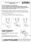
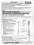
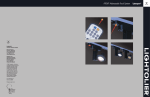
I
(
INSTRUCTION
INSTRUCTIONS
FOR LYTESPAN ATTACHMENT
lS:7589AZ
FITTING
ROW
/-
A.
CORD PENDANT MOUNTING
(supports up to 10 Ibs.)
I.
2.
Unscrew LEVER. Remove
INSERT from attachment
See “WIRING
‘RASSCoNTACT
----kc
PROCEDURE”
B. STEM MOUNTING USING
(supports up to 25 Ibs.)
1/2”
4.
See “WIRING
PROCEDURE’’
c. CHAIN MOUNTING
(supports up to 25 Ibs..)
1. Unscrew LEVER and STRAIN
Remove PLUG ASSEMBLY,
attachment
HOUSING.
~i
\
$3W27
RELIEF CAP.
HOUSING INSERT
KNURLED
—
RING
from
SET SCREW
STRAIN
RELIEF
~
CAP
Replace STRAIN RELIEF CAP with
(not supplied).
See Fig. lB.
PROCEDURE”
/’-LEvER
below.
%-18 CHAIN
~,xTuRE
CORD
LOOP
FIG.
1
below.
D. WIRING PROCEDURE
KNURLED
CHAIN
RING
LOOP
s<
KNURLED
(by others)
1. Remove 2“ of outer insulation
2.
--=&
RING onto
Insert STEM TUBING into attachment
HOUSING and screw on LOCKNUT until secure.
Tighten KNURLED RING to lock in place.
and strip
“
CONNECTOR
‘REEN LEAD
‘ROuND
3.
required)
PLUG ASSEMBLY
1
$3
Use STEM TUBING with M-18 pipe thread
3A” long (not supplied).
Screw KNURLED
STEM TUBING.
See Fig. 1A.
(when
“~F’=
w,,,-’”
2.
See “WIRING
:::~;
,SJQ/
>;,
O.D. TUBING
CONTACT
<
f
!
GROUND
LEAD
Unscrew LEVER, STRAIN RELIEF CAP and KNURLED
RING
Remove PLUG ASSEMBLY,
HOUSING INSERT
from attachment
HOUSING.
3.
GREEN
below.
I.
2.
SILVERED
‘“~
PLUG ASSEMBLY,
HOUSING
HOUSING.
See Fig. 1.
SHEET NO
from
conductor
FIXTURE CORD
ends 3A”. See Fig. 1.
Insert FIXTURE CORD through attachment
housing.
Fasten BLACK WIRE to LONGER (BRASS) CONTACT and
WHITE WIRE to SHORTER (SILVERED) contact.
For
3 conductor
cord, splice GROUND LEADS with wire
connector.
(If the GROUND LEAD from the attachment
HOUSING is not used, leave wire connector
on.) See Fig. t
*
~
sT~~
TUBING
8
STEM
CHAIN
MOUNTING
MOUNTING
CAUTION: OBSERVE POLARITY WHEN
FASTENING WIRES. BEND WIRES AROUND
SCREW IN CLOCKWISE DIRECTION.
GROOVE
3.
4.
Pull FIXTURE CORD back through attachment HOUSING and
push HOUSING INSERT and PLUG ASSEMBLY into
HOUSING (silvered contact in PLUG ASSEMBLY facing
grooved side of attachment HOUSING). Push ground leads
into area between SPRING section. Fig. 2.
LEVER
Allow fixture cord to extend into attachment HOUSING by
1/6” and tighten PLASTIC SET SCREW, Fig. 2.
TIC SET
CAUTION: TIGHTEN ENOUGH TO SUPPORT
ASSEMBLY.
FIXTURE
CORD
--’4 l\
~ ~
SCREW
>
STRAIN
RELIEF
CAP
5.
Screw LEVER into PLUG ASSEMBLY.
FIG. 2
‘@ SECAUCUS,
[m[<>[=[~<>[ml[~l~
MONTREAL,
NEW
JERSEY,
QUEBEC,
07096
”0508
CANAD~
~$js~RucT[~Ns
ATTACHMENT
FOR ATTACHING
LyTEspA/IJ
FITTING
1. Align BEAD on LYTESPAN TRACK and GROOVE
in attachment
FITTING before inserting
into
LYTESPAN TRACK.
See Fig.1 (If BEAD is NOT
aligned, a potential
hazard may result.)
2. Unscrew
position
the TURN KNOB
LEVER as shown
_
partially
and
in Fig. 1.
LYTESPAN
TRACK
BEAO
3. To attach attachment
FITTING:
squeeze BUTTON and TURN KNOB,
insert into LYTESPAN TRACK, and
release.
Tighten TURN KNOB. This
holds attachment
FITTING to LYTESPAN
TRACK mechanically.
Turn LEVER to make
electrical
connection.
See Fig. 2.
ER
BUTTON
GROOVE
NG
FIG. 1
4. To shift fixture location on the LYTESPAN
TRACK loosen TURN KNOB slightly,
release
LEVER and slide to new position.
I
5. To remove fixture reverse the procedure
in (3),
push TURN KNOB in and allow attachment
FITTING to disengage.
(
BUTTON
6.
~
Fixture can be left on LYTESPAN TRACK
when not in use by turning LEVER to
disconnect
electrically.
FIG.
2
INSTRUCTIONS
FOR CONVERTING LYTESPAN
ATTACHMENT FITTING TO OPERATE ON (2 CIRCUIT)
LYTESPAN TRACK.
BLACK
MOVABLE
NOTE:
SPACER
BRASS
CONTACT
To insure
proper operation
of Lytespots
on Two Circuit
Lytespan Track, the BLACK SPACER
(supplied) must be used at all times on the PIU9
assembly.
The BLACK
Lytespots
o
SPACER
on Single
LOWER CIRCUIT,
is not used when operating
Circuit
Track.
FIG. 3:
Illustrates
contacts
in low position
in place for lower circuit.
FIG. 3
with
spacer
MOVABLE
BRASS
CONTACT
STATIONARY
UPPER CIRCUIT,
FIG. 4 and 5:
To convert attachment
fitting for upper circuit,
raise BRASS CONTACT to high position (as
indicated
by dotted line) by pulling CONTACT
as high as stop permits and slipping
on BLACK
SPACER as shown in Fig. 4 and 5.
CONTACT
BLACK
BLACK
SPACER
SPACER
PLUG
.
b
SILVEREO
(COMMGN)
-5””
%
ASSEMBLY
0
\
II
6
FIG. 4
FIG. 5