Transcript
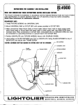
.
INSTRUCTIONSHEETNO.
INSTRUCTIONS
FIXTURES
READ AND
COVERED
FOR ASSEMBLY AND
BY THIS INSTRUCTION
UNDERSTAND
THESE
INSTALLATION
SHEET 4170&
INSTRUCTIONS
BEFORE
4171
IS:4170
osa9
INSTALLING
FIXTURE.
This fixture is intended for installation
in accordance with the National Electrical Code and local regulations.
To assure full compliance with local codes and regulations, check with your local electrical inspector before
installation. To prsvent electrical shock, turn off electricity at fuse box before proceeding.
Retain these instructions for maintenance
reference.
1. Thread MOUNTING STUDS into CROSSBAR.
Attach CROSSBAR to OUTLET BOX with
OUTLET BOX SCREWS.
(-r+rn~””’’m’”x
2. Make connections
Black fixture lead or fixture
lead without tracer mark to black supply lead;
white fixture lead or fixture lead with tracer
mark to white supply lead. Uninsulated wire is
a GROUND WIRE and must be attached to
ground terminal or GROUND WIRE in OUTLET
BOX. Use WIRE NUTS (local hardware item).
Place connections
in OUTLET BOX.
3. Place CANOPY SUB-ASSEMBLY
MOUNTING STUDS and tighten
SCREWS.
4. Install recommended
“0”””
“RE~-
-
over
with CAP
lamps.
5. Attach GLASS SHADE by looping
HARPS carefully over MOUNTING
(Fig, 2).
WIRE
HOOKS
I
STUD (Fig. 2).
WIRE HARP (2)
FIG.
GLASS SHADE ~
\
\
FIG. 2
/0?
LEVELING KNOB
LEVELING STUD
!
MOUNTING HOOK
‘ \wlREHARp
//
1