Transcript
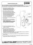
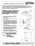
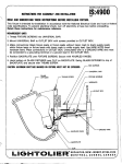
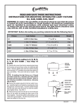
INSTRUCTIONSHEETNO.
INSTRUCTIONS
EAD
AND
FOR ASSEMBLING
UNDERSTAND
THESE
AND
INSTALLING
INSTRUCTIONS
IS:6582
FIXTURE
BEFORE
\
R1286m
lNSTALLIN~
FIXTURE.
his fixture is intended
for installation
in accordance
with the National
Electrical
Code and local or
!deral code specifications.
To prevent electrical
shock, turn off electricity
at fuse box before proceeding.
etain these instructions
for maintenance
reference.
ACCORDANCE WITH UNDERWRITERS
LABORATORIES
REQUIREMENTS,
A LINE OF
CAULKING COMPOUND SUCH AS ACRYLIC
LATEX OR BUTYL MUST BE PLACED AROUND
THE BACK OF THE FIXTURE, AROUND THE
GASKET IN ORDER TO SEAL OUT WATER.
=
‘0
Disassemble
fixture by removing LATCH” SCREW
visible at bottom, HOUSING “hinges”
up for
removal. See Fig. 2.
Attach CROSSBAR
SCREWS.
to OUTLET
BOX with
BOX
Make connections
Black fixture lead or fixture
lead without tracer mark to black supply lead;
white fixture lead or fixture lead with tracer mark
towhite
eupplylead.
Attach bare GROUND WIRE
to outlet box grounding screw (ortoothersyetem
round). Use WIRE NUTS (local hardware item).
~lace connections
in OUTLET BOX, See Fig. 1.
FIG. 1
Secure FIXTURE BODY to OUTLET BOX by placing
FIXTURE BODY over NIPPLE and threading KNOB
tight againat FIXTURE BODY. See Fig. 1.
FIXTURE must be mounted eo that SOCKET is at
bottom of FIXTURE.
Mount diffuser HOUSING to FIXTURE BODY by
tilting HOUSING to engage LUG into SLOT of
FIXTURE
BODY. Swing HOUSING
into position,
seating
againet
GASKET.
See Fig. 2.
LUG
SLOT
Preee HOUSING
into alignment
against GASKET
and secure with LATCH SCREW.
See Fig, 2.
NOTE
Mount with LATCH SCREW.
NOTE Allen-hesd set screw supplied in psrts
bsg csn be used to mskeffxturetsmper.
resistent by repleclng LATCH SCREW in fixture.
BACK.
PLATE
;AUTION:
MAXIMUM WAlTAGE AS MARKED ON
FIXIIJRE MUST N~ BE EXCEEDED.
HOUSING
LATCH SCREW
~~
FIG. 2
lmlc31=lTc>lmBB
[~BSECAUCfJS,
*
MO NT
REAL,
NEW JERSEY,07094-0508
QUEBEC,
C AN ADA
—
.-—