1
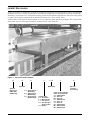
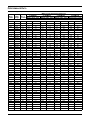
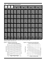
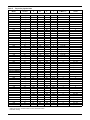
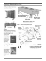
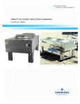
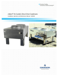
HEAT REMOVAL /ENVIRONMENTAL CONTROL
Drycoolers - 60 Hz
GENERAL DATA
TABLE OF CONTENTS
LIEBERT DRYCOOLERS . . . . . . . . . . . . . . . . . . . . . . . . . . . . . . . . . . . . . . . . . . . . . . . . . . . . . . . . .1
FEATURES AND BENEFITS OF LIEBERT DRYCOOLERS . . . . . . . . . . . . . . . . . . . . . . . . . . . . . . . . . . .2
SELECTION PROCEDURE . . . . . . . . . . . . . . . . . . . . . . . . . . . . . . . . . . . . . . . . . . . . . . . . . . . . . . . .3
PERFORMANCE DATA . . . . . . . . . . . . . . . . . . . . . . . . . . . . . . . . . . . . . . . . . . . . . . . . . . . . . . . . . .4
DIMENSIONAL DATA . . . . . . . . . . . . . . . . . . . . . . . . . . . . . . . . . . . . . . . . . . . . . . . . . . . . . . . . . . .6
ELECTRICAL DATA . . . . . . . . . . . . . . . . . . . . . . . . . . . . . . . . . . . . . . . . . . . . . . . . . . . . . . . . . . . .8
GUIDE SPECIFICATIONS . . . . . . . . . . . . . . . . . . . . . . . . . . . . . . . . . . . . . . . . . . . . . . . . . . . . . . . .10
Standard Features for Direct Drive Propeller Fan Drycoolers . . . . . . . . . . . . . . . . . . . . . . . . . . . . . 10
General. . . . . . . . . . . . . . . . . . . . . . . . . . . . . . . . . . . . . . . . . . . . . . . . . . . . . . . . . . . . . . . . . . . . . . . . . . .
Coil . . . . . . . . . . . . . . . . . . . . . . . . . . . . . . . . . . . . . . . . . . . . . . . . . . . . . . . . . . . . . . . . . . . . . . . . . . . . . .
Casing. . . . . . . . . . . . . . . . . . . . . . . . . . . . . . . . . . . . . . . . . . . . . . . . . . . . . . . . . . . . . . . . . . . . . . . . . . . .
Fans . . . . . . . . . . . . . . . . . . . . . . . . . . . . . . . . . . . . . . . . . . . . . . . . . . . . . . . . . . . . . . . . . . . . . . . . . . . . .
Fan Motors . . . . . . . . . . . . . . . . . . . . . . . . . . . . . . . . . . . . . . . . . . . . . . . . . . . . . . . . . . . . . . . . . . . . . . . .
Electrical Control. . . . . . . . . . . . . . . . . . . . . . . . . . . . . . . . . . . . . . . . . . . . . . . . . . . . . . . . . . . . . . . . . . .
10
10
10
10
10
10
COMPONENT ASSEMBLY/INSTALLATION . . . . . . . . . . . . . . . . . . . . . . . . . . . . . . . . . . . . . . . . . . . . 11
APPLICATION/INSTALLATION GUIDELINES . . . . . . . . . . . . . . . . . . . . . . . . . . . . . . . . . . . . . . . . . . . 12
Location Guidelines . . . . . . . . . . . . . . . . . . . . . . . . . . . . . . . . . . . . . . . . . . . . . . . . . . . . . . . . . . . . . . . 12
Drycooler Installation . . . . . . . . . . . . . . . . . . . . . . . . . . . . . . . . . . . . . . . . . . . . . . . . . . . . . . . . . . . . . 12
Electrical Requirements of the Drycooler . . . . . . . . . . . . . . . . . . . . . . . . . . . . . . . . . . . . . . . . . . . . . . 12
Glycol/Inhibitor Solution . . . . . . . . . . . . . . . . . . . . . . . . . . . . . . . . . . . . . . . . . . . . . . . . . . . . . . . . . . . 12
Piping Considerations . . . . . . . . . . . . . . . . . . . . . . . . . . . . . . . . . . . . . . . . . . . . . . . . . . . . . . . . . . . . . 12
PUMP PACKAGES & EXPANSION TANK - OPTIONS . . . . . . . . . . . . . . . . . . . . . . . . . . . . . . . . . . . . 13
SUPPLEMENTARY APPLICATION DATA . . . . . . . . . . . . . . . . . . . . . . . . . . . . . . . . . . . . . . . . . . . . .14
MAINTENANCE GUIDELINES . . . . . . . . . . . . . . . . . . . . . . . . . . . . . . . . . . . . . . . . . . . . . . . . . . . . . 14
i
Figures
Figure 1
Figure 2
Figure 3
Figure 4
Figure 5
Figure 6
Figure 7
Figure 8
Figure 9
Figure 10
Figure 11
Drycooler model numbers . . . . . . . . . . . . . . . . . . . . . . . . . . . . . . . . . . . . . . . . . . . . . . . . . . . . . . . . . . 1
Capacity correction factor. . . . . . . . . . . . . . . . . . . . . . . . . . . . . . . . . . . . . . . . . . . . . . . . . . . . . . . . . . 5
Pressure drop correction factor . . . . . . . . . . . . . . . . . . . . . . . . . . . . . . . . . . . . . . . . . . . . . . . . . . . . . 5
Dimensional data—1-4 fan models . . . . . . . . . . . . . . . . . . . . . . . . . . . . . . . . . . . . . . . . . . . . . . . . . . 6
Dimensional data—6 & 8 fan models. . . . . . . . . . . . . . . . . . . . . . . . . . . . . . . . . . . . . . . . . . . . . . . . . 6
Typical footprint and unit anchor plan . . . . . . . . . . . . . . . . . . . . . . . . . . . . . . . . . . . . . . . . . . . . . . . 6
General arrangement diagram. . . . . . . . . . . . . . . . . . . . . . . . . . . . . . . . . . . . . . . . . . . . . . . . . . . . . 11
Pump package . . . . . . . . . . . . . . . . . . . . . . . . . . . . . . . . . . . . . . . . . . . . . . . . . . . . . . . . . . . . . . . . . . 13
Pump mounting. . . . . . . . . . . . . . . . . . . . . . . . . . . . . . . . . . . . . . . . . . . . . . . . . . . . . . . . . . . . . . . . . 13
Expansion tank . . . . . . . . . . . . . . . . . . . . . . . . . . . . . . . . . . . . . . . . . . . . . . . . . . . . . . . . . . . . . . . . . 13
Pump curve, 60 Hz . . . . . . . . . . . . . . . . . . . . . . . . . . . . . . . . . . . . . . . . . . . . . . . . . . . . . . . . . . . . . . 13
Tables
Table 1
Table 2
Table 3
Table 4
Table 5
Table 6
Table 7
Table 8
Table 9
Table 10
Table 11
Drycooler performance data . . . . . . . . . . . . . . . . . . . . . . . . . . . . . . . . . . . . . . . . . . . . . . . . . . . . . . . . 2
Determining actual BTUH and MBH . . . . . . . . . . . . . . . . . . . . . . . . . . . . . . . . . . . . . . . . . . . . . . . . 3
Altitude correction . . . . . . . . . . . . . . . . . . . . . . . . . . . . . . . . . . . . . . . . . . . . . . . . . . . . . . . . . . . . . . . 3
Drycooler performance data . . . . . . . . . . . . . . . . . . . . . . . . . . . . . . . . . . . . . . . . . . . . . . . . . . . . . . . . 4
Drycooler physical data . . . . . . . . . . . . . . . . . . . . . . . . . . . . . . . . . . . . . . . . . . . . . . . . . . . . . . . . . . . 7
Drycooler electrical data . . . . . . . . . . . . . . . . . . . . . . . . . . . . . . . . . . . . . . . . . . . . . . . . . . . . . . . . . . . 8
Drycooler electrical data—Quietline models . . . . . . . . . . . . . . . . . . . . . . . . . . . . . . . . . . . . . . . . . . . 9
Pump data . . . . . . . . . . . . . . . . . . . . . . . . . . . . . . . . . . . . . . . . . . . . . . . . . . . . . . . . . . . . . . . . . . . . . 13
Room dew point temperatures . . . . . . . . . . . . . . . . . . . . . . . . . . . . . . . . . . . . . . . . . . . . . . . . . . . . . 14
Glycol concentration at various ambients . . . . . . . . . . . . . . . . . . . . . . . . . . . . . . . . . . . . . . . . . . . . 14
Volume in standard tube . . . . . . . . . . . . . . . . . . . . . . . . . . . . . . . . . . . . . . . . . . . . . . . . . . . . . . . . . 14
ii
LIEBERT DRYCOOLERS
Liebert drycoolers are designed to be used in conjunction with water cooled refrigeration and air conditioning
machines as well as a variety of commercial and industrial applications requiring the rejection of heat from
machinery or processes via a cooling fluid. During periods of low ambient temperatures, drycoolers may assist
or replace the capacity requirements of mechanical chillers for a “free cooling” effect.
Liebert offers a full range of control options as well as expansion tank and pump packages. For cooling fluids
other than water or water/glycol mixtures, contact Liebert, Heat Transfer.
Figure 1
Drycooler model numbers
D
D
N
C
1 0 9
Model Size
Drycooler
Optional
Disconnect
(DNC, DNL,
& DNT only)
N = Single Circuit
(No Pump)
S = Single Circuit
(With Pump)
D = Single Circuit
(Dual Pumps)
Y
Control Code:
C = No Control
L = Main Control
T = Fan Cycling
O = Fan Cycling &
Pump Control
S = Special
1
Letter Code for Voltage,
Phase and Frequency:
Y = 208/230-3-60
A = 460-3-60
B = 575-3-60
P = 208/230-1-60
Z = 460-1-60
V = 575-1-60
N = 200/230-3-50
M = 380/415-3-50
W = 200/230-1-50
D
Optional
Circuiting
(see Table 4)
FEATURES AND BENEFITS OF LIEBERT DRYCOOLERS
Heat Rejection Module
The low-profile direct-drive propeller-fan type drycoolers utilize optimum circuitry to balance the heat rejection of the corresponding load. Constructed of aluminum with a copper-tube aluminum coil, the unit is quiet
and corrosion resistant.
Low Noise Level
All Liebert drycoolers are designed to operate at a minimal noise level. This is accomplished as the result of
the Liebert fan blade design combined with a cabinet structure that minimizes air resistance. Quiet-Line
models use low speed motors to achieve the quietest unit available.
Easy Installation and Service
The heat rejection module is quickly and easily installed, because all internal wiring is completed at the factory with only electrical connections to be made at the job site.
Maximum Reliability
Because these units are factory wired and tested, start-up problems are eliminated, and reliability of the
overall system is greatly increased.
Table 1
Drycooler performance data
Model
Total
Number
Heat Rej.
*D**
@ 25 ITD
Standard Models
033
069
092
109
112
139
174
197
225
260
310
350
352
419
466
491
620
650
700
790
880
940
37950
67040
92380
108760
118200
134100
173400
197000
231000
260200
310500
353000
328400
393600
441200
469100
621000
652100
706100
787200
882000
938200
Standard Unit Data
Flow
Press.
Rate
Drop
(gpm)
(Ft. Water)
#
Internal
Circuits
Conn. +
Size
In/Out
#
26"
Fans
Air
Flow
(CFM)
dBA**
Internal
Volume
(gal.)
Shipping
Weight
(lbs.)
10
20
30
40
40
40
40
40
65
60
80
80
60
80
100
120
160
130
160
160
200
240
9.1
8.9
8.6
8.1
10.1
7.1
10.5
13.9
10.9
10.1
9.8
14.6
12.9
12.7
12.7
12.8
9.8
15.2
14.6
12.7
12.7
12.5
4
8
12
16
16
16
16
16
26
24
32
32
24
32
40
48
64
52
64
64
80
96
3/4
1-1/4
1-1/2
2
2
2
2
2
2
2
2
2
2
2
2-1/2
2-1/2
2) 2-1/8
2) 2-1/8
2) 2-1/8
2) 2-1/8
4) 2-1/8
4) 2-1/8
1
1
1
1
1
2
2
2
2
3
3
3
4
4
4
4
6
6
6
8
8
8
7200
6870
6600
6300
6090
13700
13300
12645
12200
19900
19000
17400
24800
23650
22800
21700
37900
36500
34800
47300
45500
43400
72.5
72.5
72.5
72.5
72.5
75.5
75.5
75.5
75.5
77.3
77.3
77.3
78.5
78.5
78.5
78.5
80.3
80.3
80.3
81.5
81.5
81.5
1.2
2.4
3.7
4.9
5.8
4.8
6.9
9.0
11.1
10.0
13.1
19.4
13.1
17.4
22.0
26.3
27.0
33.1
39.3
35.0
44.4
52.6
390
410
430
450
470
565
605
645
685
826
886
946
1070
1160
1250
1340
1770
1830
1890
2320
2500
2680
20
30
40
40
40
40
60
80
80
60
80
160
160
60
240
8.8
8.6
8.1
7.0
10.4
13.7
10.0
9.7
14.5
12.9
12.5
9.8
14.6
12.6
12.4
8
12
16
16
16
16
24
32
32
24
32
64
64
64
96
1-1/4
1-1/2
2
2
2
2
2
2
2
2
2
2) 2-1/8
2) 2-1/8
2) 2-1/8
4) 2-1/8
1
1
1
2
2
2
3
3
3
4
4
6
6
8
8
3110
2990
2840
6220
5980
5680
8970
8520
7440
11680
11360
17040
14880
22720
19840
56.5
56.5
56.5
59.5
59.5
59.5
61.3
61.3
61.3
62.5
62.5
64.3
64.3
65.5
65.5
2.4
3.7
4.9
4.8
6.9
9.0
10.0
13.1
19.4
13.1
17.4
27.0
39.3
35.0
52.6
410
430
450
565
605
645
825
885
950
1070
1160
1940
2060
2550
2910
Quiet-Line Models
040
057
060
080
111
121
158
173
178
205
248
347
356
453
498
44435
57000
62790
88865
110765
120800
166150
184850
186040
218980
248420
369100
371800
496000
505230
Standard data based on 95°F EAT, 120°F EFT, 40% EG.
** Sound Level - dBA @ 5 feet.
+ Connections 2" and smaller are FPT; 2-1/8" are ID. SWEAT
2
SELECTION PROCEDURE
The MBH found should be equal to or greater than
the “required MBH /ITD.”
If the MBH is less than required, repeat from Step 2
with a larger model. You may wish to repeat from
Step 2 with a smaller model for the most economical
selection meeting the required MBH/ITD.
Pressure Drop - After selecting a model, look up
the unit pressure drop following Step 3 and 4 above.
Multiply the pressure drop found by the Figure 3
correction factor. If the product is higher than your
system design, go back to Step 2 and select a model
with more circuits. This may be the same, or larger,
unit.
Table 4 shows the performance specifications for
Liebert drycoolers using a 40% by volume ethylene
glycol solution at an average fluid temperature of
115°F with flow rates from 1.5 to 3 GPM/circuit and
at standard air (.075 lbs/ft3). Figure 2 and Figure 3
offer correction factors to Table 4 for average fluid
temperatures and glycol percentages other than
115°F and 40%. Table 3 correction factors may be
used for performance at altitudes above sea level.
For cooling applications other than shown, contact
the Liebert Heat Transfer Division.
To select a drycooler from the tables in this
bulletin, the following information must be known:
1. Fluid Flow Rate (GPM).
2. % Ethylene Glycol (% EG).
3. Design Air Temperature at the Drycooler (EAT).
4. Entering and Leaving Fluid Temperatures (EFT,
LFT) or Total Heat Rejection (BTU/HR) and one
of the Fluid Temperatures.
5. ITD (Initial Temperature Difference) = EFT EAT
From the known data, calculate the following:
• Average Fluid Temperature (AFT) = (EFT +
LFT)/2.
• Heat Rejection (BTUH) = Fluid Temp. Diff. x
GPM x BTU/GPM Factor (Table 2).
• Leaving Fluid Temperature =
EFT - BTUH
(GPM) (BTU/GPM)
• Other useful information:
Leaving Air Temp. = EAT +
Drycooler BTUH
(1.08) (Drycooler CFM)
Example
Cool 40 GPM 20% ethylene glycol and water solution
from 125(F) to 115(F). Design EAT = 95(F).
Calculate:
BTUH = (125 - 115) x (40 GPM) x (480 BTU/
GPM)
BTUH = 192,000
AFT = (125 + 115)/2 = 120(F)
From Figure 2, corr. factor for 120 AFT and
20% EG = 1.04
1. Required MBH/ITD =
192,000 BTUH
(125-95) (1000) (1.04)
2. Locate model in Table 4. Models 092 through
139 fall into the GPM range but do not have the
MBH capacity. Model 174 with 16 circuits is the
smallest model meeting both the GPM range and
MBH requirements.
3. GPM/CIR = 40 GPM/16 CIR = 2.5 GPM/CIR.
4. In Table 4, Model 174 with 16 circuits at the 2.5
GPM/CIR column provides 6.9 MBH/ITD, which
exceeds the required MBH/ ITD of 6.15.
Pressure Drop = 10.5 ft. (from Table 4) x 0.93 (from
Figure 3) = 9.8 ft. H2O.
(Leaving Air Temperature should be lower than
145°F for proper motor operation.)
Using Table 4 to select a drycooler
Calculate required MBH/ITD with corrections for
glycol % and average fluid temperature.
1. Required MBH/ITD =
BTUH
(EFT - EAT) (1000) (Fig. 1 Factor)
Table 2
2. Locate Model No. in Table 4 having a GPM
range within the required flow rate and an MBH
equal to or greater than required. This gives an
approximate size.
3. Divide the given GPM by the “No. of circuits” of
the drycooler selected. The result is “GPM/CIR”
and should be in the range of 1-1/2 to 3.
4. In Table 4, look up the model selected above and
under “GPM/CIR” find the actual MBH. You may
interpolate between columns.
% Glycol
Solution
0%
10%
20%
30%
40%
50%
BTUH/GPM
500
490
480
470
450
433
Table 3
3
Determining actual BTUH and MBH
Altitude correction
Alt. (Ft.)
0
1000 2000 5000 8000 12000 15000
Corr. Fact.
1
.979
.96
.9
.841
.762
.703
PERFORMANCE DATA
Table 4
Drycooler performance data
Model
GPM
Number Range
Standard Models
033
6-12
069
6-12
12-24
092
9-18
18-36
24-48
109
12-24
24-48
112
24-48
39-78
139
12-24
24-48
174
24-48
36-72
197
24-48
48-96
225
24-48
39-78
260
24-48
36-72
310
24-48
48-96
350
24-48
48-96
72-144
352
24-48
36-72
419
24-48
48-96
466
39-78
60-120
491
24-48
48-96
72-144
620
48-96
96-192
650
60-120
78-156
120-240
700
48-96
96-192
144-288
790
48-96
96-192
880
78-156
120-240
940
48-96
96-192
144-288
MBH/°F Initial Temperature Difference
1.5
GPM/CIR
2.0 GPM/CIR
2.5 GPM/CIR
3.0 GPM/CIR
No. of
Circuits MBH/ITD PD ft. water MBH/ITD PD ft. water MBH/ITD PD ft. water MBH/ITD PD ft. water
4*
4
8*
6
12'
16
8
16*
16*
26
8
16*
16*
24
16*
32
16
26*
16
24*
16
32*
16
32*
48
16
24*
16
32*
26
40*
16
32
48*
32
64*
40
52*
80
32
64*
96
32
64*
52
80*
32
64
96*
1.3
1.8
2.3
2.7
3.2
3.4
3.3
3.9
4.2
4.5
3.6
4.5
5.8
6.4
6.5
7.7
7.1
8.1
7.5
9.7
8.3
10.7
9.2
12.3
13.4
8.8
10.6
9.5
13.2
13.1
15.2
10.1
14.9
16.7
16.7
21.4
19.9
22.0
24.6
18.5
24.6
26.7
18.9
26.4
26.2
30.4
20.2
29.8
33.4
4.2
7.3
3.9
7.0
3.7
3.0
7.1
3.8
4.6
2.6
6.2
3.3
4.7
3.2
6.2
3.0
7.4
4.4
6.4
4.4
8.4
4.1
12.2
6.0
4.2
8.1
5.5
10.6
5.2
7.9
5.3
15.6
7.7
5.3
8.0
4.1
8.0
6.3
4.1
11.8
6.0
4.0
10.2
5.2
8.1
5.2
15.3
7.7
5.1
1.5
2.1
2.5
3.0
3.5
3.6
3.7
4.1
4.5
4.7
4.1
5.0
6.5
7.0
7.3
8.3
8.0
8.8
8.7
9.7
9.7
11.7
10.9
13.4
14.2
10.4
12.1
11.4
14.7
15.0
16.7
12.5
16.6
18.0
19.4
23.5
22.7
24.4
26.5
21.8
26.8
28.5
22.8
29.4
29.9
33.4
25.0
33.2
35.9
6.2
11.4
6.0
11.7
6.2
4.6
11.3
6.0
7.3
4.4
9.8
5.2
7.5
4.9
9.9
5.0
12.0
7.4
10.2
6.8
13.5
6.9
20.9
10.1
6.7
13.1
8.7
17.3
8.8
13.2
8.6
25.6
12.9
8.6
13.3
6.8
13.1
10.2
6.7
19.8
10.0
6.7
17.1
8.7
13.1
8.5
25.4
12.9
8.6
4
1.6
2.3
2.7
3.3
3.7
3.8
3.9
4.3
4.7
4.9
4.6
5.4
6.9
7.4
7.9
8.7
8.6
9.2
9.5
10.4
10.7
12.4
12.1
14.1
14.8
11.6
13.1
12.9
15.7
16.2
17.6
9.2
17.0
8.9
16.7
8.7
6.3
16.8
8.2
10.2
6.6
14.6
7.1
10.5
7.3
14.1
7.0
17.2
11.0
14.7
10.4
19.5
9.8
29.1
14.6
10.0
18.9
12.9
25.1
12.7
19.6
12.7
1.7
2.4
2.8
3.5
3.8
3.9
4.1
4.5
4.8
5.0
4.9
5.6
7.3
7.6
8.2
8.9
9.0
9.5
10.1
10.9
11.4
12.9
12.9
14.6
15.1
12.5
13.9
14.0
16.5
17.1
18.3
12.8
23.6
12.4
23.0
12.1
8.7
23.3
11.4
14.1
9.2
20.2
9.8
14.5
10.1
19.4
9.8
23.9
15.2
20.3
14.0
26.9
13.6
40.2
20.2
13.5
26.2
17.9
36.7
17.5
27.1
17.6
17.7
18.8
21.4
24.8
24.6
26.1
27.8
24.1
28.2
29.5
25.7
31.5
32.4
35.3
18.9
12.8
19.4
9.8
19.5
15.2
9.9
29.0
14.6
9.8
25.0
12.6
19.5
12.7
18.4
19.3
22.8
25.8
26.0
27.2
28.7
26.1
17.4
26.9
13.6
27.0
20.6
13.4
29.2
30.2
20.2
13.5
33.0
34.2
36.6
17.5
26.6
17.3
35.4
37.5
18.8
12.6
36.8
38.6
26.0
17.4
Table 4
Drycooler performance data (continued)
Model
GPM
Number Range
Quiet-Line Models
040
6-12
12-24
057
18-36
24-48
060
12-24
24-48
080
12-24
24-48
111
24-48
36-72
121
24-48
48-96
158
24-48
36-72
173
24-48
48-96
178
24-48
48-96
72-144
205
24-48
36-72
248
24-48
48-96
347
48-96
96-192
356
48-96
96-192
144-288
453
48-96
96-192
498
48-96
96-192
144-288
MBH/°F Initial Temperature Difference
1.5
GPM/CIR
2.0 GPM/CIR
2.5 GPM/CIR
3.0 GPM/CIR
No. of
Circuits MBH/ITD PD ft. water MBH/ITD PD ft. water MBH/ITD PD ft. water MBH/ITD PD ft. water
4
8*
12*
16
8
16*
8
16*
16*
24
16*
32
16
24*
16
32*
16
32*
48
16
24*
16
32*
32
64*
32
64*
96
32
64*
32
64
96*
1.4
1.6
2.1
2.2
2.2
2.4
2.7
3.2
4.4
4.2
4.4
4.8
5.6
6.0
6.1
6.9
6.5
7.1
7.3
6.9
7.8
7.6
9.1
12.2
13.8
12.9
14.2
14.6
15.2
18.2
16.1
18.8
19.5
7.4
3.9
3.6
3.0
7.1
3.8
6.2
3.3
4.7
3.2
6.1
2.9
6.4
4.3
8.4
4.1
12.3
6.0
4.1
8.2
5.5
10.7
5.2
8.0
4.1
11.9
6.0
4.0
10.3
5.2
15.4
7.7
5.1
1.5
1.7
2.2
2.3
2.3
2.5
3.0
3.4
4.3
4.4
4.7
4.9
6.0
6.4
6.6
7.2
6.9
7.3
7.4
7.7
8.4
8.5
9.6
13.2
14.4
13.8
14.7
14.9
17.0
19.2
17.8
19.5
20.0
11.4
5.9
6.1
4.6
11.3
5.9
9.8
5.1
7.4
4.8
9.7
4.9
10.3
6.7
13.5
6.8
20.0
10.0
6.6
13.2
8.7
17.4
8.7
13.3
6.7
19.8
9.9
6.6
17.2
8.7
25.6
12.8
8.5
1.6
1.8
2.3
2.3
2.4
2.5
3.2
3.6
4.4
4.6
4.8
5.0
6.3
6.6
6.9
7.4
7.1
7.4
7.5
8.2
8.8
9.1
9.9
13.9
14.8
14.3
14.9
15.0
18.1
19.9
18.8
19.9
20.2
17.0
8.9
8.6
6.2
16.6
8.1
14.5
7.0
10.4
7.2
13.7
7.0
14.7
10.0
19.5
9.7
29.1
14.5
9.9
18.9
12.9
25.2
12.5
19.4
9.7
29.0
14.4
9.6
25.1
12.5
37.6
18.6
12.4
1.7
1.8
2.3
2.4
2.5
2.5
3.3
3.7
4.5
4.6
4.9
5.1
6.6
6.8
7.1
7.5
7.3
7.5
7.6
8.6
9.0
9.4
10.1
14.3
15.0
14.5
15.0
15.2
18.9
20.3
19.2
20.1
20.4
23.5
12.3
11.9
8.6
23.0
11.3
20.1
9.7
14.3
10.0
18.9
9.6
20.3
13.8
26.9
13.5
40.1
20.0
13.3
26.2
17.6
34.8
17.3
26.8
13.4
40.0
20.0
13.3
34.7
17.3
51.8
25.7
17.2
* Standard Circuiting
Based on 40% Ethylene Glycol Solution at 115°F average solution temperature expressed in MBH.
Specifications subject to change without notice.
Figure 2
Capacity correction factor
Figure 3
Pressure drop correction factor
Glycol % and fluid temperature °F
Correction Factor
Correction Factor
Glycol % and average temperature °F
Average Fluid Temperature
Average Fluid Temperature
5
DIMENSIONAL DATA
Figure 4
Dimensional data—1-4 fan models
L
43-9/16"
(962mm)
70"
(1778mm)
Eyebolts for lifting
condenser provided on
4, 6 & 8 fan models only
37-7/8"
(962mm)
Height to top
of fan guard
43-1/8"
(1095mm)
18" (457mm)
C
43-3/16"
(1097mm)
Figure 5
Center leg provided on 4 & 8 fan models only
Dimensional data—6 & 8 fan models
L
36" (914.4mm)
clearance
recommended on
all sides for
proper operation
and component
access
87-1/8"
(2213mm)
70"
(1778mm)
37-7/8"
(962mm)
Height to top
of fan guard
43-1/8"
(1095mm)
18" (457mm)
86-3/4"
(2203mm)
C
Center leg provided on 4 & 8 fan models only
Outlet/inlet connections
Figure 6
Typical footprint and unit anchor plan
1"
(25.4mm)
1-3/4"
(44.5mm)
4-1/4"
(108mm)
1-3/4"
(44.5mm)
C
A
4-1/4"
(108mm)
1"
(25.4mm)
6
B
Table 5
Drycooler physical data
Drycooler
Model
Standard Models
-033
-069
-092
-109
-112
-139
-174
-197
-225
-260
-310
-350
-352
-419
-466
-491
-620
-620
-650
-650
-650
-700
-700
-700
-790
-790
-880
-880
-940
-940
-940
Quiet-Line Models
-040
-057
-060
-080
-111
-121
-158
-173
-178
-205
-248
-347
-356
-356
-453
-453
-498
-498
-498
Circuits
A
B
C
L
#Fans
& Motors**
Conn FNPT
In/Out
any
any
any
any
any
any
any
any
any
any
any
any
any
any
any
any
641
32
80
521
40
96
641
32
641
32
801
52
961
64
32
42
42
42
42
42
82
82
82
82
122
122
122
82
82
82
82
122
122
122
122
122
122
122
122
82
82
82
82
82
82
82
80
80
80
80
124
124
124
124
124
124
124
124
80
80
80
80
80
80
80
44
44
44
44
44
84
84
84
84
124
124
124
164
164
164
164
131.5
131.5
131.5
131.5
131.5
131.5
131.5
131.5
164
164
164
164
164
164
164
51.5
51.5
51.5
51.5
51.5
91.5
91.5
91.5
91.5
131.5
131.5
131.5
171.5
171.5
171.5
171.5
6
6
6
6
6
6
6
6
171.5
171.5
171.5
171.5
171.5
171.5
171.5
1
1
1
1
1
2
2
2
2
3
3
3
4
4
4
4
2) 2-1/8*
2) 2-1/8*
4) 2-1/8*
2) 2-1/8*
2) 2-1/8*
4) 2-1/8*
2) 2-1/8*
2) 2-1/8*
8
8
8
8
8
8
8
3/4
1-1/4
1-1/2
2
2
2
2
2
2
2
2
2
2
2
2-1/2
2-1/2
any
any
any
any
any
any
any
any
any
any
any
any
641
32
641
32
961
64
32
42
42
42
82
82
82
122
122
122
82
82
122
122
122
82
82
82
82
82
80
80
80
80
80
80
80
44
44
44
84
84
84
124
124
124
164
164
124
124
124
164
164
164
164
164
51.5
51.5
51.5
91.5
91.5
91.5
131.5
131.5
131.5
171.5
171.5
131.5
131.5
131.5
171.5
171.5
171.5
171.5
171.5
1
1
1
2
2
2
3
3
3
4
4
6
6
6
8
8
8
8
8
* Connections are ODS
** Motors are 3/4 HP - standard models; 1/4 HP - Quiet-Line models
1. Standard circuiting
7
2) 2-1/8*
2) 2-1/8*
4) 2-1/8*
2) 2-1/8*
4) 2-1/8*
2) 2-1/8*
2) 2-1/8*
1-1/4
1-1/2
2
2
2
2
2
2
2
2
2) 2-1/8*
2) 2-1/8*
2) 2-1/8*
2) 2-1/8*
2) 2-1/8*
4) 2-1/8*
2) 2-1/8*
2) 2-1/8*
ELECTRICAL DATA
Table 6
Drycooler electrical data
# of
Fans
1
Model
#
33,69,92,109,112
2
3
4
6
8
139,174,197,225
260,310,350
352,419,466,491
620,650,700
790,880,940
Pump
Hp ph FLA WSA OPD ph FLA WSA OPD ph FLA WSA OPD ph FLA WSA OPD ph FLA WSA OPD ph FLA WSA OPD
208/230/60
0.75
1 11.6 13.5 20.0
-
0.75
3
15.0
3 10.5 11.4 15.0
3 14.0 14.9 15.0
3 17.5 18.4 20.0
3 24.5 25.4 25.0
3 31.5 32.4 35.0
1.5
3 10.1 11.8 15.0
3 13.6 15.3 20.0
3 17.1 18.8 25.0
3 20.6 22.3 25.0
3 27.6 29.3 35.0
3 34.6 36.3 40.0
2.0
3 11.0 12.9 20.0
3 14.5 16.4 20.0
3 18.0 19.9 25.0
3 21.5 23.4 30.0
3 28.5 30.4 35.0
3 35.5 37.4 40.0
3.0
3 14.1 16.8 25.0
3 17.6 20.3 30.0
3 21.1 23.8 30.0
3 24.6 27.3 35.0
3 31.6 34.3 40.0
3 38.6 41.3 50.0
5.0
3 20.2 24.4 40.0
3 23.7 27.9 40.0
3 27.2 31.4 45.0
3 30.7 34.9 50.0
3 37.7 41.9 50.0
3 44.7 48.9 60.0
7.0
7.9
-
-
-
-
-
-
-
-
-
-
-
-
-
-
-
-
-
-
-
7.5
3 27.7 33.8 50.0
3 31.2 37.3 60.0
3 34.7 40.8 60.0
3 38.2 44.3 60.0
3 45.2 51.3 70.0
3 52.2 58.3 80.0
10.0
3 34.3 42.0 70.0
3 37.8 45.5 70.0
3 41.3 49.0 70.0
3 44.8 52.5 80.0
3 51.8 59.5 90.0
3 58.8 66.5 90.0
15
3 49.7 61.3 100.0 3 53.2 64.8 110.0 3 56.7 68.3 110.0 3 60.2 71.8 110.0 3 67.2 78.8 110.0 3 74.2 85.8 125.0
460/3/60
0.75
3
3.3
3.7
15.0
3
5.0
5.4
15.0
3
6.7
7.1
15.0
3
8.4
8.8
15.0
3 11.8 12.2 15.0
3 15.2 15.6 15.0
1.5
3
4.7
5.5
15.0
3
6.4
7.2
15.0
3
8.1
8.9
15.0
3
9.8
10.6 15.0
3 13.2 14.0 15.0
3 16.6 17.4 20.0
2.0
3
5.1
6.0
15.0
3
6.8
7.7
15.0
3
8.5
9.4
15.0
3 10.2 11.1 15.0
3 13.6 14.5 15.0
3 17.0 17.9 20.0
3.0
3
6.5
7.7
15.0
3
8.2
9.4
15.0
3
9.9 11.1 15.0
3 11.6 12.8 15.0
3 15.0 16.2 20.0
3 18.4 19.6 20.0
5.0
3
9.3
11.2 15.0
3 11.0 12.9 20.0
3 12.7 14.6 20.0
3 14.4 16.3 20.0
3 17.8 19.7 25.0
3 21.2 23.1 30.0
7.5
3 12.7 15.5 25.0
3 14.4 17.2 25.0
3 16.1 18.9 25.0
3 17.8 20.6 30.0
3 21.2 24.0 30.0
3 24.6 27.4 35.0
10.0
3 15.7 19.2 30.0
3 17.4 20.9 30.0
3 19.1 22.6 35.0
3 20.8 24.3 35.0
3 24.2 27.7 40.0
3 27.6 31.1 45.0
15
3 22.7 28.0 45.0
3 24.4 29.7 50.0
3 26.1 31.4 50.0
3 27.8 33.1 50.0
3 31.2 36.5 50.0
3 34.6 39.9 60.0
575/3/60
0.75
3
2.7
3.1
15.0
3
4.1
4.5
15.0
3
5.5
5.9
15.0
3
6.9
7.3
15.0
3
10.1 15.0
3 12.5 12.9 15.0
1.5
3
3.8
4.4
15.0
3
5.2
5.8
15.0
3
6.6
7.2
15.0
3
8.0
8.6
15.0
3 10.8 11.4 15.0
3 13.6 14.2 15.0
2.0
3
4.1
4.8
15.0
3
5.5
6.2
15.0
3
6.9
7.6
15.0
3
8.3
9.0
15.0
3 11.1 11.8 15.0
3 13.9 14.6 15.0
3.0
3
5.3
6.3
15.0
3
6.7
7.7
15.0
3
8.1
9.1
15.0
3
9.5
10.5 15.0
3 12.3 13.3 15.0
3 15.1 16.1 15.0
5.0
3
7.5
9.0
15.0
3
8.9 10.4 15.0
3 10.3 11.8 15.0
3 11.7 13.2 15.0
3 14.5 16.0 20.0
3 17.3 18.8 20.0
7.5
3 10.4 12.7 20.0
3 11.8 14.1 20.0
3 13.2 15.5 20.0
3 14.6 16.9 25.0
3 17.4 19.7 25.0
3 20.2 22.5 30.0
10.0
3 12.4 15.2 25.0
3 13.8 16.6 25.0
3 15.2 18.0 25.0
3 16.6 19.4 30.0
3 19.4 22.2 30.0
3 22.2 25.0 35.0
15
3 18.4 22.7 35.0
3 19.8 24.1 40.0
3 21.2 25.5 40.0
3 22.6 26.9 40.0
3 25.4 29.7 45.0
3 28.2 32.5 45.0
8
9.7
Table 7
Drycooler electrical data—Quietline models
# of
Fans
1
2
3
4
6
8
Model
#
40,57,60
80,111,121
158,173,178
205,248
347,356
453,498
Pump
Hp ph FLA WSA OPD ph FLA WSA OPD ph FLA WSA OPD ph FLA WSA OPD ph FLA WSA OPD ph FLA WSA OPD
208/230/60
0.75
3
5.3
6.2
1.5
3
8.4
10.1 15.0
2.0
3
9.3
11.2 15.0
3 11.1 13.0 20.0
3 12.9 14.8 20.0
3 14.7 16.6 20.0
3 18.3 20.2 25.0
3 21.9 23.8 30.0
3.0
3 12.4 15.1 25.0
3 14.2 16.9 25.0
3 16.0 18.7 25.0
3 17.8 20.5 30.0
3 21.4 24.1 30.0
3 25.0 27.7 35.0
5.0
3 18.5 22.7 35.0
3 20.3 24.5 40.0
3 22.1 26.3 40.0
3 23.9 28.1 40.0
3 27.5 31.7 45.0
3 31.1 35.3 50.0
7.5
3 26.0 32.1 50.0
3 27.8 33.9 50.0
3 29.6 35.7 50.0
3 31.4 37.5 60.0
3 35.0 41.1 60.0
3 38.6 44.7 60.0
10.0
3 32.6 40.3 70.0
3 34.4 42.1 70.0
3 36.2 43.9 70.0
3 38.0 45.7 70.0
3 41.6 49.3 80.0
3 45.2 52.9 80.0
15
15.0
3
7.1
8.0
15.0
3 10.2 11.9 15.0
15.0
3 10.7 11.6 15.0
3 14.3 15.2 15.0
3 17.9 18.8 20.0
3 12.0 13.7 20.0
3
8.9
9.8
3 13.8 15.5 20.0
3 17.4 19.1 25.0
3 21.0 22.7 25.0
3 48.0 59.6 100.0 3 49.8 61.4 100.0 3 51.6 63.2 100.0 3 53.4 65.0 110.0 3 57.0 68.6 110.0 3 60.6 72.2 110.0
460/3/60
0.75
3
2.5
2.9
15.0
3
3.4
3.8
15.0
3
4.3
4.7
15.0
3
5.2
5.6
15.0
3
7.0
7.4
15.0
3
1.5
3
3.9
4.7
15.0
3
4.8
5.6
15.0
3
5.7
6.5
15.0
3
6.6
7.4
15.0
3
8.4
9.2
15.0
3 10.2 11.0 15.0
8.8
9.2
15.0
2.0
3
4.3
5.2
15.0
3
5.2
6.1
15.0
3
6.1
7.0
15.0
3
7.0
7.9
15.0
3
8.8
9.7
15.0
3 10.6 11.5 15.0
3.0
3
5.7
6.9
15.0
3
6.6
7.8
15.0
3
7.5
8.7
15.0
3
8.4
9.6
15.0
3 10.2 11.4 15.0
3 12.0 13.2 15.0
5.0
3
8.5
10.4 15.0
3
9.4 11.3 15.0
3 10.3 12.2 15.0
3 11.2 13.1 20.0
3 13.0 14.9 20.0
3 14.8 16.7 20.0
7.5
3 11.9 14.7 25.0
3 12.8 15.6 25.0
3 13.7 16.5 25.0
3 14.6 17.4 25.0
3 16.4 19.2 30.0
3 18.2 21.0 30.0
10.0
3 14.9 18.4 30.0
3 15.8 19.3 30.0
3 16.7 20.2 30.0
3 17.6 21.1 35.0
3 19.4 22.9 35.0
3 21.2 24.7 35.0
15
3 21.9 27.2 45.0
3 22.8 28.1 45.0
3 23.7 29.0 45.0
3 24.6 29.9 50.0
3 26.4 31.7 50.0
3 28.2 33.5 50.0
575/3/60
0.75
3
2.0
2.3
15.0
3
2.7
3.0
15.0
3
3.4
3.7
15.0
3
4.1
4.4
15.0
3
5.5
5.8
15.0
3
6.9
7.2
15.0
1.5
3
3.1
3.7
15.0
3
3.8
4.4
15.0
3
4.5
5.1
15.0
3
5.2
5.8
15.0
3
6.6
7.2
15.0
3
8.0
8.6
15.0
2.0
3
3.4
4.1
15.0
3
4.1
4.8
15.0
3
4.8
5.5
15.0
3
5.5
6.2
15.0
3
6.9
7.6
15.0
3
8.3
9.0
15.0
3.0
3
4.6
5.6
15.0
3
5.3
6.3
15.0
3
6.0
7.0
15.0
3
6.7
7.7
15.0
3
8.1
9.1
15.0
3
9.5
10.5 15.0
5.0
3
6.8
8.3
15.0
3
7.5
9.0
15.0
3
8.2
9.7
15.0
3
8.9
10.4 15.0
3 10.3 11.8 15.0
3 11.7 13.2 15.0
7.5
3
9.7
12.0 20.0
3 10.4 12.7 20.0
3 11.1 13.4 20.0
3 11.8 14.1 20.0
3 13.2 15.5 20.0
3 14.6 16.9 25.0
10.0
3 11.7 14.5 25.0
3 12.4 15.2 25.0
3 13.1 15.9 25.0
3 13.8 16.6 25.0
3 15.2 18.0 25.0
3 16.6 19.4 30.0
15
3 17.7 22.0 35.0
3 18.4 22.7 35.0
3 19.1 23.4 40.0
3 19.8 24.1 40.0
3 21.2 25.5 40.0
3 22.6 26.9 40.0
9
GUIDE SPECIFICATIONS
Standard Features for Direct
Drive Propeller Fan
Drycoolers
Furnish and install Liebert Model
________ Air-Cooled Drycoolers,
arranged for vertical air flow. Drycoolers shall be draw-through
design and shall perform in accordance with the schedule.
General
Each drycooler shall consist of casing, drycooler coil, propeller fans
direct-driven by individual fan
motors, fan guards, and mounting
legs.
Fan motors shall be furnished for
operation on a _______ V, ____PH,
______ Hz power supply.
Coil
The drycooler coil shall be constructed on copper tubes on a staggered tube pattern. Tubes shall be
expanded into continuous, rippled
aluminum fins. The fins shall have
full-depth fin collars completely
covering the copper tube. Copper
tubes shall be connected to heavy
wall type “L” headers, inlet coil
connector tubes shall pass through
relieved holes in the tube sheet, for
maximum resistance to piping
strain and vibration.
Coils shall be factory leak-tested at
300 PSIG (minimum) dehydrated,
evacuated and sealed.
Casing
Quiet-Line Motors
The drycooler casing shall be constructed of bright aluminum
sheet. Casing shall be divided into
individual fan sections by full
width baffles. Structural support
members, including coil support
frame, motor and drive support
shall be galvanized steel for
strength and corrosion resistance. Aluminum legs with rigging holes shall be provided for
hoisting the unit into position.
Fan motors shall be 12-pole,
570 rpm, equipped with rain
shields and permanently sealed
ball bearings. Motors shall
include built-in overload protection. Motors shall be rigidly
mounted on die-formed galvanized steel supports.
Fans
Fans shall have zinc plated steel
or aluminum blades. Fan shall be
secured to fan shaft by means of a
heavy-duty keyed hub and dual
set screws. Fan diameter shall be
30" or less. Fans shall be factorybalanced and run before shipment.
Fan guards shall be heavy gauge,
close-meshed, steel wire, with corrosion resistant finish.
Fan Motors
Fan motors shall be equipped
with rain slingers and permanently sealed ball bearings.
Motors shall include built-in overload protection. Motors shall be
rigidly mounted on die-formed
galvanized steel supports.
Electrical Control
All electrical connections (and
electrical low ambient control
options) shall be provided in
weatherproof enclosure. The
enclose shall be integral with the
drycooler for pleasing appearance
as well as functional protection.
The base model (DNC) shall have
the motor(s) factory wired to a
three phase power block in the
electrical enclosure. Main electrical control model (DNL) provides
magnetic contactor and control
voltage for remote starting of the
drycooler.
The drycooler shall be provided
with optional disconnect switch
mounted and wired.
Fan cycling model (DNT) shall be
used to control leaving fluid temperature by cycling fans in one or
two steps. The 24 volt control circuit furnished, consists of control
transformer, fan contactor(s) and
temperature controls) as specified.
Fan cycling with pump control
model (DSO)-single pump, (DDO)dual pump shall have the features
as the fan cycling model plus
starter(s) for the pump(s) and a
built-in disconnect switch.
10
COMPONENT ASSEMBLY/INSTALLATION
Leg Assembly
The legs are shipped loose and are
to be field mounted as shown with
the hardware provided.
Secure each leg to drycooler
frame at all four points shown
using hardware provided
Outlet
Electrical service
supply by others
Inlet
Models 069-491
Models 620 through 940 have 2 sets
of connections on end of unit
Figure 7
General arrangement diagram
Fill*
Typical rigging
Rigging
Holes in the drycooler legs permit
lifting the unit. Spreader bars are
required. Four, 6 and 8 fan models
have additional lifting eyes.
High Voltage Electrical
Connections
Line Voltage is
connected to the
terminal strip
or directly to
the factory supplied locking
disconnect
(optional).
Check voltage
and compare to nameplate.
Low Voltage Electrical
Connections
A control interlock between the
indoor and outdoor equipment
must be minimum 16 ga. for
up to 75 ft. or not
to exceed 1 volt
drop in control
line.
Expansion
tank field
installed at
highest point
in system
Drycooler coil
Drycooler
electric box
Optional dual pump
system shown
Unions*
Glycol
pumps
s*
ion
Un
Pressure
port*
*
lve
va
g
xi n
Mi
Gate or ball*
valve for
isolation (typ)
Gate or ball*
valve for bypass
Hose
bib*
Pump
housing
Check valves*
on dual pump
systems only
Flow switch supplied
with dual pump systems*
Flow regulating valve*
Pressure port*
Air vents at top of risers*
Field piping
* Components are not supplied by Liebert,
and all components shown may not be
necessary for system operation.
Flow direction
11
APPLICATION/INSTALLATION GUIDELINES
Location Guidelines
To ensure an adequate air supply,
locate drycoolers in a clean air
area, away from loose dirt and foreign matter that may clog the coil.
In addition, drycoolers must not
be placed near steam, hot air, or
fume exhausts. Also, drycoolers
should be no closer than 3 feet
from a wall, obstruction or adjacent unit with no obstructions over
the unit. Install drycoolers in a
level position to assure proper vent
and drain.
All drycooler legs have mounting
holes for securing the unit to steel
supports or concrete pads.
For roof installation, mount drycoolers on steel supports in accordance with local codes. To
minimize sound and vibration
transmission, mount steel supports across load-bearing walls.
For ground installations, a concrete pad will support the load.
Drycooler Installation
The drycooler should be located
for maximum security and maintenance accessibility. Avoid
ground level sites with public
access or areas which contribute
to heavy snow or ice accumulations. Utilize centrifugal fan drycoolers when placing a drycooler
in a building.
Electrical Requirements of
the Drycooler
Electrical service is required for
all drycoolers at the location of the
outdoor system. The power supply
does not necessarily have to be the
same voltage supply as required
by the indoor unit. This separate
power supply may be 208, 230,
460 or 575 volt, 60 Hz. For electrical characteristics of the standard
voltage drycoolers, see Full Load
Amps (FLA) of the drycooler in
Tables 6 and 7 and FLA of the
pump, if used, in Table 8. Dual
element, time delay type fuses or
“HACR” circuit breakers at the
main power source. The only electrical connection between the
indoor unit and the drycooler is a
two wire control interlock which is
field-connected when provided.
Glycol/Inhibitor Solution
The percentage of glycol to water
will be determined by the outdoor
ambient in which the system is
operating. Just as critical is the
inhibitor used with the glycol.
Commercial ethylene glycol
(Union Carbide Ucartherm, Dow
Chemical Dowtherm SR-1, and
Texaco E.G. Heat Transfer Fluid
100), when pure, is generally less
corrosive to the metals than water.
It will, however, assume the corrosivity of the water from which it is
prepared and may become increasingly corrosive with use if not
properly inhibited. Proper inhibitor maintenance must be performed to prevent corrosion of the
glycol system. Consult glycol manufacturer for testing and maintenance of inhibitors.
Automotive antifreeze is unacceptable and must not be used
in any glycol fluid system.
There are two basic concepts of
corrosion inhibition: They are classified as corrosion inhibitors or
environmental stabilizers. The corrosion inhibitors function by forming a surface barrier that protects
the metals. Environmental stabilizers decrease corrosion by stabilizing or favorably altering the
overall environment. An alkaline
buffer, such as borax, is a simple
example, since its prime purpose is
to maintain an alkaline condition
(ph above 7).
The quality of the water of dilution must be considered because
water may contain corrosive elements which reduce the effectiveness of the inhibited formulation.
Surface waters that are classified
as soft and are low in chloride and
sulfate ion content (less than
100 ppm each) should be
employed.
12
Piping Considerations
CAUTION: When using water
under pressure to test the system
for leaks, immediately charge the
tested system with glycol. Complete system drain-down cannot be
assured. Replacing broken, frozen
piping is a needless exercise. A
preferred test method utilizes common refrigerant gas pressurized
with nitrogen. A refrigerant type
leak detector will find even the
smallest leak when properly used.
Galvanized pipe or other components should not be used
with an inhibited glycol system.
All fluid piping must comply
with local codes. Care in sizing
pipes will help reduce pumping
power and operating costs.
Manual shut-off valves and unions
should be installed at the supply
and return line of each major system component. This permits routine service or emergency isolation
of the component.
Where connecting to a city water
supply, provide a disconnection
means. A city water source is desirable for initially charging the system and as an emergency standby
cooling source.
The minimum glycol temperature
to be supplied from the drycooler
determines whether the supply
and return lines should be insulated to prevent condensation (see
Table 9).
Vents are required at system high
points to vent trapped air when
filling the system.
Since the system is not open to the
atmosphere, an expansion tank
must be provided for expansion
and contraction of the fluid with
temperature change. A relief
valve is also necessary.
A fill port is necessary for charging the system with glycol.
Depending on the complexity of the
system, various other devices may
be specified, such as pressure
gauges, valves, pumps and sensors.
PUMP PACKAGES & EXPANSION TANK - OPTIONS
Figure 8
Pump package
See
Note 1
Figure 10 Expansion tank
30-1/4"
(768.4mm)
Pump
discharge
connections
19"
(483mm)
Pump suction
connections
Provided on dual
pump package only
Expansion Tank- (P/N 1C16717P1)
Figure 9
Pump mounting
1/2" (12.7mm)
diameter holes
This tank, included in a standard pump package, has an internal volume of 8.8 gal. (33 l)
and a maximum pressure of 100 psi (690 kPa).
This tank is sized for a typical “open” system with a fluid volume of less than 75 gal.
(280l). When used in a “closed” system, volumes of up to 140 gal. (910l) can be accommodated. The use of a safety relief valve, field supplied, is recommended for systems
“closed” to atmospheric venting. Other piping accessories for filling, venting, or adjusting
the fluid in the system, are recommended, but not included.
Table 8
3/4"
(19.1mm)
Connections
Pump Package
Mounting
23"
(584.2mm)
3-1/2"
(88.9mm)
Notes
1. Single pump packages are
17-1/4" (438.2mm) wide. Dual
pump packages are 32-1/4"
(819.2mm) wide.
2. Mounting holes are 15-11/32"
(389.7mm) apart on single
pump packages and
30-11/32" (770.7mm) apart on
dual pump packages.
3. 7-1/2hp dimensions not
shown—consult factory.
Electric @ 60Hz
Pump
Model
NPT
Suction
Female
Discharge
HP
3/4
3/4
1-1/2
2
3
5
7-1/2
1-1/4"
1-1/4"
1-1/4"
1-1/4"
1-1/2"
1-1/2"
3"
3/4"
3/4"
3/4"
3/4"
1"
1-1/4"
3"
3/4
3/4
1-1/2
2
3
5
7-1/2
PH
208
FLA
230
FLA
460
FLA
575
FLA
1
3
3
3
3
3
3
7.6
3.5
6.6
7.5
10.6
16.7
24.2
6.9
3.2
6.0
6.8
9.6
15.2
22.0
N/A
1.6
3.0
3.4
4.8
7.6
11.0
N/A
1.3
2.4
2.7
3.9
6.1
9.0
To Calculate Total Pump and Drycooler Full Load Amps (FLA):
Total FLA = Pump FLA + Drycooler FLA
To Calculate Total Pump and Drycooler Wire Size Amps (WSA)
Total WSA = Largest Motor FLA x 1.25 + Sum of other Motor FLA values
To Calculate Total Pump and Drycooler Maximum Overcurrent Protective Device (OPD)
Total OPD = Largest Motor FLA x 4.0 + Sum of other Motor FLA values
Select standard fuse size (15A, 20A, 25A, 30A, etc.)
Figure 11 Pump curve, 60 Hz
180
160
140
Total Head - ft. water
See
Note
2
Pump data
120
100
80
60
40
20
0
10 20 30 40 50 60 70 80 120 160 200 250 300 400
Flow Rate - GPM
13
SUPPLEMENTARY APPLICATION DATA
Table 9
Room dew point temperatures
Table 11
Dry bulb
°F (°C)
Wet bulb
°F (°C)
Rel. hum.
%
Dew point*
°F (°C)
70
57.2
45
41.1
70
58.5
50
50.5
72
58.9
45
72
60.0
75
75
Type “L” copper tube
Diameter (in.)
Inside
Gal/ft
(L/m)
50.0
.50
0.430
0.0075
(0.09)
50
52.4
.625
0.545
0.0121
(0.15)
61.2
45
52.4
.75
0.666
0.0181
(0.22)
62.5
50
55.0
.875
0.785
0.0251
(0.31)
1.125
1.025
0.0429
(0.53)
1.375
1.265
0.0653
(0.81)
1.625
1.505
0.0924
(1.15)
2.125
1.985
0.161
(2.00)
2.625
2.465
0.248
(3.08)
3.125
2.945
0.354
(4.40)
3.625
3.425
0.479
(5.95)
4.125
3.905
0.622
(7.73)
Glycol concentration at various
ambients
% Glycol
by volume
0
10
20
30
40
50
Freezing
point °F
32
25
16
5
-10
-32
Apparent
specific
gravity
@50°F
Volume
Outside
* Minimum glycol temperature before condensation will occur
Table 10
Volume in standard tube
1.000
1.014
1.028
1.042
1.057
1.071
MAINTENANCE GUIDELINES
Restricted airflow through the
drycooler coil will reduce the operating efficiency of the unit and
can result in high fluid temperatures and loss of cooling.
Clean the drycooler coil of all
debris that will inhibit air flow.
This can be done with compressed
air or commercial coil cleaner.
Check for bent or damaged coil
fins and repair as necessary. In
winter, do not permit snow to
accumulate around the sides or
underneath the drycooler.
Check all fluid lines and capillaries for vibration isolation. Support
as necessary.
Visually inspect all fluid lines for
signs of fluid leaks.
Inspect the motor/fan assembly to
insure bearings are (free) and
motor is secure within the mount.
The glycol in drycooler systems
level must be periodically
checked. At the high point of the
system check:
• For positive pressure.
• For air to be vented.
• For an unlogged expansion
tank. A fluid sample for
proper concentrations of antifreeze and inhibitors.
The first three checks may give
indication of leaks in the system.
14
Important
When ordering replacement parts
for heat rejection equipment, it is
necessary to specify unit model
number - serial number - voltage.
Enter this information below for
future use.
Model No.
Serial No.
Voltage
HEAT REMOVAL /ENVIRONMENTAL CONTROL
Drycoolers - 60 Hz
GENERAL DATA
The Company Behind the Products
Technical Support
With over a million installations around the globe,
Liebert is the world leader in computer protection
systems. Since its founding in 1965, Liebert has
developed a complete range of support and
protection systems for sensitive electronics:
United States
1050 Dearborn Drive
P.O. Box 29186
Columbus, OH 43229
•
•
•
•
•
Environmental systems—close-control air
conditioning from 1 to 60 tons
Power conditioning and UPS with power
ranges from 300 VA to more than 1000 kVA
Integrated systems that provide both
environmental and power protection in a
single, flexible package
Monitoring and control—from systems of any
size or location, on-site or remote
Service and support through more than 100
service centers around the world and a 24/7
Customer Response Center
While every precaution has been taken to ensure
the accuracy and completeness of this literature,
Liebert Corporation assumes no responsibility and
disclaims all liability for damages resulting from
use of this information or for any errors or
omissions.
© 1994 Liebert Corporation
All rights reserved throughout the world.
Specifications subject to change without notice.
® Liebert and the Liebert logo are registered
trademarks of Liebert Corporation. All names
referred to are trademarks or registered
trademarks of their respective owners.
SL-10058 (10/02)
Single-Phase UPS
800-543-2378
Outside the United States
614-841-6598
3-Phase UPS
800-543-2378
Environmental Control
800-543-2778
Italy
Via Leonardo Da Vinci 8
Zona Industriale Tognana
35028 Piove Di Sacco (PD)
+39 049 9719 111
FAX: +39 049 5841 257
Asia
23F, Allied Kajima Bldg.
138 Gloucester Road
Wanchai
Hong Kong
+852 2 572 2201
FAX: +852 2 831 0114
Web Site
www.liebert.com
E-mail
[email protected]