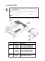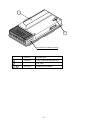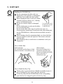
1
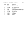
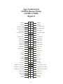
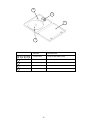
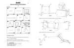
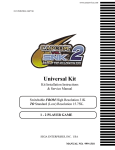
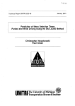
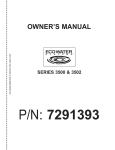
1ST PRINTING JUNE 01
Universal Kit
Kit Installation Instructions
& Service Manual
Switchable FROM High Resolution 31K
TO Standard (Low) Resolution 15.75K.
1 - 2 PLAYER GAME
SEGA ENTERPRISES, INC. USA
MANUAL NO. 999-1292
Warranty
Your new Sega Product is covered for a period of 90 days from the date of shipment. This certifies
that the Printed Circuit Boards, Power Supplies and Monitor are to be free of defects in workmanship or materials under normal operating conditions. This also certifies that all Interactive Control
Assemblies are to be free from defects in workmanship and materials under normal operating conditions. No other product in this machine is hereby covered.
Sellers sole liability in the event a warranted part described above fails shall be, at its option, to
replace or repair the defective part during the warranty period. For Warranty claims, contact your
Sega Distributor.
Should the Seller determine, by inspection that the product was caused by Accident, Misuse, Neglect, Alteration, Improper Repair, Installation or Testing, the warranty offered will be null and void.
Under no circumstances is the Seller responsible for any loss of profits, loss of use, or other damages.
This shall be the exclusive written Warranty of the original purchaser expressed in lieu of all other
warranties expressed or implied. Under no circumstance shall it extend beyond the period of time
listed above.
World Series 2001
Sega Naomi System
Kit Contains List
Part #
Desc
Qty
400-5397-01
NAOMI POWER SUPPLY
1
838-13616
AUDIO POWER AMP 2 CH
1
560-5407-UL
AUDIO XFORMER 120V
1
838-13683-93CV1
JAMMA I/O BD (NAOMI)
1
600-7141-200
USB CABLE
1
600-7009-2500
VGA VIDEO CABLE
1
840-0051D-01
ASSY CASE PC1 DIMM BD
1
600-7247-500
CABLE SCSI TYPE 2 500MM
1
LOC. PURCHASE
SERVICE SWT BRKT ASSY
1
XKT-0833
GD-ROM DRIVE KIT
1
610-0630-0010
GD SOFT KIT WS2K1
1
999-1293
MARQUEE WS2K1
1
999-1294
INST SHT AMER LG WS2K1
1
999-1295
INST SHT NAT LG WS2K1
1
999-1296
INST SHT CONTROL WS2K1
1
999-1297
SIDE DECALS WS2K1
2
NOA-20010-01
CONT PNL ASSY WS2K1
(See Breakdown Next Page.)
1
1
ASSY CTRL PNL 2A4B2S MB2K2 ENG (NOA-20010-01)
2
(D-1/2)
ASSY CTRL PNL 2A4B2S MB2K2 ENG (NOA-20010-01)
ITEM NO.
(D-2/2)
PART NO.
DESCRIPTION
1
2
HOT-2023
NOA-2025-01
CTRL PNL BASE 2A4B2S
CTRL PNL PLATE 2A4B2S ENG
101
102
103
104
105
106
107
109
610-6723-4B02
610-6723-4B01
610-0409
999-1290
999-1086
999-1289
280-5009-01
280-5275-SR10
ASSY ANALOG JOY 4B PINK
ASSY ANALOG JOY 4B GREEN
ASSY BAT MECHA
PUSHBUTTON RND YELLOW W/MICRO (2 PER)
PUSHBUTTON RND GREEN W/MICRO (2 PER)
PUSHBUTTON RND PINK W/MICRO (2 PER)
CORD CLAMP 21
CORD CLAMP SR10
201
202
203
204
050-U00400
060-F00400
060-S00400
050-H00400
U NUT M4
FLT WSHR M4
SPR WSHR M4
HEX NUT M4
3
Feb 9. 2000
SERVICE BULLETIN
SEGA Service Department
45133 Industrial Drive
Fremont, Ca. 94538
120
http://www.seuservice.com
Phone: 415.701.6580
Fax: 415.701.6594
SPECIAL NOTICE FOR
ALLSEGANAOMIKITS
PROBLEM:
The SEGA Naomi Game kits are actually ‘JAMMA Dependent’. What this means exactly is they will only
install into existing JAMMA Cabinets. If an operator tries to install these kits into a Non-JAMMA cabinet,
they will first have to bring the wiring up to JAMMA Standards.
SOLUTION:
°
°
Step 1 Disconnect the games original DC Power Supply. You may only use the power supply provided
with your kit. Be sure to set the voltages going to your Game BD to 5.1 and 3.3 volts DC to assure proper
operation ( Measure on Square Connector at Game BD. Yellow = 5vdc / Brown = 3.3vdc / White = Gnd )
Step 2 You MUST USE THE COIN METER SUPPLIED WITH YOUR KIT to assure proper Coin
acceptance. A minimum 18 Gauge wire should be used from the Coin Meter 1 output line on your
JAMMA Harness. The 5vdc ( Yellow ) wire found in the wiring bag of your kit MUST BE USED for the
supply voltage to the meter.
Not following the directions provided herein may cause your game to malfunction.
All electrical work should be performed by the site’s Serviceman or Technician.
In order to prevent an electric shock and short circuit, be sure to turn power off before performing
work or touching the interior parts of the product.
Be careful so as not to damage wirings. Damaged wiring can cause an electric shock or short circuit
accident.
Do not touch places other than those specified. Touching places not specified can cause an electric
shock or short circuit accident.
If you have any questions please contact the SEGA Service Department at the numbers given above.
4
INSTALLATION INSTRUCTIONS
1) First. Remove all access panels from the game. Locate the original game Logic PCB’s & Power
Supply and remove from the Cabinet by first disconnecting all harnesses from the boards. (You need
only to splice in the Main Power (110v AC) into the 3-Pin Connector (GRN/WHT/BLK).)
2) Remove all existing game harnesses (we suggest using New Jamma Harnesses (NOT contained in the
kit) to ensure reliability).
3) Locate the most convenient and open area of the cabinet to mount the World Series 2001 Naomi
System Assembly. Make sure this area is free and clear of all cable harnesses and grounds, cable
clamps, etc.
Vacuum out or clean bottom of cabinet of dirt & miscellaneous parts (e.g.
screws, loose coins / tokens, etc.).
Remove all exterior decals and repair any cabinet damage. Repaint
cabinet if necessary. Remove the Monitor Plexi or if your game plexi has
Silk-screened artwork, you will need to strip it off.
4) Connect the JAMMA Harnesses to the JVS-JAMMA Interface Boards. Separate the wires from each
other (i.e. Control Panel, Video, Speaker, Power Supply). Run the various harnesses to the part of the
cabinet they go to ensuring they are dressed properly & secured to the cabinet. Locate the Volume/
Speaker/Coin Meter Cable and connect to your existing Switch Bracket or use the new one included
with the kit. Note: If you are using a VGA Compatible Monitor you can run your VGA Cable directly
to the monitor or connect it to your JVS JAMMA Interface for RGB Conversion to your JAMMA
Cables.
5) Remove Marquee from cabinet and cut to fit the new World Series 2001 Marquee in place.
REPLACE old Joysticks & Buttons with the NEW ones supplied in Kit.
6) First remove all Joystick and Button assemblies from the Control Panel. Remove Lexan and Control
Panel Overlay. Proceed to clean surface of the Control Panel by removing all adhesive and dirt. Fill
in or plug up existing button holes to set up a blank work area for your new controls.
7) Install the new Control Panel Overlay by carefully peeling off the paper backing and laying down on
the panel. Smooth it out, starting in the center and working your way to the edges (removing all of
the trapped air pockets). If necessary, cut the edges of the overlay excess and fold under panel.
8) Cut out the button and Joystick Holes. Install Joystick and buttons from kit into the Control Panel
and tighten down. Connect all game harness wires to switches and buttons.
5
INSTALLATION INSTRUCTIONS
9) Proceed to place new decals on the sides of the cabinet. Locate a new monitor bezel, if needed, and
replace glass, if required (due scratches). Install Instruction Placard to the back of the Monitor Glass.
NOTE: As a precaution, disconnect the JAMMA Harness from the I/O Boards and turn power on. With a
Multi-Meter, measure the 5v and 3.3v. Adjust if necessary to 5.15v DCand 3.3vDC. Measure the +12 to
ensure the wires and voltages are in the correct position. Turn power off. Plug in the JAMMA Harness once
again to the I/O Boards. The Attract Mode should appear on the screen.
Adjust the SIZE, CONTRAST, BRIGHTNESS, and COLORS on the
Monitor for optimum appearance. Adjust VERTICAL/HORIZONTAL
Hold to get a stable picture, if required.
Enter DIAGNOSTICS and adjust the Volume Level, test all Buttons &
Joystick for proper operation & wiring. Adjust Pricing. Coin-Up and
test out a game to ensure proper play functions are as they should be.
6
Sega Naomi System Switch
Bracket and Speaker
Installation Diagrams
(Figure 3)
To CN1 of
Amplifier Board
JAMMA Pin 8
Pin 1
Yellow Wire from Extra
Harness (+5v)
Pin 4
Pin 5
WHT/RED
GRN/RED
YEL/RED
_
+
Coin Meter
Service
Test
JAMMA Pin
JAMMA Pin
JAMMA Pin
Volume
GRY/RED
From CN2 of
Amplifier Board
From CN4 of
Amplifier Board
ORG/RED
GRY/BLUE
ORG/BLUE
7
R
1
15
Left
Speaker
Right
Speaker
Sega Naomi System
JAMMA Harness Wiring
(JAMMA I/O BD)
(Figure 4)
Ground
1
A
Ground
Ground
2
B
Ground
+5v (Not Used)
3
C
+5v (Not Used)
+5v (Not Used)
4
D
+5v (Not Used)
(Not Used)
5
E
(Not Used)
+12v (Not Used)
6
F
+12v (Not Used)
Key
7
H
Key
Coin Meter 1
8
J
Coin Meter 2
(Not Used)
9
K
(Not Used)
(Not Used)
10
L
(Not Used)
(Not Used)
11
M
(Not Used)
Video Red
12
N
Video Green
Video Blue
13
P
Video Sync
Video Ground
14
R
Service
Test
15
S
(Not Used)
Coin 1
16
T
Coin 2
1P Start
17
U
2P Start
1P UP
18
V
2P UP
1P Down
19
W
2P Down
1P Left
20
X
2P Left
21
Y
2P Right
Attack 1P (1P SW1)
22
Z
Attack 2P (2P SW1)
Grapple 1P (1P SW2)
23
a
Grapple 2P (2P SW2)
Support 1P (1P SW3)
24
b
Support 2P (2P SW3)
(Not Used)
25
c
(Not Used)
(Not Used)
26
d
(Not Used)
Ground
27
e
Ground
Ground
4
28
f
Ground
1P Right
8
Sega Naomi System
Filter Board Information
Connector Description etc.
PSW2 PSW1
Service
Switch
DIPSW1
CN4
CN3
CN2
CN1
Test
Switch
Preamp Level
Audio Out
1
2
3
VGA Level
Video Out
4
Setting for High
Resolution 31KHZ
1 -4 off
1
2
3
Setting for Standard
Resolution 15KHZ
1 on 2-4 off.
9
Power Connectors
1. SPECIFICATIONS
Monitor Position
1 MONITOR
Horizontal Synchronous Frequency
15/31 kHz
HORIZONTAL
2 CONTROL PANEL
NEW ASTRO CITY, NAOMI CABINET, NET CITY, BLAST CITY
(PART NO. HOT-20011 or NOA-20010-01)
00H
00H
FFH
FFH
FFH
00H
1P 2P FFH
BBUTTON
START
FFH
ABUTTON
ANALOG
BAT MECHA
LEVER
PLAYER 1
00H
00H
BBUTTON
00H
FFH
ABUTTON
ANALOG
BAT MECHA
LEVER
PLAYER 2
ANALOG LEVER: Move cursor (for throwing, batting); Specify base (for
defense, base running)
A BUTTON: Throw (for defense); Steal base (for batting); Advance to
next base (for base running)
Enter command (within command acceptance time)
B BUTTON: Check runner (for throwing); Move between bases (for
defense); Return to base (for running)
Enter command (within command acceptance time)
BAT MECHA: Swing
START: Start game; Time out (for throwing, batting)
The analog input on the I/O board uses the following channels:
CH0 : 1P ANALOG LEVER VOLUME VERTICAL UP(FFH) DOWN(00H)
CH1 : 1P ANALOG LEVER VOLUME HORIZONTAL LEFT(FFH)
RIGHT(00H)
CH2 : 1P BAT MECHA VOLUME
STANDARD POS.(00H) MAX(FFH)
CH3 : (RESERVE)
CH4 : 2P ANALOG LEVER VOLUME VERTICAL UP(FFH) DOWN(00H)
CH5 : 2P ANALOG LEVER VOLUME HORIZONTAL LEFT(FFH)
RIGHT(00H)
CH6 : 2P BAT MECHA VOLUME
STANDARD POS.(00H) MAX(FFH)
CH7 : (RESERVE)
3 Minimum DIMM Memory Capacity
256 MB
10
Removing and Attaching the BAT MECHA
If you need to remove the BAT MECHA as in the case of a failure, open the
control panel base and remove the BAT MECHA through the following
procedure.
To reinstall the BAT MECHA, reverse the removing procedure, being certain that
the BAT MECHA is faced in the correct direction.
For instructions on opening the control panel base, refer to the Instruction Manual
of the cabinet.
To prevent electric shock, be sure to turn off the power for the cabinet when
removing or attaching the BAT MECHA.
1 Remove the wiring connector (AMP 3P, white) located near the volume.
2 Remove the tamperproof screw clamping the bat center axis on the front side of
the control panel.
1 2 3
The tamperproof screw M4 wrench is not included with the following cabinets:
Versus CITY, New VERSUS CITY, and BLAST CITY.
1 2 3
Tightening/loosening of the tamperproof screw should use the tamperproof screw
M4 wrench (540-0006-01) that is included as an accessory for the NAOMI
CABINET, NET CITY, and NEW ASTRO CITY cabinet.
If the wrench is not available, please order the following part numbers:
• Wrench type (M4): 540-0006-01
• Screwdriver type (M4): 540-0018
3 Remove the four flange nuts clamping the BAT MECHA body on the back side of
the control panel.
BAT MECHA Part number: 610-0409
Part name: ASSY BAT MECHA
The above figure does not show the wiring of the volume and its connector (AMP
3P, white).
11
2. CONTENTS OF GAME
• This is a sports action game where the Major League Baseball in the United States
of America was taken as a subject matter.
• In this game, the following teams appear: 14 American and 16 National teams,
and two all-star teams from the two leagues.
• The number of players appearing in the game is over 700. All of the 30 really
existing ballparks also appear there.
• The game player or players operate their favorite teams to participate in the
baseball game, aiming at the win.
• The following play modes are available: Player vs. CPU, Player vs. Player, and
Game of Intrusion.
HOW TO PLAY THE GAME
• First select your favorite from the 32 teams.
Use the lever to designate the selected team, and use the A Button for
determination. This applies also to all the subsequent operations.
• Next select the desired one from the 30 ballparks.
• Then select the starting pitcher. You can select the desired pitcher from the five
candidates appearing on the screen.
• Finally select one of three levels: Easy, Standard, and Hard. The fielding strategy
you use depends on the level you selected.
LEGEND - HARD -:
Hard.
Both catching and throwing the ball are operated by the
player. The speed of the pitched ball, i.e., pace, is the
maximum.
VETERAN - MEDIUM -:
Standard.
Both catching and throwing the ball are operated by the
player. The pace is the standard.
ROOKIE - EASY -:
Easy.
All the operations to catching the ball are made by the
CPU. All the subsequent operations are made by the
player.
The pace is the minimum.
• The game start.
The shortest way to the win is to take advantage of the strong points of the
individual baseball players to play the game.
• Apart from the score of the actual baseball game, game points may increase or
decrease, depending on the contents of the baseball game.
If the resulting number of game points is listed at an upper rank when the game is
cleared, your name is included in the entry.
• In the Player vs. CPU or Player vs. Player mode, the game is cleared if the play
continues until the entire baseball game ends, and if you have won, you see the
ending.
• If the difference in score reaches the preset value during the progress of the game,
the game is immediately treated as a called game, resulting in Game Over.
12
• The settings in GAME ASSIGNMENTS in the Test Mode control how the game
ends:
EXTRA INNING: If this is ON, the extra part of the baseball game continues to
a maximum of 12th innings.
If this is OFF, the baseball game ends when the bottom of the
ninth inning ends (even if the score is even, i.e., the game is
drawn).
CALLED GAME: Can be set in the 5 to 10 range.
When the difference in score reaches the setting, the baseball
game ends (even if the bottom of that inning is not yet
completed).
• If the game play begins at the other seat while a player is in progress at either 1P
or 2P seat, you enter the Game of Intrusion Mode.
For any play in the Game of Intrusion Mode, the starting inning varies with the
GAME ASSIGNMENTS settings.
INNINGS: For 1 inning, the game begins at the top of the ninth inning.
For 2 innings, the game begins at the top of the eighth inning.
For 3 innings, the game begins at the top of the seventh inning.
For all innings, the game begins at the top of the first inning.
In the Game of Intrusion Mode, the game may continue to up to the bottom of the
ninth inning. The winner can subsequently continue the play in the Player vs.
CPU Mode.
If a draw results from a baseball game in the Game of Intrusion Mode, Game
Over results for both of the players.
GAME SCREEN
Pitching & Batting Screen
Game Points
(Differs from the actual score
of the baseball game.)
Information in Game
1P 123000080
Batter's (Batting) Team
By operating the lever,
select the direction of the
Pitch Type Marker arrow
to select the expected
pitch type.
RECORD 200378000
ABC
XYZ
2P 8921000
Pitcher's (Fielding) Team
By operating the lever,
select the pitch type by the
direction of the Pitch Type
Marker arrow.
Press the A Button to
initiate the pitch.
The pitching gauge
appears next to the pitcher
on the screen.
Pull the batting switch
toward you and keep it
there until the pitcher
pitches the ball.
Third Base Window
The baseball player and ball
positions on the ground.
Pitch Type Marker
13
First Base Window
Pitching Gauge
Batter's (Batting) Team
1P 123000080
RECORD 200378000
2P 8921000
Pitcher's (Fielding) Team
ABC
XYZ
By operating the lever,
move the batting
cursor to aim at the
ball.
Select the course of the
ball using the lever.
While observing the
pitching gauge, press the
A Button timely (best
when MAX appears at the
top of the game).
Release the batting
switch timely to hit the
ball.
Strike Zone
1P 123000080
Batter's (Batting) Team
Batting Cursor
RECORD 200378000
2P 8921000
ABC
XYZ
Pitcher's (Fielding) Team
Pressing the button timely
improves all of the speed
and control of the ball and
the sharpness of breaking
balls.
If you press the button
untimely (too early or late),
all of the speed and control
of the ball and the
sharpness of breaking balls
will be poor reversely.
If your expectation
turns out right, the
batting cursor is
highlighted and the
probability of hit
increases.
The cursor shape changes depending on the
expected pitch type.
If your expectation turns out right, the ball
will be hit more easily and to a further
point, with the cursor color changed.
14
Fielding Team
Fielding Screen
Landing Point
1P 123000080
OUT
RECORD 200378000
2P 8921000
OUT
Using the lever, move a
fielder to the expected
landing point of the ball.
By pressing the B Button, you
can replace the field you want
to move.
When approximating to the
ball, the fielder automatically
catches the ball.
For example, the ball is
occasionally carried away by
wind.
If you press the A Button
timely, the fielder exhibits a
super catch by fine play.
If you selected ROOKIEEASY- for the level at the
start of the game, the above
operations are unnecessary.
1P 123000080
RECORD 200378000
2P 8921000
2nd BASE
Lever Up: 2nd Base
Throw/Shift
Select the desired
base using the lever.
3rd BASE
Lever Left: 3rd Base
Pressing the A Button
causes the fielder to
throw the ball to the
base you selected.
1st BASE
Lever Right: 1st Base
Pressing the B Button
causes the fielder to
run toward the base
you selected.
HOME BASE
Lever Down: Home Base
1P 123000080
RECORD 200378000
2P 8921000
Base running
Select the desired base using
the lever.
Pressing the A Button causes
the fielder to run toward the
base you selected.
Pressing the B Button causes
the fielder to return to the
previous base.
While you hold the A and B
Buttons together, the field
stays there.
15
Pitch Type Marker
The pitch type marker shows the available pitch types.
FAST BALL
FAST BALL
SLIDER
S C R E W
SLIDER
S C R E W
BALL
BALL
SINKER
CURVE
SINKER
CURVE
CHANGE-UP
FORKBALL
ETC.
CHANGE-UP
FORKBALL
ETC.
For right-hander
For left-hander
Currently remaining ability
Original ability of pitcher
Batting Cursor
If you successfully expect the actual pitch type, the shape of the batting cursor
changes.
If you expect and enter FAST BALL
(or enter nothing):
If you successfully
expect the actual pitch
type, the shape of the
batting cursor changes.
If you expect and enter CURVE
(or SINKER for left-hander):
16
If your entered expectation turns
right, the cursor turns red.
NAMES AND ABBREVIATIONS OF THE TEAMS AND BALLPARK NAMES
APPEARING IN THE GAME
The team names are listed alphabetically.
American League
National League
1. Anaheim Angels/ANA
:Edison International Field
1. Arizona Diamondbacks/ARI
:BankOne Ballpark
2. Baltimore Orioles/BAL
:Oriole Park at Camden Yards
2. Atlanta Braves/ATL
:Turner Field
3. Boston Red Sox/BOS
:Fenway Park
3. Chicago Cubs/CHC
:Wrigley Field
4. Chicago White Sox/CHW
:Comiskey Park
4. Cincinnati Reds/CIN
:Cinergy Field
5. Cleveland Indians/CLE
:Jacobs Field
5. Colorado Rockies/COL
:Coors Field
6. Detroit Tigers/DET
:Comerica Park
6. Florida Marlins/FLA
:Pro Player Stadium
7. Kansas City Royals/KC
:Kauffman Stadium
7. Houston Astros/HOU
:Enron Field
8. Minnesota Twins/MIN
:Hubert H.Humphrey Metrodome
8. Los Angeles Dodgers/LA
:Dodger Stadium
9. New York Yankees/NYY
:Yankee Stadium
9. Milwaukee Brewers/MIL
:Miller Park
10. Oakland Athletics/OAK
:Network Associates Coliseum
10. Montreal Expos/MON
:Olympic Stadium
11. Seattle Mariners/SEA
:SAFECO Field
11. New York Mets/NYM
:Shea Stadium
12. Tampa Bay Devil Rays/TB
:Tropicana Field
12. Philadelphia Phillies/PHI
:Veterans Stadium
13. Texas Rangers/TEX
:The Ballpark in Arlington
13. Pittsburgh Pirates/PIT
:PNC Park
14. Toronto Blue Jays/TOR
:SkyDome
14. St. Louis Cardinals/STL
:Busch Stadium
15. San Diego Padres/SD
:Qualcomm Park at Jack Murphy Stadium
16. San Francisco Giants/SF
:Pacific Bell Park
17
3. TEST MODE
A. SYSTEM MENU
STOP
IMPORTANT
When settings are changed in SYSTEM ASSIGNMENTS, COIN
ASSIGNMENTS, and GAME ASSIGNMENTS of GAME TEST MODE,
be sure to exit from the test mode of SYSTEM MENU screen. The contents
of setting changes are stored in the IC on the BOARD when exiting from
the Test Mode. If the power is turned off in the Test Mode (before exiting),
the contents of setting changes are ineffective. In this case, the settings
remain unchanged.
This test mode mainly allows the IC Board to be checked for accurate functioning,
monitor color to be adjusted as well as COIN ASSIGNMENTS and GAME
ASSIGNMENTS to be adjusted.
1) After turning power on, press the TEST Button to have the following SYSTEM
MENU displayed.
DIMM BOARD TEST
GAME TEST MODE
[XXXXXXXXX
]
1 4 4 4 2 4 4 4 4 4 4 3
RAM TEST
JVS TEST
SOUND TEST
C.R.T. TEST
SYSTEM ASSIGNMENTS
COIN ASSIGNMENTS
BOOKKEEPING
BACKUP DATA CLEAR
CLOCK SETTING
In the SYSTEM ASSIGNMENTS,
CABINET TYPE is set to 2 PLAYER(S),
MONITOR TYPE is set to HORIZONTAL,
and SERVICE TYPE is set to COMMON.
1 2 3
SYSTEM MENU
CCOIN ASSIGNMENTS settings as follows:
COIN CHUTE TYPE: COMMON
COIN/CREDIT SETTING:
You may set COIN/CREDIT SETTING and/or SEQUENCE
optionally.
SEQUENCE SETTING of COIN ASSIGNMENTS functions
as follows:
SEQUENCE 1: Number of credits required for game start
(1~5)
SEQUENCE 2: Number of credits required for CONTINUE(1~5)
SEQUENCE 3 ~ 8: NOT USED.
-> EXIT
SELECT WITH SERVICE BUTTON
AND
PRESS TEST BUTTON
2) Press the SERVICE Button to move the arrow. Bring the arrow to the desired
item and press the TEST Button.
3) Press the TEST Button in the GAME TEST MODE to display the GAME
TEST MENU peculiar to this game. See the next page onward.
4) Upon finishing the test, bring the arrow to EXIT and press the TEST Button to
return to the Game mode.
For detailed explanations as regards the SYSTEM TEST MODE, refer to
GD-ROM SERVICE MANUAL (420-6620-01).
18
B. GAME TEST MODE
By selecting "GAME TEST MODE" and pressing the TEST Button on the
System Test Menu Screen, the Test Mode Menu Screen (Game Test Mode Menu
Screen) appears, which is unique to this game.
GAME TEST MENU
INPUT TEST
GAME ASSIGNMENTS
VOLUME SETTING
BOOKKEEPING
BACKUP DATA CLEAR
-> EXIT
SELECT WITH SERVICE BUTTON
AND
PRESS TEST BUTTON
GAME TEST MENU Screen
• Pressing the SERVICE Button moves the arrow (->) on the screen. By moving the
arrow, select the item you want to run.
• Pressing the TEST Button runs the currently selected item. You are brought to the
screen for that item, and can change or adjust the settings.
• With "EXIT" selected, pressing the TEST Button returns you to the System Test
Menu Screen.
• All the subsequent GAME TEST MODE operations can basically be made using
the B and A Buttons instead of the SERVICE and TEST Buttons.
SERVICE Button - B Button
TEST Button - A Button
19
a. INPUT TEST
This test checks the input devices.
Using this screen, check the input devices periodically.
Pressing the TEST and SERVICE Buttons together returns you to the Game Test
Menu Screen.
INPUT TEST
1P_START :OFF 2P_START :OFF
1P_ABUTTON:OFF 2P_ABUTTON:OFF
1P_BBUTTON:OFF 2P_BBUTTON:OFF
TEST-SW :OFF SERVICE-SW:OFF
1P_LEVER:(80,80) 2P_LEVER:(80,80)
1P_BAT : 80 2P_BAT : 80
PRESS TEST AND SERVICE BUTTON TO EXIT
INPUT TEST Screen
Operate each of the input devices. If the indication at the right of the device label
changes from OFF to ON, the device is normal.
LEVER and BAT indicate the lever and batting switch volume control values,
respectively. Check whether each of the values changes and the cursor moves
smoothly according to the lever or batting switch operations you make.
• Lever and batting switch settings
LEVER:Check that, when you move the lever fully to the top, bottom, left, or
right, the cursor, marked by a circle (Åõ) in the figure, moves securely
from an end to another in the frame while the value below the frame is
changing.
BAT:
Check that, when you move the batting switch fully from an end to
another in the movable range, the cursor, marked by horizontal bars in
the figure, moves securely from the top (or bottom) to the bottom (or
top) while the value below the frame is changing.
If the cursor does not move from an end to another, retry to set a proper value
with VOLUME SETTING and then perform the recheck on this Test Screen.
20
b. GAME ASSIGNMENTS
STOP
IMPORTANT
Once you have made change to the settings, select and run EXIT and
exit the GAME TEST MODE. The new settings do not take effect
until this mode is exited.
This screen lets you make change to the game difficulty and other settings.
Changing Procedure
1 Press the SERVICE Button to move the arrow to the item to which you want to
make change.
2 Pressing the TEST Button changes the indication located at the right of the
currently selected item. Change it to the desired one.
3 Press the SERVICE Button to select EXIT, and press the TEST Button. This
returns you to the Game Test Menu Screen.
GAME ASSIGNMENTS
DIFFICULTY
NORMAL
INNINGS
2 INNINGS
EXTRA INNING
ON
CALLED GAME
10
INITIAL TEAM 1P NYY
2P NYM
-> EXIT
SELECT WITH SERVICE BUTTON
AND
PRESS TEST BUTTON
GAME ASSIGNMENTS Screen
21
• DIFFICULTY:
Set the difficulty by changing the pitching speed of the
pitcher or modifying the CPU's routine of thinking. Set one
of the following five levels:
VERY EASY - EASY - NORMAL - HARD - VERY HARD
Easier
Harder
• INNINGS:
Set the number of innings you can play with the start-enabled
(or continuable) credits.
When each setting has been made, an additional credit is
required each time any inning in parentheses (Å@) ends.
1 INNING setting:
2 INNINGS setting:
3 INNINGS setting:
ALL INNINGS setting:
(1) (2) (3) (4) (5) (6) (7) (8) (9) (10) (11) (12)
(1, 2) (3, 4) (5, 6) (7, 8, 9) (10, 11, 12)
(1, 2, 3) (4, 5, 6) (7, 8, 9) (10, 11, 12)
No additional credit is required even if you play the
extra part of the baseball game to a maximum of
12th innings.
• EXTRA INNING: Set whether the game may continue to extra innings.
If this is OFF, the game ends even if the score is even after
the end of the bottom of the ninth inning.
• CALLED GAME: Set the difference in score that allows the game to be
established as a called game. The value may be 5 to 10.
When the difference in score reaches the setting, the game
ends.
• INITIAL TEAM: Set the team that is first selected on the Select Team Screen.
22
c. VOLUME SETTING
STOP
IMPORTANT
Normal play is guaranteed only after all the input devices have been set
up properly.
Be sure to make the proper settings before you begin demonstration for
the selling purpose.
Once you have made change to the settings, select and run EXIT WITH
SAVE and exit the GAME TEST MODE. The new settings do not take
effect until this mode is exited.
This screen lets you set the sensitivity of the input devices.
If you are unsatisfied with the operability or have adjusted or replaced the volume
control of an input device, make the settings on this screen.
VOLUME SETTING
PLAYER1
LEVER_H
MAX(FFH) MIN(00H) NOW(80H)
LEVER-V
MAX(FFH) MIN(00H) NOW(80H)
BAT
MAX(FFH) MIN(00H) NOW(00H)
PLAYER2
LEVER-H
MAX(FFH) MIN(00H) NOW(80H)
LEVER-V
MAX(FFH) MIN(00H) NOW(80H)
BAT
MAX(FFH) MIN(00H) NOW(00H)
EXIT WITH SAVE
-> EXIT WITHOUT SAVE
SELECT WITH SERVICE BUTTON
AND
PRESS TEST BUTTON
VOLUME SETTING Screen
23
Setting Procedure
1 Move the lever and batting switch fully in the movable range.
2 Release the lever and batting switch, and leave them unloaded.
Move Lever Horizontally (LEVER-H)
Move the lever fully to the left or right, and then leave it unloaded.
Move Lever Vertically (LEVER-V)
Move the lever fully to the top or bottom, and then leave it unloaded.
Batting Switch (BAT)
Move the batting switch fully, and then leave it unloaded.
3 Move the SERVICE Button to align the arrow with EXIT WITH SAVE, and press
the TEST Button. Save the settings, and return to the Game Test Menu Screen.
• If you press the TEST Button with the arrow aligned with EXIT WITHOUT
SAVE, you return to the Game Test Menu Screen without making change to the
settings.
• After adjustment, be sure to use INPUT TEST to check that the values change
properly according to the operations you make. If no improvements are observed
even after the settings are retried, a component such as the lever or batting switch
may have failed.
24
d. BOOKKEEPING
This screen lists the data to be saved.
Pressing the TEST Button returns you to the Game Test Menu Screen.
BOOKKEEPING
NUMBER OF GAMES
0
TOTAL PLAY TIME
0D 00H 00M 00S
AVERAGE PLAY TIME
00M 00S
LONGEST PLAY TIME
00M 00S
SHORTEST PLAY TIME
00M 00S
PRESS TEST BUTTON TO EXIT
BOOKKEEPING Screen
NUMBER OF GAMES:
Total number of games played
TOTAL PLAY TIME: Play time
25
e. BACKUP DATA CLEAR
BACKUP DATA CLEAR
YES (CLEAR )
-> NO (CANCEL)
SELECT WITH SERVICE BUTTON
AND
PRESS TEST BUTTON
BACKUP DATA CLEAR Screen
This screen is used to initialize BOOKKEEPING and the High Score Ranking.
To clear the data about the coins/credits, you have to run BACKUP DATA
CLEAR in the SYSTEM TEST MODE.
Clearing the data does not influence any game settings (except the data).
When clearing, use the SERVICE Button to bring the arrow (->) to "YES
(CLEAR)" and press the TEST Button. When the data has been cleared,
"COMPLETED" will be displayed. Press the TEST Button to return to the Menu
mode. Bring the arrow to "NO (CANCEL)" and press the TEST Button to return
to the Menu mode without clearing the data.
26
4. GAME BOARD
Do not expose the Game Board so as to avoid causing an accident
or malfunctioning.
Static electricity discharge can damage electronic parts on the IC
Board. Before starting work by opening the Shield Case Lid, be
sure to touch grounded metallic surfaces to discharge physically
charged static electricity.
When replacing the Game Board, refer to the CVT Manual and
Instruction Manual.
2
1
3
PART NO.
DESCRIPTION
1 + 2
840-0051D-01
840-0051D-02
840-0051D-03
840-0051D-04
ASSY CASE NAO PCI DIMM BD USA
ASSY CASE NAO PCI DIMM BD EXP
ASSY CASE NAO PCI DIMM BD KOR
ASSY CASE NAO PCI DIMM BD AUS
1
840-0001A-01
840-0001A-02
840-0001A-03
840-0001A-04
ASSY CASE NAOMI MAIN BD USA
ASSY CASE NAOMI MAIN BD EXP
ASSY CASE NAOMI MAIN BD KOR
ASSY CASE NAOMI MAIN BD AUS
2
840-0001F
ASSY CASE NAO DIMM BD COM
3
610-0617
610-0617-01
GD-ROM DRIVE UNIT NAOMI
GD-ROM DRIVE UNIT NAOMI VA2
27
1
2
442-00067B (STICKER 840-0067B)
Attached place
1
PART NO.
DESCRIPTION
840-0001F
ASSY CASE NAO DIMM BD COM
2
1 + 2
KEY CHIP
840-0067B
DIMM BD NAO MB2K2
28
5. SOFT KIT
STOP
IMPORTANT
Handling the GD-ROM Disk
Do not contaminate the disks with your
fingerprints or dust particles. Contaminated
disks may lower audio and video quality.
When cleaning the disks, do not use volatile
chemicals (benzine, thinner, etc.), cleaning
sprays, and antistatic agents.
Do not use cracked, warped, or damaged
Use clean cloth to wipe
disks.
the disk gently and into
a radial direction.
Do not attach papers or seals onto the disks;
do not scratch the disks.
Do not use the disks with a sign of peeled seals, tapes, etc.
Observing these instructions, do not insert such a non-usable disk
into the GD-ROM drive. Otherwise the inserted disk can not be
ejected.
When cleaning a heavily contaminated disk, use clean cloth that
has been soaked in water and squeezed. Then remove moisture
with dry cloth.
When holding a disk, be careful not to contaminate it with your
fingerprints.
How to Hold a Disk
With both hands:
Put your thumbs and forefingers of both
hands on the disk's 4 circumference tips.
With one hand:
Insert your forefinger into a
central hole and at the same
time put your thumb and middle
finger on the disk's 2
circumference tips.
How to Handle the Key Chip
The key chip is a precision device. Handle it carefully because it
may be damaged by heat, shock, and static electricity.
Use the key chip with the GD-ROM disk of the corresponding
game that has been shipped together with the key chip.
29
4
2
3
1
1 + 2 +3 +4
1
PART NO.
DESCRIPTION
610-0624-0010
GD SOFT KIT MB2K2 ENG
GDS-0010 *
NAOMI GDROM MB2K2
2
KEY CHIP
3
420-6621-0010E
SERVICE MANUAL MB2K2 ENG
4
253-5507
DISK CASE WITH IC HOLDER
30
TRANSFORMER
50
838-13616
17V
0V
0V
17V
120V
560-5407
AUDIO POWER AMP 2CH
JST VH 4P
P C
1 2 3 4 5 6
31
50
50
41
51
50
5k pot
71
50
10
30
50
50
10
30
[Extra] [GD ROM DRIVE]
72
92
120 Vac Input
0V
80
91
1
2
3
WHITE(U/P)
P C
3
1
Phono
plugs
2
JST VL
To Extra
Yellow Wire
1
COIN COUNTER
6
838-13683-91
31
To PIN 8
of Jamma
CN6
50 50 10 10 30 30
SW REGU FOR JVS
GND
GND
P C
400-5397
+3.3V
+5V
GND
GND
GND
+3.3V
+5V
+12V
P C
JST VL
SPEAKER OUTPUTS
600-7141-050
10
20
30
40
50
60
70
80
A
B
C
D
E
JAMMA CONNECTIONS USED ARE:
° VIDEO OUT
° SWITCH INPUTS
° SWITCH GROUND RETURNS
° COIN COUNTER OUTPUT
600-7155
600-6743-050
NOTE: THERE ARE TO BE NO
CONNECTIONS MADE TO THE
JAMMA INTERFACE OTHER THAN
THE ABOVE FOREMENTIONED.
NAOMI KIT UNIVERSAL
WIRING DIAGRAM (1/1)
VISIT OUR WEBSITE!