1
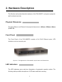
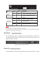
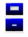
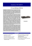
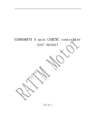
POH-0850TX
19” 8-port MidSpan POE HUB
USER MANUAL
Contents
1. Introduction ...........................................................................1
Features....................................................................................................................1
Package Contents.....................................................................................................2
2. Hardware Description ...........................................................3
Physical Dimension...................................................................................................3
Front Panel ...............................................................................................................3
LED Indicators...........................................................................................................3
Rear Panel ................................................................................................................4
Power On ..................................................................................................................4
Network Application ..................................................................................................5
3. Software Utility Installation ..................................................6
4. GUI Management ...................................................................9
Connecting to PoE ....................................................................................................9
System Setup & Control..........................................................................................10
System Information .................................................................................................11
Device Setting .........................................................................................................11
Port Specific Control ...............................................................................................13
Parametric Information............................................................................................15
5. Technical Specification ......................................................16
6. Appendix ..............................................................................18
Console Port Pin Assignments................................................................................18
i
1. Introduction
Power-over-Ethernet (PoE) eliminates the need to run 110/220 VAC power to other
devices on a wired LAN. Using Power-over-Ethernet system installers need to run only
a single CAT5 Ethernet cable that carries both power and data to each device. This
allows greater flexibility in the locating of network devices and significantly decreasing
installation costs in many cases.
There are two system components in PoE -- the Power Sourcing Equipment (PSE)
initiates the connection to the second component, the Powered Device (PD). The
current is transmitted over two of the four twisted pairs of wires in a Category-5 cable.
Power over Ethernet follows the IEEE 802.3af and is completely compatible with
existing Ethernet switches and networked devices. Because the Power Sourcing
Equipment (PSE) tests whether a networked device is PoE-capable, power is never
transmitted unless a Powered Device is at other end of the cable. It also continues to
monitor the channel. If the Powered Device does not draw a minimum current,
because it has been unplugged or physically turned off, the PSE shuts down the power
to that port. Optionally, the standard permits Powered Devices to signal to the PSEs
exactly how much power they need.
Features
POH-0850TX, 8-port power over Ethernet Hub
IEEE802.3af compliance, Power over Ethernet Mid-Spain mode
Remote power feeding up to 100 meters and for IEEE802.3 10Base-T, IEEE
802.3u 100Base-TX standard
Auto detect PD and classification power consumption level
Support manual control port detect and classification
Support system calibrate
Support Auto MDI/MDI-X depends on the uplink switch port.
1
Remote power feeding up to 100 meters and for IEEE802.3 10Base-T, IEEE
802.3u 100Base-TX standard
Centralized power distribution for PoE powered Device (PD)
High safety short circuit protection to prevent cable short
Supports IEEE 802.3af non-standard device, and support manual detect PD
Auto refresh port status and support Plug and Play feature for PD
Package Contents
Unpack the contents of the 8 port Power over Ethernet Hub and verify them
against the checklist below.
POS-0850TX, 8-port Power over Ethernet MidSpan Hub
Power Cord
RS-232 cable
User Guide
Software Utility CD-ROM
POH-0850TX
RS-232 Cable
User Guide
Power Cord
Software Utility CD-ROM
Figure 1-2. Package Contents
Compare the contents of your POH-0850TX package with the standard checklist
above. IF any item is missing or damaged, please contact your local dealer for service.
2
2. Hardware Description
This Section mainly describes the hardware of the POH-0850TX, and gives a physical
and functional overview.
Physical Dimension
The 8-port Power over Ethernet Hub physical dimension is: 440mm x 224mm x 44mm
(Lx W x H)
Front Panel
The Front Panel of the POH-0850TX consists of 8x RJ-45 Ethernet ports, LED
indicators, and one console port.
Figure 2-1. The appearance of POH-0850TX, 8 port Power over Ethernet Hub
LED Indicators
The LED Indicators gives real-time information of systematic operation status. The
following table provides descriptions of LED status and their meaning.
3
Figure 2-2. LED indicators
LED
Power
Forwarding
Status
Color
On
Green
Off
--
On
Power Off
Description
Power is transmitting to the device
Power is not transmitting to the
device
Orange
Off
Device is overload or short.
Device attached.
--
Blinking
Orange
Detecting the device
Table 2-1. The Description of LED Indicators
Notice
The “Power Off” LED is flashing when No PD attached.
And the LED goes off when PD attached. The corresponding “power forwarding” LED will then
go ON or OFF depending on switch action.
Rear Panel
The 3-pronged power plug, 2 Ventilation fan and on/off switching are located at the
rear panel of the 8 port Power over Ethernet Hub. The device will work with AC in the
range 100-240V AC, 50-60Hz.
Figure 2-3 Rear panel of the POH-0850TX
Power On
Connect the power cord to the power socket on the rear panel of the Switch. The other
4
side of power cord connects to the power outlet. The internal power supply of the
Switch works with voltage range of AC in the 100-240VAC, frequency 50~60Hz. Check
the power indicator on the front panel to see if power is properly supplied.
Network Application
The Power over Ethernet Hub can provides power to the PD that follow the IEEE
802.3af standard in the network. It can solve the problem of position limitation. The
network device can be installed in more appropriate position for better performance.
The following figure is an example of network application for Power over Ethernet Hub.
8x
9x
1x
2x
3x
10x
11x
12x
7x
8x
9x
4x
5x
6x
1x
2x
3x
10x
11x
12x
4x
5x
6x
AC power
C
7 8 9 101112
A
12 34 56
A
B
Switch
Ethernet
Ethernet
Core Switch
7x
7x
8x
9x
1x
2x
3x
10x
11x
12x
7x
8x
9x
4x
5x
6x
1x
2x
3x
10x
11x
12x
4x
5x
6x
AC power
C
7 8 9 101112
A
12 34 56
A
B
100M
Power over Ethernet Hub
AC power
PC or
Notebook
Power over Ethernet Hub provide
power to Powered device
POWERFAULT DATA ALARM
Powered Device, ex: SOHO
switch or Wireless AP
Figure 2-3 Power over Ethernet Hub network application
5
3. Software Utility Installation
Berfore you star to remote configuring PD, please intsall the software utility. Through
the software utility, you can easily to controll the PD that connect with PoE and view
the PD parameter informations. The software utility provides GUI interface and user
can easily to start with it. The software utility supports Windows environment -- Window
98, 2000, and XP. Please follow the below steps to install the software utility.
1. Insert the software utility CD-ROM into your CD-ROM drive.
2. Run the “setup.exe”.
3. You will see the installation screen display.
4. Then, click the “OK” button to go next step. See Figure 3-1.
Figure 3-1
5. Click the
button to start installation. See Figure 3-2.
6
Figure 3-2
6. When installation finishes, click “OK” button to finish. See Figure 3-3.
Figure 3-3
7. To run the software utility, go to “Star”
7
“Program”
“Power Over Ethernet”.
8. If you want to remove the software utility, go to “Star”
“Remove/ Add application”
“Power Over Ethernet”.
8
“Control Panel”
4. GUI Management
Connecting to PoE
Connecting the PoE with PC through the console port. Then, connect the PD (Powered
Device) to the port of PoE. Run the software utility and select the COM port form Serial
Link Setup function. You will see the main utility interface as figure 4-1.
Figure 4-1. The GUI management interface
The GUI management is divided into three parts:
System Setup & Control: main system level parameters setup for the POE
system.
System Information: display hardware version, firmware version, and utility
version.
Device Setting: you can save the device configuration to system, down load the
9
device current configuration to the utility system and enable auto refresh function.
Port Specific Control: each port specific function control and relate parameters
display.
Parametric Information: port parameters information display.
System Setup & Control
Master Enable: Enable/Disable the control of GUI. You must enable this item to do
the port controlling.
Calibrate System: when the system can’t do the port controlling, please remove the
PD device and enable this function to calibrate internal system.
PD Discovery R (ohms): set the PD resistor value range for the system detecting.
The default value range is 19000~26500. You can adjust the upper and lower limit
value when the system can’t detect the PD resistor in the default range. Please refer
to the “Discover R (ohms)” value in Parametric Information section to adjust the
upper and lower limit value. After you have adjusted the upper or lower limit value,
please unplug and then plug in the PD device.
Figure 4-2. System Setup & Control interface
10
System Information
Chip Version: display the system chipset version and revision information.
Firmware Version: display the system firmware version.
Utility Version: display the system utility version
Total Port Power (W): total of all the port power that the system provided to PD.
Figure 4-3. System Information interface
Device Setting
Enable Auto-Refresh: It allows the system auto refresh the system parameters.
The system auto refresh in every 2 seconds.
Load from Device
: To get the last configuration value from device to the
system utility.
Save to Device
: When you have configured the System Setup & Control and
Port Specific Control, please press
configuration into the system.
11
Save to Device
button to apply the new
Figure 4-4 Device Setting interface
12
Port Specific Control
Port Enable: enabling the port. This function is co-responding with “Master
Enable” function.
Bypass Detection: bypass the detection function.
Normally the system will try
to detect the 25kΩ resistor in an 802.3af compliant PD device. If the PD doesn’t
follow by IEEE 802.3af standard, you can enable this option to skip the detection
on PD. When you enable this function, the system will not perform the 25Ω
resistor detection for PD and directly transmit the power to PD. This function can
be cooperating with “PD discover R (ohms)” function in System setup & Control
section for non-standard compliant PD device.
[Note] after setting the Bypass Detection function, please unplug and then plug in
the PD device.
Bypass Classification: the system will skip the power classification and directly
transmit the power to PD when this function is enabling. Normally the system will
try to classify the 802.3af compliant PD device by checking the current class level.
The following table is a standard current classification level table.
[Note] after setting the Bypass Classification function, please unplug and then plug
in the PD device.
Class
Power Device
Classification Current
Power (W)
(mA)
Usage
MIN
MAX
MIN
MAX
0
Default
0.44
12.95
0
4
1
Optional
0.44
3.84
9
12
2
Optional
3.84
6.49
17
20
3
Optional
6.49
12.95
26
30
4
Optional
36
44
Reserved for future use
Table of Power Device Classification Levels
LED Status Indicators: current LED indicator display – green, yellow, and red.
13
The LED indicator will change depends on the PD status.
Green: It represents PD is connecting with the POE hub system and working
normally.
Yellow: It represents there is no PD connecting with the port.
RED: It represents PD’s power request is over the system support limit or the
cable is short.
Fault Status: display the PD error status message. There are three error status
and explain as following.
Null: It means there is no PD connected or the connected PD device status is
normal.
Overload: It means the current is over the PD current classification limited
(475mA @ 48V DC) that the situation happens over 50msec.
Mode Status: display the PD current operation mode status.
V sample or I sample: It means " Current sample or Voltage sample”.
When PD is detected and current is supplied, the POE hub will keep detecting
and sampling some current or voltage to ensure whether the PD still present
on this port. It is a IEEE 802.3af operating procedure.
R detect: When the port doesn’t connect with any PD, the POE hub will poll
each port and detects the resistor.
Figure 4-5. Port Specific Control interface
14
Parametric Information
Discovery R (ohms): display resistance value.
Port Current (mA): display current value.
Port Voltage (V): display voltage value.
Port Power (W): display watt value.
Class Current (mA): display class current value. When you enable the “Bypass
classification” function, the class current value will not show in here. Please refer
to the following table for output value.
Maximum power of levels at
Class
Usage
0
Default
15.4 Watts
1
Optional
4.0 Watts
2
Optional
7.0 Watts
3
Optional
15.4 Watts
4
Reserved for future use
Treat as Class 0
output of PSE
Determined Class: display power class. When you enable the “Bypass
classification” function, the class value will not show in here.
Figure 4-6. Parametric Information interface
15
5. Technical Specification
Standard
IEEE802.3af Power over Ethernet
Data in: 8 x RJ-45, Data pin 1,2,3,6
Connector
Data and power out: 8 x RJ-45. Data pin
1,2,3,6 Power pin (V+): 4,5, Power pin (V-): 7,8
Power out put
Management
Power over Ethernet mode
Per port DC 48V@350mA (Maximum), Per
system 125Watts (maximum)
Microsoft windows based application for power
management
Mid-Spain
Support Microsoft windows based application
Management utility
for power management
Plug and play for standard PD and without any
software configuration
System setup and control
System calibrate, IEEE 802.3af resistor range
adjust
Port Disable / Enable
Port configuration control
PD detect control (enable/disable)
Classification detect control (enable/disable)
Null: no PD present or PD status is normal
Fault status detect
Overload: current support over 475mA @ DC
48V and over 50 milliseconds
Mode status
System detects status –sample, V-sample and
R-detect
16
It will show current PD parameters which
Parametric information
include Discover-resistor detected value,
current, voltage, power consumption,
classification current and determined class
LED
Power
System: power
Per port: power Forwarding, power off
AC 100~240V, 50/60 Hz, 130 Watts, IEC
power socket with fuse and power switch
Power consumption
130 Watts (maximum)
Cooling
2 x DC fan
Weight
2.7Kg
Operating environment
0℃~ 40℃
Operating Temperature
-10℃ ~ 60℃
Humidity Temperature
10% ~ 90% (non-condensing)
Dimension
440mm x 224mm x 44mm (L x W x H)
EMI & safety
FCC Class A, CE, UL, cUL
17
6. Appendix
Console Port Pin Assignments
The female DB-9 serial port on the POE hub front panel is used to connect to the
switch for out-of-band console configuration. The web interface configuration program
can be accessed from PC running the system utility program. The pin assignments
used to connect to the serial port are provided in the following tables.
Figure 6-1. DB-9 Console Port Pin Numbers
DB-9 Port Pin Assignments
EIA Circuit
CCITT Signal
BB
104
Description
RxD (Received
Data)
Switch’s DB9 PC DB9
DTE Pin #
DTE Pin #
2
2
3
3
5
5
TxD
BA
103
(Transmitted
Data)
AB
102
SGND (Signal
Ground)
No other pins are used
18
Console Port to 9-Pin DTE Port on PC
Switch’s 9-Pin Serial
Port
CCITT Signal PC’s 9-Pin
DTE Port
2 RXD
<---------RXD ------------
3 TxD
3 TXD
-----------TXD ---------->
2 RxD
5 SGND
-----------SGND ----------
5 SGND
No other pins are used.
19