1
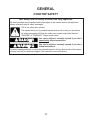
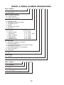
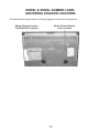
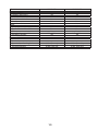
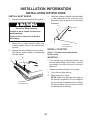
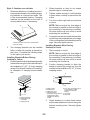
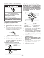
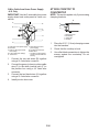
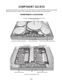
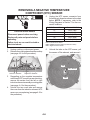
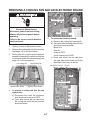
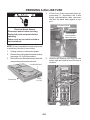
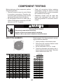
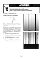
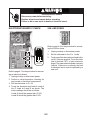
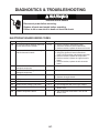
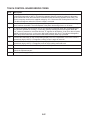
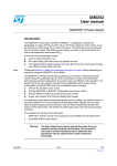
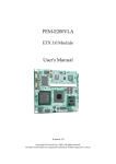
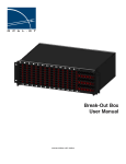
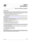
KAC-47
TECHNICAL EDUCATION
TOUCH-ACTIVATED
ELECTRONIC
INDUCTION COOKTOP
MODELS: KICU508SBL & KICU568SBL
JOB AID 4317409
FORWARD
This KitchenAid Job Aid “Touch-Activated Electronic Induction Cooktop” (Part No. 4317409), provides the In-Home Service Professional with information on the installation, operation, and service
of the Touch-Activated Electronic Induction Cooktop. For specific information on the model being
serviced, refer to the “Use and Care Guide,” or “Wiring Diagram” provided with the cooktop.
The Wiring Diagrams used in this Job Aid are typical and should be used for training purposes
only. Always use the Wiring Diagram supplied with the product when servicing the cooktop.
GOALS AND OBJECTIVES
The goal of this Job Aid is to provide information that will enable the In-Home Service Professional
to properly diagnose malfunctions and repair the Touch-Activated Electronic Induction Cooktop.
The objectives of this Job Aid are to:
• Understand and follow proper safety precautions.
• Successfully troubleshoot and diagnose malfunctions.
• Successfully perform necessary repairs.
• Successfully return the cooktop to its proper operational status.
WHIRLPOOL CORPORATION assumes no responsibility for any repairs made on
our products by anyone other than authorized In-Home Service Professionals.
Copyright © 2007, Whirlpool Corporation, Benton Harbor, MI 49022
- ii -
TABLE OF CONTENTS
Page
GENERAL .............................................................................................................................. 1-1
Cooktop Safety .................................................................................................................. 1-1
Model & Serial Number Designations ................................................................................ 1-2
Model & Serial Number Label And Wiring Diagram Locations ........................................... 1-3
Specifications ..................................................................................................................... 1-4
INSTALLATION INFORMATION ............................................................................................ 2-1
Installation Instructions ...................................................................................................... 2-1
PRODUCT OPERATION ....................................................................................................... 3-1
Theory Of Operation .......................................................................................................... 3-1
Troubleshooting ................................................................................................................. 3-4
COMPONENT ACCESS ........................................................................................................ 4-1
Component Locations ........................................................................................................ 4-1
Removing The Cooktop Glass ........................................................................................... 4-2
Removing The Touch Control Board .................................................................................. 4-3
Removing An Induction Element Assembly ....................................................................... 4-4
Removing A Negative Temperature Coefficient (NTC) Sensor .......................................... 4-6
Removing A Cooling Fan And An Electronic Board ............................................................ 4-7
Removing A 20A Line Fuse ................................................................................................ 4-8
COMPONENT TESTING ........................................................................................................ 5-1
Induction Elements ............................................................................................................ 5-1
Negative Temperature Coefficient (NTC) Sensor............................................................... 5-2
Electronic Board IC Check ................................................................................................. 5-3
20A Line Fuses .................................................................................................................. 5-3
DIAGNOSTICS & TROUBLESHOOTING ............................................................................. 6-1
Electronic Board Error Codes ............................................................................................ 6-1
Touch Control Board Error Codes ...................................................................................... 6-2
WIRING DIAGRAMS ............................................................................................................. 7-1
30˝ Cooktop ...................................................................................................................... 7-1
36˝ Cooktop ...................................................................................................................... 7-2
- iii -
— NOTES —
- iv -
GENERAL
COOKTOP SAFETY
Your safety and the safety of others are very important.
We have provided many important safety messages in this manual and on the appliance.
Always read and obey all safety messages.
This is the safety alert symbol.
This symbol alerts you to potential hazards that can kill or hurt you and others.
All safety messages will follow the safety alert symbol and either the word
“DANGER” or “WARNING.” These words mean:
DANGER
You can be killed or seriously injured if you don’t
immediately follow instructions.
WARNING
You can be killed or seriously injured if you don’t
follow instructions.
All safety messages will tell you what the potential hazard is, tell you how to reduce the chance
of injury, and tell you what can happen if the instructions are not followed.
1-1
MODEL & SERIAL NUMBER DESIGNATIONS
MODEL NUMBER
K
IC
U
50
PRODUCT GROUP
K = KITCHENAID
PRODUCT IDENTIFICATION
EC = ELECTRIC COOKTOP
GC = GAS COOKTOP
IC = INDUCTION COOKTOP
MERCHANDISING SCHEME
C = CERAMIC GLASS
S = STANDARD / PORCELAIN METAL
T = TEMPERED GLASS
U = ULTIMA
V = VBL PRO LINE SERIES
X = 208 VOLTS
CAPACITY / SIZE / SERIES / CONFIGURATION
1ST POSITION
2ND POSITION
0 = 2 BURN. / ELEM.
0 = 30˝ WIDE
1 = STANDARD
2 = 42˝ OR 12˝ WIDE
2 = GRILL / GRIDDLE
3 = 33˝ WIDE
3 = TEMP. GLASS
5 = 15˝ WIDE
4 = COMMERCIAL
6 = 36˝ WIDE
5 = CERAMIC GLASS
8 = 48˝ WIDE
FEATURE CODE
0 = STANDARD ELEMENTS / BURNERS
1 = RADIANT ELEMENTS
2 = DUAL ELEMENTS OR SEALED BURNERS W/GRILL
6 = 5 BURNERS / ELEMENTS
7 = HALOGEN ELEMENTS / OR 6 BURNERS
8 = TOUCH CONTROLS
9 = INDUCTION
YEAR OF INTRODUCTION
S = 2006
COLOR CODE
BL = BLACK
ENGINEERING CHANGE (0, 1, 2, ETC.)
SERIAL NUMBER
XT
DIVISION RESPONSIBILITY
XT = OXFORD
YEAR OF PRODUCTION
U = 2007
WEEK OF PRODUCTION
24 = 24TH WEEK
PRODUCT SEQUENCE NUMBER
U 24
01234
1-2
8
S
BL
0
MODEL & SERIAL NUMBER LABEL
AND WIRING DIAGRAM LOCATIONS
The Model/Serial Number label and Wiring Diagram locations are shown below.
Wiring Diagram Location
(On Bottom Of Cooktop)
Model & Serial Number
Label Location
1-3
SPECIFICATIONS
Model Number
Model Description
KICU508SBL
KICU568SBL
Touch Activated 36˝ Ceramic
Touch Activated 30˝ Ceramic
Premium Black Induction Cooktop Premium Black Induction Cooktop
30˝
36˝
Size-Configuration
Dimensions/Specifications
Exterior Dimensions
Overall Height (in)
3-1/4˝
3-1/4˝
Overall Width (in)
31˝
37˝
Overall Depth (in)
21-9/16˝
21-9/16˝
Cutout Dimensions
Burner Box Height
3˝
3˝
Cutout Width (in)
29-1/2˝
35-1/2˝
Cutout Depth (in)
20-1/2˝
20-1/2˝
Weight
Net Weight (lbs)
44.1
50.7
Ratings
Electric Voltage/Phase/Frequency (Hz) 240/208 Volt,Single Phase,60Hz 240/208 Volt,Single Phase,60Hz
Total Connected Load In kW
240 Volts (Preferred)
7.2
10.6
208 Volts
6.65
10.3
Circuit Amps
30 Amp (240V) / 32 Amp (208V)
45 Amp (240V) / 48 Amp (208V)
Exterior
Cooktop Finish
Ceramic Glass
Ceramic Glass
Cooktop Color
Premium Black
Premium Black
Cooktop Controls
Touch Activated
Touch Activated
Cooktop Control Type
LED
LED
Cooktop Control #
4
5
Electronic Control
Yes - Touch Activated LED Control Yes - Touch Activated LED Control
Keep Warm
Yes (“h”)
Yes (“h”)
Keep Warm Switch
Yes (Press + and - at the same time) Yes (Press + and - at the same time)
Cooktop Features
Power On Light
4
5
Autofocus Light
No
Yes
Hot Surface Indicator
4 (“H”)
5 (“H”)
Kitchen Timer
Yes (99 Min.)
Yes (99 Min.)
Control Lock
Yes
Yes
Ele R Front Size & Type
5-7/8˝ Single Induction
8-1/4˝ Single Induction
Ele RF Output (W@240/208V)
1400W/1320W
2200W/2075W
Ele L Front Size & Type
7-1/8˝ Single Induction
7-1/8˝ Single Induction
Ele LF Output (W@240/208V)
1800W/1700W
1800W/1700W
Ele R Rear Size & Type
5-7/8˝ Single Induction
11˝ Single Induction
Ele RR Output (W@240/208V)
2400W/2200W
1400W/1320W
Ele L Rear Size & Type
7-1/8˝ Single Induction
7-1/8˝ Single Induction
Ele LR Output (W@240/208V)
1800W/1700W
1800W/1700W
Ele C Front Size & Type
11˝/ 7-1/8˝ Dual Zone Induction
Ele CF Output (W@240/208V)
3600W - 1800W/3120 - 1700W
1-4
Model Number
Miscellaneous
Product Literature
Installation Instructions
Parts List
Service Manual/Job Aid
Tech Sheet
Use & Care Guide
Other
Agency Approvals
Approved to Install Over BI Oven
Hardware
Power Cord Length & # Wires
Residential Use Only
Warranty
Limited
Extended
Ceramic Glass Cooking Surface
Electronic Controls
Electrical Elements
KICU508SBL
KICU568SBL
Yes
Yes
Yes
Yes
Yes
Yes
Yes
Yes
Yes
Yes
UL, CUL
Yes
Yes
3 Foot/3 Wire
Yes
UL, CUL
Yes
Yes
3 Foot/3 Wire
Yes
12 Mo
12 Mo
60 Mo. Parts only
60 Mo. Parts only
60 Mo. Parts only
60 Mo. Parts Only
60 Mo. Parts Only
60 Mo. Parts Only
1-5
— NOTES —
1-6
INSTALLATION INFORMATION
INSTALLATION INSTRUCTIONS
INSTALL HEAT SHIELD
1.
4.
Decide on the final location for the cooktop.
WARNING
B
Excessive Weight Hazard
Use two or more people to move and
install cooktop.
Failure to do so can result in back or
other injury.
2.
3.
A
Using two screws, reattach the heat shield
to the underside of the cooktop at the
predrilled holes as shown in the following
illustration.
A
Using two or more people, place the
cooktop upside down on a covered work
surface.
Remove the heat shield from the cooktop.
Set the two screws aside for reattaching
the heat shield.
A. Heat shield
B. Predrilled holes
INSTALL COOKTOP
Style 1: Cooktop over undercounter
built-in oven
IMPORTANT:
• Your cooktop may not be approved for use
over an undercounter built-in oven. Contact
your dealer to confirm that your cooktop is
approved.
• Clamping brackets should not be used.
B
1.
2.
A. Heat shield
B. Remove screws
2-1
Turn cooktop right side up.
Place cooktop in cutout.
NOTE: Make sure that the front edge of
the cooktop is parallel to the front edge of
the countertop. If repositioning is needed,
lift entire cooktop up from cutout to avoid
scratching the countertop.
2.
Style 2: Cooktop over cabinets
1. Determine whether your cabinet construction provides clearance for installing clamping brackets at cooktop base ends. This
is the recommended location. Clamping
brackets can be installed on the back of
cooktop base bottom, if necessary.
3.
4.
A
5.
B
A. Attachment screw holes, side or back locations
B. Front of cooktop
Rotate brackets so they do not extend
beyond edge of cooktop base.
Tighten screws enough to hold brackets
in place when cooktop is placed into the
cutout.
Turn the cooktop right side up and place
in cutout.
NOTE: Make sure that the front edge of
the cooktop is parallel to the front edge of
the countertop. If repositioning is needed,
lift entire cooktop up from cutout to avoid
scratching the countertop.
Loosen the screws and rotate the brackets
so that they are perpendicular to the edge
of the cooktop base and extend beyond its
edge. Securely tighten screws.
Installing Brackets After Placing
Cooktop in Cutout
1. Place cooktop in cutout.
NOTE: Make sure that the front edge of
the cooktop is parallel to the front edge of
the countertop. If repositioning is needed,
lift entire cooktop up from cutout to avoid
scratching the countertop.
2. Position clamping bracket to allow the
bracket to extend far enough out from the
cooktop for the installation of 2-1/2˝ (6.4 cm)
clamping screws
2.
The clamping brackets can be installed
before or after the cooktop is placed into
the cutout. Complete the following steps
for the option you choose.
Installing Brackets Before Placing
Cooktop in Cutout
1. Position bracket to allow the clamping bracket
to extend far enough out from the cooktop for
the installation of 2-1/2˝ (6.4 cm) clamping
screws. See “Attach Cooktop to Countertop”
for illustration of clamping screw installation.
A
G
F
E
D
B
C
A
A. Glass cooktop
B. Cooktop base
C. Attachment screw
D. Clamping bracket
(extends far enough beyond
cooktop base to allow
installation of clamping
screws)
B
C
A. Clamping bracket
B. Attachment screw
and washer
C. Clamping screw
3.
2-2
E. 2-1/2" (6.4 cm) clamping screw
(to be installed in “Attach
Cooktop to Countertop”
section)
F. Countertop
G. Foam seal
Attach brackets to cooktop base bottom
with bracket attachment screws using the
bracket mounting holes. Securely tighten
screws.
MAKE ELECTRICAL CONNECTION
4-Wire Cable from Home Power Supply
IMPORTANT: Use the 4-wire cable from home
power supply in the U.S. where local codes do
not allow grounding through neutral, New Branch
circuit installations (1996 NEC), mobile homes
and recreational vehicles, new construction,
and in Canada.
WARNING
A
Electrical Shock Hazard
Disconnect power before servicing.
Use 8 gauge copper wire.
Electrically ground cooktop.
Failure to follow these instructions can
result in death, fire, or electrical shock.
B
G
C
D
This cooktop is manufactured with a frame-connected, green (or bare) ground wire.
1. Disconnect power.
2. Remove junction box cover if it is present.
3. Connect the flexible cable conduit from the
cooktop to the junction box using a UL listed
or CSA approved conduit connector.
1.
A
3.
A. UL listed or CSA approved conduit connector
5.
Tighten screws on conduit connector if
present.
See “Electrical Connection Options Chart”
to complete installation for your type of
electrical connection.
4.
Electrical Connection Options Chart
If your home has:
Go to Section:
4-wire
4-Wire Cable from Home
Power Supply
5.
½"
(1.3 cm)
3-wire
H
I
F. White wire (from home
A. Cable from home power
power supply)
supply
G. UL listed wire connector
B. Red wires
C. Green (or bare) ground wire H. Black wires
(from cooktop)
I. UL listed or CSA approved
conduit connector with
D. 3-Wire cable from cooktop
wire bushing
E. Junction box
2.
4.
E
F
3-Wire Cable from Home
Power Supply
½"
(1.3 cm)
2-3
Connect the two red wires (B) together
using a UL listed wire connector.
Connect the green (or bare) ground wire
(C) from the cooktop cable to the green
(or bare) ground wire (in the junction box)
using a UL listed wire connector.
Put a UL listed wire connector on the end
of the white wire (F).
NOTE: Do not connect the green (or bare)
ground wire to the neutral (white) wire in
the junction box.
Connect the two black wires (H) together
using a UL listed wire connector.
Install junction box cover.
ATTACH COOKTOP TO
COUNTERTOP
3-Wire Cable from Home Power Supply
- U.S. Only
IMPORTANT: Use the 3-wire cable from power
supply where local codes permit a 3-wire connection.
A
NOTE: This section applies only if you are using
clamping brackets.
D
E
C
B
A
B
F
G
A. Clamping screw
B. Countertop
C. Foam seal
D. Cooktop
H
C
I
D
A. Cable from home power supply
B. Red wires
C. Green (or bare) ground wire
from cooktop
D. 3-wire cable (from cooktop)
E. Junction box
1.
2.
3.
4.
1.
F. White wire (from home
power supply)
G. UL listed wire connector
H. Black wires
I. UL listed or CSA approved
conduit connector with wire
bushing
2.
3.
Connect the two red wires (B) together
using a UL listed wire connector.
Connect the green (or bare) cooktop cable
wire (C) to the white (neutral) wire (F) in
the junction box using a UL listed wire
connector.
Connect the two black wires (H) together
using a UL listed wire connector.
Install junction box cover.
2-4
Place the 2-1/2˝ (6.4 cm) clamping screws
into the brackets.
Check that the cooktop is level.
Use a flat-blade screwdriver to tighten the
screws against the countertop. Do not
overtighten.
PRODUCT OPERATION
THEORY OF OPERATION
Principles Of Induction Heating
A temperature sensor under the glass is used
in order to protect the inductor, and it moreover
allows detecting that an empty container is
being over-heated and stopping the heating
process.
The use of induction heating in glass-ceramic
cooking devices has existed since 1987.
With this technique, the container is heated
directly. Therefore the cooking surface heats
up only as a result of the heat transmitted from
the container to the glass, which is much lower
than in conventional systems.
The base of the container is heated by the electric currents that circulate in its base and which
are induced by a variable, medium-frequency
magnetic field generated by the inductors located underneath the ceramic glass.
Only containers with a base made of ferromagnetic steel or iron can be used with induction
cooktops. Containers that cannot be used for induction can be recognized by a magnet test.
Even though it is recommendable to use containers that fit the size of the cooking zone,
containers of a smaller diameter can be used
without causing notable reductions of efficiency.
The cooktop control reduces the power delivered to small containers and, if applicable, stops
supplying power when the container does not
have the minimum required diameter.
Advantages Of Induction Heating
Faster Cycle Time
• Heat is developed directly and instantly within
1 second inside the pot or pan, allowing a
much quicker startup than other heating
equipment. Heating process times can be
dramatically reduced & production output
can be significantly increased.
• With induction cooking the heat level is every
bit as instantaneous, and as exact, as with gas,
yet with none of the many drawbacks of gas
(carbon monoxide, loss of flame etc.). Induction elements can be adjusted to increments
as fine as the cooking utensil cares to supply,
just like gas, and—again very important to
serious cooks—such elements can run at as
low a cooking-heat level as wanted for gentle
simmering and suchlike (something even gas
is not always good at).
The power inverter transforms the 50 Hz of
the power grid into an alternating current with
a frequency between 20 and 60 Hz.
Direct heating of the container base provides
the induction system with very fast heating.
Likewise, the system reacts very quickly to
power level changes.
Induction provides very precise control of the
power levels, wherefore it allows delicate recipes
to be prepared.
High Thermal Efficiency And
Increased Profitability
• This energy-efficient process converts up to
90% of the energy expended into useful heat
to reduce utility costs. (With gas ranges up to
60% of the heat is normally wasted through
indirect gas combustion.) Stand-by losses
are reduced to a minimum.
• The costs of exhaust duct installation and air
conditioning running costs are saved.
3-1
User-Friendly
• As mentioned earlier, induction cooking energy is supplied directly to the cooking utensil
by the magnetic field; thus, almost all of the
source energy gets transferred to that cooking utensil. With gas or conventional electric
elements (including halogen), the energy is
first converted to heat and only then directed
to the pot or pan with a lot of that heat going to waste heating up your kitchen instead
of heating up your food. (As a comparison,
40%—less than half—of the energy in gas
gets used to cook, whereas with induction
84% percent of the energy in the electricity
used gets used to cook (and the rest is not
waste heat as it is with gas). There are two
important heat-related consequences of that
fact:
• Working conditions are improved with the
absence of smoke and heat produced by
heating equipment. You can touch the outer
casing without getting burned.
• If the electricity supply to your home is interrupted, you will be unable to cook; gas supplies can be interrupted, too, but such interruptions are normally somewhat less likely
than electricity interruptions. If the electricity
where you are frequently goes out for hours
at a time, the loss of cooking ability may be
an issue for you.
Pinpoint Accuracy
• Power input is precisely controlled to achieve
the exact temperature required for heating.
Heat is developed directly inside the pot or
kettle or cooktop.
• With gas, when you adjust the element setting, the energy flow adjusts instantly.
• But with induction cooking the heat level is
every bit as instantaneous, and as exact, as
with gas, yet with none of the many drawbacks
of gas. Induction elements can be adjusted to
increments as fine as the cooker maker cares
to supply, just like gas, and—again very important to serious cooks—such elements can
run at as low a cooking-heat level as wanted
for gentle simmering and suchlike (something
even gas is not always good at).
• Moreover, gas—induction’s only real competition—has special risks of its own, not all
of which are as well known as they perhaps
should be. While the risk of a gas flame, even
a pilot light, blowing out and allowing gas to
escape into the house is relatively small, it
does exist.
Cooler kitchens:
• Of course the cooking vessel and the food
itself will radiate some of their heat into the
cooking area—but compared to gas or other
forms of electrically powered cooking, induction makes for a much cooler kitchen.
Cool stove top:
• The stove top itself barely gets warm except
directly under the pan (and that only from such
heat as the pan bottom transfers). No more
burned fingers, no more baked-on spills, no
more danger with children around.
Environmentally Sound
• Induction heating is a clean, non-polluting
process. It produces much less smoke or
waste heat to alter the surrounding environment.
• It is an obvious but still very important fact that
induction cooktops are powered by electricity.
Not every home actually has a gas pipeline
available to it—for many, the only “gas” option
is propane, with the huge propane tank and
regular truck visits. But everyone has clean,
silent, ever-present electricity.
• Burning gas has byproducts that are vaporized, but eventually condense on a surface
somewhere in the vicinity of the cooktop.
Electrical cooking of any kind eliminates such
byproducts.
Maximum Repeatability
• With modern induction heating equipment,
the heating pattern is always the same for a
given set-up, cycle after cycle and day after
day.
3-2
Noises that are Common to the
Normal Operation of Induction
Cooktops
different speeds according to the temperature
detected. The fan can also continue operating
when the cooktop is turned off after being
used if the detected temperature continues
to be high.
NOTE: All these noises are normal and inherent to induction technology, and they are not a
sign of any breakdown.
The noises that occur with greatest frequency
are those with containers that have a “sandwich”
type base.
Induction heating technology is based on the
capacity that certain metal materials have to
vibrate when they are subject to high frequency
waves.
Under certain circumstances, these vibrations
may make certain sounds of a low volume due
to the following:
• Low tone noise, similar to that of a transformer: It occurs when cooking at high power
levels. It is due to the enormous amount of
energy that the cooktop is supplying to the
container. It disappears or attenuates as the
power level used is reduced.
• Soft whistling: They occur when the container is empty. They disappear or attenuate when water or the food to be cooked is
added.
• Crackling: This kind of noise may occur in
containers composed of layers of different
materials. The noise is due to the vibration
in the separation zones between the various
layers of material. This noise is proper to the
container. It can change according to the
quantity and type of food that is cooked.
• Sharp whistling (beeps): They occur basically with containers composed of different
layers of materials when two adjacent cooking zones are started up at the same time
and at maximum power. They disappear or
attenuate when the power is reduced.
• Intermittent clicks: They are noises caused
by the commutations of the control electronics, above all when low power levels are
selected.
• Fan noise: In order to control the correct
operation of the electronics, they must work at
a controlled temperature. To achieve this, the
cooktop is equipped with a fan that works at
Overview of Induction Cookware
• All pots and pans with a ferromagnetic base
are valid for induction.
• Only containers that have a base where a
magnet remains adhered can be used.
• The induction system does not heat up other
kinds of containers, and the power level indicator on the display will blink.
• The minimum diameter of the container must
likewise be taken into account.
Pots and Pans good for Induction
Cooking
• Enamelled steel pots and pans.
• Cast iron pots and pans.
• Special stainless steel utensils for induction
cooking.
Pots and Pans not good for Induction Cooking
•
•
•
•
•
•
•
3-3
Non-ferromagnetic or non-metallic materials.
Aluminum pots and pans.
Copper pots and pans.
Brass pots and pans.
Standard stainless pots and pans.
Glass (“Pyrex”) containers.
Earthenware pans.
TROUBLESHOOTING
Display shows messages
Nothing will operate
• Is “E” flashing on the surface cooking
area display? Thoroughly wipe or remove
any object on touch keys. When finished
cleaning, touch the correct key. The flashing
should stop.
• Is “E” flashing on all the surface cooking
area displays with a signal beeping? The
main switch has been kept on for more than
5 seconds. Wipe up any soil on the touch
keys. Remove any objects on the touch keys.
Reset the cooktop.
• Is the display flashing when you place a
saucepan on an induction surface cooking
area? Check that the saucepan is magnetic.
Check that the diameter of the saucepan is
large enough. Center the saucepan on the
surface cooking area. Allow the saucepan to
cool down in the event that it has become hot
when used. Switch the surface cooking area
off, then on again. If the display still does not
light up, turn power off at the circuit breaker.
Wait 20 seconds and turn power back on.
• Is the Performance boost function display
flashing and switching off? The Performance boost function operates the surface
cooking area with the most power. During
long cooking times, it is possible that the
function will switch the surface cooking area
off to protect the cooktop from overheating.
You can continue to use the cooktop if the
display is not flashing.
• Is the cooktop wired properly? See the Installation Instructions for more information.
• Has a household fuse blown, or has a
circuit breaker tripped? Replace the fuse
or reset the circuit breaker. If the problem
continues, call an electrician.
Cooktop will not operate
• Is the cooktop control set correctly? Touch
SELECT before selecting a setting.
• Is the “Control Lock” Cooktop Lockout
set? See “Control Lock” in the Use & Care
Guide.
• Has the cooktop turned off by itself? The
power off key was unintentionally touched.
Press power key again. Reset the cooktop.
Excessive heat around cookware on cooktop
• Is the cookware the proper size? Use
cookware about the same size as the surface
cooking area. Cookware should not extend
more than 1/2˝ (1.3 cm) outside the cooking
area.
Cooktop cooking results not what expected
• Is the proper cookware being used? See
“Cookware” in the Use & Care Guide.
• Is the cooktop control set to the proper
heat level? See “Cooktop Controls” in the
Use & Care Guide.
• Is the appliance level? Level the appliance.
See the Installation Instructions.
3-4
• Is the display flashing “Er” and numbers?
If an “Er” and a series of numbers appear in
the display panel, turn power off at the circuit
breaker. Turn on again. If a problem continues, call customer service. See “Assistance
or Service” in the Use & Care Guide.
• Is the display flashing “F” and numbers?
If “F” and a number are alternately flashing
on the display, refer to the following table for
possible solutions.
Error
Code
Error
Operational cooktop sounds
• Is there a low humming? This occurs when
cooking at high power. The cause of this is
the amount of energy which is transmitted
from the appliance to the cookware. This
sound will quiet or go away when the power
is turned down.
• Is there a crackling? This sound occurs
when cookware is used which consists of
different materials. The noise is caused by
vibrations in the joint faces between the different layers. It may change depending on the
amount and type of food being cooked.
• Is there a fan noise? The electronics require a controlled temperature in order to
function reliably. The cooktop is fitted with a
fan which runs at various speeds according
to the temperature detected. The fan may
also continue to run even after the cooktop
has been switched off, if the temperature it
detects is too high.
Solution
F0
An internal error
was detected.
Disconnect power. Wait
5 seconds before reconnecting
power. If the symbol appears
again, call customer service.
F2
The surface
cooking area is
too hot and has
turned off.
Remove the pans from the
surface cooking area. “F2” will
disappear when the surface
cooking area has cooled down. If
you turn the surface cooking area
back on and “F2” reappears, the
cooktop is still too hot. Turn off
the surface cooking area and
allow it to cool.
F4
The pot or pan is
too close to the
control panel.
Make sure the pot or pan is
centered on the surface cooking
area and nothing hot is on the
touch control panel. Wait
5 minutes for control panel to
cool. If “F4” appears after turning
the surface cooking area back on,
call customer service.
F8
The surface
The surface cooking area
cooking area has automatic shutoff was activated.
been in operation Turn off the surface cooking area.
for too long.
c1
The power
voltage is too
low.
c2/c3
The surface
The surface cooking area
cooking area has automatic shutoff was activated.
overheated.
Wait 5 minutes, for it to cool
down, then turn it back on.
Turn off the cooktop. Wait
5 seconds, then turn it back on. If
this continues, contact a qualified
electrician.
3-5
— NOTES —
3-6
COMPONENT ACCESS
This section instructs you on how to service each component inside the KitchenAid Touch-Activated
Electronic Induction Cooktop. The components and their locations are shown below.
COMPONENT LOCATIONS
Negative Temperature Coefficient (NTC) Sensor
(1 For Each Element)
Left Induction Element Assembly
Touch Control Board
Left Cooling Fan
Right Induction Element Assembly
Right Cooling Fan
Left Electronic Board
Right Electronic Board
2 20A Fuses (Inside Burner Box)
4-1
REMOVING THE COOKTOP GLASS
3.
WARNING
4.
Remove the fourteen flat-head screws
from the front, rear, and side ceramic glass
brackets.
Remove the two small side brackets from
the cooktop base.
Fron
t/Re
ar B
rack
Cooktop Glass
et Sc
rews
Electrical Shock Hazard
Disconnect power before servicing.
Replace all parts and panels before
operating.
Failure to do so can result in death or
electrical shock.
Side Bracket Screws
1.
2.
Unplug cooktop or disconnect power.
Remove the cooktop from its mounting
location, (see “Installation Instructions” in
Section 2). Position the cooktop so that
you can access the bracket screws below
the cooktop glass.
Small Side Bracket
Cooktop Base
5.
Lift and remove the ceramic glass from the
cooktop base.
Cooktop Glass
4-2
REMOVING THE TOUCH CONTROL BOARD
3.
WARNING
Press and unlock the two holder tabs, raise
the touch control board, and remove the
board from the holder.
Touch Control Board Holder Tabs
Electrical Shock Hazard
Disconnect power before servicing.
Replace all parts and panels before
operating.
Failure to do so can result in death or
electrical shock.
1.
2.
4.
Slide the three edge connectors off the
touch control board.
Touch Control Board Connectors
Unplug cooktop or disconnect power.
Remove the cooktop glass from the cooktop
(see page 4-2 for the procedure).
5.
To remove the touch control board holder,
remove the four mounting screws.
Touch Control Board Holder & Screws
Touch Control Board
4-3
REMOVING AN INDUCTION ELEMENT ASSEMBLY
WARNING
Electrical Shock Hazard
Disconnect power before servicing.
Replace all parts and panels before
operating.
Failure to do so can result in death or
electrical shock.
1.
2.
Left Induction Element
Mounting Plate Screws (3)
Unplug cooktop or disconnect power.
Remove the cooktop glass from the cooktop
(see page 4-2 for the procedure).
Right Induction Element
Mounting Plate Screws (4)
Left Induction Elements
3.
Right Induction Elements
Remove the screws from the left or right
induction element assembly mounting plate
(see the right photos).
4-4
4.
Disconnect the induction element assembly
connectors from the electronic board as
follows:
2-wire connector at CNT3.
2-wire connector at CNT1.
Red wire at FST1.
Green wire at FST2.
Induction element screw terminals at CNX1,
CNX2, CNX3 & CNX4.
FST2
5.
6.
LR Element
Cover & Tabs
FST1
CNT1
Left Induction Element
Assembly Shown
Remove the induction element assembly
from the cooktop.
Unhook the two cover tabs and remove
the cover from the induction element you
are replacing.
LF Element
Cover & Tabs
CNX2
CNX1
Left Induction Element Assembly
CNX3
CNX4
CNT3
Electronic Board
RR Element
Cover & Tabs
RF Element
Cover & Tabs
Right Induction Element Assembly
4-5
REMOVING A NEGATIVE TEMPERATURE
COEFFICIENT (NTC) SENSOR
WARNING
5.
Electrical Shock Hazard
Disconnect power before servicing.
Replace all parts and panels before
operating.
Failure to do so can result in death or
electrical shock.
1.
2.
Unplug the NTC sensor connector from
the electronic board as shown in the chart
below. NOTE: If necessary, refer to the
Wiring Diagrams in Section 7 for the connector locations.
ELEMENT LOCATION
NTC CONNECTOR
LF
CNT3 (LEB)
LR
CNT1 (LEB)
C
CNT1 (MEB)
RF
CNT3 (REB)
RR
CNT1 (REB)
LEB = Left Electronic Board
MEB = Middle Electronic Board (5 element models)
REB = Right Electronic Board
Unplug cooktop or disconnect power.
Remove the cooktop glass from the cooktop
(see page 4-2 for the procedure).
6.
Unhook the tabs on the NTC sensor, pull
the sensor off the element, and remove it.
Tabs
NTC Sensor
Left NTC Sensors
3.
4.
Right NTC Sensors
Depending on the negative temperature
coefficient (NTC) sensor you are servicing,
remove the screws from the left or right
induction element assembly mounting plate
(see page 4-4 for the procedure).
Unhook the two cover tabs and remove
the cover from the induction element NTC
sensor you are replacing (see page 4-5 for
the procedure).
Tabs
4-6
REMOVING A COOLING FAN AND AN ELECTRONIC BOARD
WARNING
Electronic Board
Cooling Fan
Electrical Shock Hazard
Disconnect power before servicing.
Replace all parts and panels before
operating.
Failure to do so can result in death or
electrical shock.
1.
2.
3.
CNT5
5.
Unplug cooktop or disconnect power.
Remove the cooktop glass from the cooktop
(see page 4-2 for the procedure).
Remove the left or right induction element
assembly, depending on which cooling fan
or electronic board you are removing (see
page 4-4 for the procedure).
Left Cooling Fan
Tabs
Right Cooling Fan
To remove an electronic board:
a) Remove the cooling fan (see step 4).
b) Disconnect the following wires from the
electronic board terminals:
Black at N.
Red at L.
Green at FST3
4-wire connector at CNT4.
c) Press and unlock the two tabs from
the right side of the board and lift the
electronic board from its holder.
GN (FST3) RD (L)
BK (N)
Tab
Electronic Board
Left Electronic Board
4.
Right Electronic Board
To remove a cooling fan (see the top
right photo):
a) Disconnect the 2-wire fan connector
from electronic board pins CNT5.
b) Press and unlock the two tabs from
the cooling fan and lift the fan from the
electronic board.
CNT4
4-7
Tab
REMOVING A 20A LINE FUSE
4.
WARNING
LIft the front of the component panel approximately 8˝, disconnect the 4-wire
bridge communication cable connector,
and rest the panel back against a support.
Component Panel
Electrical Shock Hazard
Disconnect power before servicing.
Replace all parts and panels before
operating.
Failure to do so can result in death or
electrical shock.
4-Wire Bridge
Communication
Cable Connector
NOTE: A fuse is installed for each relay board
to avoid short circuits in the cooktop.
1. Unplug cooktop or disconnect power.
2. Remove the cooktop glass from the cooktop
(see page 4-2 for the procedure).
3. Remove the ten flat-head screws from the
component panel and burner box.
5.
Remove the defective fuse from its fuse
holder clips and install a new 20A fuse in
its place.
Component Panel
Burner Box
Screw
(1 of 10)
20A Line Fuses
4-8
COMPONENT TESTING
• Check all connections before replacing
components, looking for broken or loose
wires, failed terminals, or wires not pressed
into connectors far enough.
• Resistance checks must be made with
power cord unplugged from outlet, and
with wiring harness or connectors disconnected.
Before testing any of the components, perform
the following checks:
• The most common cause for control failure
is corrosion on connectors. Therefore, disconnecting and reconnecting wires will be
necessary throughout test procedures.
• All tests/checks should be made with a
VOM or DVM having a sensitivity of 20,000
ohms-per-volt DC, or greater.
WARNING
Electrical Shock Hazard
Disconnect power before servicing.
Replace all parts and panels before operating.
Failure to do so can result in death or electrical shock.
Refer to page 4-4 for the procedure for accessing the induction elements.
1. Unplug cooktop or disconnect power.
2. Disconnect the induction element wires
from the electronic board.
3. Set the ohmmeter to the R x 1 scale.
4. Touch the ohmmeter test leads to the induction element wire terminals. The meter
should indicate less than 1 Ω.
INDUCTION ELEMENTS
Level
0
1
1-1/2
2
2-1/2
3
3-1/2
4
4-1/2
5
5-1/2
6
6-1/2
7
7-1/2
8
8-1/2
9
B
5.90˝
Small
(%)
0.0
2.7
4.0
5.4
6.7
9.3
10.7
13.4
16.1
18.8
21.4
25.5
30.8
37.5
45.5
54.9
68.3
100.0
128.6
(W)
0.0
37.2
56.4
75.6
93.6
130.8
150
187.2
225.6
262.8
300
356.4
430.8
525.6
637.2
769.2
956.4
1400
1800
7.08˝
Medium
(%)
0.0
2.9
4.4
6.0
7.4
10.3
11.8
14.7
17.8
20.7
23.6
28.1
33.9
41.4
50.2
60.5
75.3
100.0
141.7
(W)
0.0
52.7
79.9
107.1
132.6
185.6
212.5
265.2
319.6
372.3
425.0
504.9
610.3
744.6
902.7
1089.7
1354.9
1800.0
2500.0
8.27˝
Big
(%)
0
3.1
4.7
6.3
7.8
10.9
12.5
15.6
18.8
21.9
25.1
29.7
35.9
43.8
53.1
64.1
79.7
100.0
150.0
Level
(W)
0
68.2
103.4
138.6
171.6
239.8
275.0
343.2
413.6
431.8
550.0
653.4
789.8
963.6
1168.2
1410.2
1753.4
2200.0
3300.0
0
1
1-1/2
2
2-1/2
3
3-1/2
4
4-1/2
5
5-1/2
6
6-1/2
7
7-1/2
8
8-1/2
9
B
5-1
11.02*7.08˝
Big
(%)
0.0
3.1
4.7
6.3
7.8
10.9
12.5
15.6
18.8
21.9
25.0
29.7
35.9
43.8
53.1
64.1
79.7
100.0
100.0
(W )
0
77.5
117.5
157.5
195.0
272.5
312.5
390.0
470.0
547.5
625.0
742.5
897.5
1095.0
1327.5
1602.5
1992.5
2500.0
2500.0
WARNING
Electrical Shock Hazard
Disconnect power before servicing.
Replace all parts and panels before operating.
Failure to do so can result in death or electrical shock.
NEGATIVE TEMPERATURE
COEFFICIENT (NTC) SENSOR
Refer to page 4-6 for the procedure for accessing the negative temperature coefficient
(NTC) sensor.
NOTE: Each of the inductors uses a negative
temperature coefficient (NTC) sensor for monitoring the operating temperature. The sensors
are interchangeable. Use conductive grease
when replacing a sensor to aid in thermal conduction.
1. Unplug cooktop or disconnect power.
2. Disconnect the NTC wires from the electronic board.
3. Set the ohmmeter to the R x 1 scale.
4. Touch one of the ohmmeter test leads to
the pins of the NTC connector. The meter
should indicate as shown in the charts.
5-2
Temp (°F)
R (k Ω)
Temp (°F)
R (k Ω)
50
51.8
53.6
55.4
57.2
59
60.8
62.6
64.4
66.2
68
69.8
71.6
73.4
75.2
77
98.264
93.229
88.632
84.404
80.489
76.845
73.435
70.233
67.213
64.357
61.647
59.070
56.613
54.264
52.016
49.860
78.8
80.6
82.4
84.2
86
87.8
89.6
91.4
93.2
95
96.8
98.6
100.4
102.2
104
47.788
45.794
43.873
42.019
40.228
38.496
36.819
35.193
33.616
32.085
30.597
29.150
27.741
26.369
26.065
—
—
Temp (°C)
R (k Ω)
Temp (°C)
R (k Ω)
10
11
12
13
14
15
16
17
18
19
20
21
22
23
24
25
98.264
93.229
88.632
84.404
80.489
76.845
73.435
70.233
67.213
64.357
61.647
59.070
56.613
54.264
52.016
49.860
26
27
28
29
30
31
32
33
34
35
36
37
38
39
40
47.788
45.794
43.873
42.019
40.228
38.496
36.819
35.193
33.616
32.085
30.597
29.150
27.741
26.369
26.065
WARNING
Electrical Shock Hazard
Disconnect power before servicing.
Replace all parts and panels before operating.
Failure to do so can result in death or electrical shock.
20A LINE FUSES
ELECTRONIC BOARD IC CHECK
Electronic Board
ICs
Refer to page 4-8 for the procedure for accessing the 20A line fuses.
1. Unplug cooktop or disconnect power.
2. Set the ohmmeter to the R x 1 scale.
3. Touch one of the ohmmeter test leads to the
red (L1) line wire terminal. Touch the other
lead to terminal FST1 of each electronic
board. The meter should indicate continuity
(infinite). If there is no continuity, the fuse
is damaged and it must be replaced by a
new one.
A
B
IC Lead
Configuration
Refer to page 4-7 for the procedure for accessing an electronic board.
1. Unplug cooktop or disconnect power.
2. Perform a visual inspection, checking for
any burned or discolored components.
3. Set the ohmmeter to R x 1K.
4. Touch the ohmmeter test leads to each of
the IC leads at A and B, as shown. The
meter readings should be as follows:
Leads A should be greater than 10 KΩ.
Leads B should be greater than 5 KΩ.
5-3
— NOTES —
5-4
DIAGNOSTICS & TROUBLESHOOTING
WARNING
Electrical Shock Hazard
Disconnect power before servicing.
Replace all parts and panels before operating.
Failure to do so can result in death or electrical shock.
ELECTRONIC BOARD ERROR CODES
Error Description
F0
No communications between the touch
control and electronic boards.
No communications between the right
and left electronic boards.
—
2
1
1. Replace electronic board.
e2
Electronic board failure (shorted or
damaged component).
Electronic board failure (problem in
damaged component).
Fan will not operate.
Solution
1. Unplug cooktop or disconnect power.
2. Check the electronic board connections.
3. If failure remains, replace the electronic board.
1. Unplug cooktop or disconnect power.
2. Check the electronic board connections
(CNT7-CNT6) and the relay board connection.
3. If failure remains, replace the relay board.
4. If failure remains, replace the right electronic
board.
5. If failure remains, replace the left electronic
board.
1. Replace electronic board.
2 or 4
1. Check fan connection.
2. Replace electronic board.
e3
e4
c1
c2
NTC open.
NTC shorted.
Insufficient line voltage (<185 VAC).
Inductor temperature failure.
1
1
2 or 4
1
1.
1.
1.
1.
c3
Radiator temperature failure.
FOP
e0
e1
Burners
2 or 4
1
6-1
Replace the NTC sensor.
Replace the NTC sensor.
Error disappears with correct line voltage.
The cooktop has overheated. Turn off and
allow to cool.
1. The cooktop has overheated. Turn off and
allow to cool.
TOUCH CONTROL BOARD ERROR CODES
Error
Description
U400
U400 appears static on the display and indicates an acoustic signal when the electronics have been
connected erroneously at 400 V. (This warning appears when the measured voltage on the power
grids reaches 280 volts, and cases have occurred in which this warning appears at 250 volts). The
electric company can divert the supplied voltage by ±7%. Disconnect the cooktop from the AC line.
The failure disappears when the incorrect voltage is corrected.
F8
F and 8 blink alternately on the display corresponding to the cooking zone if the maximum cooking
time has been exceeded. The times depend of the power level and go from 1 to 10 hours.
E
“E” blinks alternately with the power level or the residual heat indicator when the corresponding sensor has been pressed for too long (> 5 seconds), thereby sounding the acoustic signal. When the
“on” sensor is pressed for more than this time, “E” appears on all displays. It can occur due to liquids
spilled over the sensor zone, or due to an object that has been left on top. The indicator disappears
when the problem has been removed from the sensor and any other key is pressed.
F2
F and 2 blink alternately on the corresponding display if the NTC temperature of the touch control is
excessively high (>100°C). If F2 appears, cooking zones 1 and 4 will not work.
F4
F and 4 blink alternately on the corresponding display if the NTC temperature of the touch control is
excessively high (>100°C). If F4 appears, none of the 4 cooking zones will work.
ErXY
The touch control has an internal failure (except with Er32).
Er32
This warning occurs when a touch control of a 2l cooktop is connected to a 4l cooktop, or vice versa.
Check the replacement part.
Cl
The line power supply voltage is too low.
6-2
L2
L1
NTC
L.F. INDUCTOR
1800 W
L.R. INDUCTOR
1800 W
NTC
L2
L1
TB
TCB - Touch Control Board
LEB - Left Electronic Board
REB - Right Electronic Board
LAP - Left Aluminum Plate
RAP - Right Aluminum Plate
SEB - Supressor Electronic Board
TB - Terminal Block
IF - Internal Frame
LAP
GREEN
BLACK
RED
BLACK
7-1
BLACK
GREEN
BLACK
OW
N/
AC
K
LA
CK
N/
B
BL
OW
OW
K/BR
BLAC
N
O WN
K/BR
BLAC
BR
BR
BLACK
FU1
RED
FU2
RED
CNX4
CNX3
CNX1
CNX2
CNT5
2 WIRES
YELLOW, BLUE
CNT4
CNT1
FST2 FST3 FST1 FST5
GREEN
RED
X4.1
LEB
CNT3
3 WIRES
RED, BLACK,
WHITE
FAN L
SEB1
FST4
FST1 FST2 FST3
BLACK
X1.1
TCB
X5.1
RAP
R.R. INDUCTOR
2400 W
GREEN
BLACK
NTC
BLACK
4 WIRES
RED, GREY,
YELLOW, BLUE
SAT
BLACK
NTC
R.F. INDUCTOR
1400 W
BLACK
BLACK
BLACK
GND
BLACK
BLACK
4 WIRES
RED, GREY,
YELLOW, BLUE
RED
CNX4
CNX3
CNX1
CNX2
CNT5
CNT4
CNT1
FST2 FST3 FST1 FST5
GREEN
RED
FST4
FST3
REB
CNT3
3 WIRES
RED, BLACK,
WHITE
FAN R
SEB2
FST1 FST2
BLACK
BLACK
WIRING DIAGRAMS
30˝ COOKTOP
BLACK
7-2
L2
L1
LAP
NTC
BLACK
L.R. INDUCTOR
1800 W
BLACK
BR
N/
BL
AC
K
BLACK/BROWN
BROWN/BLACK
AC
K
OW
BL
N/
OW
BR
L2
L1
TCB - Touch Control Board
LEB - Left Electronic Board
MEB - Middle Electronic Board
REB - Right Electronic Board
LAP - Left Aluminum Plate
MAP - Middle Aluminum Plate
RAP - Right Aluminum Plate
SEB - Supressor Electronic Board
TB - Terminal Block
IF - Internal Frame
BLACK
2 WIRES
NTC
L.F. INDUCTOR
1800 W
GREEN
BLACK
RED
TB
FU1
RED
RED
CNT4
RED
FST4
LEB
CNT3
3 WIRES
RED, BLACK,
WHITE
FST3
BLACK
FU2
FAN L
SEB1
FST1 FST2
BLACK
BLACK
2 WIRES
BLUE, YELLOW
CNX4
CNX3
CNX1
CNX2
CNT5
FST3 FST1 FST5
CNT1
FST2
GREEN
RED
GREEN
X4.1
R.C. INDUCTOR
3600 W
BLACK
GREEN
NTC
X1.1
TCB
BLACK
BROWN
BLACK
X5.1
BROWN
4 WIRES
RED, GREY,
YELLOW, BLUE
MAP
CNX4
CNX3
CNX1
CNX2
FST4
SAT
CNT6
MEB
3 WIRES
RED, BLACK,
WHITE
FAN M
SEB2
FST1 FST2 FST3
BLACK
RED
4 WIRES
RED, GREY,
YELLOW, BLUE
CNT5
FST1 FST5
CNT4
CNT1
FST3
FST2
GREEN
RED
RAP
NTC
BLACK
NTC
R.R. INDUCTOR
2200 W
R.R. INDUCTOR
1400 W
GREEN
BLACK
BLACK
BLACK
BROWN
BLUE
YELLOW
BLACK
GND
BLACK
BLACK
RED
FST3
CNX4
CNX3
CNX1
CNX2
CNT5
FST1 FST5
CNT4
CNT1
FST2
GREEN
FST4
REB
CNT3
3 WIRES
RED, BLACK,
WHITE
FAN R
SEB3
FST1 FST2 FST3
BLACK
RED
BLACK
36˝ COOKTOP
BROWN
— NOTES —
7-3
— NOTES —
7-4
PRODUCT SPECIFICATIONS
AND
WARRANTY INFORMATION SOURCES
IN THE UNITED STATES:
FOR PRODUCT SPECIFICATIONS AND WARRANTY INFORMATION CALL:
FOR WHIRLPOOL PRODUCTS: 1-800-253-1301
FOR KITCHENAID PRODUCTS: 1-800-422-1230
FOR ROPER PRODUCTS:
1-800-447-6737
FOR TECHNICAL ASSISTANCE WHILE AT THE CUSTOMER’S HOME CALL:
THE TECHNICAL ASSISTANCE LINE: 1-800-832-7174
HAVE YOUR STORE NUMBER READY TO IDENTIFY YOU AS AN
AUTHORIZED IN-HOME SERVICE PROFESSIONAL
FOR LITERATURE ORDERS:
PHONE: 1-800-851-4605
FOR TECHNICAL INFORMATION AND SERVICE POINTERS:
www.servicematters.com
IN CANADA:
FOR PRODUCT SPECIFICATIONS AND WARRANTY INFORMATION CALL:
1-800-461-5681
FOR TECHNICAL ASSISTANCE WHILE AT THE CUSTOMER’S HOME CALL:
THE TECHNICAL ASSISTANCE LINE: 1-800-832-7174
HAVE YOUR STORE NUMBER READY TO IDENTIFY YOU AS AN
AUTHORIZED IN-HOME SERVICE PROFESSIONAL