1
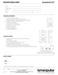
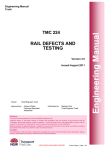
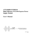
Break-Out Box
User Manual
www.opal-rt.com
Published by
Opal-RT Technologies, Inc. 1751 Richardson, suite 2525 Montreal, Quebec, Canada H3K 1G6
www.opal-rt.com
© 2011 Opal-RT Technologies, Inc. All rights reserved
Printed in Canada


CONTENTS
BREAK-OUT BOX.................................................................................................................. 4
INTRODUCTION................................................................................................................. 4
Features.......................................................................................................................................... 4
PIN ASSSIGNMENTS ........................................................................................................ 5
Front Low Current Connector Diagram........................................................................................... 5
Rear High Current Connector Diagram.......................................................................................... 6
Low Current Connector Pin Assignments....................................................................................... 7
High Current Connector Pin Assignments...................................................................................... 9
SPECIFICATIONS............................................................................................................. 10
Break-Out Box User Guide 3
Break-Out Box

BREAK-OUT BOX
INTRODUCTION
The Opal-RT break-out box lets you quickly and easily test electronic equipment. Using the OP8xxx
breakout box, you manually generate circuit faults (open circuit and short circuit) using jumpers to
Break-Out
Box
either break contact or connect a circuit. can
analyze
and test electronic equipment by specifically
Use
testing each component and its connection.
Break-Out Box
Controller
Simulator
Figure 1: Break-out box use illustration
By installing the break-out box as a link between the unti under test (ECU, motor controller, etc.) and
the simulator, you can insert a fault at any point in the test to assess how the unit reacts to the fault.
Features
• Up to 104 low current circuits (1, 3, 5, 8 amp)
• Separate plug in modules (Group of 8)
• Up to 18 high current circuits(10, 15, 20 amp)
4
Break-Out Box User Guide
Break-Out Box
Pin Asssignments
PIN ASSSIGNMENTS
Front Low Current Connector Diagram
Each pair of jacks connects from a channel on the unit under test to a channel on the simulator.
BREAKOUT BOX REAR VIEW
BREAKOUT BOX FRONT VIEW
B
D
C
E
F
H
J
K
M
L
N
P
1
1
1
1
1
1
1
1
1
1
1
1
1
2
2
2
2
2
2
2
2
2
2
2
2
2
3
3
3
3
3
3
3
3
3
3
3
3
3
4
4
4
4
4
4
4
4
4
4
4
4
4
5
5
5
5
5
5
5
5
5
5
5
5
5
6
6
6
6
6
6
6
6
6
6
6
6
6
7
7
7
7
7
7
7
7
7
7
7
7
7
8
8
8
8
8
8
8
8
8
8
8
8
8
A
B
C
D
E
F
H
J
A
B
C
D
E
F
H
J
K L M N P R S T V
U W X Y Z AA AB AC
AD AE AF AH AJ AK AL AM AN
AP AR AS AT AU AV AW AX
AY AZ BA BB BC BD BE BF BH
K L M N P R S T V
U W X Y Z AA AB AC
AD AE AF AH AJ AK AL AM AN
AP AR AS AT AU AV AW AX
AY AZ BA BB BC BD BE BF BH
BJ BK BL
BR BS BT
BJ BK BL
BR BS BT
BM BN BP
BU BV BW
BM BN BP
BU BV BW
BX BY BZ
CA CB CC
CD CE CF CH CJ CK CL CM CN
CP CR CS CT CU CV CW CX
CY CZ DA DB DC DD DE DF DH
DJ DK DL DM DN DP DQ DR
BX BY BZ
CA CB CC
CD CE CF CH CJ CK CL CM CN
CP CR CS CT CU CV CW CX
CY CZ DA DB DC DD DE DF DH
DJ DK DL DM DN DP DQ DR
DS DT DU DV DW DX DY DZ EA
DS DT DU DV DW DX DY DZ EA
EB EC ED EF EH EJ EK EL
EB EC ED EF EH EJ EK EL
RED
BLACK
A
ELCO Connector
female 120 pins
Figure 2: Front banana jacks path to ELCO connector
Faults are manually created by inserting a jumper into the desired channel jacks. The jumper used for
the break-out box are supplied.
In the event that replacements are needed, we recommend using the original part
(SKS2-12L/1SA/N, 12mm jumper, 2mm), or an equivalent.
Break-Out Box User Guide 5
Break-Out Box
Pin Asssignments
Rear High Current Connector Diagram
BREAKOUT BOX FRONT VIEW
HIGH CURRENT CONNECTOR
BREAKOUT BOX REAR VIEW
HIGH CURRENT CONNECTOR
BLACK
RED
Figure 3: High current banana jack path to Phoenix connector
6
Break-Out Box User Guide
Break-Out Box
Pin Asssignments
Low Current Connector Pin Assignments
The following table lists the signals available on the front, low current connector and on the system’s
two rear ELCO connectors.
Red (left)
Red (right) ELCO
breakout pin
connector
A1
A
A2
B
A3
C
A4
D
A5
E
A6
F
A7
H
A8
J
B1
K
B2
L
B3
M
B4
N
B5
P
B6
R
B7
S
B8
T
C1
U
C2
V
C3
W
C4
X
C5
Y
C6
Z
C7
AA
C8
AB
D1
AC
D2
AD
D3
AE
D4
AF
D5
AH
D6
AJ
D7
AK
D8
AL
E1
AM
E2
AN
E3
AP
E4
AR
E5
AS
E6
AT
E7
AU
E8
AV
F1
AW
F2
AX
F3
AY
F4
AZ
F5
BA
F6
BB
F7
BC
F8
BD
H1
BE
H2
BF
H3
BH
Break-Out Box User Guide Black (right)
breakout pin
A1
A2
A3
A4
A5
A6
A7
A8
B1
B2
B3
B4
B5
B6
B7
B8
C1
C2
C3
C4
C5
C6
C7
C8
D1
D2
D3
D4
D5
D6
D7
D8
E1
E2
E3
E4
E5
E6
E7
E8
F1
F2
F3
F4
F5
F6
F7
F8
H1
H2
H3
Black (left)
Signal Name / Channel
ELCO connector (space reserved for user notes)
A
B
C
D
E
F
H
J
K
L
M
N
P
R
S
T
U
V
W
X
Y
Z
AA
AB
AC
AD
AE
AF
AH
AJ
AK
AL
AM
AN
AP
AR
AS
AT
AU
AV
AW
AX
AY
AZ
BA
BB
BC
BD
BE
BF
BH
7
Break-Out Box
Pin Asssignments
Red (left)
breakout pin
H4
H5
H6
H7
H8
J1
J2
J3
J4
J5
J6
J7
J8
K1
K2
K3
K4
K5
K6
K7
K8
L1
L2
L3
L4
L5
L6
L7
L8
M1
M2
M3
M4
M5
M6
M7
M8
N1
N2
N3
N4
N5
N6
N7
N8
P1
P2
P3
P4
P5
P6
P7
P8
Red (right) ELCO
connector
BJ
BK
BL
BM
BN
BP
BR
BS
BT
BU
BV
BW
BX
BY
BZ
CA
CB
CC
CD
CE
CF
CH
CJ
CK
CL
CM
CN
CP
CR
CS
CT
CU
CV
CW
CX
CY
CZ
DA
DB
DC
DD
DE
DF
DH
DJ
DK
DL
DM
DN
DP
DR
DS
DT
Black (right)
breakout pin
H4
H5
H6
H7
H8
J1
J2
J3
J4
J5
J6
J7
J8
K1
K2
K3
K4
K5
K6
K7
K8
L1
L2
L3
L4
L5
L6
L7
L8
M1
M2
M3
M4
M5
M6
M7
M8
N1
N2
N3
N4
N5
N6
N7
N8
P1
P2
P3
P4
P5
P6
P7
P8
Black (left)
Signal Name / Channel
ELCO connector (space reserved for user notes)
BJ
BK
BL
BM
BN
BP
BR
BS
BT
BU
BV
BW
BX
BY
BZ
CA
CB
CC
CD
CE
CF
CH
CJ
CK
CL
CM
CN
CP
CR
CS
CT
CU
CV
CW
CX
CY
CZ
DA
DB
DC
DD
DE
DF
DH
DJ
DK
DL
DM
DN
DP
DR
DS
DT
Table 1: Low current connector pin assignments
8
Break-Out Box User Guide
Break-Out Box
Pin Asssignments
High Current Connector Pin Assignments
The following table lists the signals available on the front, low current connector and on the system’s
two rear ELCO connectors.
Red (left)
breakout pin
1
2
3
4
5
6
7
8
9
10
11
12
13
14
15
16
17
18
Red (right)
Pheonix
connector
Top
Top
Top
Top
Top
Top
Middle
Middle
Middle
Middle
Middle
Middle
Bottom
Bottom
Bottom
Bottom
Bottom
Bottom
Black (right)
breakout pin
1
2
3
4
5
6
7
8
9
10
11
12
13
14
15
16
17
18
Black (left)
Pheonix
connector
Top
Top
Top
Top
Top
Top
Middle
Middle
Middle
Middle
Middle
Middle
Bottom
Bottom
Bottom
Bottom
Bottom
Bottom
Signal Name / Channel
(space reserved for user notes)
Table 2: High current connector pin assignments
Break-Out Box User Guide 9
Break-Out Box
Specifications
SPECIFICATIONS
Product name
Break-Out Box
Part number
OP8xxx
Number of channels
Low current: 104 channels, 1A, 3A, 5A (or 8A TBD)
High current: 18 channels, : 10A, 15A, (or 20A TBD)
Voltage range
0-30 Vdc
Form factor
3U
Dimensions
13.33 x 48.26 x 30.8cm HxWxD (5.25” x 19” x 12.125”)
I/O connector
Low current: Elco 120 pin, SEB2-R 2 mm banana jack with 12 mm jumper
High current: Phoenix connector, SEB4-R 4mm banana jack with 19 mm jumper
Operating temperature
10 to 40 ºC (50 to 104ºF)
Storage temperature
-55 to 85ºC (-67 to 185ºF)
Relative humidity
10 to 90%, non condensing
Maximum altitude
2,000 m (6562 ft.)
10
Break-Out Box User Guide
Break-Out Box
Specifications
Break-Out Box User Guide 11
CONTACT
Opal-RT Corporate Headquarters
1751 Richardson, Suite 2525
Montréal, Québec, Canada
H3K 1G6
Tel.: 514-935-2323
Toll free: 1-877-935-2323
Note:
While every effort has been made to ensure
accuracy in this publication, no responsibility can
be accepted for errors or omissions. Data may
change, as well as legislation, and you are strongly
advised to obtain copies of the most recently
issued regulations, standards, and guidelines.
This publication is not intended to form the basis
of a contract.
Technical Services
www.opal-rt.com/support
UG11-07039-OP1
02/2011
© Opal-RT Technologies Inc.