1
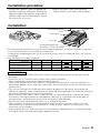
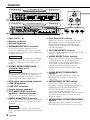
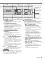
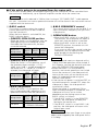
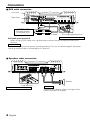
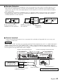
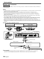
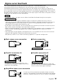
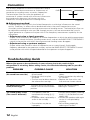
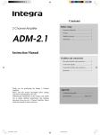
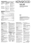
KAC-PS401M
MONO POWER AMPLIFIER
INSTRUCTION MANUAL
© B64-1441-00 (EM)
Safety precautions
2WARNING
To prevent injury or fire, take the following
precautions:
• When extending the ignition, battery, or
ground cables, make sure to use automotivegrade cables or other cables with a 5mm 2
(AWG10) or more to prevent cable
deterioration and damage to the cable
coating.
• To prevent a short circuit, never put or leave
any metallic objects (such as coins or metal
tools) inside the unit.
• If the unit starts to emit smoke or strange
smells, turn off the power immediately and
consult your Kenwood dealer.
• Do not touch the unit during use because the
surface of the unit becomes hot and may
cause burns if touched.
2CAUTION
To prevent damage to the machine, take the
following precautions:
• Be sure the unit is connected to a 12V DC
power supply with a negative ground
connection.
• Do not open the top or bottom covers of the
unit.
• Do not install the unit in a spot exposed to
direct sunlight or excessive heat or humidity.
Also avoid places with too much dust or the
possibility of water splashing.
• When replacing a fuse, only use a new one
with the prescribed rating. Using a fuse with
the wrong rating may cause your unit to
malfunction.
• To prevent a short circuit when replacing a
fuse, first disconnect the wiring harness.
NOTE
• If you experience problems during
installation, consult your Kenwood dealer.
• If the unit does not seem to be working right,
consult your Kenwood dealer.
Cleaning the unit
If the front panel gets dirty, turn off the power
and wipe the panel with a dry silicon cloth or
soft cloth.
2CAUTION
Do not wipe the panel with a hard cloth or a
cloth dampened by volatile solvents such as
paint thinner and alcohol. They can scratch the
surface of the panel and/or cause the indicator
letters to peel off.
Accessories
Part name
External
View
Number of
Items
Terminal cover
(Power terminal)
1
Self-tapping screws
(ø5 × 18 mm)
4
Installation procedure
Since there are large variety of settings and
connections possible according to applications,
read the instruction manual well to select the
proper setting and connection.
1. Remove the ignition key and disconnect the
negative - terminal of the battery to
prevent short circuits.
2. Set the unit according to the intended usage.
3. Connect the input and output cables of the
units.
4. Connect the speaker cables and sigma servo
feed back cables.
5. Connect the power cable, power control
cable and grounding cable following this
order.
6. Install the unit in the car.
7. Connect the negative - terminal of the
battery.
2
English
2CAUTION
• If sound is not output normally, immediately
turn power off and check connections. Be
sure to perform the sigma servo connection
correctly.
• Be sure to make correct connections of the
sigma servo terminals.
• Be sure to turn the power off before
changing the setting of any switch.
• If the fuse blows, check cables for shorts,
then replace the fuse with one of the same
rating.
• Check that no unconnected cables or
connectors are touching the car body. Do
not remove caps from unconnected cables
or connectors to prevent short circuits.
Installation procedure
• Connect the speaker cables to appropriate
speaker connectors separately. Sharing the
negative cable of the speaker or grounding
speaker cables to the metal body of the car
can cause this unit to fail.
• After installation, check that the brake
lamps, winkers, and wipers work properly.
Installation
Self-tapping screw
Air inlet
Cooling fan
Air inlet
,,,,,,,,,,,,,,,,,,,,,,,,,,,,,,,
,,,,,,,,,,,,,,,,,,,,,,,,,,,,,,,
,,,,,,,,,,,,,,,,,,,,,,,,,,,,,,,
,,,,,,,,,,,,,,,,,,,,,,,,,,,,,,,
,,,,,,,,,,,,,,,,,,,,,,,,,,,,,,,
,,,,,,,,,,,,,,,,,,,,,,,,,,,,,,,
,,,,,,,,,,,,,,,,,,,,,,,,,,,,,,,
,,,,,,,,,,,,,,,,,,,,,,,,,,,,,,,
,,,,,,,,,,,,,,,,,,,,,,,,,,,,,,,
,,,,,,,,,,,,,,,,,,,,,,,,,,,,,,,
,,,,,,,,,,,,,,,,,,,,,,,,,,,,,,,
,,,,,,,,,,,,,,,,,,,,,,,,,,,,,,,
,,,,,,,,,,,,,,,,,,,,,,,,,,,,,,,,,,,,,,,,,,,,,,,,,,,,,,,,,,,,,,,,,,,,,,,,,,,,,,
,,,,,,,,,,,,,,,,,,,,,,,,,,,,,,,,,,,,,,,,,,,,,,,,,,,,,,,,,,,,,,,,,,,,,,,,,,,,,,
,,,,,,,,,,,,,,,,,,,,,,,,,,,,,,,,,,,,,,,,,,,,,,,,,,,,,,,,,,,,,,,,,,,,,,,,,,,,,,
,,,,,,,,,,,,,,,,,,,,,,,,,,,,,,,,,,,,,,,,,,,,,,,,,,,,,,,,,,,,,,,,,,,,,,,,,,,,,,
,,,,,,,,,,,,,,,,,,,,,,,,,,,,,,,,,,,,,,,,,,,,,,,,,,,,,,,,,,,,,,,,,,,,,,,,,,,,,,
,,,,,,,,,,,,,,,,,,,,,,,,,,,,,,,,,,,,,,,,,,,,,,,,,,,,,,,,,,,,,,,,,,,,,,,,,,,,,,
,,,,,,,,,,,,,,,,,,,,,,,,,,,,,,,,,,,,,,,,,,,,,,,,,,,,,,,,,,,,,,,,,,,,,,,,,,,,,,
,,,,,,,,,,,,,,,,,,,,,,,,,,,,,,,,,,,,,,,,,,,,,,,,,,,,,,,,,,,,,,,,,,,,,,,,,,,,,,
,,,,,,,,,,,,,,,,,,,,,,,,,,,,,,,
,,,,,,,,,,,,,,,,,,,,,,,,,,,,,,,,,,,,,,,,,,,,,,,,,,,,,,,,,,,,,,,,,,,,,,,,,,,,,,
,,,,,,,,,,,,,,,,,,,,,,,,,,,,,,,,,,,,,,,,,,,,,,,,,,,,,,,,,,,,,,,,,,,,,,,,,,,,,,
,,,,,,,,,,,,,,,,,,,,,,,,,,,,,,,,,,,,,,,,,,,,,,,,,,,,,,,,,,,,,,,,,,,,,,,,,,,,,,
,,,,,,,,,,,,,,,,,,,,,,,,,,,,,,,,,,,,,,,,,,,,,,,,,,,,,,,,,,,,,,,,,,,,,,,,,,,,,,
,,,,,,,,,,,,,,,,,,,,,,,,,,,,,,,,,,,,,,,,,,,,,,,,,,,,,,,,,,,,,,,,,,,,,,,,,,,,,,
,,,,,,,,,,,,,,,,,,,,,,,,,,,,,,,,,,,,,,,,,,,,,,,
,,,,,,,,,,,,,,,,,,,,,,,,,,,,,,,,,,,,,,,,,,,,,,,,,,,,,,,,,,,,,,,,,,,,,,,,,,,,,,
,,,,,,,,,,,,,,,,,,,,,,,,,,,,,,,
Installation board, etc.
(thickness : 15 mm or more)
• Since the power amplifier has no parts which require operation, it can be installed at a position
away from the driver’s seat without any hindrances.
As generally accepted positions for its installation, places such as inside the trunk, etc. can be
considered.
• Use the extension cables. (Optional.)
Length
0.5m
1m
2m
4m
5m
6m
Type
RCA cable
CA-2SL
CA-12SL CA-22SL
CA-52SL
RCA cable (ø7mm)
CA-3WL CA-13WL CA-23WL
CA-53WL
RCA cable (ø12mm)
CA-5W
CA-15W
CA-25W
CA-45W
CA-65W
2CAUTION
• Do not install the unit under the carpet. Otherwise heat build-up occurs and the unit may be
damaged.
• Install this unit in a location which allows heat to easily dissipate.
Once installed, do not place any object on top of the unit.
• The surface temperature of the amplifier will become hot during use. Install the amplifier in a
place where people, resins, and other substances that are sensitive to heat will not come into
contact with it.
• This unit has cooling fans to decrease the internal temperature. Be careful not to block the
cooling fan openings when installing the unit. Blocking these openings will inhibit the cooling of
the internal temperature and result in malfunction.
• When making a hole under a seat, inside the trunk, or somewhere else in the vehicle, check
that there is nothing hazardous on the opposite side such as a gasoline tank, brake pipe, or
wiring harness, and be careful not to cause scratches or other damage.
• Do not install near the dashboard, rear tray, or air bag safety parts.
• The installation to the vehicle should securely fasten the unit to a place in which it will not
obstruct driving. If the unit comes off due to a shock and hits a person or safety part, it may
cause injury or an accident.
• After installing the unit, check to make sure that electrical equipment such as the brake lamps,
turn signal lamps and windshield wipers operate normally.
English
3
Controls
!
2
3
1
FUSE(15A×4 )
–
+
–
4
+
0.5
15
15
15
15
∑SERVO II
FEED BACK
SPEAKER OUTPUT
GND
BATT.
1
5
INPUT
SENSITIVITY (MIN)
2 3
4
5
50
200
LO PASS
FREQUENCY
LINE IN
L
GND
R
INFRASONIC
FREQ (Hz)
20 25
30
OFF
8 9 0
1 Fuse (15 A × 4)
2 Battery terminal
3 Ground terminal
4 SPEAKER OUTPUT terminals
As this unit accepts speakers with a
minimum impedance of 2 ohms, connect
speakers with 2-ohm or higher impedance
to these terminals.
2CAUTION
The rated input of the speakers should be
no less than the maximum output of the
amplifier. Otherwise malfunction may
result.
5 SIGMA SERVO FEED BACK
terminals (See p.11)
2CAUTION
Be sure to make proper connections to the
SIGMA SERVO FEED BACK terminals.
Incorrect connection may result in lack of
sound output or other malfunctions.
6 RCA cable ground lead terminal
7 LINE IN terminal
8 LINE OUT terminal
9 Power control terminal
0 EXT.AMP.CONT. (external
amplifier control) terminal
This controls the B.M.S. (See P.6).
! INPUT SENSITIVITY control
Adjust this control according to the pre-out
level of the centre unit connected to this
amplifier.
NOTE
Refer to “Specifications” on the centre
unit’s instruction manual about the pre-out
level.
English
BAND
REJECT
LPF
%
ON
OFF
ON
OFF
BAND
REJECT
LPF
B.M.S.
15
15
4
200
B.R.F.
FREQUENCY
INFRASONIC
FREQ (Hz)
P.CON EXT.AMP.CONT.
R
6 7
40
#
OUT
L
0.2
(MAX)
ON
OPEN/
B.M.S.
CLOSE B.M.S. (+6)
(REMOTE)
20 25
&
30
OFF
ON
^
OFF
ON
$
OFF
ON
@
@ Low Pass Filter switch
When this switch is set to ON, the bass is
boosted because the frequencies of the
lower frequency band than the cutoff
frequency set with the LPF FREQUENCY
control are output.
# LPF FREQUENCY control
Sets the cutoff frequency when the FILTER
switch is set to LPF.
$ BAND REJECT filter switch
When this switch is set to ON, frequencies
in the band set with the BAND REJECT
FREQUENCY control are rejected and
eliminated. The band rejection allows to
reduce resonance inside the vehicle
compartment and standing waves. (See
P.12)
% BAND REJECT FREQUENCY
control
Sets the rejection frequency when the
BAND REJECT switch is set to ON.
(See P.12)
^ INFRASONIC FILTER switch
When this switch is set to ON, the
inaudible, ultralow frequencies below the
frequency set with the INFRASONIC
FILTER FREQUENCY switch are cut off.
This improves the reproduction
performance of the speakers by eliminating
unnecessary oscillations which will not
become sound.
& INFRASONIC FILTER FREQUENCY
switch
Switches the cutoff frequency when the
INFRASONIC FILTER switch is set to ON.
*
(
COOLING FAN
COOLING FAN
AIR
INDUCTION
e Xc e l o n
OPERATION/PROTECTION
OPERATION/PROTECTION
POWER
OPEN/CLOSE
OPEN/CLOSE
B.M.S.
FREQUENCY
2
3
3
1
1
4
4
LOW VOLTAGE
LOW VOLTAGE
0.5
5
INPUT
SENSITIVITY (MIN)
0.2
(MAX)
0.5
50
100
5
INPUT
SENSITIVITY (MIN)
0.2
(MAX)
50
B.M.S.
50
OPERATION/PROTECTION
POWER
B.M.S.
FREQUENCY
2
)
COOLING FAN
AIR
INDUCTION
MONO POWER AMPLIFIER
200
LO PASS
FREQUENCY
40
200
B.R.F.
FREQUENCY
100
OPEN/CLOSE
B.M.S.
50
200
LO PASS
FREQUENCY
40
200
B.R.F.
FREQUENCY
@1
LOW VOLTAGE
B.M.S.
@2
* POWER indicator
This indicator glows when the unit's power
is turned ON.
( COOLING FAN indicator
When the unit's internal temperature rises,
the slide panel opens automatically and the
cooling fan is activated.
The cooling fan is also activated when the
slide panel is opened.
Whilst the cooling fan is in operation, the
COOLING FAN indicator blinks.
) OPERATION/PROTECTION
indicator
This indicator glows when the power
comes ON normally.
If the PROTECTION function is activated,
the indicator blinks or goes out.
LOW VOLTAGE indicator
@1
This indicator glows when the power
voltage falls below 11V (volts).
If the power supply voltage returns to full
after a voltage drop, this indicator will blink
to alert the user that a voltage drop has
occurred.
The number of blinks indicates the number
of times the voltage has dropped (up to a
maximum of 10).
B.M.S. indicator
@2
This indicator glows when the bass boost is
turned ON using the B.M.S. (See P.6).
■ PROTECTION function
This unit incorporates a protection function
which protects the main unit and speakers
from troubles. The unit stops to function
when the protection function is activated.
• When the OPERATION/
PROTECTION indicator blinks:
• A speaker cable may be short-circuited.
• A speaker output may be in contact with
the ground.
• The temperature of the internal parts may
be higher than 120°C (248°F)
• The fuse of this unit may be blown.
• The unit may be malfunctioning and
sending DC signal to the speaker output.
• The sigma servo connection may be
erroneous.
Cancelling: turn the accessory power
source (ACC) OFF, then back ON.
• When the POWER indicator and the
OPERATION/PROTECTION function
both go out:
• The fuse of this unit may be blown.
• When the LOW VOLTAGE indicator
glows or blinks:
• Is the battery exhausted?
• The car battery has a small capacity.
• If the battery cable is too thin or too long,
it will not be able to supply enough
power.
• Is the battery cable deteriorated?
NOTE
If indicators !9 to @2 light up in succession or
blink in unison, the system is in DEMO mode.
If this happens, cancel DEMO mode by
pressing the OPEN/CLOSE button.
English
5
B.M.S. (Bass Management System)
B.M.S.
1
B.M.S.
OPEN/
CLOSE B.M.S. (+6)
(REMOTE)
OFF
ON
2
OPERATION/PROTECTION
POWER
OPEN/CLOSE
B.M.S.
FREQUENCY
2
OFF
30
20 25
15
P.CON EXT.AMP.CONT.
COOLING FAN
AIR
INDUCTION
MONO POWER AMPLIFIER
INFRASONIC
FREQ (Hz)
ON
BAND
REJECT
B.M.S.
FREQUENCY
OFF
LPF
ON
OPEN/
B.M.S.
CLOSE B.M.S. (+6)
(REMOTE)
B.M.S.
50
100
3
GND
1
4
LOW VOLTAGE
OPERATION/PROTECTION
0.5
100
L
50
R
0.2
(MAX)
OUT
5
INPUT
SENSITIVITY (MIN)
3
B.M.S.
40
200
LINE IN
B.R.F.
FREQUENCY
OPEN/CLOSE
L
200
LO PASS
FREQUENCY
R
50
LOW VOLTAGE
B.M.S. indicator
B.M.S.
■ If the unit is not going to be operated from the outside:
1 B.M.S. switch
This boosts the bass, focusing mainly on
the frequency setting determined using the
B.M.S. FREQUENCY control.
• (REMOTE) OPEN/CLOSE or
(REMOTE) B.M.S. position:
When the switch is in this position, the
bass is not boosted.
Bass boost
Flat (OFF)
Operations using the
Slide panel
OPEN/CLOSE button
• B.M.S. (+6) position:
When the switch is in this position, the
bass is boosted by 6dB.
The B.M.S. indicator glows.
Bass boost
+6dB (ON)
Operations
using the
Slide panel
OPEN/CLOSE button
2 B.M.S. FREQUENCY control
When the B.M.S. switch is set to the
B.M.S. (+6) position, this control can be
used to adjust the central frequency that
you want to emphasise.
3 OPEN/CLOSE button
Each time you press this button, the slide
panel either opens or closes.
6
English
NOTE
• If the slide panel meets an obstacle whilst
sliding, the slide operation will be halted. If
this happens, remove the obstacle and then
press the OPEN/CLOSE button again.
• If the centre unit power is switched OFF, or
the vehicle engine is switched OFF, whilst
the slide panel is open, the slide panel will
then close automatically. The next time the
power is turned ON or the vehicle engine is
turned ON, the slide panel will return to its
original open state.
• If the B.M.S. switch setting is changed to
(REMOTE), the slide panel will close in
preparation for remote operation, even if the
EXT.AMP.CONT. terminal is not connected.
2CAUTION
Take care not to allow your finger or any other
object to be trapped by the slide panel whilst
it is sliding.
■ If the unit is going to be operated from the centre unit:
The amount of bass boost and the opening/closing of the slide panel can be controlled from
the centre unit. Additionally, up to 3 power amplifiers can be set at the same time.
NOTE
Kenwood centre units released in 1999 or later having an “EXT.AMP.CONT.” cable operate
this unit. Instructions on how to operate the centre unit will be found in the instruction manual
supplied with the centre unit.
1 B.M.S. switch
This switch is used to select the range of
control operations that can be carried out
from the centre unit.
When the bass boost is switched ON, the
B.M.S. indicator glows.
• (REMOTE) OPEN/CLOSE position:
When the switch is in this position, only the
opening/closing of the slide panel can be
controlled from the centre unit; the bass
cannot be boosted.
AMP
AMP
AMP
Centre unit
BASS
BASS
BASS
setting status
Flat
+6
+12
Bass boost
Flat (OFF)
Slide panel
CLOSE
OPEN
• (REMOTE) B.M.S. position:
When the switch is in this position, any of
the three bass boost settings — FLAT,
+6dB and +12dB — can be selected from
the centre unit. If "+6 dB" or "+12 dB" is
selected, the slide panel will open.
AMP
AMP
AMP
Centre unit
BASS
BASS
BASS
setting status
Flat
+6
+12
Flat
+6dB
+12dB
Bass boost
(OFF)
(ON)
(ON)
Slide panel
CLOSE
OPEN
• B.M.S. (+6) position:
When the switch is in this position, the
bass is boosted by 6dB, regardless of any
operation carried out from the centre unit.
AMP
AMP
AMP
Centre unit
BASS
BASS
BASS
setting status
Flat
+6
+12
Bass boost
+6dB (ON)
Operations using the
Slide panel
OPEN/CLOSE button
2 B.M.S. FREQUENCY control
This control allows you to use the B.M.S. to
adjust the central frequency that you want
to emphasise.
3 OPEN/CLOSE button
• When the B.M.S. switch is in the B.M.S.
(+6) position, the slide panel will open or
close each time the button is pressed.
• When the B.M.S. switch is set to the
(REMOTE) position, the centre unit will
control the slide panel.
If you want to adjust the control inside the
slide panel, you can open/close the slide
panel temporarily by pressing the
OPEN/CLOSE button.
NOTE
• If the slide panel meets an obstacle whilst
sliding, the slide operation will be halted. If
this happens, remove the obstacle and then
press the OPEN/CLOSE button again.
• When the B.M.S. is in the (REMOTE)
position, and control operations are carried
out on the centre unit, the slide panel will
return to the status set on the centre unit
even if it is opened/closed using the
OPEN/CLOSE button.
• If the centre unit power is switched OFF, or
the vehicle engine is turned OFF, when the
slide panel is open, the slide panel will
automatically close.
When the power is turned back ON, or
when the vehicle engine is turned ON, the
slide panel will carry out an action
depending on the setting status of the
B.M.S. switch, as follows.
* If the B.M.S. switch is in the (REMOTE)
position, the slide panel will obey the
setting on the centre unit.
* If the B.M.S. switch is in the B.M.S. (+6)
position, the slide panel will return to its
original open state.
2CAUTION
Take care not to allow your finger or any other
object to be trapped by the slide panel whilst
it is sliding.
English
7
Connection
■ RCA cable connection
Left input
LINE IN
OUT
L
Right input
L
GND
P.CON EXT.AMP.CONT.
R
INFRASONIC
FREQ (Hz)
R
15
20 25
30
OFF
BAND
REJECT
ON
OFF
ON
LPF
OFF
B.M.S.
ON
OPEN/
B.M.S.
CLOSE B.M.S. (+6)
(REMOTE)
ON
LIN
E
IN
D
GN
P.C
L
R
CENTRE UNIT
(Cassette receiver,
CD receiver, etc.)
RCA cable *
RCA cable ground terminal
* : Commercially available parts
RCA cable ground terminal
When using an RCA cable with a ground lead attached, connect the ground lead to this
terminal.
2CAUTION
Do not use this terminal for power source grounding. This unit will be damaged if the power
source grounding cable is connected to this terminal.
■ Speakers cable connection
FUSE(15A×4 )
GND
∑SERVO II
FEED BACK
SPEAKER OUTPUT
–
+
–
+
15
15
15
15
BATT.
Speaker
Lead terminal *
* : Commercially available parts
8
English
NOTE
Distribute the speaker cables and sigma servo
cables along the same paths.
■ Speaker Selection
• The rated input power of the speakers that are going to be connected should be greater than
the maximum output power (in Watts) of the amplifier. Use of speakers having input power
ratings that are less than the output power of the amplifier will cause smoke to be emitted as
well as damage.
• Use speakers that have an impedance of 2Ω or greater. When more than one set of speakers
are going to be used, calculate the combined impedance of the speakers and then connect
suitable speakers to the amplifier.
1200W
(2Ω)
600W
(4Ω)
600W
(2Ω)
1200W
(2Ω)
(600W/4Ω) 4 Ω
Rated input power and
impedance of the speakers
(600W/4Ω)
4Ω
Maximum output of
the amplifier
300W
(8Ω)
1200W
(2Ω)
600W
(2Ω)
300W
(8Ω)
(600W/4Ω)
4Ω
Combined
impedance
■ Control terminal
Attach the connection terminal to a commercially available wiring cable for in-car use, and
connect it to the unit.
NOTE
An EXT.AMP.CONT. terminal can only be attached if Kenwood centre unit is a model released in
1999 or latter, and has an “EXT.AMP.CONT.” cable. Using the external amp control, up to 3
power amplifiers can be operated simultaneously (although this may not be possible, depending
on the type of wiring cable used, and its length).
Power control lead terminal
LINE IN
L
External amplifier control terminal
OUT
L
GND
P.CON EXT.AMP.CONT.
R
INFRASONIC
FREQ (Hz)
R
15
20 25
30
Power control cable
(Blue/ White)
CENTRE UNIT
(Cassette receiver,
CD receiver, etc.)
GN
BAND
REJECT
ON
OFF
D
P.C
ON
OFF
ON
EX
T.A
MP
LPF
OFF
.CO
NT
B.M.S.
ON
OPEN/
B.M.S.
CLOSE B.M.S. (+6)
(REMOTE)
.
P.CONT.
EXT.AMP.
CONT.
External amplifier control
cable (Pink / Black)
Extension cable *
Lead terminal *
* : Commercially available parts
English
9
Connection
■ Power cable connection
2WARNING
To prevent fire caused by a short in the wiring, connect a fusible link or breaker nearby the battery’s
positive terminal.
Wiring
• If a buzzing noise is heard from the speakers when the engine is running, connect a line noise filter
(optional) to each of the battery cable.
• Do not allow the cable to directly contact the edge of the iron plate by using Grommets.
• Connect the ground cable to a metal part of the car chassis that acts as an electrical ground
passing electricity to the battery‘s negative - terminal. Do not turn the power on if the ground
cable is not connected.
• Please be sure to install a protective fuse in the power cable, near the battery. Use a fuse which
has a capacity about 10A higher than the capacity of the fuse in the unit.
• For the power cable and the earth cable, use (flame-resistant) power wiring cables for in-car use.
For the power cable, use a power wiring cable with a current capacity about 10A higher than the
capacity of the protective fuse (about 20A higher than the capacity of the fuse in the unit).
• When more than one power amplifier are going to be used, use a power supply wiring cable and
protective fuse of greater current-handling capacity than the total maximum current drawn by each
amplifier.
Example: One Power Amplifier Is Used
Fuse capacity
Protective Fuse
Cross-sectional Area of Wiring
Cable (AWG)
60 A
5 mm2 (AWG 10) or greater × 1
25 A
25 A
75 A
25 A
25 A
FUSE(15A×4 )
GND
SPEAKER OUTPUT
–
+
25 A
∑SERVO II
FEED BACK
–
+
15
15
15
15
BATT.
25 A
Lead terminal *
Power terminal
Terminal cover
Battery cable *
Ground cable *
Lead terminal *
Protective
Fuse
Battery
* : Commercially available parts
Power terminal
Pass battery and ground cables through supplied terminal cover and connect to respective
terminals. After completing connections, fasten terminal cover over terminal bracket.
10
English
Sigma servo feed back
The sound reproduced through conventional amplifiers is distorted due to the
counterelectromotive force produced in the oscillating system of the speaker. The
counterelectromotive force is particularly high with the woofer which requires a large drive
mass.The sigma servo connection reduces distortion caused by the counterelectromotive force
by including the circuit up to the speaker terminals in the negative feedback loop. This makes it
possible to drive speakers with more fidelity to the input signals and create a sharp bass sound
image with few feeling of noise interference.
NOTE
The speaker cables and sigma servo cables should be distributed along the same paths.
2CAUTION
• The extension of the negative feedback loop to include the speaker terminals makes it
necessary to connect the sigma servo terminals correctly. Incorrect connection may result in
sound degradation or other malfunction. If sound is not reproduced normally, check the
connection of the sigma servo terminals, etc.
• If the Sigma servo terminals are not connected, the sound may fluctuate or noise may occur.
Be sure to connect the Sigma servo terminals correctly.
• When connecting speakers in a parallel configuration, use speakers with an impedance of 4
ohms or more. Connecting speakers with smaller impedance than 4 ohms will cause
malfunction.
• The rated input of the speakers connected to this unit should be no less than the maximum
output of the amplifier. Otherwise malfunction may result.
Be specially careful in this when connecting speakers in a parallel configuration.
■ Basic sigma servo connection
■ Series connection
2CAUTION
Make this cable as short as possible.
■ Parallel connection (1)
■ Parallel connection (2)
2CAUTION
The speaker cables connected to this unit
should be thick enough to supply the current
capacity of two speakers.
2CAUTION
This connection is possible only when the
speakers are identical and the speaker cables
are also of the same type and length.
■ Simplified sigma servo connection
In case any of the connection examples above cannot be
used or if the speakers cannot be connected to the speaker
terminals, connect them to this unit as shown in the figure.
English
11
Connection
The acoustic properties of vehicle compartment tend to
cause oscillation due to resonance or unclearness of
sound due to standing waves at certain frequencies.
The band reject filter can solve the problems of
resonance or unclear sound with minimum influence on
the sound quality because it eliminates only the
frequencies causing resonance or standing waves.
0 dB
Frequency
■ Adjustment method:
The band reject filter cuts only the limited frequencies to minimize influence on the sound
quality. Therefore, its effect cannot be obtained unless the cutoff frequencies are set
accurately to the frequencies causing resonance and standing waves. The band reject filter can
be adjusted according to what you feel through your ears, but we recommend the use of a
signal generator or a spectrum analyzer with a fine frequency measurement capability for the
adjustment.
• Adjustment using a signal generator:
Output a sine wave, vary its frequency to find the frequencies at which the vehicle compartment
resonates or volume increases (standing waves occur), and set the BAND REJECT FREQUENCY
control to the position with which the resonance and standing waves disappear.
• Adjustment using a spectrum analyzer:
Output white noise (sound in which all frequencies are at a certain level), find the peak
frequency observed on the spectrum analyzer, and set the BAND REJECT FREQUENCY control
to the position with which the peak observed on the spectrum analyzer disappears.
Troubleshooting Guide
What might appear to be a malfunction in your unit may just be the result of slight
misoperation or miswiring. Before calling service, first check the following table for possible
problems.
PROBLEM
POSSIBLE CAUSE
SOLUTION
No sound.
(No sound from one side.)
• Input (or output) cables are
• Connect the input (or output)
disconnected.
cables.
• Protection circuit may be
• Check connections by referring
activated.
to "Controls".
• The fuse may be blown because • Replace the fuse with a new
the volume was too high.
fuse and use a lower volume.
The output level is too
small (or too large).
The input sensitivity adjusting
control is not set to the correct
position.
Adjust the control correctly
referring to “Controls”.
The sound quality is bad.
(The sound is distorted.)
• The speakers cable are
connected with wrong + / polarity.
• A speaker cable is pinched by a
screw in the car body.
• Connect them properly checking
the + / - of the terminals and
cables well.
• Connect the speaker cable again
so that it is not pinched by
anything.
• Set switches properly by
referring to "Controls".
• The switches may be set
improperly.
12
English
Troubleshooting Guide
PROBLEM
If the slide panel moves of
its own accord.
POSSIBLE CAUSE
• The system is in DEMO mode.
• The slide panel has gone into
remote operation mode.
The external amplifier
controller (B.M.S.) will not
work.
• The B.M.S. switch is set to
"B.M.S. (+6)".
• The external amplifier control
cable has come loose.
SOLUTION
• Cancel DEMO mode by pressing
the OPEN/CLOSE button.
• Check the B.M.S. and operate
the slide panel remotely or
manually.
• The B.M.S. switch is set to
"(REMOTE)".
• Check that the external amplifier
control cable is properly
connected.
Specifications
Specifications subject to change without notice.
Audio Section
Max Power Output (2 Ω) ....................................................................................................1200 W × 1
Rated Power Output (+B = 12.0 V)
(4 Ω) ..................................................................................200 W × 1 (20 Hz ~ 20 kHz, 0.05 % THD)
(2 Ω) ....................................................................................................400 W × 1 (1 kHz, 0.5 % THD)
Rated Power Output (+B = 14.4 V)
(4 Ω) ........................................................................................300 W × 1 (DIN : 45324 , +B = 14.4V)
(2 Ω) ....................................................................................................600 W × 1 (1 kHz, 0.5 % THD)
Frequency Response (+ 0 , – 3 dB) ................................................................................5 Hz ~ 50 kHz
Total Harmonic Distortion (Rated power)# ....................................................................0.002 % (1 kHz)
Sensitivity (rated output) (MAX.) ..................................................................................................0.2 V
Sensitivity (rated output) (MIN.) ....................................................................................................5.0 V
Signal to Noise Ratio ..................................................................................................................105 dB
Input Impedance ..........................................................................................................................10 kΩ
Damping Factor ....................................................................................More than 9900 (at ∑ connect)
Low Pass Filter Frequency (24 dB/oct.) ..............................................................50 ~ 200 Hz (variable)
Infrasonic Filter Frequency (24 dB/oct.) ..................................................................15 / 20 / 25 / 30 Hz
Band Reject Filter Frequency ..............................................................................40 ~ 200 Hz (variable)
# Sensitivity = Mini. , Through LPF (30 kHz)
General
Operating Voltage ....................................................................................12.0 V (11 ~ 16 V allowable)
Current Consumption (4 Ω, +B = 12.0 V, 10 % THD) ....................................................................36 A
Dimensions (W × H × D) ........................................................................................272 × 64 × 380 mm
Weight..........................................................................................................................................7.0 kg
English
13