1
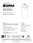
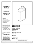
Kenmore
8EAR8
Water Softener
microMAX MODEL NO. 625.348460
-- WARRANTY m
START UP/SETTING TIMER
-- HOW IT WORKS -CARE OF-
SPECIFICATIONS
-- REPAIR PARTS --
SAVE THIS MANUAL
(Use plasticbag and tie provided,to hang manualsnearbythe softenerfor future reference).
PRmlrEDm U,8,A.
WARRANTY
SEARS RESIDENTIAL WATER SOFTENER
FULL ONE YEAR WARRANTY ON WATER SOFTENER
Forone year from the date of purchase, when this water softener is installed and maintained
in accordance with our instructions, Sears will repair, free of charge, defects in material or
workmanship in this water softener.
FULL TEN YEAR WARRANTY AGAINST LEAKS
For ten years from the date of purchase, Sears will furnish and install a new current model
water softener tank or salt storage drum, free of charge, if either the tank or drum develop
a leak.
TO OBTAIN WARRANTY SERVICE, SIMPLY CONTACT THE NEAREST SEARS SERVICE CENTER THROUGHOUT THE UNITED STATES. This warranty applies only while
this product is in use in the United States.
This warranty gives you specific legal rights, and you may have other rights which vary from
state to state.
Sears, Roebuck and Co., D/8!7 WA, Hoffman Estates, IL 60179
Ifyou want your water softener profession 811yinstalled, talk to your Sears Salesman. He will arrange for
a prompt, quality installation by Sears Authorized Installers.
SEARS INSTALLATION POLICY
SEARS INSTALLATION WARRANTY
All installation labor arranged by Sears shall be
performed in a neat, workmanlike manner in
accordance with generally accepted trade practices. Further, all installations shall comply with
all local laws, codes, regulations, and ordinances. Customer shall also be protected,
during installation, by insurance relating to
Property Damage, Workman's Compensation
and Public Uability.
In addition to any warranty extended to you on
the Sears merchandise involved, which warranty
becomes effective the date the merchandise is
installed, should the workmanship of any Sears
arranged installation prove faulty within one
year, Sears will, upon notice from you, cause
such faults to be corrected at no additional cost
to you.
FACTS AND FIGURES TO KEEP
Fill in the blanksbelow and keep this book in a safe
place so you always have these facts.
Water Softener Model No.'i'.
Sedal Number
Date Installed
Water Hardness
Grains Per Gallon
Iron Content
Parts Per M,lion
*pH
TasteAnd/Or Odor
Water Pressure
Pounds/SquareInch
Water Flow
Gallons Per Minute
1"The model number is on the ratingdecal, located
on the rim, under the salt hole cover.
TABLE OF CONTENTS
PAGE
NO.
SECTION 1
A.
B.
C.
D.
E.
SOFTENER
WORKS
14
15
16
17
OTHER THINGS TO KNOW
18
SERVICER'S TECH INFORMATION
TROUBLESHOOTING
ROTARY VALVE SERVICE
WATER FLOW THROUGH THE SOFTENER VALVE
SECTION 6
10
11-13
CARE OF YOUR SOFTENER
DIMENSIONS/SPECIFICATIONS
SECTION 5
A.
B.
C.
WATER
SALT...REFILLING STORAGE TANK, SALT BRIDGE
KEEPING THE WATER SOFTENER CLEAN
KEEP THE SOFTENER FROM FREEZING
HELPFUL HINTS CHECKLIST
SECTION 4
A.
HOW YOUR
FACE PLATE TIMER FEATURES
SOFT WATER SERVICE AND REGENERATION
SECTION 3
A.
B.
C.
D.
4
5
6-7
8
9
SAFETY GUIDES
CHECK LIST OF STEP-BY-STEP GUIDES TO INSTALL
PROGRAM THE TIMER
SANITIZING THE WATER SOFTENER
FILL THE STORAGE TANK WITH SALT
SECTION 2
A.
B.
SOFTENER START UP
REPAIR
PARTS
3
19-22
23
24-26
29-31
SECTION 1
I
wATER
SOFrE.ER
START-UP
I
I
I
1A.
SAFETY GUIDES
• Read all steps, guides and rules carefully before installing and using your new water softener.
Follow all steps exactly to correctly install. Failure to follow them could cause personal Injury or
property damage. Reading this book will also
help you to get all of the benefits from your water
softener.
• Your water softener will remove hardness minerals and "clear water" iron from water, up to the
limits shown on page 18. It will not remove other
types of iron, acids, tastes and odors, etc. It will
not purify polluted water or make it safe to drink.
• Protect the softener and piping from freezing.
Damage from freezing voids the softener warranty. See page 16.
CAUTIONS
PLEASE READ AND COMPLY WITH THE FOLLOWING GUIDES TO PREVENT DAMAGE TO
THE SOFTENER OR OTHER PROPERTY,
PERSONAL INJURY, OR POSSIBLE FATAL
SHOCK.
• THIS SOFTENER WORKS ON 24 VOLTS
ONLY. BE SU RE TO USE THE TRANSFORMER
INCLUDED, AND PLUG IT INTO A 120V OUTLET.
• Unplug the transformer right away if the
power cable should beoome damaged or
frayed. Make repairs before plugging back
into the power outlet.
• Always unplug the softener from electrical
power before removing outer valve covers.
IMPORTANT: Salt is used to recharge the mineral In your
water softener...ese page 9. Before shipping, the mineral
is factory pmtreated with call Before using water from
this softener, be sure to do the sanitizing procedures and
start a recharge (page 8), to flush salt from it.
4
SECTION
1
WATER SOFTENER
START-UP
I
|
lB.
CHECK LIST OF ALL STEP-BY-STEP GUIDES TO INSTALL
Refer to the Installation Manual,
7141417, for step-by-step guides.
part
no.
To be sure you have done all the steps to install
the softener, read the following list. Page numbers referred to are in the Installation Manual.
v' Is the house water flow going INTO the softener valve INLET? Trace piping to be sure...
pages 10 and 11.
i/
_ VALVE
INLET
Is the plumbing bypass valve (or 3 valves) set
for SERVICE?...page 18.
v' Is the valve drain hose connected the right
way, and without sharp bends or kinks that
could stop or reduce water flow?...page 16.
Is the softener power cable connected to the
transformer...and is the transformer plugged
into an inside. 120V-60Hz electrical outlet...
page_
v' Be sure to restart the water heater...page 20.
5
SECTION 1
WATER
sOrrE.ER
START-UP
t
I
1C.
PROG,RAM THE TIMER
UP buaon
DOWN
button
F
m
lmNla=m=_
(_\
ON/OFF - HOLD butto_
(RECHARGE TONIGHT-
I
I
II_"_
_l"_e"
•e p4p_
el
.e
J
SELECT butlon
NOW)
1. SET PRESENT TIME OF DAY:
NOTE:
When the transformer is plugged in, the model
code SC21 shows in the face plate display for a
few seconds, followed by a test number (example: $4.0). After the test number, 12:00 AM
begins to flash. PRESENT TIME and RECHARGE TONIGHT show at the bottom of the
display.
m_
•
--"'--"
ifthe words... PRESENT TiME do not show in
the display, press the SELECT button (FIG.
1) until they do.
• Press the [;_IUP/DOWN _]buttons to set the
present time. Press UP to move the display
ahead; press DOWN to move the time backward.
.
•
,=e tme
i,
noon and midnight, be sure PM
shows.
NOTE:
w,
If SC - - flashes in the display, press the UP
button (FIG. 1) until SC21 does show. Then
press the SELECT button to display the flashing
12:00 AM. IF OTHER THAN SC21 SHOWS
when the transtormer ts pluggeo in, please see
page 1/ to reset.
If the present time is between
l= =,_,p"
midnight and noon, be sure AM t_s=_ _,=
shows.
NOTE:
Each press of the UP/DOWN buttons changes
the time by 1 minute. Holding the buttons in
changes the time 32 minutes each second.
SOUND =BEEPER': A =beeper" sounds while
pressing buttons for timer set-up. One beep
signals a change in the face plate display.
Repeated beeps means the timer will not accept
a change from the button you have pressed,
telling you to use another button. For example,
while setting the hardness (step 2), the beeper
sounds repeatedly when the display reaches 1
using the DOWN button, or the highest hardness
setting using the UP button.
6
SECTION 1
WATER
SOFTENER
STAnT-UP
I
1C.
PROGRAM
THE TIMER
2. SET WATER HARDNESS NUMBER:
• Press the SELECT button once to display
15 (flashing) and HARDNESS.
At the 2:00 AM RECHARGE
i
TIME setting, the softener be_._,_t_,._.
gins regeneration (see pages 11 "=_=P_,_"
and 12) at 2:00 AM, ending no
later than 4:00 AM. This is a good time in most
households because water is not being used
(see AUTOMATIC BYPASS, page 13). If a
different RECHARGE TIME setting would be
better for your household, do the following.
t
The grains per gallon (gpg)
hardness of your water supply is
on your water analysis report.
Be sure to enter water test
results on page 2, for future reference.
NOTE:
• Press the {_UP/DOWN _buttons to set the
desired RECHARGE starting hour. Be sure to
observe the AM-PM as you did when setting the
present time of day.
If your water supply contains iron, compensate
for it by adding to the water hardness number.
For example, assume your water is 15 gpg hard
and contains 2 pprn iron. Add 5 to the hardness
number for each I ppm of iron. In this example,
you would use 25 for your hardness number.
2 ppm iron x 5 = 10
(times)
NOTE:
Each press of the UP/DOWN buttons changes
the display 1 hour. Holding the buttons in
changes the display twice each second.
• PRESS THE SELECT BUTTON ONCE
AGAIN, to return the present time (steady) of day
an RECHARGE TONIGHT in the display.
15 gpg hardness
+10
25 HARDNESS NUMBER
• Press the _UP/DOWN _outtons to set your
water hardness number in the display. The
DOWN button moves the display to 1. The UP
button moves the display to the highest setting
(see maximum setting for your model in the
specifications).
4. SET"CLEAN"FEATURE:
• PresstheSELECTbuttonag_n.Thedi_
play _tem_ss
between "CLEAn",
"OFF" _efau_.
and
ICLE"°II11 I
NOTE:
Each press of the UP/DOWN buttonchanges the
display by I between 1 and 25. Between 25 and
the highest number, the display changes 5 at a
time...25, 30, 35, etc. Holding the UP or DOWN
button in changes the display twice each second.
When set to "CLEAn"/"ON", a backwash is assured after every 500 gallons of water usage.
Backwash is described on page 12. This cleaning backwash is in addition to the backwash dup
ing recharge. If you have iron in the water supply,
or higher amounts of sediments (sand, siR, dirt,
etc.) you should set this feature to ON.
• To set to ON, or to turn off if already on, press
either the UP or DOWN button once. The length
of this extra backwash is 1 minute (default time
setting).
3. SET RECHARGE (REGENERATION) TIME:
• Press the SELECT button once to display
2:00 AM (flashing) and RECHARGE TIME.
SEE PAGE 10 FOR OTHER FACE PLATE TIMER FEATURES.
IMPORTANT: Salt is used to recharge the mlneral In your water softener...see page 9. Before
shlpplng, the mineral Is factory pretreated with sail Before using water from this softener, be
sure to do the sanitizing procedures and start a recharge (page 8), to flush salt from It.
7
SECTION 1
WATER
SOFTENER
START-UP
,11
II
!
I
ID.
SANITIZING THE WATER SOFTENER
Care is taken at the factory to keep your water
softener clean and sanitary. Materials used to
make the softener will not infect or contaminate
your water supply, and will not cause bacteria to
form or grow. However, during shipping, storage,
installing and operating, bacteria could get into
the softener. For this mason, sanitizing as
follows is suggested ® when installing.
ADD WATER
Bdns_a
""
Cover
(B_ve a_l add
about3/4 ¢=.blea_)
1. Lift the salt hole cover and use a pail or hose
to till the salt storage tank with at least 1
gallon of water.
2. Remove the brinewell cover (FIG. 2) and
pour about 3/4 ounce of common 5.25%
household bleach (Clorox, linco, BoPeep,
White Sail, Eagle, etc.) in the softener
brinewelL
""
adnelt_l
3. Press the ON/OFF-HOLD buttonand holdfor
3 seconds to start a recharge. This first
recharge does several things.
It draws the bleach into and through the
softener to sanitize it.
Recommendedbythe Water QualityAssociation.On
somewater supplies,the watersoftenermay need periodicdisinfecting.Sanitize with or withoutsalt in the
storagetank.
It fills the salt tank to the water level
needed.
It gets all the air out of the resin tank.
--
It makes the resin bed (see page 11)
ready for service.
NOTE:
This recharge takes about 40 minutes.
8
SECTION 1
WATER
SO E.ERSTART-UP
I
1E.
FILL THE STORAGE TANK WITH SALT
Brine (salt dissolved in water) is needed for each
and every regeneration. The water for making
bdne is metered into the salt storage tank by the
softener. However, you must keep the tank filled
with salt.
ADD SALT
Fill the tank with NUGGET or PELLET water
softener salt. DO NOT use rock salts, as they
have dirt and sediments that will stop the
softener from working.
Before filling, be sure the brinewell cover is in
place on the top of the brinewell. Salt storage
capacity is shown on page 18.
Cover
NOTE:
In humid areas, it is best to fill the storage tank
half-full, and to refill it more often. Salt bridging
(see page 14) occurs more often when conditions are humid.
WATER ,SOFTENING SALT WITH IRON REMOVING ADDITIVES -- Some salts have an
additive to help the softener handle iron in the
water supply. Although this additive may help to
keep the softener resin clean, it may also release
corrosivefumes that will weaken and shorten the
life of some softener parts.
SODIUM INFORMATION: Water softeners using sodium chlodde for regeneration add sodium
to the water. Persons who are on sodium
restricted diets should consider the added sodium as part of their overall sodium intake.
For example, if your water supply is 15 grains
hard, you would have to drink 3 quarts of
softened water to consume 335 milligrams of
sodium. That is equivalent to eating 2-1/2 slices
of white bread.
Persons who are concemed about their ddnking
water should consider a Sears Drinking Water
System that will remove or reduce in excess of
90% of the sodium and other drinking water
contaminants.
YOU HAVE NOW FINISHED THE WATER SOFTENER START-UP. AFTER THE SANITIZING RECHARGE, ON PAGE 8, THE SOFTENER WILL BE GIVING YOU SOFT WATER.
9
SECTION 2
.owYOUR
WATER
SO E.ERWORKS
I
2A.
FACE PLATE TIMER FEATURES
EXTRA RECHARGE
Sometimes, a manually started regeneration
(recharge) may be desired, or needed. Two
examples are...
PROGRAM MEMORY
If electrical power to the softener goes off, the
time display is blank but the face plate timer
keeps the correct time for about 6 hours. When
electrical power comas on again, you have to
reset the present time only if the display is
flashing. The HARDNESS and RECHARGE
TIME never require resetting unless a change is
desired.
...You have used more water than usual (guests
visiting) and you may run out of soft water before
the next timer started regeneration.
...You did not refillthe softener with salt before it
was gone.
Even if the timer is incorrect after a long power
outage, the softener works as it should to keep
you water soft. However, regenerations may
occur at the wrong time of day untilyou reset the
timer to the correct time of day.
You can start a regeneration right away, or you
can set the timer to regenerate at the next 2:00
AM (or other preset recharge time). Do the
following.
ERROR CODE
An error code could appear in the face plate
display if a problem occurs in the softener
electronics. If you see an error
RECHARGE NOW
• Press the ON/OFF-HOLD button and hold
for 3 seconds. The softener
enters the fill cycle of regen-,
eration right away...the dis- _' # m__0
play shows "Filling NOW". r! i !
Th s regeneration will last for
about 40 minutes. Then, you
will have soft water again.
code
instead
of the
time IEI'I"
of day,
please
callpresent
you local
Sears Service Department for
service.
0
SOFTENER STATUS DISPLAY
1. SERVICE ( PROVIDING SOFT r
WATER) POSITION: The display|"
shows the present time of day. IfJ
"TURBINE" is gashing,soft water
iscurrentlyin use.
RECHARGE TONIGHT
• Press and release (DO NOT HOLD) the
CHARGE TONIGHT flashes
ON/OFF-HOLD button. RE-_=_
in the display, and the softener begins regeneration at the
next preset recharge time. Press and release
the ON/OFF-HOLD button once more if you
decide to cancel the regeneration, and RECHARGE TONIGHT.
_:1._
M
]
_-- I
2. RECHARGE POSmONS:
A. Fill Cycle- Filling NOW shows "--'
I
in the display.If softwater is being F! / I i ,_g
used,_'URBINE" gashes.
B. BRINING, BACKWASH AND
FAST RINSE CYCLES - The displayshewsthe minutesof recharge
,,.=p= ,,,,..,
remainingbeforeretum to soft waI_" J_:U_
ter service. RECHARGE NOW is _
tow
also gashing.
I
10
SECTION 2
2B.
HOW
YOUR
WATER
sO rENER
WORKS
SOFT WATER SERVICE AND REGENERATION
SERVICE
REGENERATION
ITIFILL: Salt, dissolved in water, is called brine.
Brine is needed to clean the hardness minerals
from the resin beads. To make the brine, water
flows into the salt storage area during the fill
stage as shown in FIG. 5. Fill cycle length
depends on how much soft water making
capacity you have used since the last regeneration. It fillslonger, the more water you have used,
and makes more brine. The greater amount of
brine cleans more hardness minerals from the
resin bed.
When the softener is giving you soft water, it is
called "Service". During service, hard water
comes from the house main water pipe into the
softener. Inside the softener resin tank is a bed
made up of thousands of tiny, plastic resin beads
(FIG. 4). As hard water passes through the bed,
each bead attracts and holds the hardness
minerals. This is called ion-exchanging. It is
much like a magnet attracting and holding
metals. Water without the hardness minerals
(soft water) flows out of the softener and intothe
house soft water pipes.
WATER FLOW THROUGH THE
)FTENER IN FILL
After a period of time, the resin beads become
coated with hardness minerals and they have to
be cleaned. This cleaning is called regeneration
or recharge. Regeneration isstarted at 2:00 a.m.
by the electronic timer (see page 13). It takes
place in 5 stages or cycles. These are:
_1
[_]
FILL
BRINING
BRINE RINSE
_WATER
Hard Water
IN
Soft Water
OUt
_
151 BACKWASH
FAST RINSE
Salt
a Tanl_
(salt not shown)
FLOW THROUGH THE
SOFTENER IN SERVICE
Hard Water
IN
OUT
Bed
Tank
11
SECTION 2
How YOUR WATER SOFTENER WORKS
I
I
2B.
SOFT WATER SERVICE AND REGENERATION
r2-1BRINING: During brining, the brine is moved
from the sail storage area, into the resin tank.
inside the resin tank, brine cleans hardness
minerals from the resin beads and they are
discharged out the drain. How much brine is
needed to clean the resin depends on...
WATER FLOW THROUGH THE
'SOFTENER IN BACKWASH
Hard Water
iN
Hard Water
BYPASS
.
...the amount of resin in the softener,
...how fast the brine goes through the bed.
The nozzle and venturi (FIG. 6) make suction to
take brine from the salt tank and put it into the
resin tank. It keeps the brine flow down to a very
slow rate to get the best resin cleaning with the
least sail
and expa
[]]BRINE RINSE: After all of the brine goes into
the resin tank, the brine valve closes. Water
keeps flowing the same way it did during brining
except the brine flow has stopped. Hardness
minerals and brine flush from the resin tank to the
drain. Brining and brine dnse together vary in
length relative to the fill cycle length.
mFAST RINSE: Backwash is followed by a fast
flow of water down through the resin tank. The
fast flow packs the resin bed and gets it ready for
retum to service (FIG. 8).
WATER FLOW THROUGH
THE
SOFTENER
IN BRINING AND
BRINE RINSE
After fast rinse, the softener returns to service.
Hard water goes into the resin tank where the
resin bed again takes out the hardness minerals.
Soft water goes to the house soft water pipes.
Hard Water
IN
WATER FLOW THROUGH THE
"R IN FAST RINSE
BYPASS
Venturi
Soft Water
OUT
I_IBACKWASH: During backwash, water flows
UP through the resin tank (FIG. 7) at a fast rate to
flush iron minerals, dirt and sediments from the
bed and to the drain. The bed lifts and expands
for good cleaning.
12
Hard Water
IN
SECTION 2
2B.
HOW YOUR WATER SOFTENER
WORKS
SOFT WATER SERVICE AND REGENERATION
AUTOMATIC BYPASS
[] COMPUTER m The computer is part of the
circuit board. It is programmed to know the
softener's capacity (how many grains of hardness minerals itwill take out ofthe water before a
regeneration is needed). When starting the
softener, page 7, you set it for the grains per
gallon (gpg) hardness of the water.
During the brining, brine rinse and backwash
cycles of regeneration, HARD water goes
through the softener valve and to the house
pipes. If a faucet is opened, hard water is there
for your needs. However, you should not use
HOT water, ifpossible, because the water heater
will refill with hard water. The softener regenerates from 2:00 AM to about 2:40 AM, (you can
change this time...see
page 7), a time when
water is usually not in use.
The computer uses, (1) water usage from the
meter, (2) hardness setting, (3) softener capacity, and (4) time since the last regeneration, to
find a regeneration pattern best for your needs.
The computer always adjusts this pattem to your
water using habits. It works toward providingyou
with soft water for the longest _me and the most
efficient salt usage.
If you get up early in the morning and you can
hear the softener regenerating, change the time
setting. Set the recharge time to 12:00 AM or
1:00 AM. Then regeneration will start and end
that much earlier and your water heater will not
refillwith hard water if a hot faucet is opened.
As hard water goes through the softener and
hardness minerals are removed, capacity is
used. When the computer determines only
enough capacity remains to provide soft water
up to the next regeneration starting time (2:00
AM, or as otherwise set), it will schedule a
regeneration. RECHARGE TONIGHT displays
until the regeneration begins. When the regeneration begins, the recharge cycle status displays show...see page 10.
Two main parts of the softener's electronics are
m a WATER METER, and [] a COMPUTER.
[] WATER METER -- The water meter is in the
softener valve outlet. As water flows through the
meter, it sends electric pulses to the computer.
The computer changes the pulses to a measure
in gallons of water.
13
SECTION 3
3A.
CARE
OFYOUR
SO rE.ER
SALT...REFILLING STORAGE TANK/BREAKING A SALT BRIDGE
WHEN TO REFILL WITH SALT: Check the salt
level a few weeks after you install the softener
and every week after that. Refill when the
stora_oe tank is about 113 full. Never let the
softener use all the salt before refilling. Without
salt, you will soon have hard water.
IMPORTANT:
YOU WILL HAVE A LOSS IN SOFTENING
CAPACITY AND MAY GET PARTLY HARD
WATER IF LESS THAN 10 INCHES OF SALT IS
IN THE STORAGE TANK.
PLEASE SEE PAGE 9 FOR SALT FILLING DIRECTIONS.
SALT BRIDGE
Sometimes, a hard crust or salt bridge forms in
the salt storage tank. It is usually caused by high
humidity or the wrong kind of sail When the salt
bridges, an empty space forms between the
water and salt. Then salt will not dissolve (melt)
in the water to make brine. Without brine, the
resin bed does not regenerate and you will have
hard water.
If the wrong kind of salt made the bddge, take it
out. Then fill the tank with nugget or pellet salt
only.
SALT BRIDGE
If the storage tank is full of salt, it is hard to tell if
you have a salt bridge. Salt is loose on top, but
the bridge is under it. The following is the best
way to check for a salt bridge.
1;2"
Pem_i
Salt should be loose all the way to the bottom of
the tank. Hold a broom handle, or like tool, up to
the softener as shown in FIG. 9. Make a pencil
mark on the handle, 1" or 2" below the top height
of the rim. Then, carefully push it straight down
into the salt. If a hard object is felt before the
pencil mark gets to the top of the tank, it's most
!ikely a salt bddge. Carefully push intothe bddge
in a few places to break it. DO NOT TRY TO
BREAK THE SALT BRIDGE BY POUNDING ON
THE OUTSIDE OF THE SALT TANK. YOU MAY
DAMAGE IT.
Bmom H_dle _
14
,Salt
SECTION 3
CARE
OFYourSOFTENER
I
I
3B.
KEEPING THE WATER SOFTENER CLEAN
NOTE:
COVERS
To keep your new Sears water softener looking
nice, apply a coat of paste wax and repeat once a
year. When dusty, wipe it with a clamp cloth to
keep it sparkling.
Never use cleaners having ammonia or abrasives. They may scratch and dull the surface.
NOZZLE AND VENTURI
CLEANING THE NOZZLE & VENTURI
A clean nozzle and venturi (FIG. 10) isa must for
the softener to work right. This small unit moves
brine from the salt storage tank to the resin tank
during regeneration. If it becomes plugged with
sand, silt, dirt, etc., the softener will not work and
you will get hard water.
To get to the nozzle and ventufi, remove the
softener top cover. Be sure the softener is in
service cycle (no water pressure at nozzle and
venturi), then turn off the cap from the nozzle and
venturi housing. DO NOT LOSE THE LARGE
O-RING SEAL Lift out the screen support and
screen, then the nozzle and venturi. Wash and
rinse the parts in warm water until clean. If
needed, use a small brush to remove iron or dirt.
Also check and clean the gasket and small
screen.
Venturi
Gasket
Screen
"Flow Plug
(HVOC)
"INSTALL WITH
NUMBERED SIDE UP
• CONCAVE SIDE DOWN.
Carefully replace all parts in the correct order.
Lubricate the o-ring seal with silicone grease or
Vaseline and place in position. Install and tighten
the cap, BY HAND ONLY. DO NOT OVERTIGHTEN AND BREAK THE CAP OR HOUSING.
IRON FROM THE RESIN BED
Your water softener takes hardness minerals
(calcium and magnesium) out of the water. Also,
it can control some =clear water" iron...see
maximum allowed in the specifications on page
18. With clear water iron, water from a faucet is
clear when first put into a glass. After 15 to 30
minutes, the water begins to cloud or turn rust
colored. A water softener WILL NOT remove any
iron which makes the water cloudy or rusty as it
comes from the faucet (called red water iron). To
take red water iron out of water, or over the
maximum of Clear water iron, an iron filter or
other equipment is needed. Your local Sears
store has trained people to help you with iron
water problems.
If your water supply has clear water iron, even
though less than the maximum allowed, regular
resin bed cleaning is needed. Sears has resin
bed cleaner, Stock No. 42-,34426 for this. Clean
the bed at least every 6 months. If iron shows up
in the soft water before 6 months, clean more
often. Printed instructions are on the resin bed
cleaner bottle.
15
SECTION 3
CARE
OFYOUR
SOFTENER
III
I
II
3C.
KEEP THE SOFTENER FROM FREEZING
Ifthe softener is installed where it could freeze
(summer cabin, lake home, etc.), you must drain
all weter from it to stop possible freeze damage.
To drain the softener
_DRAIN
WATER FROM THE
SOFTENER
1. Close the shut-off valve on the house main
water pipe, near the water meter or pressure
tank.
2. Open a faucet in the soft water pipes to vent
pressure in the softener.
Floor'_l
Drain
3. Looking at FIG. 12 on page 18, move the
stem in a single bypass valve to bypass.
Close the inlet and outlet valve in a 3-valve
bypass system, and open the bypass valve. If
you want water in the house pipes again,
reopen the shut-off valve on the main water
pipe.
7,
Looking at FIG. 11, lay a piece of 2 inch thick
board near the floor drain. Move the softener
close to the drain. SLOWLY and CAREFULLY tip it over until the rim rests on the wood
block with the inlet and outlet over the drain.
DO NOT ALLOW THE SOFTENER'S
WEIGHT TO REST ON THE INLET AND
OUTLET FITTINGS OR THEY WILL BREAK.
8,
Tip the bottom of the softener up a few inches
and hold until all water has drained. Leave
the softener laying like this untilyou are ready
to use it. Plug the inlet and outlet with rags to
keep dirt, bugs, etc. out.
4. Unplug the transformer at the wall outlet.
Remove the salt hole cover and the main
cover. Take off both drain hoses.
5. Carefully remove the large holding clips at
the softener Inlet and outlet (see Key No. 61,
on page 30). Separate the softener from the
adaptors or bypass valve.
6. Remove the bdnewell cover and disconnect
the brine valve tubing at the nozzle and
venturi assembly (see page 23). Lift the brine
valve out of the bdnewell. Tip the brine valve
upside down to drain out water.
16
r\ WoodIJock
SECTION 3
CARE
OFYOUR
SO ENER
I
3D.
HELPFUL HINTS CHECKLIST
... TO HELP YOU SAVE MONEY
If your water softener fails to work, make the following easy checks. Often, you will find what's wrong
yourseff and you won't have to cell and wait for service. If, after making the checks, your softener still
does not work right, call your Sears Service Department.
NOTE:
Also read ERROR CODE, page 10. If an error code is notdisplayed, press and holdthe SELECT button
until(example:000 --) shows in the display. Then press SELECT again and hold untilan SC code appears. It must show SC21. If any other SC number shows, the softener computer is working on incorrect input and would probably be the cause of the problem. To set SC21, press either the UP _ or
DOWN [_]button. Then, press select to retum a flashing 12:00 AM display, and reset the timer, page 6.
PROBLEM
CAUSE
CORRECTION
WATER HAS SALTY Softener not recharged immediately See IMPORTANT note, pages 4 and 7. Usa the RETASTE
after installation.
CHARGE NOW feature to start an immediaterecharge,
and open softwater faucetsto purgesalttaste.
Lost electric power during a recharge.
NO SOFT WATER
Restorepower, resettimerif needed,and opensoftwater
faucets to purge salt taste.
No salt in storage tank, or sail Refillwith sail,or break the salt badge(page 14). Usethe
badged.
RECHARGE NOW feature to starta recharge.
Transfomer unplugged at the wall Check for loss of power due to any ofthese and correct.
outlet, or power cable leads loose, Withthe powerbackon, lookat thetime displayand read
fuse blown,circuitbreakerpopped, or PROGRAM MEMORY, page 10.
circuitswitchedoff.
Manual bypass valve(s) in bypass Lookat FIG. 12 on page 18. Move the stem in a single
position,
valve to service. In a 3-valve bypass,openthe inlet and
outletvalves, and be sureto fullyclosathabypess valve.
Dirty, plugged or damaged nozzle & Take apart and clean or replace damaged parts (see
ventud,
page 15).
Valve drain hose plugged.
WATER HARD SOMETIMES
The drain hose mustnot have kinks,sharpbends, or be
raised to high above the softener (see page 16 in your
installationmanual).
Hardness numbersettingtoo low.
Using hot water when softeneris regenerating,
Press and release the SELECT buttonuntilHARDNESS
! shows in the display.Read the hardnessnumber in the
I displayand be sure the same grainsper gallonnumber
is shownon yourwater analysis report.See page 7 to reset. Pressand release the SELECT buttonuntilthe present time shows in the display.
Avoid usinghotwater duringthis time becausethe water
heater refills with hard water (see Automatic Bypass,
page 13).
Increase in the grains of hardness in Ask your Sears retail store for a new water analysis.
j your water supply.
Then make a new hardnessnumber seffing(page 7).
17
SECTION 4
OT.ER
T.INQS
TOKNOW
I
I
4A.
DIMENSIONS/SPECIFICATIONS
BYPASS VALVES
SINGLE-PLASTIC
SINGLE-BRASS
/--)
PULL STEM
OUTWARD
FOR
SERVICE
I
__
I
\
I
:..-8-.J'
Push
TIE
C
9-VALVE
D
Bypass
ValVe
Inlet
Valve
\
A
B
Salt Tank Height
ResinTank Diameter (nominal)
C
ResinTank Height (nominal)
D
E
Inlet-OutletHeight
Overall Height
F1 Length
F2 Wio'th
--
Distancebetween inlet-outlet
center lines
21-3/4
10
55.2
25.4
21
53.3
22-1/2
27-1/2
57.2
69.9
19-1/2
16-1/2
49.5
41.9
3-3/8
8.6
MODEL NO. 625.348460
TIMER SC CODE SC21
NOTE:
Please see the rating decal for water softener operating capacity, salt usage and service flow rate/preP
sure loss performance specifications. Performance specifications are validated by the Water Quality
Association (WQA). The rating decal is located on the rim, under the salt hole cover (see page 28).
WATER
SUPPLY
TO WATER
OTHERS
SOFTENER
MINIMUM WATER SYSTEM FLOW (gpm)
MINIMUM-MAXIMUM WATER PRESSURE (psi')
MAXIMUM WATER TEMPERATURE (°F)
MAXIMUM WATER HARDNEss (gpg)
MAXMUM "CLEARWATER" IRON (ppm)
3
20-120
120
70"
10
SALT FOR WATER SOFTENER
TYPEOF SALTNEEDED
Nugget/Peaet
ALTERNATE
TYPE OF SALT Pure,evaporated,
compacted
watersoftenersalt
STOI_AGECAPACITY(pounds)
125
"Do not excmeclthis number when setling hardness in step 2,
page 7. The maximumseffingavailable is 95.
18
TYPE OF ION EXCHANGE MATERIAL(resin) High Capacity
AMOUNT OF RESIN (cu.ft.)
.60
REGENERATION (RECHARGE) CYCLE TIME (rain.)
FILL
1- 5
BRINING/BRINE RINSE
28
BACKWASH
1
FAST RINSE
1
TOTAL REGENERATION TIME
31 - 35
gpm,, gallonsperminute
geg. grainspar gallon
psi. paundsI_ squareinch
ppm= pads par miUion
SECTION 5
5A.
SERVICER'S
TECH. INFORMATION
TROUBLESHOOTING
KEEP THIS MANUAL WITH YOUR WATER SOFTENER. IF REPAIRS ARE NEEDED, THE SERVICE
TECHNICIAN MUST HAVE THE INFORMATION ON THE FOLLOWING PAGES.
WIRING SCHEMATIC
24VAC
NC
tt
NO
DOWN
UP bumm
,/
N
ON_DFF- HOUDburn
SELECTimuan
z
5. The valve drain hose mustbe free of Idnksand sharp
bends, and not elevated over 8 ft. above the floor.
ALWAYSMAKE THESE INmAL CHECKS FIRST
1.
Does the time display showthe correct Ume of day?.
REMOVE THE TOP COVER AND SALT TANK COVER
...If display is blank, check power source to the
soRener.
...If time is flashing, powerwas off for over 6 hours.
The softener resumes normaloperation but regenerations occurat the wrong time.
...If an error code (Example: Err 03) shows in the face
plate display, go to AtJTO_C
ELECTRONIC
DIAGNOSTICS.
2. Plumbing bypass valve(s) must be in Full Service
position.
3.
6. istheresaltin thestoragetank?
7.
Is the brine tubing connected? (See water flow
diagrams).
8.
Isthe brine valve float set right?(See page 22).
9,
The inletand outletpipesmustconnect tothe softener
inlet and outletrespectively.
4. Isthe transformerpluggedinto a qive", groundedwall
Press the SELECT button 2 times to display the
hardnesssetting.Be sureitisthe correct settingfor the
households watersupply.(Make8 hardnesstest of the
rawwater and compere withthe hardnesssetUng.Also
test a soft water sampie to verify if a problemexlsts.]l
Press SELECT 3 times to ratum the present time
display.
ffyou do notitnd theproblemaftermakinginitialchecks,do
the MANUAL INmATED ELECTRONIC DIAGNOSTICS,
and the MANUAL ADVANCE REGENERATION CHECK.
outlet, and the power cable fastened securely?
19
SECTION 5
SERVlCER'S
TECH.
I..ORMATION
5A.
AUTOMATIC
TROUBLESHOOTING
ELECTRONIC DIAGNOSTICS
The chart below shows the error codes that could
appear, and the possible defects for each code.
The face plate computer has a self-diagnostic
function for the electrical system (except input
While an error code appears in the display, all
face plate buttons are inoperable except the
SELECT button. The SELECT button remains
operational so the service person can make the
MANUAL INITIATE ELECTRONIC DIAGNOSTICS to further isolate the defect, and check the
water meter.
computer monitors the electronD-_
power and water meter). The Erlr"
I
ic components and circuits for
correct operation. If a malfunction occurs, an
error code appears in the face plate display.
POSSIBLE DEFECT
CODE
Err
Err
Err
Err
Err
01
02
03
04
05
MOST LIKELY
_
_
LESS LIKELY
motor inop. / widncj hamass or connection to switch / position switch / face plate
face plate
motor inop. / face plate
face plate / position switch
face plate
PROCEDURE FOR REMOVING ERROR CODE FROM FACE PLATE: 1. Unplug transformer 2. Correct defect
3. Plug-in transformer 4. Wait for 6 minutes. The error code will retum if the defect was not corrected.
MANUAL
NOSTICS
INITIATED
ELECTRONICS
DIAG_
MOTOR
1. To enter diagnostics, press and hold the
SELECT button until (000 - -) shows in the
display.
PosmoN
plnnn___"l
""'
swn'c.
!1
i .._._td_'_....,.--.-'I'URB|NE
A. tionThe
asfirstfollows:3
digits indicate water meter opera-
_
000 (steady)= soft water not in use...no
flow through the meter.
--OPEN A NEARBY SOFT WATER FAUCET000 to 199 (continual) = repeats display for
each gallon of water passing through the meter.
S%P_AND
VALVE
It_k_A)'
OUTLET----.--,_/
B. The letter (P) and dash(as) indicate POSITION switch operation. The letter appearing
means the switch is closed; the dash means
the switch is open.
If you don't get a reading in the display, with
faucet open, pull the sensor from the valve
outlet porL Pass a small magnet back and
forth in front of the sensor. You should get a
reading in the display. Ifyou get a reading, unhook the in and out plumbing and check the
turbine for binding.
Use the ON/OFF-HOLD (Recharge Now)
button to manually advance the valve into
each cycle and check correct switch opera_on.
20
SECTION 5
SERVICER'S
TECH.
INFORMATION
I
5A.
CORRECT
SWITCH
DISPLAYS
TROUBLESHOOTING
For this model, the AUTO RECHARGE display must show. If anything other than AUTO
shows, press a UP or DOWN button until it
does show.
VALVE CYCLE STATUS
Valvein service,fill, brining,
backwash orfast rince position
_p
4. Press SELECT once again to display12 hr,TIME.
Valve rotating from one posi-
tion to another
c. While in this diagnostic screen, the following
I 112
information is available and may be beneFIcial for various reasons. This information is
retained by the computer from the first time
electrical power is applied to the face plate.
77_11--I
[2Hbir']
At this setting, display times are shown in
standard clock time. If set to 24 hr, using the
UP or DOWN button, display times will be in
military time, 0100 (1:00 AM) to 0000 (midnight).
... Press _to display the number of days this
face plate has had electrical power applied.
5. Press the SELECT button and hold 3 seconds until...
...Press _o display the number of regenera'donsinitiated by this face plate since the SR
code number was entered.
COOE
...SC21
2. Press Select to advance to the following
aitemating displays.
shows.
5E2
This code identifies the softener nominal capacity size. If the wrong number shows, the softener
will operate on incorrect programming. Do the
following as needed.
I ' I
RETURN THE PRESENT TIME DISPLAY - press
the SELECT button.
This setting controls the length of the backwash cycle (regular recharge backwash, and
the CLEAN feature backwash if setto ON). A
longer backwash is beneficial if supply water
is dirty, or contains iron. The time is adjustable up to 5 minutes. Use the UP or DOWN
button to set.
(_HANGE THE SR NUMBER - press the UP or
DOWN button to display correct number;, press
SELECT, and reset the timer.
NOTE:
If the face plate isleft ina diagnosticdisplay(or a flashing
I display when settingtimes or hardness), present time
Iautomaticallyreturnsif a button is not _
within4
minutes.
3. The next press of the SELECT button displays an AUTO RECHARGE screen.
21
SECTION 5
SERV,CER'S
TECH.
I.FOR.ATION
!
I
5A.
TROUBLESHOOTING
MANUAL ADVANCE REGENERATION CHECK
This check verifies proper operation of the valve
motor, brine tank fill, brine draw, regeneration
flow rates, and other controller functions. ALWAYS MAKE THE INITIAL CHECKS, AND THE
MANUAL INITIATED DIAGNOSTICS.
NOTE: If water system pressure is low, an
elevated drain hose may cause back pressure,
stopping brine draw.
3. Again press ON/OFF-HOLD to move the
softener into backwash. Look for a fast flow of
water from the drain hose.
NOTE: The face plate display must show a
steady time (not flashing).
A. An obstructed flow indicates a plugged backwash flow plug, drain hose, filter screen, or
top distributor.
1. Press the ON/OFF-HOLD button and hold in
for 3 seconds. RECHARGE NOW begins to
flash as the softener enters the fill cycle of
regeneration. Remove the brinewell cover
and, using a flashlight, observe fill water
entering the tank.
CAUTION: Do Not remove the top distributor
from the resin tank. Loss of water softening
resin will occur. See bottom of page 28.
4. Press ON/OFF-HOLD to move the softener
into fast rinse. Again look for a fast drain flow.
Allowthe softener to rinse for a few minutes to
flush out any brine that may remain in the
resin tank from the brining cycle test.
A. If it does not enter the tank, look for an obstructed nozzle, venturi, flu flow plug, brine
tubing, or brine valve riser pipe.
5. To return the softener to service, press
ON/OFF-HOLD.
CYCLE FLOW RATES (GALLONS PER MIN.)
FILL (flOWto salt storage tank) 0.3 (1.1 liters)
BRINING
_
.35 (1.3 liters)
BACKWASH
BRINE
RINSE
FAST RINSE
1.8 (0.8
(6.8 liters)
liters)
/ (flow to drain) .22
1.8 (6.8 liters)
N
2. After observing fill, press the ON/OFF-HOLD
button to move the softener into brining. A
slow flow of water to the drain will begin.
Verify brine draw from the brine tank by
shining a flashlight into the brinewell and
observing a no_ceable drop in the liquid level.
NOTE: Be sure a salt bridge is not preventing
water with salt contact.
A, If the softener does not draw brine...
...nozzle and/or venturi dirty or defective.
...nozzle and ventufi not seated properly on
gasket.
...restricted drain (check drain fitting and
hose).
...defective nozzle and venturi seal.
...other inner valve defect (rotor seal, rotor&
disc, wave washer, etc.).
22
SECTION 5
SERVICER'S
TECH. INFORMATION
I
I
5B.
ROTARY VALVE SERVICE
BEFORE WORKING ON THE VALVE, TURN
OFF THE WATER SUPPLY AND DISCONNECT
FROM ELECTRICAL POWER. TO RELIEVE
PRESSURE...
Lower the cover onto the valve body and rotor
shaft. Then instaJl the cover holding screws.
BEFORE
TIGHTENING
THE
SCREWS,
INSTALL THE VALVE CAM AND GEAR. THEN
TURN THE ROTOR (CLOCKWISE ONLY) TO
SERVICE POSITION. Tighten the screws using
a crisscross pattern. If a torque wrench is
available, torque to 30-40 inch pounds.
...3 VALVE BYPASS: Close the inlet valve and
open a soft water faucet. Then close the outlet
valve and open the bypass valve.
...SEARS SPECIAL BYPASS: Slide the bypass
valve stem to bypass posiUon.Loosen the 3 hex
head screws (see A in drawing) toward the
backside of the valve to allow pressure water to
bleed out (catch water with a rag).
Lubricate the gear on the motor, and the valve
cam gear with Molykote grease, or other high
quality gear lubricant.
Be sure to orient switch as shown, with lever
toward the cam.
T
'
To remove a part or group of parts, refer to the
valve drawing. A common screwdriver or nut
driver, Phillips screwdriver and pliers are the only
tools needed to completely disassemble.
SERVICING THE VALVE
-
Inspect all o-rings, seals and gaskets for wear or
defects.
Inspect the bottom surface of the rotor and disc
for scratches, chips or wear.
NOTE: If replacement is needed, be sure to use
the current replacement bart.
Be sure all parts are in place and in the proper
position. Lubricate ALL o-rings and seals with
FDA approved silicone grease. To install the
rotor seal, first place the seal into the valve
groove, rounded side down (see cross-section).
Apply a light coating of silicone grease to the
seal's crossing ribs. Then, carefully center the
wear strip on the seal, and push it downward
onto the seal.
Install the nozzle and venturi seal and drain seal.
Assemble 2 o-dngs and the wave washer onto
the rotor and diSC.Then center the rotor and disc,
in the valve body, on the rotor seal.
NOTE:IFTOU NEEDTO
REMOVE THE VALVE
F'RON _
TANK, DO NOT REMOVE THE TOP DtS"rP4BUTOROR RESIN
LOSSWU.LOO_JR_
23
SECTION 5
SERVICER'S
TECH.
INFORMATION
II
I
I
5C. WATER FLOW THROUGH THE SOFTENER VALVE
SERVICE CYCLE
INLET
VALVEOUTLET
SWITCH
Hard water enters the valve inlet port. internal valve porting mutes the
water down and out the top distributor, into the resin tank. Hard water is
softened as it passes through the resin bed, then enters the bottom
distributor. Soft water flows back into the valve and out the valve outlet, to
the house soft water pipes.
FILL CYCLE
PoSmON
VALVECAM
ROTOR & DISC
SWITCH
VENTURI
PLUG
VALVE LNLETPOSITION
SWITCH
(SOFT)
VALVEOUTLET'
To begin a regeneration, the electronic Urner energizes the circuit to the valve
motor. The valve motor rotates the rotor and disc and the valve cam until the
position switch lever drops to open the motor circuit and position the valve in
FILL As the rotor and disc rotates, the port opens for SOFT water fill through
the ventud. RII flow continues to the brine valve, and into the salt storage tank.
Soft water is still evailable to the house lines.
24
SECTION 5
SERVlCSR'S
TECH.
INFORMATION
=,
!
5E. WATER FLOW THROUGH THE SOFTENER VALVE
BRINING
AND BRINE
RINSE CYCLES
ROTOR & DISC
VALVE
OUTLET
POS_TION
.=
BRINE
FROM SALT
STORAGE
TANK
RESIN
I_ ./
DISTRIBUTOR
After fill, timer/switch action allows the motor to tum the rotor and disc into
BRINING pos_on. Water flow is directed to the nozzle. Suction, created by _e
nozzle and venturi, draws brine from the salt storage tank and injects it into the
resin bed via the bottom distributor. Flow continues out the top distributor and to
the drain. Hard water is available at the valve outlet.
When the brine valve closes to end brine draw, water flow continues in the same
directions to slowly RINSE brine from the resin bed and to the drain.
BACKWASH
FLOW PLUG
ROTOR&DISC
INLET
OUTLET
(and "CLEAN")
CYCLE
"rimer/switch action again allows the motor to turn the
rotor & disc to place the valve in BACKWASH,
stopping water flow to the nozzle. Water is muted
down and out the bottom distributor, up through the
bed, and out the top distributor to the drain. The fast
flow (controlled by a flow plug in the drain fitting)
flushes dirt, sediments, iron deposits, remaining brine
and hardness to the drain.
PosrI'ION
DISTRIBUTOR
SWITCH
_
RESIN
BED
DISTRIBUTOR
25
SECTION 5
SERVICER'S
TECH.
INFORMATION
I
5E. WATER FLOW THROUGH THE SOFTENER VALVE
FAST RINSE CYCLE
ROTOR & DISC
POSITION SWITCH
DRAIN
VALVE
OUTLET
POSITION
SWITCH
DISTRIBUTOR
TOP
•
_@
/
"_"
_
BOTTOM
DISTRIBUTOR
During FAST RINSE, the rotor & disc is positioned so water flow
enters the resin tank through the top distributor, and exits through
the bottom distributor,to the drain.
The solid state timer again energizes the motor to retum the valve to
se_ice, and as the valve rotates, the position switch lever drops to
open the circuit. The valve remains positioned in service until the
timer initiates the next regeneration.
26
I
I
NOTES
27
SECTION 6
REPAIR
PARTS
SEARS WATER SOFTENER
MODEL NO. 625, 348460
VALVE
ASSEMBLY
3
I ASSEMBLY
SOFTENER
10
PART
NUMBER
1
7137604
Cover (main)
2
7137612
Salt Hole Cover
3
7118333
Wire Hamess (switch)
4
7084330
Power Cord (transformer)
7152913
Timer Repl. (PWA)
7137620
Face Plate (also order decal below)
7145568
Face Plate Decal
7
7137&99
Rim
8
7137727
BdnowellCover
9
7082150
Wing Nut, 1/4"
10
7106962
Bdnewell
11
7152963
Salt StorageTank
12
7143956
PlasticScrew, 1/4" x 5/8"
13
0900431
Hose ClampV
14
1103200
Hose AdaptorV
15
9003500
GrommetV
16
7145500
Brine ValveAssem. ( see page 29)
17
7152947
ResinTank Assembly(complete)WI
18
0900039
O-ring, 1-1/16" x 1-1/4"
19
0900215
O-ring, 13/16" x 1-1/16"
20
7150327
Filter Screen
21
7141001
VaporBarrier
22
7088041
Clamp Section(2 req.)
7088033
Clamp Retainer (2 req.)
DESCRIPTION
15
24
7095373
Transformer,24V-10VAy
14
•
7141417
InstallationManual
•
7145445
Owners Manual
16
•
_"
KEY
NO.
Includedin parts bag...see
page 31.
Consists ofall resintank partsincludingwatersoftening resin, inner distrioutors,and the filter screen, key no.
20. The assembly Is FACTORY SERVICEABLE ONLY.
[Tl•r
nOtillustrated
You
can replacethe o-rings and the ltlter screen,key nos.
18 - 20, but do not remove the top distributor or water
soReningresinloss will occur.
111 _
28
SECTION 6
REPAIR
PARTS
m
"--1
SEARS WATER SOFTENER
MODEL NO. 625.348460
ASSEMBLY
J BRINE
VALVE
r
44
INLET - OUTLET
GROUNDING CLAMPS
KEY
NO.
PART
NUMBER
30
0505957
Washer
31
0513860
FloatStop
32
7092317
Float
33
0516947
FloatSeal
34
7093216
Float Rod & Stem
35
7092278
Guide Cap
36
O9O0535
O-ring, 15/16"x 1-3/16'
37
0516211
Seal
38
0516924
Retainer,BottomSeal
39
7116713
Clip
40
7092252
BrineValve Body
41
7O8O653
Clip
42
7131365
Screen
43
7094979
Insert
-44
7092294
Retaining Ring
45
7092286
O-dng, 5/16" x 9/16"
46
7152989
BrineTube
47
7113016
TubingAasem. (Ind. Key No. 43,
44, &45)
48
7112997
GroundClamp K]tV
•
f48
29
DESCRIPTION
Included in parts beg...see
page 31.
SECTION
I
6
REPAIR
PARTS
,
!
SEARS WATER SOFTENER
MODEL NO, 625.348460
VALVE
58
TUBING
7s
i
75
74
73
30
59
6O
ASSEMBLY
SECTION 6
R PAIR
PARTS
I
SEARS WATER SOFTENER
MODEL NO. 625.348460
KEY
NO.
50
51
52
53
54
55
56
57
56
59
6O
61
62
63
64
65
66
67
68
69
7O
71
72
73
74
75
76
77
PART
NIMBER
7131755
7133008
0900857
7117808
O5O3288
7113927
7142942
0501228
O9OOO41
7024160
0900431
7116713
0507369
0507615
O9OO570
42-3441
2207800
O9OO535
7134224
7092634
7092642
7129889
7081764
7082053
09OOO64
7081201
7081104
1202600
7089267
42-3433
7147112
7129716
DESCRIPTION
Screw, #6-20 X 7/8' (2 req.)
Motor (incl. 2 ea. of Key No. 50)
Screw, #6-20 x 3/8" (2 red.)
Motor Plate
Baadng
Cam and Gear
Clip (drain)
Flow Plug
O-ring, 5/6, x 13/16,
Drain Hose Adaptor
Hose Clamp•
Clip (2 req.)V
InstaJletionNut (2 red.) PR
InstallationTube (2 req.) IT!
Washer (2req.) []
Install. WJt(Incl. Key No. 62- 64) WI
InstaReUonAdaptor(2 rsq.)[] •
O--ring, 15/16, x 1-3/16, (2 red.) •
Rotor Seal
O-ring, 3/6, x 9/16,
Plug (Drain Seal)
Spring
Seal (Nozzle & Ventud)
ValveBody
O-ring, 1/4_ x 3/8" (2 req.)
Retainer (Nozzle & Venturi)
Nozzle & VentudHousing
Nut-Ferrule
Tubing
Drain Hoee, 3/8" I.D. x 20' []
Parts Bag (incl. parts marked with a
• , pagee 28, 29 and 31) ---Order
manuals separately,if needed.
Seal Kif (Ind. Key No. 67, 56, 71, 85,
KEY
PART
NO. NUMBER
DESCRIPTION
78
1148800
79
7114533
Row Plug, .3 gpm
Nozzle and Venturi- Gasket Kit
80
7146043
Screen
81
7089893
Screen Support
82
7039068
O-ring, 1-3/16' x 1-3/8'
63
7081188
cap
84
7095030
Cone Screen
55
9001006
O-ring, 3-3/6, x 3-5/8"
86
7103964
Rotor & Disc
87
7082087
Wave Washer
55
7064372
O-dug, 3/4" x 15/16"
89
7064380
O-ring, 7/16" x 5/8_
90
7085263
ValveCover
91
7074123
Screw,#10-14 X 2" (5 red.)
92
7077472
ExpansionPin
93
7030713
Switch
94
7117816
Spacer
95
7070412
Screw,#4-24 x 1-1/6,
96
7097171
Sensor Housing
97
2204101
TurbineSupportand Shaft
98
7117858
Turbine
99
9OO08O3 O-dng
7153202
Nozzle & VenturiAssembly (Incl. Key
No. 75, and 78 through 84)__
88 and6O)
rT1Parts not includedwith softener,available from Sears.
[] Installation Adaptorsincludeo-ring seals, Key No. 66.
• not illustrated
81
sw s
Kenmore
Water Softener
OWNERS
MANUAL
SERVICE
MODEL NO.
625.348460
HOW TO ORDER
REPALRPARTS
Your Sears Water Softener has added value when you consider that
Sears has service units nationwide staffed with Sears trained technicians -- professional technicians specifically trained on Sears products, having the parts, tools and equipment to ensure that we meet our
pledge to you -- "We Service What We Sell."
The model number of your water softener is found on the rating decal.
This decal is on the rim, under the salt hole cover.
WHEN ORDERING REPAIR PARTS, ALWAYS GIVE THE FOLLOWING INFORMATION:
PART NUMBER
-- MODEL NUMBER
-- PART DESCRIPTION
-- NAME OF ITEM
SHOULD A NEED EVER
EXIST FOR REPAIR
SERVICE OR PARTS:
FOR REPAIR SERVICE, CALL
THIS TOLL FREE NUMBER:
I--800-4-REPA|R
(1-800-473-7247)
When Sears arranges the installation, you can be sure the job is done
right.We will arrange for professional workmanship and we'll take care
of the entire project. Wl'_t's more, dudng inst_lation you get insured
protectionagainst property damage and also against accidents to
workmen. All you have to do is talk to your Sears salesperson or call
your nearest Sears store today for detailed information.
FOR REPLACEMENT PARTS
INFORMATION AND
ORDERING, CALL THIS
TOLL FREE NUMBER:
1.800-FON-PARTS
(1-800-3SS-727S)
Sears,
Roebuck
and Co., Hoffman
Estates,
IL 60179
U.S.A.
7145445 ( 2/95 )