1
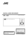
DIGITAL VIDEO RECORDER
VR – 601
INSTRUCTION MANUAL
DIGITAL VIDEO RECORDER VR-601
PLAY
STOP
PAUSE
REC
REV
FWD
DISK
OPERATE
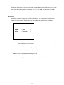
For Customer Use:
Enter below the serial No. which is
located on the rear of cabinet. Retain
this information for future reference.
Thank you for purchasing this JVC product.
Before operating this unit, please read the
instructions carefully to ensure the best
possible performance.
Model No:
VR-601
Serial No:
LST0130 - 001A
IMPORTANT SAFEGUARDS
1.
Read all of these instructions.
2.
Save these instructions for later use.
3.
All warnings on the product and in the operating instructions should be adhered to.
4.
Unplug this appliance system from the wall outlet before cleaning. Do not use liquid cleaners or aerosol cleaners. Use a
damp cloth for cleaning.
5.
Do not use attachments not recommended by the appliance manufacturer as they may cause hazards.
6.
Do not use this appliance near water “ for example, near a bathtub, washbowl, kitchen sink, or laundry tub, in a wet
basement, or near a swimming pool, etc.
7.
Do not place this appliance on an unstable cart, stand, or table. The appliance
may fall, causing serious injury to a child or adult, and serious damage to the
appliance.
Use only with a cart or stand recommended by the manufacturer, or sold with the
appliance.
Wall or shelf mounting should follow the manufacturer instructions, and should
use a mounting kit approved by the manufacturer.
An appliance and cart combination should be moved with care. Quick stops,
excessive force, and uneven surfaces may cause the appliance and cart
combination to overturn.
8.
Slots and openings in the cabinet and the back or bottom are provided for
ventilation, and to insure reliable operation of the appliance and to protect it from
overheating, these openings must not be blocked or covered. The openings should never be blocked by placing the
appliance on a bed, sofa, rug, or other similar surface. This appliance should not be placed in a built-in installation such as
a bookcase unless proper ventilation is provided.
9.
This appliance should be operated only from the type of power source indicated on the marking label. If you are not sure of
the type of power supplied to your home, consult your dealer or local power company. For appliance designed to operate
from battery power, refer to the operating instructions.
10. This appliance system is equipped with a 3-wire grounding type plug (a plug having a third (grounding) pin). This plug will
only fit into a grounding-type power outlet. This is a safety feature. If you are unable to insert the plug into the outlet,
contact your electrician to replace obsolete outlet. Do not defeat the safety purpose of the grounding plug.
11. For added protection for this product during a lightning storm, or when it is left unattended and unused for long periods of
time, unplug it from the wall outlet and disconnect the antenna or cable system. This will prevent damage to the product
due to lightning and power-line surges.
12. Do not allow anything to rest on the power cord. Do not locate this appliance where the cord will be abused by persons
walking on it.
13. Follow all warnings and instructions marked on the appliance.
14. Do not overload wall outlets and extension cords as this can result in fire or electric shock.
15. Never push objects of any kind into this appliance through cabinet slots as they may touch dangerous voltage points or
short out parts that could result in a fire or electric shock. Never spill liquid of any kind on the appliance.
16. Do not attempt to service this appliance yourself as opening or removing covers may touch dangerous voltage or other
hazards. Refer all servicing to qualified service personnel.
17. Unplug this appliance from the wall outlet and refer servicing to qualified service personnel under the following conditions:
a.
When the power cord or plug is damaged or frayed.
b.
If liquid has been spilled into the appliance.
c.
If the appliance has been exposed to rain or water.
d.
If the appliance does not operate normally by following the operating instructions. Adjust only those controls that are
covered by the operating instructions as improper adjustment of other controls may result in damage and will often
require extensive work by a qualified technician to restore the appliance to normal operation.
e.
If the appliance has been dropped or the cabinet has been damaged.
f.
When the appliance exhibits a distinct change in performance this indicates a need for service.
18. When replacement parts are required, be sure the service technician has used replacement parts specified by the
manufacturer that have the same characteristics as the original part. Unauthorized substitutions may result in fire, electric
shock, or other hazards.
19. Upon completion of any service or repairs to this appliance, ask the service technician to perform routine safety checks to
determine that the appliance is in safe operating condition.
2
SAFETY PRECAUTIONS (FOR USA AND CANADA)
The lightening flash with arrowhead symbol, within
an equilateral triangle, is intended to alert the user
to the presence of uninsulated “dangerous voltage”
within the product’s enclosure that may be of
sufficient magnitude to constitute a risk of electric
shock to persons.
Le symbole de l’ éclair a l’ interieur d’ un triangle equilateral
est destine a alerter l’ utilisateur sur la presence d’ une tension
dangereuse non isolee dans le boitier duprodult. Cette
tension est sufflsante pour provoquer l’ electrocution de
personnes
Le point d’ exclamation a l’linterieur d’ un triangle equilateral
est destine a alerter l’ utilisateur sur la presence d’ openations
d’ entretien importantes au sujet desquelles des
renseignements se trouvent dand le manuel d’ instructions.
The exclamation point within an equilateral triangle
is intended to alert the user to the presence of
important operating and maintenance (servicing)
instructions in the literature accompanying the
appliance.
Ces symbols ne sont utilizes qu’aux Etats-Unis.
WARNING:
AVERTISSEMENT:
TO REDUCE THE RISK OF FIRE OR
ELECTRIC SHOCK, DO NOT EXPOSE THIS
APPLIANCE TO RAIN OR MOISTURE.
POUR EVITER LES RISQUES D’INCENDIE
OU D’ELECTROCUTION, NE PAS EXPOSER
L’APPAREIL A L’HUMIDITE OU A LA PLUIE.
This unit should be used with 120V AC only.
CAUTION:
To prevent electric shocks and fire hazards, DO
NOT use any other power.
Ce magnetoscope ne doit etre utilize que sur du
courant alternatif en 120V.
ATTENTION:
NOTE:
Afin d’eviter tout resque d’incendie ou
d’electrocution, ne pas utiliser d’aufres sources
d’alimentation electrique.
The rating plate (serial number plate) is on the rear of the unit.
INFORMATION
REMARQUE:
This equipment has been tested and found to comply with the limits
for a Class A digital device, pursuant to Part 15 of the FCC Rules.
These limits are designed to provide reasonable protection against
harmful interference when the equipment is operated in a
commercial environment. This equipment generates, uses, and can
radiate radio frequency energy and, if not installed and used in
accordance with the instruction manual, may cause harmful
interference to radio communications.
Operation of this equipment in a residential area is likely to cause
harmful interference in which case the user will be required to
correct the interference at his own expense.
La plaque d’identification (numero de serie) se trouve dur le
pammeau arriere de l’appareil.
WARNING:
The battery used in the VR-601U must be replaced by a
JVC authorized service dealer only.
CAUTION
WARNING:
CHANGES OR MODIFICATIONS NOT APPROVED
BY JVC COULD VOID USER’S AUTHORITY TO
OPERATE THE EQUIPMENT.
The installation of this equipment should be made by a
qualified service person and should conform to all local
codes.
This Class A digital apparatus meets all
requirements of the Canadian Interference-Causing
Equipment Regulations.
Cet appareil numerique de la Classe A respecte
toutes les exigencies du Reglement sur le materiel
brouilleur du Canada.
CAUTION
Risk of explosion if replaced by an incorrect
type. Dispose of used batteries according to
the instructions.
.
3
SAFETY PRECAUTIONS (FOR EUROPE AND AUSTRALIA)
Warning Notice
FOR YOUR SAFETY (Australia)
1. Insert this plug only into effectively earthed
three-pin power outlet.
2. If any doubt exists regarding the earthing,
consult a qualified electrician.
3. Extension cord, if used, must be
three-core correctly wired.
IMPORTANT (In the United Kingdom)
Mains Supply (AC 230 V)
WARNING – THIS APPARATUS
MUST BE EARTHED
The wires in this mains lead are coloured in
accordance with the following code;
GREEN-and-YELLOW : EARTH
BLUE
: NEUTRAL
BROWN
: LIVE
As the colours of the wires in the mains lead of
this apparatus may not correspond with the
coloured markings identifying the terminals in
your plug, proceed as follows.
The wire which is coloured GREEN-AND
-YELLOW must be connected to the terminal
in the plug which is marked with the letter E or
by the safety earth symbol or coloured GREEN
or GREEN-AND-YELLOW. The wire which is
coloured BLUE must be connected to the
terminal which is marked with the letter N or
which is coloured BLOCK. The wire which is
coloured BROWN must be connected to the
terminal which is marked with the letter L or
coloured RED.
POWER SYSTEM
Connection to the mains supply
This unit operates on voltage of 220 V to 240 V
AC, 50 Hz/60Hz.
WARNING:
TO REDUCE THE RISK OF FIRE OR
ELECTRIC SHOCK, DO NOT EXPOSE THIS
APPLIANCE TO RAIN OR MOISTURE.
CAUTION
To prevent electric shock, do not open the
cabinet. No user serviceable partsinslde. Refer
servicing to qualified service personnel.
Note:
The rating plate and the safety caution are on
the rear of the unit.
The OPERATE button does not completely
shutoff mains power from the unit, but switches
operating current on and off.
WARNING
It should be noted that it may be unlawful to
rerecord pre-recorded tapes, records, or discs
without the consent of the owner of copyright
in the sound or video recording, broadcast, or
cable programme and in any literary, dramatic,
musical or artistic work embodied therein.
CAUTION
RED colour indications on the operation panel
are provided but they are not safety related.
RED colour indications:
(1) For Recording Button.
4
SAFETY PRECAUTIONS
Place of storage and use
Maintaining the unit (Please turn off the
power before performing maintenance
work.)
Please avoid storing or using this DVR in the
following places:
Extremely hot or cold places beyond the
Please wipe the unit with a soft cloth. Do not wipe
allowable temperature for operation (5°C –
it with thinner or benzene lest the surface melts or
40°C).
becomes dull. For stubborn stains, wipe first with a
Humid or dry places beyond the allowable
water-diluted neutral detergent and then wipe dry.
humidity range for operation (30% –80% RH).
Places exposed to oil, smoke or steam, such
About the provided power cables (for
VR-601 U)
as the kitchen vicinity.
Two power cables are provided with the
Intensely vibrating or unstable places.
VR-601 U. Use the one that corresponds to
Places prone to condensation.
your power – supply.
Dusty or sandy places.
Places that generate strong magnetic fields,
When usage voltage is 120V or less; use the
e.g., transformer or motor.
A – type (flat – pin type).power cable.
Places near devices that generate electric
When usage voltage is 127V or over; use the
waves, e.g., transceiver or mobile phone.
C – type (round – pin type).power cable.
Places that generate radiation, X-rays or
Please use the provided AC adapter to
connect the DVR to a power source.
corrosive gases.
Handling the unit
Please do not place heavy objects on the DVR,
Please use the supplied power cord.
Using a different type or damaged cord
may cause fire or electric shock.
like a monitor or TV.
Please
keep
the
mobile
rack
into
the
Hard-disk
compartment. As injury may result from fingers
The hard-disk is a consumable item.
getting clamped.
Replacement is recommended after 10000
Please do not block the ventilation openings.
hours of use ( if used in a 25∘C environment ).
Avoid violent shocks to the unit. Do not drop the
For information on maintenance planning and
unit.
costs, consult your nearest JVC dealer.
Please remove the AC adapter to save energy
when the unit is not in use.
To save energy, be sure to turn off the
system when not in use.
5
AC adapter section
IMPORTANT SAFETY INSTRUCTIONS
1) Read all of these instructions.
2) Keep these instructions.
3) Heed all warnings.
4) Follow all instructions.
5) Do not use this apparatus near water.
6) Clean only with dry cloth.
7) Do not block any ventilation openings. Install in accordance with the manufacturer’s instructions.
8) Do not install near any heat sources such as radiators, heat registers, stoves, or other apparatus
(including amplifiers) that produce heat.
9) Do not defeat the safety purpose of the polarized or grounding-type plug. A polarized plug has two
blades with one wider than the other. A grounding type plug has two blades and a third grounding prong.
The wide blade or the third prong are provided for your safety. If the provided plug does not fit into your
outlet, consult an electrician for replacement of the obsolete outlet.
10) Protect the power cord from being walked on or pinched particularly at plugs, convenience receptacles,
and the point where they exit from the apparatus.
11) Only use attachments/accessories specified by the manufacturer.
12) Use only with the cart, stand, tripod, bracket, or the table specified by the
manufacturer, or sold with the apparatus.
When a cart is used, use caution when moving the cart/apparatus
combination to avoid injury from tip-over.
13) Unplug this apparatus during lightning storms or when unused for long periods of time.
14) Refer all servicing to qualified service personnel. Servicing is required when the apparatus has been
damaged in any way, such as power-supply cord or plug is damaged, liquid has been spilled or objects
have fallen into the apparatus, the apparatus has been exposed to rain or moisture, does not operate
normally, or has been dropped.
WARNING - To reduce the risk of fire or electric shock, do not expose this apparatus to rain or moisture.
Apparatus shall not be exposed to dripping or splashing and no objects filled with liquids, such as vases,
shall be placed on the apparatus.
CAUTION – These servicing instructions are for use by qualified service personnel only. To reduce the
risk of electric shock, do not perform any servicing other than that contained in the operating
instructions unless you are qualified to do so.
6
Table Of Contents
1. PRODUCT FEATURES ..................................................................................................... 9
1.1 Product Introduction .................................................................................................................... 9
1.2 Product Features.......................................................................................................................... 9
2. DESCRIPTION OF THE FRONT/REAR VIEW................................................................ 10
2.1 Front View .................................................................................................................................. 10
2.2 Rear View ................................................................................................................................... 13
2.3 ALARM In/Out ........................................................................................................................... 14
3. INSTALLATION ............................................................................................................... 15
3.1 Basic Connection ....................................................................................................................... 15
3.2 Hard-Disk Drive Installation ..................................................................................................... 19
3.3 System Information .................................................................................................................... 20
3.4 Updating System Software ......................................................................................................... 21
4. BASIC OPERATIONS ..................................................................................................... 22
4.1 Configuring Recording Settings................................................................................................. 22
4.2 Recording Operations ................................................................................................................ 25
4.3 Playback Operations.................................................................................................................. 30
4.4 Search Operations...................................................................................................................... 32
4.5 Backup Operations..................................................................................................................... 36
4.6 Key Lock Operation ................................................................................................................... 39
5. MENU SETUP ................................................................................................................. 40
5.1 REC SETTING ........................................................................................................................... 41
5.2 ALARM SETTING ...................................................................................................................... 42
5.3 CLOCK / TIMER........................................................................................................................ 45
5.4 COMMUNICATION .................................................................................................................. 46
5.5 DISK SETTING .......................................................................................................................... 49
5.6 SYSTEM ..................................................................................................................................... 50
7
6. RS-232 & RS-485 PROTOCOL....................................................................................... 53
6.1 Setup........................................................................................................................................... 53
6.2 Communication Protocol:.......................................................................................................... 53
7. MOBILE RACK INSTALLATION..................................................................................... 56
8. SYSTEM DEFAULT......................................................................................................... 59
9. O.S.D MESSAGE ............................................................................................................ 61
10. NETWORK VIEWER AND IMAGE VIEWER................................................................. 62
10.1 The Network Viewer ................................................................................................................. 62
10.2 The Image Viewer..................................................................................................................... 70
11. INDEX TABLE ............................................................................................................... 71
12. NETWORK CONFIGURATION ..................................................................................... 72
12.1 Cable Connections ................................................................................................................... 72
12.2 Configure Your DVR Network Settings .................................................................................... 73
12.3 TCP/IP Communication Software............................................................................................ 75
12.4 TCP/IP installation .................................................................................................................. 77
12.5 TCP/IP Configuration setting .................................................................................................. 77
12.6 Connection Testing................................................................................................................... 78
13. SPECIFICATIONS ......................................................................................................... 80
14. COMPATIBLE MULTIPLEXERS ................................................................................... 81
8
1. PRODUCT FEATURES
1.1 Product Introduction
This DVR is a storage media of digital video image, which uses hard-disk drives instead of VCR tapes
to store video. It enables you to enjoy the extreme flexibility of digital image archiving instead of clumsy
tape management, and is compatible with most multiplexers in the market. Equipped with a range of
comprehensive features, such as playback picture-by-picture, quick access video recording by time
and event, the upgradeable software of the system, the expandable capacities of hard drive, and much
more, the DVR will make your applications far more flexible and effective than ever before. For all, the
DVR is going to prove the timely substitute for Time-lapse VCR.
1.2 Product Features
* Stores video in hard-disk drives instead of VCR tapes.
* Maximum 2 hard-disk drive capability. (One removable)
* Hard-disk drive hot-swapping capability.
* Pre-alarm image recording.
* Capable of working with various known multiplexers.
* Time-lapse and real-time recording.
* Refresh rate up to 60 IPS (50 IPS for PAL).
* Image quality selectable at 4 different levels for recording.
* Event/Timer/Alarm recording mode.
* Quick search by time, alarm, event, and recording list.
* Fast and slow playback of recorded video at various speeds.
* Single-picture playback.
* On-screen setup menu, title and system timer.
* Password protection.
* Disk-full warning and operation status LEDs.
* RS-232, RS-485 communication port.
* Remote control via RS-232, RS-485 and Ethernet ports
* Power interruption recovery.
* Operation-status record log.
* Distributing live and recorded images through TCP/IP network environment.
* Audio function included
* Built-in SD card slot for copying image to SD card
* Support DHCP protocol.
9
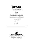
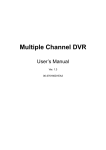
2. DESCRIPTION OF THE FRONT/REAR VIEW
2.1 Front View
1
Operate
Display
23
Setup
Search
Enter
Monitor
2
24
3
4
5
PLAY
STOP
PAUSE
REC
6
REV
FWD
DISK
OPERATE
A-rec
T-rec
7
8
9
10
11
14
13
12
15
16
17
18
19
20
21
22
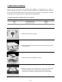
Hard-disk drive compartment.
The compartment allows you to install a hard-disk drive mostly for backup purposes. Make sure the
drive is well secured with the mounting screws in the mobile rack before you put the rack into the
compartment. And remember to turn on the power of the compartment by locking it.
Hard-disk compartment lock:
The key lock secures a hard-disk in place. Unlock the compartment before you remove the
hard-disk from the slot without turning off the device.
PAUSE button:
In a playback display, press this to freeze the display. During the freeze, press to display one
frame/field of a picture at a time in the forward direction. (Illuminate green in PAUSE mode.)
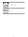
PLAY button:
Press to play back a recorded video from the hard-disk. (Illuminate green in PLAY mode.)
STOP button:
Press to stop playing back a recorded video or recording video into a hard-disk. (Illuminate green
in STOP mode.)
REC button:
Press to start recording video into a hard-disk while in the live display mode.(Illuminate red in
REC mode.)
OPERATE button:
Press this button for at least 3 seconds to power off. Press again to activate the device.
DISPLAY button:
Press to show the system operation status on the screen.
10
Setup button:
Press this to enter the setup menu. Press again to exit the setup mode.
Search button:
Press to enter the search mode to access recorded video.
Left / Right buttons:
Press the two buttons to highlight desired items in the menu setup mode. For Key Lock operation,
press these two buttons simultaneously once; to disable Key Lock, press these two buttons
simultaneously again.
Up / Down buttons:
Press these two buttons to select the desired contents for programming in the setup menu mode.
Enter Button:
Press to enter a selected item and save the setting in the menu setup mode.
Monitor button:
Press to switch between a multiplexer-decoded video and the encoded video to be displayed
when connected with a multiplexer. When the button light is on it indicates the unit is displaying
the decoded video.( The images are not multiplexing . ) In this mode, the unit doesn’t display the
OSD message of the unit on the screen. However, this doesn’t affect the unit’s OSD message
which is recorded into hard-disk drives. When the button light is off it indicates the unit is
displaying encoded video. (The images switch swiftly).
T-rec Indicator:
This indicator of the timer recording mode lights up to signal the scheduled record setting is on.
A-rec Indicator:
This indicator of the alarm recording mode lights up to indicate the alarm record setting is on.
DISK Indicator:
The indicator shows the operation status of the unit’s hard-disk drives. The green light indicates
the hard-disk drive is storing or retrieving data. The red light signals the hard-disk drive is filling up.
The orange light indicates the hard-disk is retrieving data at disk-full status.
Shuttle Ring:
The shuttle can be moved forward and backward for playback in either direction. Turn this left to
play a recorded video in the reverse direction at faster or slower speeds than the recorded speed.
Turn this right to play a recorded video in the forward direction at faster or slower speeds than the
recorded speed.
Jog Dial:
This dial can act in both a forward and a backward direction, as well as step by step. Turn this left
to play a recorded video in the reverse direction. Turn this right to play a recorded video in the
forward direction.
OPERATE Indicator:
Indicates the power status of the unit. The green light indicates the hard-disk drive is activating.
The orange light signals the hard-disk drive is power stand by.
11
Mobile Rack Power LED:
Indicates the power status of the Mobile Rack. The green light indicates the Mobile Rack is
activating.
Mobile Rack HDD LED:
Indicates the HDD status of the Mobile Rack. The orange light indicates the HDD is storing or
retrieving data.
12
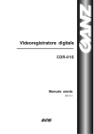
2.2 Rear View
25 26 27
28
29 30 31
SD Card
FROM MUX
MAIN MONITOR
VIDEO
AUDIO
RS-485
IN
IN
32
RS-232
OUT
OUT
TO
MUX'S VCR IN
ETHERNET
10/100
TO
MONITOR
ALARM
33 34
I/O
35
DC12V
37 38 36
VIDEO IN Connector: This BNC connector is used to connect the video output from a camera or a
MUX to the DVR.
FROM MUX MAIN MONITOR Connector: This BNC connector is used to connect the live video output
from a MUX to the DVR.
AUDIO IN Connector: This connector is used to connect the audio output from a camera, a MUX or
other devices to the DVR.
ETHERNET 10/100 Connector: This is one standard RJ-45 connector for 10/100 Mbps Ethernet
networks.
RS-485 Port: The RS-485 communication ports function as connectors when two or more units are
serially connected to expand the storage capacity.
SD CARD Slot: This is used for system software updating and archiving/accessing critical images.
RS-232 Port: The RS-232 communication port functions as a connector to an external control device.
Please refer to RS-232 & RS-485 Protocol for more details.
VIDEO OUT Connector: The connector provides the unit’s composite video signals to a MUX.
MONITOR Connector: The connector provides the unit’s composite video or a MUX’s live signal if
connected to a display device.
AUDIO OUT: This provides the unit’s audio signal to a speaker.
ALARM I/O: This is a 9-PIN D-SUB connector including SWITCH OUT, GROUND, ALARM OUT, DISK
FULL, RECORD IN, ALARM RESET, and ALARM IN for connecting with external devices. Please
refer to the next section for details.
Plug Inlet: The inlet connects to an external power supply. Connect to the provided AC adapter.
Wire Catch: The wire catch secures the power cord and keeps it in place (so that it does not droop or
hang loosely).
Ground Screw’s: The ground screw is for chassis terminal.
13
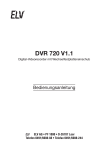
2.3 ALARM In/Out
DISK FULL
ALARM RESET
ALARM OUT
RECORD IN
GROUND
5
4
9
3
8
2
7
1
6
ALARM IN
SWITCH OUT
NO CONNECTION
NO CONNECTION
*THIS FIGURE IS LOOKED FROM THE REAR
1.
GND: Ground Contact.
2.
ALARM OUT (OUTPUT): This is an alarm output trigger. Connect this to external devices such
as buzzers or lights. (
3.
5V
0V(Active)
)
5V
0V(Active)
)
RECORD IN (INPUT): This pin connects to a record trigger device for starting a record.
(
6.
)
ALARM RESET (INPUT): This pin connects to an alarm-clear device for clearing an alarm.
(
5.
0V(Active)
DISK FULL (OUTPUT): This is a disk full output trigger. Connect this to external devices such
as buzzers or lights. (
4.
5V
5V
0V(Active)
)
SWITCH OUT (OUTPUT): This pin, sending out timing signals (falling / negative) to a
multiplexer, connects to a multiplexer’s trigger terminal so the multiplexer can switch to use the
same recording speed as the DVR.
7.
NO CONNECTION
8.
NO CONNECTION
9.
ALARM IN (INPUT): This is an alarm input which can be programmed in the menu system to
5V
Normally Open or Normally Closed. (
0V(Active)
14
)
3. INSTALLATION
Please follow the instructions and the diagram below to set up the system.
3.1 Basic Connection
CONNECTIONG TO THE AC ADAPTER
Connect the provided AC adapter to the main unit.
Screw
SD Card
VIDEO
Clamp
FROM MUX
MAIN MONITOR
AUDIO
IN
RS-485
IN
ETHERNET
10/100
RS-232
OUT
OUT
TO
MUX'S VCR IN
TO
MONITOR
ALARM
I/O
DC12V
DC IN terminal
AC
DC cord
Provided AC
mains cable
Provided AC adapter
(model:STD-1205)
1. Connect the DC cord of the AC adapter to the DC IN terminal of the main unit.
2. To prevent accidental disconnection of the DC cord, fasten the DC cord with a wire catch.
1) Remove 1 screw followed by the wire catch.
2) Insert the DC cord into the wire catch and fasten the wire catch unto the main unit.
3. Connect the provided power cord to the AC IN terminal of the AC adapter.
4. Connect the power cord to the power socket.
• Power is channeled into the unit and the OPERATE indicator lights up green.
(OPERATE ON mode)
• Press OPERATE button
for at least 3 seconds to power off and the OPERATE indicator lights
up orange.. (OPERATE OFF mode)
The orange light signals the hard-disk drive is power stand by.
Memo
• Even in the OPERATE OFF mode, a small amount of electricity will still flow into the unit.
• When the unit is in the OPERATE OFF mode, no operation can be performed except that of the
OPERATE button.
Note:
• Please supply power to the unit via the provided AC adapter. Do not use other power sources.
• During recording or playback, please do not unplug the DC or power cord.
* About the location of the buttons, please refer to Page 10 2.1 Front View.
15
CONNECTING WITH A SINGLE CAMERA
Please set the MULTIPLEXER option to OFF on the REC SETTING page in the setup menu
when it is connected with a single camera. (Please refer to section 5.1 MULTIPLEXER option)
Camera
SD Card
FROM MUX
MAIN MONITOR
VIDEO
AUDIO
IN
RS-485
IN
ETHERNET
10/100
OUT
OUT
TO
MUX'S VCR IN
RS-232
TO
MONITOR
ALARM
I/O
DC12V
Monitor
CONNECTING WITH A MULTIPLEXER
To match the multiplexer’s recording speed, please set the MULTIPLEXER option to ON on the
REC SETTING page in the setup menu when it is connected with a multiplexer. (Please refer to
section 5.1 MULTIPLEXER option)
Caution: When being set up so that an multiplexer may record only the Alarm-in camera
during alarm record, or when there is only one camera input, if it is going to see
the playback picture of VR-601 with the monitor out of multiplexer, the picture
may not update. Before beginning record for the multiplexer in the case of usage,
the playback picture can update normally by setting REC RATE to 60F/S.
16
CONNECTING WITH A QUAD
Please set the MULTIPLEXER option to OFF on the REC SETTING page in the setup menu
when it is connected with a quad. (Please refer to section 5.1 MULTIPLEXER option)
Multiplexer
IN
Audio
OUT
Trig In
PC
S-video
SD Card
FROM MUX
MAIN MONITOR
VIDEO
AUDIO
IN
RS-485
IN
ETHERNET
10/100
RS-232
OUT
OUT
TO
MUX'S VCR IN
TO
MONITOR
ALARM
Monitor
I/O
DC12V
Speaker
5
GROUND
SWITCH OUT
4
9
3
8
2
7
1
6
Quad
IN
Audio
OUT
PC
S-video
SD Card
FROM MUX
MAIN MONITOR
VIDEO
AUDIO
IN
RS-485
IN
ETHERNET
10/100
RS-232
OUT
OUT
TO
MUX'S VCR IN
TO
MONITOR
ALARM
Monitor
Speaker
17
I/O
DC12V
ATTACHING AN EXTERNAL DEVICE TO DVR
Connect an alarm out, alarm input, and a peripheral device as shown in the diagram below.
Lamp
SD Card
VIDEO
FROM MUX
MAIN MONITOR
AUDIO
IN
RS-485
IN
ETHERNET
10/100
RS-232
OUT
OUT
TO
MUX'S VCR IN
TO
MONITOR
ALARM
I/O
DC12V
Alarm Reset
(Normally Open)
5
Ground
4
9
3
8
2
7
1
6
Alarm in
(Normally Open)
CLOCK SET
Please set the clock before operating the DVR. (For operation details, please refer to section 5.3
CLOCK/TIMER)
18
3.2 Hard-Disk Drive Installation
The DVR is equipped with two compartments of hard-disk drive. The unit usually comes with one
hard-disk drive installed in the compartment HD1, which is default-configured as a master. If you need
a second hard-disk drive to be installed in the compartment HD2 (Mobile), please contact your
distributors or installers for specific instructions on how to install it. Please don’t serve yourself before
consulting your installers. If there is only one hard-disk drive in the mobile compartment, please set the
HD2 USAGE option to REC (Please refer to section 5.5) before proceed recording function. The
jumper-settings arrangement of installed hard-disk drives for the system (Table 3.2 A.) is shown in the
tables below.
Table 3.2 A. The jumper settings of hard-disk drives in the system
Location
Jumper
IDE 1
Compartment HD 1
Master (Default)
IDE 2
Compartment HD 2
Master
Table 3.2 B. Compatible hard-disk drives
Manufacturer
Seagate
Maxtor
Model
Capacity
Rotation
ST380020A/P
80GB
5400 RPM
ST340810A/P
40GB
5400 RPM
4A160J0-1A
160GB
5400 RPM
4R080L0-1
80GB
5400 RPM
6Y120L0-1
120GB
7200 RPM
NOTE: Hard-disk drives not shown on this list have not been tested by the engineering team
and are not recommended for use with this product. For the latest updated list on the
recommended hard-disk drives, please contact your dealers or distributors.
19
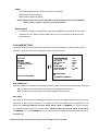
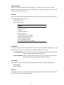
3.3 System Information
You can display system settings information as shown on Table 3.3 A below at any time by pressing
. In the playback mode, the recorded video information is displayed. In the live or
the Display button
recording mode, the Manual Recording information is displayed. However, when the DVR is displaying
a decoded image from a multiplexer, you must first switch the unit to encoded image displaying (The
pictures is switching swiftly and the light of Monitor button
. Each sequential press of the Display button
is off) by pressing the Monitor button
displays a different message detailed in the
following example. By default, the unit displays time, date, and an indicating bar of capacity status on a
monitor as shown next.
The TOP
of the HDD
Default display
(Capacity Used)
(Capacity Remaining)
09-05-2003
(Date)
Current
Position
The END
of the HDD
16:13:02
(System Time)
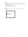
Press the Display button
once; the DVR will display the following sample message plus the default
display. Press the Display button
again; the unit will not display any OSD message. Press the
button one more time to back to the default display.
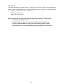
Table 3.3 A.
Description of Table 3.3 A
1+ 2: 59G
12.4 HR
QUALITY: BEST
NTSC
RATE: 6 HR
20 F/S
MUX : OFF
9K
(1+2: 59G): Total capacity of installed hard-disk, 59 GB
(12.4 HR): Total 12.4 hour recording time available
(
): Timer record activated
(
): Alarm record activated
(QUALITY: BEST): Record quality setting, BEST
(NTSC): NTSC system
(RATE: 6 HR): Setting of Record time mode, 6 hours
HD P
SIZE
POS
1
Y
20 G
39.5% P
2
Y
39 G
0.0% R
IP : 192 . 168 . 1 . 90
(20 F/S): Record speed setting, 20 fields/sec
(MUX: OFF): Only connected to a single camera.
(
(
): Audio function activated
): Indicate which HDD is activated
(9K): The image file size
(HD): Hard-disk Compartment
(P): Y Hard-disk installed; .
No hard-disk installed
(SIZE 20G): The capacity of the installed hard-disk
(POS): Percentage of system; R: Recording; P: Playback
(IP : 192 . 168 . 1 . 90): Setting of the Ethernet
communication,192.168.1.90
( ): External signal
(
X): Cannot operate at now
* About the location of the buttons, please refer to Page 10 2.1 Front View.
20
3.4 Updating System Software
If the system software of the DVR needs to be upgraded, please contact your JVC dealer.
21
4. BASIC OPERATIONS
This section shows you how to operate and manage the DVR when it gets in the way.
4.1 Configuring Recording Settings
Recording Time settings (Recording Rate and Picture Quality Setting)
Recording time will vary depending on the image size, recording rate, and the capacity of the hard-disk
drives. Generally, the DVR comes with a built-in hard-disk drive for continuous recording from one to
four weeks under most recording conditions. The table below shows the possible recording times based
on a 80GB hard-disk drive at certain refresh rates and the corresponding image quality. With one or
more hard-disk drive(s) in operation, please calculate the recording time using the table below in
accordance with your requirement. For a NTSC unit, for example, if the unit is set to record images with
BEST quality at a 60 fps record rate, normally a 80GB hard-disk drive will be filled in 15 hours (See the
gray area in the table). If the total capacity of 240GB hard-disk drives is in use under the same refresh
rate and picture quality, it will be filled in 45 hours (3 times the rate of a 80GB hard-disk drive).
Set up the REC Time Mode when a multiplexer is connected
If a multiplexer is connected, for optimum image recording and playback, the record speed of the
multiplexer must be correctly adjusted to match the DVR and set the MULTIPLEXER option on the
setup menu to ON. This can be done by either of methods detailed below.
Connect the SW. OUT terminal in 9-PIN D-SUB connector on the rear panel of the DVR to the
multiplexer’s trigger contact. The DVR will provide the timing signal (Negative/Falling) to the multiplexer.
Thus, if the DVR changes the recording speed, the multiplexer will automatically adjust the record to
match. A 2-hour and 4-hour timing signal in NTSC or a 3-hour and 6-hour one in PAL is constantly
negative/falling.
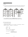
NTSC (MUX ON)
Audio ON
BEST
HIGH
STANDARD
BASIC
Refresh Rate (Field/Sec)
REC Time Mode
Possible Recording Time HDD=80GB ( hour )
44.4
95.8 208.5 380.6 598.5
55.3 118.8 255.7 459.6 708.9
73.2 156.1 330.5 580.0 869.5
108.4 227.6 467.3 785.9 1124.0
Image
Quality
60
30
20
12
5.5
2.4
1.22
0.71
1/4
1/6
1/8
2 hr
4 hr
6 hr
12 hr
24 hr
48 hr
96 hr
168 hr
480 hr
720 hr
960 hr
22
NTSC (MUX ON)
Audio OFF
BEST
Image
HIGH
Quality
STANDARD
BASIC
Refresh Rate (Field/Sec)
REC Time Mode
15.0
18.0
22.5
30.1
18.0
22.5
30.1
45.1
BEST
HIGH
STANDARD
BASIC
Refresh Rate (Field/Sec)
REC Time Mode
30
20
12
5.5
2.4
1.22
0.71
1/4
1/6
1/8
4 hr
6 hr
12 hr
24 hr
48 hr
96 hr
168 hr
480 hr
720 hr
960 hr
Possible Recording Time HDD=80GB ( hour )
53.1 104.2 216.2 387.2 603.9
66.1 129.0 264.9 467.3 715.1
87.4 169.4 342.1 589.3 876.4
129.0 246.4 482.7 797.3 1131.7
60
30
**20
**12
**5.5
2.4
1.22
0.71
1/4
1/6
1/8
2 hr
4 hr
6 hr
12 hr
24 hr
48 hr
96 hr
168 hr
480 hr
720 hr
960 hr
18.0
22.5
30.1
45.1
Possible Recording Time HDD=80GB ( hour )
36.1
54.2 108.4 234.9 451.8 777.1 2186.7
45.1
67.7 135.5 293.6 564.7 971.3 2733.4
60.2
90.3 180.7 391.5 753.0 1295.1 3644.6
90.3 135.5 271.0 587.3 1129.5 1942.7 5466.9
3271.1
4088.9
5451.8
8177.8
4355.4
5444.3
7259.1
10888.6
15.0
18.0
22.5
30.1
60
30
**20
**12
**5.5
2.4
1.22
0.71
1/4
1/6
1/8
2 hr
4 hr
6 hr
12 hr
24 hr
48 hr
96 hr
168 hr
480 hr
720 hr
960 hr
PAL (MUX ON)
Audio ON
BEST
HIGH
STANDARD
BASIC
Refresh Rate (Field/Sec)
REC Time Mode
Possible Recording Time HDD=80GB ( hour )
44.4
78.9 145.3 268.6 432.8
55.8
98.9 181.0 330.7 524.6
75.3 132.5 240.0 430.0 666.0
109.5 190.9 339.4 589.5 879.2
Image
Quality
50
25
17
10
5.5
2.9
1.52
0.88
1/4
1/6
1/8
3 hr
6 hr
9 hr
12 hr
24 hr
48 hr
96 hr
168 hr
480 hr
720 hr
960 hr
18.0
22.8
30.9
45.6
Possible Recording Time HDD=80GB ( hour )
27.1
45.1
81.3 153.6 298.1 515.0 1816.2
34.2
57.0 102.7 194.0 376.6 650.6 2294.2
46.4
77.4 139.4 263.3 511.1 882.9 3113.6
68.4 114.1 205.4 388.0 753.3 1301.2 4588.5
2719.9
3435.6
4662.7
6871.3
3623.5
4577.1
6211.7
9154.2
PAL (MUX ON)
Audio OFF
BEST
HIGH
STANDARD
BASIC
Refresh Rate (Field/Sec)
REC Time Mode
Image
Quality
4346.4
5433.0
7244.0
10866.1
60
NTSC (MUX OFF)
Audio OFF
Image
Quality
3262.0
4077.6
5436.8
8155.2
2 hr
NTSC (MUX OFF)
Audio ON
BEST
Image
HIGH
Quality
STANDARD
BASIC
Refresh Rate (Field/Sec)
REC Time Mode
Possible Recording Time HDD=80GB ( hour )
27.1
45.1
99.3 225.9 442.7 768.0 2177.7
33.8
56.4 124.2 282.3 553.4 960.1 2722.1
45.1
75.3 165.6 376.5 737.9 1280.1 3629.5
67.7 112.9 248.4 564.7 1106.9 1920.2 5444.3
15.4
18.0
22.8
30.9
50
25
17
10
5.5
2.9
1.52
0.88
1/4
1/6
1/8
3 hr
6 hr
9 hr
12 hr
24 hr
48 hr
96 hr
168 hr
480 hr
720 hr
960 hr
23
PAL (MUX OFF)
Audio ON
BEST
HIGH
STANDARD
BASIC
Refresh Rate (Field/Sec)
REC Time Mode
Possible Recording Time HDD=80GB ( hour )
53.1
87.4 153.4 275.9 439.1
66.7 109.5 190.9 339.4 532.0
89.8 146.5 252.8 441.0 674.8
130.3 210.5 356.8 603.4 889.5
Image
Quality
50
25
**17
**10
**5.5
2.9
1.52
0.88
1/4
1/6
1/8
3 hr
6 hr
9 hr
12 hr
24 hr
48 hr
96 hr
168 hr
480 hr
720 hr
960 hr
18.0
22.8
30.9
45.6
Possible Recording Time HDD=80GB ( hour )
36.1
54.2
90.3 162.6 307.2 524.1 1825.3
45.6
68.4 114.1 205.4 388.0 662.0 2305.6
61.9
92.9 154.9 278.8 526.6 898.4 3129.1
91.3 136.9 228.2 410.9 776.1 1324.0 4611.3
2728.9
3447.0
4678.2
6894.1
3632.5
4588.5
6227.2
9177.0
PAL (MUX OFF)
Audio OFF
BEST
Image
HIGH
Quality
STANDARD
BASIC
Refresh Rate (Field/Sec)
REC Time Mode
15.4
18.0
22.8
30.9
50
25
**17
**10
**5.5
2.9
1.52
0.88
1/4
1/6
1/8
3 hr
6 hr
9 hr
12 hr
24 hr
48 hr
96 hr
168 hr
480 hr
720 hr
960 hr
NOTE: Recording times on the tables above are estimated. For actual available recording
time of a recording configuration, please refer to the system information of the
DVR. (Please refer to section 3.3 system information for more details.)
NOTE: No audio function at the refresh rate in NTSC: 60 fields/sec ~ 20 fields/sec, 1/4
fields/sec ~ 1/8 fields/sec.
No audio function at the refresh rate in PAL: 50 fields/sec ~ 17 fields/sec, 1/4
fields/sec ~ 1/8 fields/sec.
NOTE: An actual recording fields number could be less than the Refresh Rate on the table
above.
** : For NTSC and Mux Off Mode, recording rate 20F/S would be actually 15 F/S, 12F/S
would be actually 10 F/S, 5.5 F/S would be actually 5F/S.
For PAL and Mux Off Mode, recording rate 17F/S would be actually 12.5 F/S, 10F/S
would be actually 8.3 F/S, 5.5 F/S would be actually 5F/S.
( This adjustment is to avoid image shaking during playback at the same speed )
24
4.2 Recording Operations
This section details the way to record video into hard-disk drives. Before commencing with the recording
function, please configure the recording setting properly according to your needs.
4.2.1 Manual Recording
When the DVR is in live display mode, take the following steps to start recording:
to record video into a hard-disk drive with the
(1) In live display, press the REC button
corresponding programmed recording settings. The monitor should display a flashing REC
message and the REC button
(2) Press the STOP button
will light up indicating the DVR is in the recording status.
to stop recording any time.
(3) To access just recorded video, please refer to section 4.4 for more details.
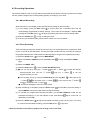
4.2.2 Timer Recording
Timer recording provides two periods of time each day in a weekly table which programs the DVR
to turn on and off at specified times. This way the DVR will start and stop recording according to
the programmed schedule. Please take the following steps to program the scheduled recording.
(1) Press the Setup button
to enter the MAIN MENU.
(2) Select the CLOCK / TIMER and press the Enter button
to enter the CLOCK / TIMER
page.
(3) Select the TIMER-SET.
(4) Press the Enter button
to enter the REC SCHEDULE table.
(5) ● You can set up by using the “<” button
and the “>” button
day/hour/minute and use the “^” button
to locate the specific
and the “v” button
to set the
day/hour/minute you wish.
● You can also set up by using the Shuttle Ring and the Jog Dial.
“<” button
and
,
is the equal of the “>” button
is the equal of the “v” button
,
is the equal of the
is the equal of the “^” button
.
● The time is displayed in a 24-hour clock format.
(6) After scheduling is completed, press the Enter button
and set OK to save the setting or
select CANCEL to leave the page without saving the settings.
(7) To activate the programmed recording schedule, set the REC ENABLE to ON. As the
scheduled recording is on, the red indicator of the Timer Record
will be on as well. To
deactivate it, set to OFF.
(8) Press the STOP button
during the scheduled recording to stop it at any time. If you wish
to continue the scheduled recording, press the REC button
to proceed.
* About the location of the buttons, please refer to Page 10 2.1 Front View.
25
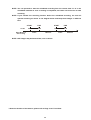
NOTE: You can proceed to start the scheduled recording from the current time if it is in the
scheduled interlude as soon as setting is completed, and come out from menu to start
recording.
NOTE: If you activate the recording function before the scheduled recording, the unit will
operate recording as shown in the diagram below and keep those Images in different
files.
03:00
Start Manual
Recording
START
END
START
06:00
08:00
12:00
Timer
Manual
Timer
NOTE: LIVE images may be freezed. But, it isn't a failure.
* About the location of the buttons, please refer to Page 10 2.1 Front View.
26
END
14:00
Manual
MAIN MENU
MAIN MENU
RECORD
ALARM
CLOCK / TIMER
COMMUNICATION
DISK
SYSTEM
RECORD
ALARM
CLOCK / TIMER
COMMUNICATION
DISK
SYSTEM
GOTO CLOCK / TIMER PAGE
GOTO CLOCK / TIMER PAGE
CLOCK / TIMER
CLOCK
REC ENABLE
TIMER
CLOCK / TIMER
: SET
: OFF
: SET
CLOCK
REC ENABLE
TIMER
MAIN PAGE
MAIN PAGE
SET REC SCHEDULE
TIMER REC ENABLE
REC SCHEDULE
START END
S : 00:00-00:00
M: 00:00-00:00
T : 00:00-00:00
W: 00:00-00:00
T : 00:00-00:00
F : 00:00-00:00
S : 00:00-00:00
START END
00:00-00:00
00:00-00:00
00:00-00:00
00:00-00:00
00:00-00:00
00:00-00:00
00:00-00:00
OK
CANCEL
TO MOVE
TO CHANGE
27
: SET
: OFF
: SET
4.2.3 Alarm Recording
Take the following steps to activate the programmed alarm recording. For ALM OPERATION,
REC RATE, REC QUALITY, AUDIO, ALM TYPE, ALM DURATION, and PRE-ALARM settings,
please refer to section 5.2 for more details.
(1) Press the Setup button
to enter the MAIN MENU.
(2) Select ALARM and press the Enter button
to enter the ALARM SETTING.
(3) Set the desired REC RATE, REC QUALITY, ALM TYPE, and ALM DURATION for use. If
audio is required, set AUDIO to ON. If pre-alarm recording is required, set PRE-ALARM to
ON.
(4) To activate the alarm recording, set ALM OPERATION to ON. To deactivate it, set ALM
OPERATION to OFF.
MAIN MENU
ALARM SETTING
RECORD
ALARM
CLOCK / TIMER
COMMUNICATION
DISK
SYSTEM
ALM OPERATION
REC RATE
REC QUALITY
AUDIO
ALM TYPE
ALM DURATION
PRE- ALARM
: OFF
: 20F/S
: BEST
: OFF
: NO
: 0 SEC
: OFF
MAIN PAGE
GOTO ALARM PAGE
ALARM REC ENABLE
4.2.4 Externally triggered Recording
By connecting the RECORD IN of ALARM I/O on the rear panel of the DVR, you can
activate/deactivate the recording function of a DVR. The file will be kept with a prefixed “R”.
Please refer to section 2.3 for more details.
* About the location of the buttons, please refer to Page 10 2.1 Front View.
28
NOTE: The status of recording operations when an alarm takes place are shown in the
diagrams below.
1
Manual or Externally
Triggered Recording
Alarm Takes Place
Actual Recording
Speed
2
Normal
Alarm
Normal
Normal
Alarm
Normal
Timer Recording
Alarm Takes Place
Actual Recording
Speed
3
Timer Recording
Alarm Takes Place
Actual Recording
Speed
4
Normal
Alarm
Timer Recording
Alarm Takes Place
Actual Recording
Speed
Alarm
Normal
29
4.3 Playback Operations
This section shows you how to operate the fast, slow, and single-picture playback functions, and
details how the unit is to playback a file in a different operation status. Please refer to the following
paragraphs specifying the relevant details. When playing a file, the monitor should display a flashing
PLAY message and the PLAY button
will light up indicating that the DVR is in the playback status.
Operation Status
A. From REC mode to Playback mode
(In live mode, directly press the PLAY button
to play a latest recorded video)
REC→〔STOP〕→〔PLAY〕……………………………… Play the latest recorded file
〔Play to the end of the file〕…Show the ending message (use search functions
or rewind to replay the file if required)
〔STOP〕→〔PLAY〕…………Play the file from the stop position
B. Search to play back a particular recorded video
Search→〔PLAY〕………………………………………… Play a selected file
〔Play to the end of the file〕…………Show the ending message (Search again or rewind
to replay the file if required)
〔STOP〕→〔PLAY〕…………………Play the file from the stop position
C. Playback from the TOP of the HDD
〔Stop: Press the “STOP” button for three seconds〕→〔PLAY〕..Playback from the TOP of the HDD
4.3.1 Fast Forward/Reverse
There are 7 speeds available for playback: 1x, 2x, 4x, 8x, 16x, 30x and 100x
While playing back recorded video at recorded speed:
Forward: Turn the Shuttle dial
to the right to view the recorded video in the forward direction at a
speed faster than the recorded speed. Each subsequent turn of the shuttle to the right
increases the forward rate, as 2x, 4x, 8x, 16x, 30x and 100x.
Reverse: Turn the Shuttle dial
to the left to view the recorded video in the reverse direction at a
speed faster than the recorded speed. Each subsequent turn of the shuttle to the left
increases the reverse rate, as -1x, -2x, -4x, -8x, -16x, -30x and -100x.
Normal: Release the Shuttle dial
to return to the normal speed of playback.
* You can also operate by using “<” button
and “>” button
.
* About the location of the buttons, please refer to Page 10 2.1 Front View.
30
NOTE: When Normal playing a recorded video from a multiplexer at 60 F/S~30F/S
(50F/S~25F/S for PAL), the playback speed is half at recorded speed
NOTE: The playback speed will be displayed on the screen. However, when playing a recorded
video from a multiplexer, the playback speed will only display in encoding
(multiplexing) the mode. Press the Monitor button
to switch between decoding and
encoding modes.
4.3.2 Slow Forward/Reverse
There are 4 speeds available for a slow playback: 1/2, 1/4, 1/8, 1/16.
While playing back recorded video at the recorded speed:
(1) Press the PAUSE button
for the slow playback mode.
(2) Forward: Turn the Shuttle dial
to the right to view the recorded video in the forward
direction at a speed slower than the recorded speed. Each subsequent turn of the
shuttle to the right increases the forward rate, as 1/2, 1/4, 1/8, and 1/16.
(3) Reverse: Turn the Shuttle dial
to the left to view the recorded video in the reverse
direction at a speed slower than the recorded speed. Each subsequent turn of the
shuttle to the left increases the reverse rate, as -1/2, -1/4, -1/8, and -1/16.
(4) Normal: Release the Shuttle dial
and then press the PLAY button
to return to the
normal speed of playback.
* You can also operate by using “<” button
and “>” button
.
4.3.3 Play Back Picture-by-picture
While playing back recorded video at the recorded speed:
for the picture-by-picture mode.
(1) Press the PAUSE button
(2) There are two ways, by PAUSE button or by JOG, available to play in the picture-by-picture
mode, but the PAUSE button
can only function in a forward direction; the other, JOG dial
, can act in both a forward and a backward direction, as well as picture-by-picture.
By PAUSE button
:
Press the PAUSE button
to display one frame/field of a picture at a time in the forward
direction. (When playing back video recorded by a multiplexer, each sequential press of
the PAUSE button
By JOG dial
will display each camera in sequence.)
:
Turn the JOG dial
clockwise to display one frame/field of a picture at a time in the forward
direction. Turn the JOG dial
counterclockwise to display one frame/field of a picture at a
time in the backward direction.
(3) Press the PLAY button
to return to the normal speed of playback.
* About the location of the buttons, please refer to Page 10 2.1 Front View.
31
4.3.4 Play Back Recorded Video from a HDD of the mobile rack
To play back a recorded video from a HD2, take the following steps:
(1) Press the Setup button
to enter the setup menu.
(2) Select DISK and press the Enter button
to enter the DISK SETTING page.
(3) Set the HD2 USAGE to REC and then exit the setup menu.
(4) Use the search function to access desired recorded video. For specific operation details
please refer to the next section 4.4 (Search Operations).
4.4 Search Operations
This section shows you how to access recorded video.
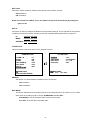
4.4.1 Full List Search
Take the following steps to proceed with the full-list search function.
(1) Press the Search button
to enter the search mode.
(2) Select the FULL LIST and press the Enter button
to access the complete list of recorded
video.
(3) Highlight the specific recorded video of your requirement and press the Enter button
to
display the selected video.
(Key Operation: Press the
and
“^” and
“v” buttons, to select a video; press the
“>” buttons, to flip over a page.)
SEARCH
A
FULL LIST
ALARM LIST
TIME SEARCH
THUMBNAIL
SD CARD
R
T
HD 1
1 11-11-02
2 11-18-02
3 12-02-03
4 01-02-03
5 02-14-03
6 02-17-03
7 02-20-03
8 02-27-03
12:20:23
13:30:16
14:20:25
17:20:46
16:11:55
13:30:22
18:33:54
19:21:12
NOTE: T: Timer recording; R: External trigger recording; A: Alarm recording.
NOTE: The maximum number of lists, for a respective HDD, is 3000.
* About the location of the buttons, please refer to Page 10 2.1 Front View.
32
10.1M
2.34M
2.05M
5.32M
24. 2M
36. 6M
6.41M
92. 3M
“<”
4.4.2 Alarm list Search
Take the following steps to proceed with the alarm-list search function.
(1) Press the Search button
to enter the search mode.
(2) Select the ALARM LIST and press the Enter button
to access the complete list of
alarm-event recorded video.
(3) Highlight the specific recorded video of your requirement and press the Enter button
to
display the selected video.
(Key Operation: Press the
and
“^” and
“v” buttons, to select a video; press the
“<”
“>” buttons, to flip over a page.)
HD 1
SEARCH
A
A
A
FULL LIST
ALARM LIST
TIME SEARCH
THUMBNAIL
SD CARD
1 11-18-02 13:22:16 16. 3M
2 02-14-03 16:55:45 15. 6M
3 02-17-03 13:22:38 17. 8M
4.4.3 TIME Search
Take the following steps to proceed with the time search function.
(1) Press the Search button
to enter the search mode.
(2) Select the TIME SEARCH and press the Enter button
to access the time-setting page.
(3) Set the time period you wish to search for the recorded video.
(4) Press the Enter button
to start searching and displaying the concerned image.
(5) If no video is found, please return to the time-setting page and repeat steps (3) and (4) again
for another search.
TIME SEARCH
SEARCH
MM DD YEAR HH
MM
11 / 17 / 2002 00 : 00
FULL LIST
ALARM LIST
TIME SEARCH
THUMBNAIL
SD CARD
* About the location of the buttons, please refer to Page 10 2.1 Front View.
33
4.4.4 THUMBNAIL Search
Take the following steps to proceed with the thumbnail search function.
(1) Press the Search button
to enter the search mode.
(2) Select the THUMBNAIL and press the Enter button
to access the thumbnail page.
(3) Set the date you wish to search for the recorded video.
(4) Press the Enter button
to start searching and displaying the concerned image.
● You can set up by using the “<” button
, the “^” button
, the “>” button
and the
to move eye focus.
“v” button
● You can also set up by using the Shuttle Ring and the Jog Dial to move eye focus.
is the equal of the “<” button
the “^” button
and
,
is the equal of the “>” button
is the equal of the “v” button
,
is the equal of
.
(5) There are 5 levels of recording range modes to choose from: 1 Hour, 10 Minutes, 1 Minute,
10 Seconds and 1 Second. Select the specific field of your requirement and press the Enter
button
to enter the next level. If you want to return the previous level, please press the
Setup button
(6) Once reaching the critical point at any level, the user can start playback by just clicking the
PLAY button
.
THUMBNAIL
SEARCH
MM DD YEAR
03 / 13 / 2003
FULL LIST
ALARM LIST
TIME SEARCH
THUMBNAIL
SD CARD
* About the location of the buttons, please refer to Page 10 2.1 Front View.
34
4.4.5 SD CARD Search
Take the following steps to proceed with the SD card search function.
(1) Insert a SD Card into the SD card slot of the rear unit.
(2) Press the Search button
to enter the search mode.
(3) Select the SD CARD and press the Enter button
to access the complete list of JPG files.
(4) Highlight the specific JPG file of your requirement and press the Enter button
to display
the image.
(5) If you need another, please return to the SD card JPG file list page and repeat steps (3) and
(4) again for another search.
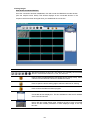
SD CARD JPG FILE
SEARCH
F0000.JPG
F0001.JPG
F0002.JPG
F0003.JPG
F0004.JPG
F0005.JPG
FULL LIST
ALARM LIST
TIME SEARCH
THUMBNAIL
SD CARD
NOTE: If you would like to delete JPG file in the SD card, please return to SD CARD JPG FILE
list page and highlight the specific JPG file of your requirement and press the Setup
button
and then select the “Yes” to delete the image.
* About the location of the buttons, please refer to Page 10 2.1 Front View.
35
4.5 Backup Operations
4.5.1 Mobile Rack HD Backup
There are three ways available to duplicate the recorded video from HD 1 (Fixed HD) to HD 2
(Mobile Rack HD). Please take the following steps to proceed.
(1) Set HD 2 to BACKUP first. Take the following steps.
Press the Setup button
to enter the setup mode and select the DISK.
Highlight DISK and press the Enter button
to enter the DISK SETTING page.
Then set HD 2 USAGE to BACKUP.
MAIN MENU
DISK SETTING
RECORD
ALARM
CLOCK / TIMER
COMMUNICATION
DISK
SYSTEM
REFORMAT
HD 2 USAGE---------- REC
BACKUP
BACKUP
MAIN PAGE
GOTO DISK PAGE
SET HD2 USAGE
(2) FULL: Duplicate all the recorded video from HD1 to HD2.
Stay on the DISK SETTING page.
Use the “^” and “v” buttons,
the Enter button
and
, to highlight BACKUP, select FULL, then press
to proceed.
MAIN MENU
DISK SETTING
RECORD
ALARM
CLOCK / TIMER
COMMUNICATION
DISK
SYSTEM
REFORMAT
HD2 USAGE
BACKUP----------------FULL
ALARM
SELECT
MAIN PAGE
GOTO DISK PAGE
BACKUP ALL TO HD2
ALARM: Duplicate all the alarm-event recorded video from HD 1 to HD2.
Stay on the DISK SETTING page.
Use the “^” and “v” buttons,
press the Enter button
and
, to highlight BACKUP; select ALARM, then
to proceed.
* About the location of the buttons, please refer to Page 10 2.1 Front View.
36
MAIN MENU
DISK SETTING
RECORD
ALARM
CLOCK / TIMER
COMMUNICATION
DISK
SYSTEM
REFORMAT
HD2 USAGE
BACKUP----------------FULL
ALARM
SELECT
MAIN PAGE
BACKUP ALARM TO HD2
GOTO DISK PAGE
SELECT: Duplicate a particular recorded video from HD1 to HD2.
Stay on the DISK SETTING page.
Use the “^” and “v” buttons,
then press the Enter button
Press the “^” and “v” buttons,
and
, to highlight BACKUP, select SELECT and
to list all the recorded video.
and
, to select the desired clip and press the
to mark it.
Search button
After completing the selection, press the Enter button
MAIN MENU
to proceed.
DISK SETTING
RECORD
ALARM
CLOCK / TIMER
COMMUNICATION
DISK
SYSTEM
REFORMAT
HD2 USAGE
BACKUP----------------FULL
ALARM
SELECT
MAIN PAGE
GO TO DISK PAGE
BACKUP PART TO HD2
HD1
A 1 2001-02-01
2 2001-02-01
A 3 2001-03-02
4 2001-04-01
12:20
03:30 +
04:20 +
13:30
TOTAL: 41 M
READY TO GO
OK CANCEL
NOTE: If the capacity of HD 2 is not sufficient to store all selected video, a warning message
“HD2 SPACE NOT ENOUGH” will be displayed on the screen. Please, insert a larger
capacity of hard-disk drive and start the process all over again.
* About the location of the buttons, please refer to Page 10 2.1 Front View.
37
4.5.2 Security Digital Card (SD Card) Backup
The SD card slot of the rear unit has three functions as shown below:
1. Archive Single image Clips into SD Card
Please take the following steps to archive a critical image in a SD card.
(1) Insert a SD Card into the SD card slot of the rear unit.
(2) Start playing back the recorded video. (When playing back recorded video made by a
multiplexer, you must get into the multiplexing mode and display picture by picture in
order to select the desired image for archiving. Press the Monitor button
to get into
the multiplexing mode under this mode so that the light of the Monitor button
is off
and the pictures are switching swiftly)
(3) Press the PAUSE button
(4) Press the Enter button
to freeze the desired pictures.
to save the image in the SD Card.
The quantity of pictures that can be stored depends on the SD card capacity. It depends
on SD card capacity how many pictures can be stored. You can have the saved images
printed out in any computer. The image is stored in the JPEG compressed format. If
more than one clip is stored in a SD card, file names will be assigned in sequence as
shown below.
SAVE TO J0000.JPG
SAVE TO J0001.JPG
…
SAVE TO J000N.JPG
2. Backup the System setting info into SD Card.
The VR-601 offers a quick setup method by using a SD card. If a user wants to set many
VR-601 devices with the same settings, the VR-601 could save the whole setting in the SD card,
then transfer it to another DVR.
Save the whole setting into the SD card:
Insert a SD card into the SD card slot.
Press the Setup button
to enter the setup mode and select the SYSTEM.
Highlight SYSTEM and press the Enter button
to enter the SYSTEM SETTING page.
Set SD SETUP to SAVE. Then the system setting info will auto save into SD card.
* About the location of the buttons, please refer to Page 10 2.1 Front View.
38
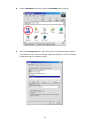
Transfer the system setting info of DVR to another:
Insert the SD card which has stored the system setting info into the DVR.
to enter the setup mode and select the SYSTEM.
Press the Setup button
Highlight SYSTEM and press the Enter button
to enter the SYSTEM SETTING page.
Then set SD SETUP to LOAD.
SYSTEM
MAIN MENU
RECORD
ALARM
CLOCK / TIMER
COMMUNICATION
DISK
SYSTEM
OPERATION LOG
MENU BACKGND
BUZZER
PASSWORD
SETUP PWD
DEFAULT
SD SETUP
VERSION
: ENTER
:2
: ON
: SET
: OFF
: LOAD
: SAVE
: ENTER
MAIN PAGE
VIEW OPERATION LOG
GOTO SYSTEM SETTING
3. Updating System Software (Please refer to section 3.4 for more details.)
4.6 Key Lock Operation
The Key lock operation protects the unit against unauthorized use by disabling the entire front
“<” and
panel controls. Simultaneously press these two
“>” buttons (as shown below) for
at least 3 seconds to lock the unit; to release the Key Lock, simultaneously press these two
buttons again.
Operate
Display
Setup
Search
Enter
Monitor
PLAY
STOP
PAUSE
REC
REV
FWD
DISK
OPERATE
A-rec
T-rec
11
14
* About the location of the buttons, please refer to Page 10 2.1 Front View.
39
5. MENU SETUP
There are 6 categories for operation setting in the setup menu system as shown below. The following
sections will instruct you step by step to configure the operation setting and state each menu’s purpose and
to access the setup menu. Once inside the menu system, the on-screen
options. Press the Setup button
menu allows you to set up the key features of the unit. The functions of various buttons within the
menu-setup mode are described in the paragraphs below.
MAIN MENU
RECORD
ALARM
CLOCK / TIMER
COMMUNICATION
DISK
SYSTEM
KEY FUNCTIONS
Setup button
:
Press to enter the setup menu. Press again to exit the setup mode.
“^” “v” buttons
and
:
Press to select the desired item or entry for setting.
and
“<” “>” buttons
:
Press to highlight the desired option or to select the context for setting.
Enter button
:
Press to enter the selected item and to save the setting.
Shuttle Ring
:
Turn to highlight the desired option or to select the context for setting.
Jog Dial
:
Turn to select the desired item or entry for setting.
* About the location of the buttons, please refer to Page 10 2.1 Front View.
40
5.1 REC SETTING
This page allows you to set the recording rate and recording quality, and enables you to continue
recording when the disk is full.
MAIN MENU
REC SETTING
REC RATE
REC QUALITY
DISK FULL
AUDIO
MULTIPLEXER
RECORD
ALARM
CLOCK / TIMER
COMMUNICATION
DISK
SYSTEM
: 20 F/S
: BEST
: REWRITE
: OFF
: ON
MAIN PAGE
SET REC RATE
GOTO REC PAGE
REC RATE:
This option is for adjusting the number of pictures recorded every second into a storage disk.
The recording rate controls the frequency at which the number of video pictures can be
recorded.
● For a NTSC unit, there are 11 different recording rates you can select from: 60F/S (60 fields
per second), 30F/S, 20F/S, 12F/S, 5.5F/S, 2.4F/S, 1.22F/S, 0.71F/S, 1 F/4S, 1F/6S, and 1F/8S.
● For a PAL unit, there are 11 different recording rates you can select from: 50F/S (50 fields
per second), 25F/S, 17F/S, 10F/S, 5.5F/S, 2.9F/S, 1.52F/S, 0.88F/S, 1 F/4S, 1F/6S, and 1F/8S.
Please refer to the table in section 4.1 for details.
NOTE: The 60 f/s (50 f/s for a PAL unit) recording rate can only function in a 352x240 (352x288
for a PAL unit) resolution
REC QUALITY:
This option determines the image quality to be recorded. The DVR stores images in the
compressed format and allows the image quality to be altered by the image size. There are 4
levels of image quality you can select from: BEST, HIGH, STANDARD, and BASIC. Selecting
the BEST image for use provides higher-resolution recorded images, and normally takes up
more storage space than a HIGH, STANDARD or BASIC image does.
DISK FULL:
This option determines the way to utilize storage media in case of a full disk.
REWRITE: When the hard-disk is full, the device continues recording by displacing the old data.
STOP: When the hard-disk is full, the device will stop recording.
* About the location of the buttons, please refer to Page 10 2.1 Front View.
41
AUDIO:
This option determines the way to record sound if necessary.
ON: Enables AUDIO recording.
OFF: Disables AUDIO recording.
NOTE: Audio function can only be activated in the following refresh rate in NTSC(PAL):
12(10), 5.5(5.5), 2.4(2.9), 1.22(1.52), 0.71(0.88) fields/sec
MULTIPLEXER:
For optimum image recording please set this option to ON when the DVR is connected to a
multiplexer for use. Set this option to OFF when it is only connected to a single camera or
Quad processor.
5.2 ALARM SETTING
This menu allows users to program the configuration of alarm recording only when an alarm input is
activated. The device will record as long as the alarm input is activated.
MAIN MENU
ALARM SETTING
RECORD
ALARM
CLOCK / TIMER
COMMUNICATION
DISK
SYSTEM
ALM OPERATION
REC RATE
REC QUALITY
AUDIO
ALM TYPE
ALM DURATION
PRE- ALARM
: OFF
: 20F/S
: BEST
: OFF
: NO
: 0 SEC
: OFF
MAIN PAGE
GOTO ALARM PAGE
ALARM REC ENABLE
ALM OPERATION:
This option determines whether to activate/deactivate the alarm recording when it detects an alarm input.
ON: The device activates the alarm recording when it detects an alarm input.
OFF: The device ignores the alarm signal when it detects an alarm input.
REC RATE:
This option is for the purpose of adjusting the number of pictures recorded every second into a storage
disk when an alarm input is activated. For a NTSC unit, there are 5 different record speeds you can
select from: 60F/S (60 fields per second), 30F/S, 20F/S, 12F/S, and REMAIN. For a PAL unit, there
are 5 different record speeds you can select from: 50F/S (50 fields per second), 25F/S, 17F/S, 10F/S,
and REMAIN. If you select REMAIN for use, the device will record images at the same speed as set on
the REC page.
* About the location of the buttons, please refer to Page 10 2.1 Front View.
42
REC QUALITY:
This option determines the image quality to be recorded when an alarm input occurs. There are 4
levels of image quality to choose from: BEST, HIGH, STANDARD, and BASIC. The table below shows
the level of image quality with the corresponding compression ratio and image size.
Image Quality
Image Size
Best
Compression Ratio
High
Standard
Basic
48KB
32KB
16KB
21KB
AUDIO:
This option determines the way to record sound if necessary.
ON: Enables AUDIO recording.
OFF: Disables AUDIO recording.
NOTE: Audio function can only be activated in the following refresh rate in NTSC(PAL):
12(10), 5.5(5.5), 2.4(2.9), 1.22(1.52), 0.71(0.88) fields/sec
ALM TYPE:
This option allows users to set a type of alarm input corresponding to the sensor signal in use.
NO: Normally Open. This is to be used with the type of alarm sensor whose contact remains
open in normal conditions and closes in case of activation.
NC: Normally Closed. This is to be used with the type of alarm sensor whose contact remains
closed in normal conditions and opens in case of activation.
ALM DURATION:
This option allows users to set alarms for a certain duration. You can select one of the six following
options: 0 SEC, 30SEC, 1 MIN, 5 MIN, 10 MIN, and NON-STOP.
D uration
Set ting
Alar m r ecor ding
D uration
Alar m
activated
N on-Stop
Alar m
deactivated
Alar m r ecor ding
D uration
Alar m
activated
Alar m
deactivated
R eset
NOTE: Recording may be interrupted at the time of Alarm-in or Alarm-out.
LIVE images may be interrupted at the time of Alarm-out.
43
PRE- ALARM:
This option determines that images prior to an alarm occurs will be recorded in the hard-disk drive.
When an alarm is triggered the device will record the image prior to the alarm for 5 seconds in NTSC
(**20 fields/sec) or 6 seconds in PAL (**17 fields/sec).
ON: Enables this function.
OFF: Disables this function.
NOTE: If the device is already under recording mode before alarm occur, the pre-alarm
recording would not take effect.
** : For NTSC and Mux Off Mode, recording rate 20F/S would be actually 15 F/S
For PAL and Mux Off Mode, recording rate 17F/S would be actually 12.5 F/S.
( This adjustment is to avoid image shaking during playback at the same speed )
44
5.3 CLOCK / TIMER
The DVR provides a weekly table, consisting of two periods of time each day for scheduled
recording. This option allows you to set the time each day that the DVR will start and stop recording.
MAIN MENU
CLOCK / TIMER
RECORD
ALARM
CLOCK / TIMER
COMMUNICATION
DISK
SYSTEM
CLOCK
REC ENABLE
TIMER
: SET
: OFF
: SET
MAIN PAGE
GOTO TIMER PAGE
TIMER REC ENABLE
CLOCK:
This entry allows users to set the system time.
NOTE: Clock data is retained for about 3 months after the 15-hour power supply is used up
(Operate On mode).
REC ENABLE:
This option enables/disables the programmed scheduled recording.
ON: Enables the scheduled recording.
OFF: Disables the scheduled recording.
TIMER:
This entry allows users to program the time each day that the DVR will start and stop recording. There
are two time periods each day available for scheduling. The time is displayed in a 24-hour clock format.
If there is a time overlapping showing between two continual time period settings, the device will
automatically combine the two time-period settings into one combined time-period setting.
REC SCHEDULE
START END
START END
S :06:00-16:00
12:00-18:00
REC SCHEDULE
START
END
S :06:00-18:00
45
START END
00:00-00:00
5.4 COMMUNICATION
This option allows you to configure the status of the RS-232 communication port when connected to an
external device, and the Ethernet communications settings. (Please refer to the RS-232 Protocol and
Network Function for more details)
MAIN MENU
COMM SETTING
RECORD
ALARM
CLOCK / TIMER
COMMUNICATION
DISK
SYSTEM
COMM ID
RS232
RS485
NET ENABLE
NET DHCP
NET IP
FTP SETTING
: 01
: ON
: ON
: OFF
: OFF
: SET
MAIN PAGE
SET RS232 / RS485 ID
GOTO COMM PAGE
COMM ID:
Communication ID for RS-232 and RS-485 communication. After the VR-601 receives a RS-232 or
RS-485 command, it checks if the <Dest ID> within the code is the same as the COMM ID, in which case
the particular command can be accept.
RS-232:
The RS-232 communication port can be either in an importing or exporting mode according to your
applications.
ON: Enables the RS-232 communication port. When you wish the unit to be controlled by an
external device, please select this entry for use.
OFF: Disables the RS-232 communication port.
RS-485:
The RS-485 communication port can be either in an importing or exporting mode according to your
applications.
ON: Enables the RS-485 communication port. When you wish the unit to be controlled by an
external device, please select this entry for use.
OFF: Disables the RS-485 communication port.
NET ENABLE:
This option selects either enable or disable for the Ethernet communication port.
OFF: Disables it.
ON: Enables it.
46
NET DHCP:
This option selects enable or disable for the DHCP communication function.
OFF: Disables it.
ON: Enables it.
NOTE: If provided with a DHCP server, the VR-601 can get an IP automatically by setting this
option to ON.
NET IP:
This option is used to configure the Ethernet communication settings. This is required for the purpose
of making a network connection. Please consult with a qualified MIS professional to configure it.
IP:
XXX.XXX.XXX.XXX
MASK:
XXX.XXX.XXX.XXX
GATEWAY: XXX.XXX.XXX.XXX
FTP SETTING:
This entry allows users to set the FTP File Transfer Protocol.
COMM SETTING
COMM ID
RS232
RS485
NET ENABLE
NET DHCP
NET IP
FTP SETTING
FTP SETTING
: 01
: ON
: ON
: OFF
: OFF
: SET
ENABLE
REC MODE
REC RATE
ACCOUNT
MAIN PAGE
: OFF
: ALARM REC
:1F/1S
: SET
MAIN PAGE
SET FTP ON / OFF
NAS FTP RECORDING
ENABLE:
This option is to select enable or disable for the FTP function.
ON: Enables it.
OFF: Disables it.
REC MODE:
This option determines the recording mode to be recorded when the FTP function occurs. There
are 2 levels of recording mode to choose: ALARM REC and ALL REC.
ALARM REC: Only to record the alarm-event recorded video.
ALL REC: To record all the recorded video.
47
REC RATE:
This option determines the recording rate to be recorded at when the FTP function occurs. There
are 4 levels of recording rates to choose from: 1 F / 1 S, 1 F / 10 S, 1 F / 30 S and 1 F / 60 S.
NOTE: An actual transfer interval could be stretched in some environment.
ACCOUNT:
This option is used to configure the FTP account settings. This is required for the purpose of
making a FTP connection. Please consult with a qualified MIS professional to configure it.
FTP ACCOUNT
FTP IP
:
USER
:
PASSWORD :
PATH
:
192.168.001.128
[ dvr
]
[ 00000000
]
[ /dvrvideo
]
FTP IP : Every FTP server has to own an IP address to be identified on the network. Input
the IP address of the FTP server.
USER : Input the FTP user name (Login Name).
PASSWORD : Input the FTP password (Password).
PATH : Input the upload path while doing the FTP.
NOTE: For valid settings, please reboot the DVR after changing the FTP ACCOUNT.
48
5.5 DISK SETTING
MAIN MENU
DISK SETTING
RECORD
ALARM
CLOCK / TIMER
COMMUNICATION
DISK
SYSTEM
REFORMAT
HD 2 USAGE
BACKUP
GOTO DISK PAGE
DISK REFORMAT/CLEAR
: HD 1 2
: REC
: FULL
MAIN PAGE
REFORMAT:
This option allows you to clear out all the data in the hard-disk drive. You will be required to enter the
pre-set password before proceeding with clearing out the data. Enter the standard password “9999” if you
don’t set your individual password. To set your individual password, please refer to section 5.6
PASSWORD option.
HD 1 2:
Clears out all the data stored in HD 1 and HD 2.
BACKUP HD:
Clears out all the data stored in HD 2, which is set to backup purpose only. (This
function has to be proceeded with when the HD 2 USAGE option is set to
BACKUP.)
HD2 USAGE:
This option determines the way to utilize the hard-disk drive in the mobile compartment.
BACKUP: Used for data backup only, which will not be part of regular recording hard-disk drive.
REC: Used for the regular recording hard-disk drive.
NOTE: When you wish to play back a recorded video from a HD2, this option must be set to
REC. For more details, please refer to section 4.3.4.
BACKUP:
This function allows you to duplicate data from HD 1 to HD 2. Please set HD 2 as BACKUP first. (For
operation details, please refer to section 4.5.1)
FULL: Duplicates all the recorded video from HD1 to HD2.
ALARM: Duplicates all the alarm-event recorded video from HD 1 to HD2
SELECT: Duplicates a particular recorded video from HD1 to HD2.
49
5.6 SYSTEM
This page is used for accessing the history of the operation status, setting the password, resuming
factory default, and determining the menu display background.
SYSTEM
MAIN MENU
OPERATION LOG
MENU BACKGND
BUZZER
PASSWORD
SETUP PWD
DEFAULT
SD SETUP
VERSION
RECORD
ALARM
CLOCK / TIMER
COMMUNICATION
DISK
SYSTEM
: ENTER
:2
: ON
: SET
: OFF
: LOAD
: SAVE
: ENTER
MAIN PAGE
VIEW OPERATION LOG
GOTO SYSTEM SETTING
OPERATION LOG:
This log shows the history of the operation status in chronological order. What the following entries
represent is detailed below.
ON: Powers up the device.
OFF: Powers off the device.
05/15/03
05/15/03
05/15/03
05/15/03
05/15/03
05/15/03
05/15/03
05/15/03
REC: Starts recording.
STOP: Ceases recording.
PLAY: Shows recorded video.
V-IN: Video input is connected.
V-LOSS: Video loss occurs.
18:19:32 ON
18:19:32 OFF
18:19:32 REC
18:19:32 STOP
18:19:32 PLAY
18:19:32 V-IN
18:19:32 V-LOSS
18:19:32 P-LOSS
P-LOSS: Power interruption occurs.
A-IN: Detects an alarm input.
LOCK: Disables the entire front panel controls.
UNLOCK: Releases the key lock.
UPDATE: Updates system software.
Note: The log keeps an operation history on a revolving basis because of a limit is 4000. When the
log is full, the newly registered record of an operation will replace the existing records from
the oldest one.
50
MENU BACKGND:
There are 3 levels of background color transparency, you can choose from : level 1 is totally
transparent, level 3 is opaque, and level 2 is between level 1 and 3. The background color is used
in setup menu and search function.
BUZZER:
This option determines the embedded buzzer sounding a tone to signal the following situations. A
tone lasts about two seconds long.
ON: Enables buzzer.
OFF: Disables buzzer.
Situation
Alarm occurs
Video loss occurs
Disk is full
Load factory default
Buzzer set to ON
Enable/disable key lock function
Power on /off mobile rack HDD
Backup operation complete
Timer activate/deactivate
Recording switching between HDD
PASSWORD:
This option allows you to set a password to prevent any unauthorized re-formatting of the
hard-disk drives or use by a network viewer. The standard password is “9999”.
OLD PASSWORD: Enter the pre-set password (or the standard password if this is the initial
setting) to access the password setting system.
NEW PASSWORD: Enter a 4-digit-number password of your choosing which will replace
the pre-set password (or the standard password “9999”).
SETUP PWD:
When this option is on, user must pass the password check before entering the setup menu.
ON: Enables it.
OFF: Disables it.
DEFAULT:
This option allows you to reload the factory default setting. Please do note that the password can
not be changed in the factory default setting.
51
SD SETUP:
The VR-601 offers a quick setup method by using a SD card. If the user wants to set up many a
number of the same devices with the same settings, he can save the whole settings to a SD card,
then transfer to another DVR.
SAVE: Saves the whole setting to the SD card.
LOAD: Loads the whole setting from the SD card.
VERSION:
This item is in the setup menu reveal network MAC, BIOS version, and software version, and last
updated date.
MAC : 00 : 0c : 0c : 00 : 00 : 07
BIOS : 1.05
SW
: 1.00J
DATE : Jun 9 2003
52
6. RS-232 & RS-485 Protocol
6.1 Setup
6.1.1 Use a Null Modem cable (the standard RS-232 9 Pin Cable with Pin 2 and Pin 3 exchanged, see pin
configuration chart below for details) to connect the COM 1 on the rear panel of the DVR to a PC.
6.1.2 Set the RS-232 option to ON in the COMMUNICATION page of the setup menu.
6.1.3 Set the PC communication parameters: 9600 bps, No Parity, 8 Data Bits, 1 Stop Bit.
6.2 Communication Protocol:
6.2.0 General Command Format
<Lead Code = 0x41>, < Dest ID >, < Src ID >, <Main category >, <Second category >, {<Number of
parameters>,<Parameter 1>, <Parameter 2> ..,} <End Code= 0x4f>
Lead Code = 0x41
Dest ID
= 0x01
Src ID
= 0x20
Main Category = 0x01
= 0x02
Second Category
Keys and Signals
Command
= 0x01 Handshake
= 0x02 Request Time/Set Time
= 0x06 Request System State
End Code= 0x4f
53
The different command types and their corresponding parameters are as follows:
6.2.1 Keys and signals
PC Send: <0x41>, <0x01>, <0x20>, <0x01>, <Key Value>, <0x4f>
< The value of a specific front panel key >
KEY_PLAY
1
KEY_STOP
3
KEY_PAUSE
4
KEY_POWER
5
KEY_REC
6
KEY_SETUP
7
KEY_ENTER
8
KEY_SEARCH
10
KEY_DISPLAY
11
KEY_UP
13
KEY_DOWN
14
KEY_LEFT
15
KEY_RIGHT
16
KEY_MONITOR
36
JOG_L
128
JOG_R
129
KEY_SHUT_L8
130
( -100x, -1/16x )
KEY_SHUT_L7
131
( -100x, -1/16x )
KEY_SHUT_L6
132
( -30x, -1/8x )
KEY_SHUT_L5
133
( -16x, -1/8x )
KEY_SHUT_L4
134
( -8x, -1/4x )
KEY_SHUT_L3
135
( -4x, -1/4x )
KEY_SHUT_L2
136
( -2x, -1/2x )
KEY_SHUT_L1
137
( -1x, -1/2x )
KEY_SHUT_CT
138
KEY_SHUT_R1
139
( 2x, 1/2x )
KEY_SHUT_R2
140
( 4x, 1/2x )
KEY_SHUT_R3
141
( 8x, 1/4x )
KEY_SHUT_R4
142
( 16x, 1/4x )
KEY_SHUT_R5
143
( 30x, 1/8x )
KEY_SHUT_R6
144
( 100x,1/8x )
KEY_SHUT_R7
145
( 100x,1/16x )
SIGNAL_REC_IN
163
SIGNAL_ALARM_RESET
165
SIGNAL_REC_OUT
169
SIGNAL_ALARM_IN
189
*About (A, B), A means the speed of FAST playback, B means the speed of SLOW playback.
54
6.2.2 COMMAND Types
6.2.2.0 Command (Main Category=0x02)
6.2.2.1 Handshake (Second Category=0x01)
PC Request: <0x41>, <0x01>, <0x20>, <0x02>, <0x01>, <0x00>, <0x4f>
DVR Response: <0x41>, <0x20>, <0x01>, <0x02>, <0x08>, <0x00>, <0x4f>
6.2.2.2 Request Time (Second Category=0x02)
PC Request: <0x41>, <0x01>, <0x20>, <0x02>, <0x02>, <0x00>, <0x4f>
DVR Response: <0x41>, <0x20>, <0x01>, <0x02>, <0x02>, <0x07>, <7 Time Value >, <0x4f>
The following case is an illustration of < 7 Time Value>
2001/06/20 17:05:00 = <0xD1>, <0x07>, <0x06>, <0x14>, <0x11>, <0x05>, <0x00>
6.2.2.3 Set Time (Second Category=0x02)
PC Request: <0x41>, <0x01>, <0x20>, <0x02>, <0x02>, <0x07>, < 7 Time Value >, <0x4f>
The following case is an illustration of < 7 Time Value>
2001/06/20 17:05:00 = <0xD1>, <0x07>, <0x06>, <0x14>, <0x11>, <0x05>, <0x00>
DVR Act: Changing the time and date.
NOTE: The date (year, month and day) may not be set by RS-232. In this case,
please set at the desired date after setting the date at different year, different
month and different day.
6.2.2.4 Request State (Second Category=0x06)
PC Request: <0x41>, <0x01>, <0x20>, <0x02>, <0x06>, <0x00>, <0x4f>
DVR Response: <0x41>, <0x20>, <0x01>, <0x02>, <0x06>, <0x01>,
<System State = 0..>, <0x4f>
Description of <System State>:
STATE_STOP
0
STATE_REC
1
STATE_PLAY
3
STATE_SETUP
6
STATE_SEARCH
7
STATE_BACKUP
15
STATE_NET_PLAY
23
6.2.2.5 Time Search (Second Category=0x0b)
PC Request: <0x41>, <0x01>, <0x20>, <0x02>, <0x0b>, <0x06>, <6 Time Value >, <0x4f>
where < 6 Time Value > = year ( 2 bytes, = LowByte + HighByte*256 ), month ( 1 byte),
day (1 byte), hour(1 byte),min(1 byte)
Example: to search 06/12/2002 17:00 the Time Value =
<0xd2>,<0x07><0x06>,<0x0b>,<0x11>,<0x00> where 2003= 210(=0xd3) + 7(=0x07) *256
NOTE: The DVR accepts RS-232 time search commands only under the live or playback
Mode.
55
7. Mobile Rack Installation
Usually, the unit comes with one hard-disk drive installed in compartment HD 1, which is
default-configured as a master. The jumper settings configuration of the installed hard-disk drives for
the unit and compatible drives which can be used with this unit are listed in the table below. To install
a hard-disk drive in compartment HD 2, please take the following steps.
The jumper settings of hard-disk drives for the system
Location
Jumper
IDE 1
Compartment HD 1
Master
IDE 2
Compartment HD 2
Master
1. Make sure that the key unlocked.
2. Pull the active-handle outward to remove the carrier body away from
the mobile rack
3. Slide the top cover backward and remove.
4. Setting the jumper of your hard-disk drive. The way to set the jumper
of the drive varies between manufacturers; please refer to the
instructions on the drive to set the jumpers in the master position.
56
5. Attach the interface connector and the power connector to the drive.
Please note the red lining of the IDE cable and the red wire of power
cable must line up side by side.
6. Place the hard-disk drive inside mobile rack, Use four of the provided
screws.
7. Place the top cover back to the carrier body by sliding forward to
secure.
8. Slide the carrier body back in the mobile rack.
9. Push the carrier body further into the mobile rack until fully inserted.
57
10. Push the active-handle inward.
11. Lock the Key.
58
8. System Default
MAIN MENU
REC SETTING
RECORD
ALARM
CLOCK / TIMER
COMMUNICATION
DISK
SYSTEM
REC RATE
REC QUALITY
DISK FULL
AUDIO
MULTIPLEXER
: 20 F/S
: BEST
: REWRITE
: OFF
: ON
MAIN PAGE
SET REC RATE
GOTO REC PAGE
MAIN MENU
ALARM SETTING
RECORD
ALARM
CLOCK / TIMER
COMMUNICATION
DISK
SYSTEM
ALM OPERATION
REC RATE
REC QUALITY
AUDIO
ALM TYPE
ALM DURATION
PRE- ALARM
: OFF
: 20F/S
: BEST
: OFF
: NO
: 0 SEC
: OFF
MAIN PAGE
GOTO ALARM PAGE
ALARM REC ENABLE
MAIN MENU
CLOCK / TIMER
RECORD
ALARM
CLOCK / TIMER
COMMUNICATION
DISK
SYSTEM
CLOCK
REC ENABLE
TIMER
MAIN PAGE
GOTO CLOCK / TIMER PAGE
TIMER REC ENABLE
59
: SET
: OFF
: SET
MAIN MENU
COMM SETTING
RECORD
ALARM
CLOCK / TIMER
COMMUNICATION
DISK
SYSTEM
COMM ID
RS232
RS485
NET ENABLE
NET DHCP
NET IP
FTP SETTING
: 01
: ON
: ON
: OFF
: OFF
: SET
MAIN PAGE
GOTO COMM PAGE
SET RS232 / RS485 ID
MAIN MENU
DISK SETTING
RECORD
ALARM
CLOCK / TIMER
COMMUNICATION
DISK
SYSTEM
REFORMAT
HD 2 USAGE
BACKUP
: HD 1 2
: REC
: FULL
MAIN PAGE
DISK REFORMAT/CLEAR
GOTO DISK PAGE
SYSTEM
MAIN MENU
OPERATION LOG
MENU BACKGND
BUZZER
PASSWORD
SETUP PWD
DEFAULT
SD SETUP
VERSION
RECORD
ALARM
CLOCK / TIMER
COMMUNICATION
DISK
SYSTEM
: ENTER
:2
: ON
: SET
: OFF
: LOAD
: SAVE
: ENTER
MAIN PAGE
GOTO SYSTEM SETTING
VIEW OPERATION LOG
60
9. O.S.D Message
No.
O.S.D Message
Meanings
1
NO DISK
No hard-disk detected after power activated
2
BATTERY LOW
Suggest change the battery and reset the system time
3
LOADING
System Boot up
4
VIDEO LOSS
Video loss
5
VIDEO IN
Video input source
6
KEY LOCKED
Key lock function is on
7
KEY UNLOCKED
Key lock function is off
8
n1 OF n2 ITEMS PROGRESS n3 %
BACKUP n1/n2 NOW n3 %
9
BACKUP COMPLETE
Backup complete
10
HD2 SPACE NOT ENOUGH
HD2 has not enough space for backup
11
NO RECORD FOR BACKUP
12
BACKUP INCOMPLETE
13
NOT FOUND
No backup is possible.
Backup incomplete, since the user has pressed the STOP
button to stop it
The system cannot find a video in the Search function.
14
END
15
DISK FULL
16
EMPTY
17
SET TO NTSC, PLS RESTART
System has to be set to NTSC, please reboot (PAL is similar)
18
SOFTWARE UPDATE
Software update
19
PLEASE RESTART
20
NO DISK
21
DATA NOT CONTINUOUS
22
DISK ATTACHED
HD2 has been attached.
23
DISK REMOVED
HD2 has been removed.
24
FAN STOPPED
The chassis fan has stopped for over 30 seconds.
25
HDn ERROR AT xxxxx
26
NOT PRESENT
27
SAVE TO DISK
Start saving to the JPEG file.
28
SAVE TO Fnnn. JPG
Save to Fnnn. JPG (where nnn= 0..999)
29
SAVE OK
Save to the JEPG is ok.
30
SD CARD WRITE PROTECT
A SD card is write-protected; or there is an error
Playback of recorded video has reached the end point
Hard-disks are full; this happens only when the DISK FULL
item in the setup menu is set to STOP.
The user presses the PLAY button or uses the SEARCH
function, but no video can be played.
The system should be rebooted after the software has been
updated
The user has pressed the Save key without putting in a SD
card, or there is a disk error.
The system finds data in installed HDs cannot be used
contiguously. Suggest you remove HD2 from the system.
There is a hard-disk error during recording, where n is the
hard-disk number and xxxxx is the hexadecimal location.
When the user tries to clear a disk that was not attached in
the setup menu.
61
10. Network Viewer and Image Viewer
This section provides instructions for installing and using the Network Viewer, and Image Viewer,
which are included with the VR-601. The programs can be operated by a selected PC equipped with
the following requirements.
1. Intel Pentium 233MHz at least.
2. 32 MB RAM
3. Window 95, 98, NT, ME, 2000 and XP.
4. 4 MB Video card capable of 24-bit true color display.
5. 5 MB free hard-disk space for software installation.
6. 10-base T network for LAN operation.
10.1 The Network Viewer
10.1.1 Introduction to Network Viewer
The Network Viewer allows you to potentially access 16 units of the VR-601 from a remote
desktop or a laptop in a TCP/IP networking environment. It can perform the following functions.
View live images from the VR-601
Store, search, and review recorded video from the VR-601 HDD.
Change the regular record, event record, and timer properties.
Before you are ready to view images from a desktop, you need to have your VR-601 networked
by obtaining a 10 base Ethernet data cable (Standard RJ-45) to connect the VR-601 to your
LAN/WAN. Now enter the main menu to set the IP address.
RJ-45
PC
VR-601
RJ-45 PIN configuration for Ethernet
PIN NO.
1.
2.
3.
4.
5.
6.
7.
8.
PIN Assignment
TX +
TX RX +
Not Connected
Not Connected
RX Not Connected
Not Connected
62
RJ-45 socket
12345678
Physical specification for Ethernet
Wire Type
Connector Type
Max. Cable Length
Hub Wiring Configuration
PC Wiring Configuration
Cat. 5
RJ-45
30 m
Straight Through
Cross Over
NOTE: For more details on network connections, please refer to the following document.
10.1.2 Install the Network Viewer in your PC
Install the Network Viewer from the supported CD-R.
1. Exit all applications currently running in the selected PC.
2. Insert the supported CD-R in the CD-ROM drive. The program will execute the installation
automatically. Follow the on-screen instructions to proceed with the rest of the installation
procedure as they appear.
3. After the installation is complete, pop up the START menu from your computer, and point to
Programs / JVC Picture Viewer to open up the program selection page as shown below.
Click the Network Viewer tag to start the Network Viewer program.
NOTE: If the Network Viewer needs to be upgraded, please contact your JVC dealer.
NOTE: Please make sure the TCP/IP communication software has been properly set and
configured in your computer. To check your TCP/IP settings, refer to the following
document.
63
10.1.3 View the VR-601 video from a remote PC
Follow the instructions below to use the Network Viewer to browse a VR-601 video from a
remote location. Upon entering the Network Viewer; the connection box will appear as follows.
1. Choose a channel number from the Channel drop-down list.
2. Assign a name for the chosen VR-601.
3. Type in the password and IP of the device and click the Add tag to add the device to the
connection list.
4. Click the Connect tag to establish the connection between the devices and the computer.
Click OK to begin viewing images.
NOTE: Upon connection, the connection status box indicates the name and IP address
of the selected device. If there’s a failure to connect, a “Fail” message appears
on the screen right after the device IP address; otherwise an “OK” appears. To
add more connections or units to the VR-601, please repeat the above
instructions.
Functions
Channel
Name
Password
URL of the Remote Device
URL of a Proxy
Port
Modify
Delete
Connect
OK
Cancel
Description
Assign a display location when you have multiple devices connected.
This box allows you to assign a name to the chosen device.
Type the preset password for making a connection.
Type the IP address which you preset for the device
Type your proxy server address when accessing the Internet via a proxy
server.
Enter the designated port setting of your proxy server.
Click to change the settings of a chosen device.
Click to remove the connection of a chosen device
Click to establish the connection between the devices and the computer.
Click to access the display page of the Network Viewer
Click to exit the program of the Network Viewer.
64
Viewing images
View all the connected devices
Once the connection has been established, click OK to enter the Multi-device mode window.
(See the sample screen below) This window displays all the connected devices in the
sequence which has been arranged when you established the connection.
Function Buttons
Description
Split-Screen display function bar. This allows you to display the connected
device in multi-format screens of 1, 2x2, 3x3, and 4x4.
Press to enter the selected device (the Single device display mode). Select
a device from the DEVICE LIST box to enable this button.
Press to open the device setting page to add more devices for viewing.
Press to leave the Network Viewer program.
Connected devices display box. This box indicates the title and IP address
of all connected devices.
Device title and image display area. Displays the title of each connected
device and the time/day information of each displayed image on the top
blue bar.
65
View single device
Follow any one of the instructions below to get into the single device mode.
1. Select the desired device from the DEVICE LIST box on the Multi-device Mode. The
button will enable. Click the button to view the image of the selected device and have
access to certain functional operations of the device via the network. (See the sample
screen below.)
2. Double click the image display area of each screen.
NOTE: The Network Viewer may not play back a recorded video when the number of the
index table reached to 3000. In such case, please reboot the VR-601 for regular
playback.
NOTE: The Network Viewer may not play back the video what is recorded at 1/8 F/S. In such
case, please play back picture-by-picture by using the Step button.
66
Function Buttons
Description
Playback function bar.
Play- Click to play back a recorded video from the PLAY LIST.
Pause- Click to freeze the image.
Stop- Click to stop playing back the recorded video or cease
recording.
REC- Click to activate the recording function of the device.
Step- Click to view images picture-by-picture.
Click to return to the Multi-Device mode.
Click to save a viewing image in the local computer.
Click to enter the SETUP page, which allows you to program the
recording rate, recording quality, and schedule recording.
Click to exit the Network Viewer program.
Multiplexer format list box.
Select a MUX from the drop-down list which is connected with the
DVR, so the Network Viewer will be able to display cameras in
corresponding to the camera input of the Multiplexer. If your MUX
isn’t available, please select the Other Multiplexer option for use.
The Viewer will display cameras in the thumbnail format.
(Sequentially displaying images will appear one after another in the
adjacent display window)
Recorded video list box. This box allows you to access all recorded
video, which are stored in the HDD of the connected devices. To
review a recorded video, just click an entry from the list and click
button.
the
PgUp/PgDn: To scroll up and down the list.
VR-601 Status Box. This box indicates the selected device status.
PLAY: The device is in the playback mode.
LIVE: The device is in the live display mode.
WAIT: The device is processing the command.
PAUSE: Pauses the image.
This allows you to search a recorded video kept in the HDD of the
device. Enter the MONTH/DAY/YEAR HOUR: MINUTE you wish to
search and click GO to proceed.
Split-Screen display function bar. This allows you to display the
selected device in multi-format screens of 1, 2x2, 3x3, and 4x4.
Image display area. Displays the images of each camera and the
title and time/date information on the top blue bar. Double click the
image to view a full screen of the camera.
67
10.1.4 Change the Record & Timer Properties Via the Network
Follow the instructions below to reconfigure the record and schedule recording settings via the
network.
A.
Set the regular record settings
1. When in the single –device mode, click
to enter the SETUP page. (See the sample
screen as in A above)
2. Select a desired recording RATE and QUALITY from the corresponding drop-down list
3. Click the OK tag to proceed.
Set the Alarm record settings
1. When in the single –device mode, click
to enter the SETUP page. (See the sample
screen as in A above)
2. Set the ALARM SETTING to ON to enable the drop-down list in the ALARM SETTING
area.
3. Select a desired recording RATE and QUALITY from the corresponding drop-down list.
4. Click the OK tag to proceed.
Set the record timer
1. When in the single –device mode, click
to enter the SETUP page. (See the sample
screen as in A above)
2. Set the RECORD TIMER to ON to enable the RECORD TIMER setting area. The MODIFY
button will appear.
3. Click the MODIFY button to set the schedule for recording for each day. (See the sample
screen below) Go to both the START TIME & END TIME boxes, enter a specific Hour:
Minute and click OK to return to the SETUP page.
4.When all required settings are completed, click OK to proceed.
68
10.1.5 Archive Images to the Computer
Playback images can be stored in a local PC in the JPEG format. Follow the instructions below to
save the viewed images to your PC.
1. Press
during playback to freeze the desired image.
2. Press
to enter the following sample screen.
3. Select a folder in the computer for copying images in.
4. Enter the number of images into the NUMBER OF SAVING box you wish to save in.
5. Click the SAVE tag; the program will automatically copy the displayed images into the
designated folder. The images are saved in the DVRxxx.jpg file name, which is displayed in the
box on the right-hand side. To view a saved image, please follow the instructions in the next
section to proceed.
69
10.2 The Image Viewer
This is image integrity-protect software. It not only allows you to view an archived image from
the SD card or HDD of a computer, but also protects an archived image from reproduction or
interpolation. If an image isn’t in the original format made by a VR-601, the Image Viewer won’t
display the image and instead will send a warning message” Wrong File, Can’t Open”. Follow
the instructions below to open an archived image from a SD card or a HDD.
1. Pop up the START menu from your computer, and point to Programs/JVC Picture
Viewer to open up the program selection page. Click the Image Viewer tag to start the
Image Viewer program. (See a sample screen below.)
2. Select a folder where the files are kept and click a file you wish to display from the
upper-right box or click the AUTOPLAY tag to display automatically all the files in the
selected folder. Each file will be displayed for 2 seconds on the screen.
3. Click the PRINT tag to get a displayed image printed out from a printer.
70
11. Index Table
The following description details how the DVR manages an index table issue.
The DVR will generate a time index table indicating recorded data is kept in a particular HDD. This
allows to individually selecting recorded data to be displayed via the alarm list search and full list
search. The maximum number of lists, for a given HDD, is 3000. When the list of any given HDD is
used up-and the disk is not full, The unit will still use the rest of the space for recording. In such a
case, an index for the recent recorded data will be generated and the index of the next oldest data
will be erased so that the list does remain 3000 in total. And the next oldest data will be kept in the
index of the corresponding oldest data. For any newly-recorded data, this approach will be applied
until the disk becomes full.
HD1
1
2
3
3000 LISTS
HD1
1
2
12-02-02 12:20:55
12-02-02 13:30:33
01-30-03 16:00:34
:
:
:
3000 02-03-03 16:00:56
2999
3000
12-02-02 12:20:55
01-30-03 16:00:34
:
:
:
02-03-03 16:00:56
02-08-03 17:30:58
3000 LISTS
In the rewrite recording mode, when the archived hard-disk drive is full, the DVR will start overwriting
the oldest data recorded. As the previous recorded data was partially overwritten by the recent
recording, the indicating time index of that data will be changed corresponding to the starting time of
the remaining session. The index of the session will be deleted from the table when it is fully
overwritten.
Previously
recorded data
overwritten
The point stops recording
Previously recorded data remaining
END
In the rewrite recording mode, the DVR will generate a
new index at the time returning to the TOP from the
END of HDD. In this place, the images should not be
played continuously.
71
TOP
12. Network Configuration
12.1 Cable Connections
Please follow the instructions below to connect your DVR to a computer or a network and to choose
a proper RJ-45 cable configuration for connections.
Physical specification of RJ-45 cable for Ethernet
Wire Type
Cat. 5
Connector Type
RJ-45
Max. Cable Length
30 m
Hub Wiring Configuration
Straight Through
PC Wiring Configuration
Cross Over
12.1.1 Connect to a computer
Use a crossover LAN cable to connect directly to a computer.
SD Card
VIDEO
FROM MUX
MAIN MONITOR
AUDIO
IN
RS-485
IN
ETHERNET
10/100
RS-232
OUT
OUT
TO
MUX'S VCR IN
TO
MONITOR
ALARM
I/O
DC12V
RJ-45
CROSSOVER CABLE
12.1.2 Connect to a LAN Hub (INTRANET)
The RJ-45 PIN configuration for connecting with a LAN Hub is shown below.
SD Card
VIDEO
FROM MUX
MAIN MONITOR
AUDIO
IN
RS-485
IN
ETHERNET
10/100
RS-232
OUT
OUT
TO
MUX'S VCR IN
TO
MONITOR
ALARM
I/O
DC12V
RJ-45
72
RJ-45 PIN configuration for LAN Hub
PIN NO.
1.
2.
3.
4.
5.
6.
7.
8.
PIN Assignment
TX +
TX RX +
Not Connected
Not Connected
RX Not Connected
Not Connected
RJ-45 socket
12345678
12.1.3 Connect to WAN (INTERNET)
The RJ-45 PIN configuration for connecting to a WAN is the same as connecting to a LAN.
SD Card
VIDEO
FROM MUX
MAIN MONITOR
AUDIO
IN
IN
ETHERNET
10/100
RS-232
OUT
OUT
TO
MUX'S VCR IN
RS-485
TO
MONITOR
ALARM
I/O
DC12V
RJ-45
12.2 Configure Your DVR Network Settings
Upon network hardware connection, you need to activate the network function and configure
the proper network settings of the DVR.
12.2.1 Enable DVR Network Function
MAIN MENU
COMM SETTING
RECORD
ALARM
CLOCK / TIMER
COMMUNICATION
DISK
SYSTEM
COMM ID
RS232
RS485
NET ENABLE
NET DHCP
NET IP
FTP SETTING
MAIN PAGE
ETHERNET ENABLE
GOTO COMM PAGE
Press the Setup button
and
: 01
: ON
: ON
: ON
: OFF
: SET
to enter the MAIN MENU. Please use the“<” “>” buttons
to highlight COMMUNICATION; then press the Enter button
to enter
the COMM SETTING page.
Use the “^” “v” buttons
press the Enter button
and
to highlight NET ENABLE; select ON. Then
to proceed.
* About the location of the buttons, please refer to Page 10 2.1 Front View.
73
12.2.2 Enable DHCP Function
Use the “^” and “v” buttons
, and
, to highlight NET DHCP; select ON. Then
to proceed.
press the Enter button
MAIN MENU
COMM SETTING
RECORD
ALARM
CLOCK / TIMER
COMMUNICATION
DISK
SYSTEM
COMM ID
RS232
RS485
NET ENABLE
NET DHCP
NET IP
FTP SETTING
GOTO COMM PAGE
SET ETHERNET DHCP
: 01
: ON
: ON
: ON
: ON
: SET
MAIN PAGE
NOTE: This function can only work if the LAN which the unit is connected to has a DHCP
server. If the DHCP server is working, the DVR will obtain an IP address automatically
from the DHCP server. In that case please skip the section 2.3 (Set IP address) and
follow section 3. (TCP/IP Communication Software).
12.2.3 Set IP Address
You don’t need to set a NET IP for the unit if the LAN which the unit is connected to has a
DHCP server. Otherwise, please follow the instructions given below:
MAIN MENU
COMM SETTING
RECORD
ALARM
CLOCK / TIMER
COMMUNICATION
DISK
SYSTEM
COMM ID
RS232
RS485
NET ENABLE
NET DHCP
NET IP
FTP SETTING
MAIN PAGE
SET ETHERNET
GOTO COMM PAGE
Use the “^” and “v” buttons
: 01
: ON
: ON
: ON
: ON
: SET
, and
, to highlight the NET IP. Press the Enter button
to enter the NET IP page
Set the IP, MASK and GATEWAY. Then press the Enter button
following is a sample setting.
IP:
192.168.0.1
MASK:
255.255.255.0
GATEWAY:
0.0.0.0
* About the location of the buttons, please refer to Page 10 2.1 Front View.
74
to proceed. The
NOTE: When only one unit of the DVR is connected to a computer or LAN, you can
freely assign an IP address for the DVR. For example, there is a range of DVR IP
addresses from 192.168.0.1 to 192.168.0.255. You can pick one for use from the
range of the IP. It’s not necessary to set MASK and GATEWAY; leave the settings
as default.
When a DVR is connected to a WAN, you must acquire a unique, permanent IP
address and correctly configure the MASK and GATEWAY settings according to
your network architecture. If you have any questions regarding those settings,
please contact a qualified MIS professional or your ISP.
NOTE: When connecting to a network, each connected DVR must be assigned a unique
IP, which must be in the same class type as your network address. IP addresses
are written as four sets of numbers separated by periods; for example,
192.168.0.1 Therefore, if the connected network is identified as Class C, for
example, the first three sets of numbers of the DVR IP address must be the same
as the network address. If the connected network is identified as Class B, the
first two sets of numbers of the DVR IP address must be the same as the
network address. If you have any questions regarding these settings, please
contact a qualified MIS professional or your ISP.
12.3 TCP/IP Communication Software
Follow the instructions below to install the TCP/IP communication program into your computer.
Click the Start Menu from your computer, and point to the Settings/Control panel.
75
Click the NETWORK icon twice to enter the NETWORK setting windows.
Click on the Configuration tag; check if the TCP/IC is included among the network
components list. If the TCP/IP is included, please process step 5. If it is not included,
please follow step 4 to install the TCP/IP.
76
12.4 TCP/IP installation
During the installation, you will be requested to insert the windows CD-ROM. After
installation, the PC will be restarted.
12.5 TCP/IP Configuration setting
Click Start
Settings
Control Panel
Network.
Select TCP/IP, and then click Properties.
Before processing the DVR installation in a WAN, please make sure the Internet
connection works properly. If not, please contact your ISP provider.
77
If you are using a DHCP server, please select Obtain an IP address automatically. Any
assigned IP address for the connected DVRs must be in the same class type as the server.
If there is no DHCP server, please select specify an IP address and type in the IP address
of your PC. This IP address must be different from the DVR IP but in the same class type.
NOTE: The IP address of a DVR in a network must be unique to itself as opposed to
those of the other chosen PCs, but in the same class type
12.6 Connection Testing
With the previous settings, follow the instructions below to ensure whether you have established
the connection successfully.
Click Start
Programs
MS-DOS Prompt
Type in ping 192.168.0.1 then Enter. (See the sample screen below)
** This IP is the DVR IP address that is assigned for the connected DVR in step 2.
78
If you receive a response as in the sample screen below, the connection hasn’t been
successfully established. Please re-check all the hardware and software installation by
repeating steps 1 to 5. If you still can’t establish the connection after rechecking, please
contact your dealer.
If you receive a response as in the sample screen below, you have successfully made the
connection.
79
13. SPECIFICATIONS
Model Number
Image System
Resolution
Video In
Video Out
Audio In/Out
VR-601 U
VR-601 E
NTSC
PAL
720 x 240 pixels
352 x 240 pixels
720 x 288 pixels
352 x 288 pixels
Composite Video In (BNC) x 1, Multiplexer Monitor In (BNC) x 1
Composite Video Out (BNC) x 1, Multiplexer Monitor Out (BNC) x 1
Line In / Out (RCAx2), 16 bits, 8 kHz
Storage Media
80 GB (can be increased up to 240 GB)
Compression
MJPEG
Memory Card
SD Card
Archive
Hot Swappable Removable HD
Watermark
Recording Rate
Image Size
Digital Signature
30 ips (720x240)
60 ips (352x240)
25 ips (720x288)
50 ips (352x288)
Best(48KB) / High(32KB) / Standard(21KB) / Basic(16KB)
Recording Mode
Schedule / Manual / Alarm / Circular
Alarm Recording
Event / Pre-Alarm / Post Alarm
Pre-Alarm Recording
Playback Speeds
Record Search
100 pictures
Frame Stepping, 1/16x,1/8x,1/4x,1/2x,1x,2x,4x,8x,16x,30x,100x
Alarm / Time / Event list / Filter(thumbnail) / SD card
Set-up Menu
Multi-layer / Network setting
Log list
4000 records
Alarm In/Out
1 Alarm Input / Output
Built-in Buzzer
Yes
Communication Port
RS-232, RS-485, and Ethernet Port
Network Interface
Ethernet (RJ-45 10/100 base-Tx) x 1
Network Protocol
TCP/IP, DHCP, HTTP, UDP, FTP, PPP
Software Upgrade
Upgrade via Memory Card(SD Card) or RS-232
Password Protection
Operation / Menu Setup / Remote Access
Network Capabilities
Archive image as JPEG formats,
Multi-brand multiplexer decoding,
Remote live or recorded images
Power Supply (AC adapter)
Dimensions
Input: 100V-240V, 50 Hz/60 Hz; Output: DC12V max 5A
220 mm x 94 mm x 340 mm EIA 19" 2U Half Size Mountable
Weight
About 3.9 kg
5∘C ~ 40∘C (41∘F ~ 104∘F)
Operation Temperature
Regulation
FCC, CE
AC Adapter x 1
Instruction manual x 1
Power cord x 1
Provided Accessories
CD-R x 1
Screw ( #6-32UNC ) x 4(see P.56), Screw ( M3 ) x 8(not in use)
Key x 2
*Design and specifications subject to change without notice.
80
14. Compatible Multiplexers
Manufacturer
Model
N/P
Channel
COLORS
Decode on Decode on
DVR
VIEWER
Sensormatic
RV2216
NTSC 16CH
COLOR
OK
GYYR
DSP9C
NTSC 9CH
COLOR
OK
ATV
DPX16
NTSC 16CH
COLOR
OK
OK
ATV
DPX9
NTSC 9CH
COLOR
OK
OK
PELCO
MX4016CD
NTSC 16CH
COLOR
OK
OK
DM
SPC2/D/N/04M
NTSC 4CH
COLOR
OK
OK
DM
SLDX16C
NTSC 16CH
COLOR
OK
OK
ROBOT
MV16
NTSC 16CH
B/W
OK
ROBOT
MV96
NTSC 16CH
COLOR
OK
IMPAC
CBR-16CDT
NTSC 16CH
COLOR
OK
JPI
MP1600
NTSC 16CH
COLOR
OK
PANASONIC
WJ-FS616
NTSC 16CH
COLOR
OK
PROVIDEO
RMX-4CD
NTSC 4CH
COLOR
OK
PROVIDEO
RMX-16CD
NTSC 16CH
COLOR
OK
ATV
DPX9
PAL
9CH
COLOR
OK
OK
ATV
DPX16
PAL
16CH
COLOR
OK
OK
PELCO
MX4016CD-x
PAL
16CH
COLOR
OK
ENEO
VCMD-5016
PAL
16CH
COLOR
OK
KALATEL
CBR-16eZX
PAL
16CH
COLOR
OK
AVE
MULTIview16CS
PAL
16CH
COLOR
OK
SANYO
MPX-CD92P
PAL
9CH
COLOR
OK
SANYO
MPX-CD163
PAL
16CH
COLOR
OK
NOTE: Multiplexers not shown on this list have not been tested by the engineering team and
are not recommended for use with this product. For the latest updated list on the
recommended multiplexers, please contact your dealers or distributors.
81
OK
OK
OK