1
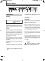
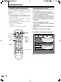
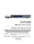
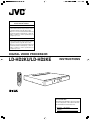
®
Machine Models Compatible for Connection with this Product
DLA-HD2KU
This product (LD-HD2KU) is exclusively for the
above-mentioned model. The performance cannot
be guaranteed when using with other models.
This processor is used as a dedicated machine and
this manual (instruction manual) may contain description of features as well as specifications not
used by the processor.
DLA-HD2KE
This product (LD-HD2KE) is exclusively for the
above-mentioned model. The performance cannot
be guaranteed when using with other models.
This processor is used as a dedicated machine and
this manual (instruction manual) may contain description of features as well as specifications not
used by the processor.
DIGITAL VIDEO PROCESSOR
LD-HD2KU/LD-HD2KE
INSTRUCTIONS
OFF
VIDEO
S-VIDEO
RGB
PASS-T
YCrCb
PASS-TX
MENU
PROFILE
STORE
1
2
3
4
5
6
7
8
9
0
BRIGHTNESS
COLOR
CONTRAST
TINT
ANAMORPHIC 4:3
DETAIL
LETTERBOX
®
For customer Use:
Enter below the Serial No. which is located
on the side panel of the cabinet. Retain
this information for future reference.
Model No. LD-HD2KU
Serial No.
LCT1679-001A
SAFETY PRECAUTIONS
IMPORTANT INFORMATION
IMPORTANT SAFEGUARDS
WARNING: TO PREVENT FIRE OR SHOCK HAZARDS, DO NOT EXPOSE THIS APPLIANCE TO RAIN
OR MOISTURE.
IMPROPER USE OF THIS EQUIPMENT CAN RESULT
IN POTENTIAL ELECTRICAL SHOCK OR FIRE HAZARD.
CAUTION:
To reduce the risk of electric shock, do not remove cover.
Refer servicing to qualified service personnel.
This product is equipped with a 3-blade grounding type plug
to satisfy UL, CUL, TUV, FCC rules.
If you are unable to insert the plug into the outlet, contact
your electrician.
FCC INFORMATION (U.S.A. ONLY)
CAUTION:
Changes or modifications not approved by JVC could void
the user’s authority to operate the equipment.
Note: This equipment has been tested and found to comply
with the limits for a Class B digital devices, pursuant to Part
15 of the FCC Rules. These limits are designed to provide
reasonable protection against harmful interference in a residential installation. This equipment generates, uses, and can
radiate radio frequency energy and, if not installed and used
in accordance with the instructions, may cause harmful interference to radio communications.
However, there is no guarantee that interference will not occur in a particular installation. If this equipment does cause
harmful interference to radio or television reception, which
can be determined by turning the equipment off and on, the
user is encourage to try to correct the interference by one or
more of the following measures:
– Reorient or relocate the receiving antenna.
– Increase the separation between the equipment.
– Connect the equipment into an outlet on a circuit different
from that to which the receiver is connected.
– Consult the dealer or an experienced radio/TV technician
for help.
About the installation place
Do not install the processor in a place that cannot support its
weight securely, or that does not allow for proper heat ventilation.
2
In order not to defeat the safeguards incorporated into this
product, observe the following basic rules for its installation,
use and service.
– All the safety and operating instructions should be read
before the product is operated.
– The safety and operating instructions should be followed
and retained for future reference.
– All warnings on the product and in the operating instructions should be adhered to.
– Unplug this product from the wall outlet before cleaning.
Do not use liquid cleaners or aerosol cleaners. Use a damp
cloth for cleaning.
– Do not use attachments not recommended by the product
manufacturer as they may be hazardous.
– Do not use this product near water. Do not use immediately after moving from a low temperature to high temperature, as this causes condensation, which may result in fire,
electric shock, or other hazards.
– Do not place this product on an unstable cart, stand, or
table. The product may fall, causing serious injury to a child
or adult, and serious damage to the product. The product
should be mounted according to the manufacturer’s instructions, and should use a mount recommended by the manufacturer.
– When the product is used on a cart, care should be taken
to avoid quick stops, excessive force, and uneven surfaces
which may cause the product and cart to overturn, damaging equipment or causing possible injury to the operator.
– Slots and openings in the cabinet are provided for ventilation. These ensure reliable operation of the product and
protect it from overheating. These openings must not be
blocked or covered. (The openings should never be blocked
by placing the product on bed, sofa, rug, or similar surface.
It should not be placed in a built-in installation such as a
bookcase or rack unless proper ventilation is provided and
the manufacturer’s instructions have been adhered to.)
– This product should be operated only with the type of power
source indicated on the label. If you are not sure of the
type of power supply to your home, consult your product
dealer or local power company.
– This product is equipped with a three-wire plug.
This plug will fit only into a grounded power outlet. If you
are unable to insert the plug into the outlet, contact your
electrician to install the proper outlet. Do not defeat the
safety purpose of the grounded plug.
– Power-supply cords should be routed so that they are not
likely to be walked on or pinched by items placed upon or
against them. Pay particular attention to cords at doors,
plugs, receptacles, and the point where they exit from the
product.
– For added protection of this product during a lightning storm,
or when it is left unattended and unused for long periods of
time, unplug it from the wall outlet and disconnect the cable
system. This will prevent damage to the product due to lightning and power line surges.
– Do not overload wall outlets, extension cords, or convenience receptacles on other equipment as this can result
in a risk of fire or electric shock.
– Never push objects of any kind into this product through
openings as they may touch dangerous voltage points or
short out parts that could result in a fire or electric shock.
Never spill liquid of any kind on the product.
– Do not attempt to service this product yourself as opening
or removing covers may expose you to dangerous voltages
and other hazards. Refer all service to qualified service
personnel.
– Unplug this product from the wall outlet and refer service
to qualified service personnel under the following conditions:
a) When the power supply cord or plug is damaged.
b) If liquid has been spilled, or objects have fallen on the
product.
c) If the product has been exposed to rain or water.
d) If the product does not operate normally by following
the operating instructions. Adjust only those controls that
are covered by the Operation Manual, as an improper
adjustment of controls may result in damage and will
often require extensive work by a qualified technician to
restore the product to normal operation.
e) If the product has been dropped or damaged in any
way.
f ) When the product exhibits a distinct change in performance – this indicates a need for service.
– When replacement parts are required, be sure the service
technician has used replacement parts specified by the
manufacturer or with same characteristics as the original
part. Unauthorized substitutions may result in fire, electric
shock, or other hazards.
– Upon completion of any service or repairs to this product,
ask the service technician to perform safety checks to determine that the product is in proper operating condition.
– The product should be placed more than one foot away
from heat sources such as radiators, heat registers, stoves,
and other products (including amplifiers) that produce heat.
– When connecting other products such as VCR’s, and personal computers, you should turn off the power of this product for protection against electric shock.
– Use only the accessory cord designed for this product to
prevent shock.
*DO NOT allow any unqualified person to install the
unit.
Be sure to ask your dealer to install the unit since special
technical knowledge and skills are required for installation
and connection to multiple devices.
If installation is performed by an unqualified person, it may
cause personal injury or electrical shock.
Precautions for using the screen terminal
Connect the cable to the screen before using the screen terminal of this unit.
Signal with DC+12 V/100 mA max. is output from the screen
terminal of this unit.
Short-circuit will result in malfunction, fire and electric shock.
Leave the connection of the wires to the installation contractor.
The power supply voltage rating of this product is AC 120 V,
AC 100 V - AC 240 V, the power cord attached conforms to
the following power supply voltage. Use only the power cord
designated by our dealer to ensure Safety and EMC. When it
is used by other power supply voltage, power cable must be
changed.
Ensure that the power cable used for the projector is the correct type for the AC outlet in your country.
Consult your product dealer.
3
TABLE OF CONTENTS
SAFETY PRECAUTIONS ............................................................................................................................................... 2
QUICK START ................................................................................................................................................................ 5
INSTALLATION ............................................................................................................................................................... 6
SETUP ............................................................................................................................................................................ 8
IR REMOTE/OSD ......................................................................................................................................................... 10
RS232 ........................................................................................................................................................................... 13
HELP MENUS ............................................................................................................................................................... 16
SPECIFICATIONS ......................................................................................................................................................... 17
4
QUICK START
Connection with Other Devices
Before connecting to other devices, ensure to turn off the power supply of the device to be connected with the digital video
processor.
䡵 Connecting to a Projector
● Read through the projector’s instruction manual thoroughly.
● Depending on the DVI cable used, signals may be attenuated and images may become unstable. Use high-quality DVI
cables that are 5 m or shorter. When a DVI cable longer than 5 m is used, make use of a distribution system or an optical
fiber cable.
Right End of this Unit
H/C SYNC
UTPUT
V SYNC
I/R REMOTE
SCREEN
DVI INPUT
RS-232
DVI OUTPUT
100-240 VAC
50-60Hz 35 WATTS
DVI
VIDEO IN
DVI Connection Cable (sold separately)
Caution on Devices to be Connected
Please refer to the list of ‘Devices Compatible with this Product’ on the front page for devices that can be
connected with this unit. Performance of this unit will not be guaranteed if it is connected with a device not
specified in the list.
Setup of this Unit
1. Connect the supplied power cord to the power supply input terminal on this unit. Connect the earth wire to the
equipped earth terminal in the building, followed by inserting the plug of the supplied power cord into the wall
outlet.
2. This unit will be initialized once the plug of the power cord
is inserted into the power outlet. Upon completion of initialization, this unit switches to the Standby mode (LED
turns red).
3. Press the Power/Standby button on this unit (or Power
button on the remote). Once the unit is turned on, the
LED turns green.
4. Press the Menu button on the remote for 5 seconds or
more to display the Setup Menu on this unit’s display
panel. After the Setup Menu is displayed, use the Function Up/Down keys on the remote to select an adjustment.
Select the set values accordingly using the Value Left/
Right keys on the remote.
5. Select Set: SCANRATE and set the value to 1920 x 1080.
Press the STORE key on the remote. The message “Are
You Sure” is displayed on the display panel of this unit.
Press the STORE key on the remote again to set the scan
rate.
6. Select Set: Active Output and set the value to Digital.
7. Select Set: Screen Shape and set the value to Wide Screen.
8. Press the Menu button on the remote to exit the Setup
Menu.
Profile Setting
This unit can store up to 8 profiles. Each profile stores values
that have been set for this unit during each adjustment. Select
the profile number (1 - 8) at the OSD and press the STORE
key on the remote to save the current settings. For further
details, please refer to ‘OSD’. (☞ Page 10)
Video Image Adjustment
The following item can be adjusted according to the input
signals. Adjusted values can also be stored in the profile.
●
●
●
●
●
●
BRIGHTNESS (☞ Page 11)
CONTRAST (☞ Page 11)
COLOR (☞ Page 12)
TINT (☞ Page 12)
DETAIL (☞ Page 12)
ADVANCED COLOR SYSTEM (☞ Page 12)
5
INSTALLATION
3
8
9 p
q
OUTPUT
INPUT
Y/C
VIDEO
RED/Pr
GREEN/Y
12
RED/Pr
BLUE/Pb
C-SYNC
GREEN/Y
BLUE/Pb
I/R REMOTE
SCREEN
MONITOR OUTPUT
DVI INPUT
4
5
6
Accessories
The following accessories are packed together with this unit.
Please confirm all items. If any item is missing, please contact
your dealer.
• Remote Control
• AA/R6 size Battery
(for operation confirmation)
• Guarantee
Placement
The processor can be either placed on a table or rack
mounted. A rack mounting installation kit is available. Securely
mount the side rack brackets with the screws that are provided
with the kit.
Ventilation
The unit uses convection to cool. A fan is not needed. As hot
air raises out of the top vent, cool air is drawn in from the
bottom and side. These vents must not be blocked. When
rack mounted, a minimum of 1.75” (1 rack unit height) of free
space is required above and below the unit to allow for proper
cooling. A forced air fan should be added to the rack
installation if power amps are located in the same air space.
Do not install unit above power amps.
Connections
Because of the high performance of this unit it is very important
to use the highest quality cables possible, for both input and
output signals.
To avoid AC ground loop problems, the source equipment,
this unit and projector should all be running on the same
grounded AC power line (one rated for the power
requirements).
1 S-Video input (4-pin DIN) for sources such as DVDs,
Satellite systems, S-VHS tape decks (when using S-VHS
tapes only), Hi-8 tape decks.
2 Composite video input (BNC) for sources such as
Laserdisc players, cable TV, VHS tape decks, 8mm tape
decks.
6
V SYNC
HDTV INPUT
INSTALLATION
• Instructions
• Power Cord
H/C SYNC
RS-232
DVI OUTPUT
7
100-240 VAC
50-60Hz 35 WATTS
w
3 YPrPb/RGBs Input (BNC): 480i and HDTV scan rates are
sent to the internal processor and then output at the selected scan rate. If the output is set to analog RGBHV or
digital DVI, the unit will automatically transcode the YPrPb
HDTV to RGBHV.
Note on DVDs:
For proper aspect ratio and to insure the highest quality
image from the DVD player, be sure to set the DVD screen
shape to 16:9 in the DVD player’s Setup menu. See the
DVD player’s owner’s manual for details.
4 High scan rate input (D-sub15 pin) for sources such as
HDTV signals or computers are passed through to the
projector. The signal is sent to the outputs in the same
format as the input unless Transcoding is selected. YPrPb
from HDTV sources can be transcoded to RGBHV, as
well. Use a BNC to D15 breakout cable if necessary. The
Green, Red, Blue BNCs are used for YPrPb.
5 D-sub15 pin connector output for use with computer monitors or to a second display device. Use only short cable
runs. This output can be used at the same time as the
BNC outputs.
6 DVI Input. The DVI Input will automatically process 480p,
720p and 1080p signals. Computer rates are not supported for processing but may be passed through to the
DVI output if any of the pass-through inputs are selected.
This unit will not convert a computer DVI output to the
analog output.
Note
For incompatible input signals, a “Not Supported”
message will be displayed on the LCD display
and the image will be muted (black screen).
Installation (continued)
7 DVI Output: Digital output interface for compatible displays. All processed analog and digital inputs are output to this connector as well as
computer scan rates when the pass-through
input is selected. Maximum cable length is
50ft with a high quality DVI cable. For longer
lengths a distribution system or fiber optic
system must be used.
8 BNC connectors for main output with RGBHV or YPrPb
signals to display devices. Cable runs up to 100ft are okay
if good quality cables are used. For YPrPb outputs use:
Red
= Pr
Green
=Y
Blue
= Pb
RGBHV is recommended.
● If Computer signals are to be used, separate H & V
sync cables must be connected to the display.
9 IR remote terminal
The following diagram offers one way to connect the system.
Satellite Receiver
YPrPb
S-Video HDTV
DVI
Alt.
Conn.
S-Video HD/PC YPrPb
Input
Input Input
DVI
Input
This unit
RGBVH
DVI
Set Input to Transcode
Display
With this hookup viewing the different sources is as follows:
USE THIS
UNIT’S
INPUT
USE THIS UNIT’S
OUTPUT
Non-HDTV Channels
S-Video
RGBHV or DVI
Native HDTV Channels
DVI
DVI or RGBHV
Native HDTV Channels
YPrPb
DVI or RGBHV
Native HDTV Channels
with HDCP Encryption
YPrPb
RGBHV
SOURCE
Cannot be used with this digital video processor.
p SCREEN terminal
12V trigger to activate automatic screen relays. Voltage
is constant when unit power is on.
In addition, refer to ‘Precautions for using the screen terminal’ on page 3 before using it.
q RS-232C (D-sub 9 pin) terminal
RS-232C connection for use with RS-232C control systems.
w AC Power connection.
● This unit’s pass-through input will “pass ” the input signal
to the output stage in the same format as the input
signal, i.e. analog HDTV in – analog HDTV out, DVI
HDTV in – DVI HDTV out.
Note
● The DVI or analog RGBHV outputs cannot be active at
the same time. Select the output type in the
Setup menu prior to use of the processor.
Connecting HDTV Satellite Receivers
Since HDTV ready satellite receivers offer different signal
types, they require special attention for connection to the
processor. Every receiver is different so be sure to consult
the receivers manual for details. For this manual, we will
assume the receiver being used operates as follows:
1. Non HDTV material is output from the receiver via an Svideo connection
2. HDTV material is output via YPrPb outputs
3. If available, HDTV material is also output via a DVI connector.
HDTV Cross-Conversion
This unit can cross-convert 480p, 720p and 1080i HDTV
signals to the selected output of the processor. Any HDTV
signal connected to the YprPb BNC or DVI inputs will be
cross-converted. Any HDTV or PC signal connected to
the D15 input will be passed-through without processing.
PC signals via the DVI input will be sent to the passthrough.
To pass-through HDTV signals to avoid processing, select
the passthrough input. DVI is passed through
to the DVI output and analog YPrPb is passed through as
analog RGB (select trancode).
7
SETUP
POWER
1 2 3
FRONT PANEL CONTROL
1 Firmware Reset:
Push a small paper clip into this opening to reset the unit’s
CPU.
● Use this reset only if the unit will not respond to commands.
It will not erase custom settings. Use the Factory Restore
command in the Setup Menu to completely reset firmware.
See the setup section of the manual for details.
2 Power / Standby:
Press to turn the unit On (LED turns Green) or to Standby
(Red).
3 Infrared Receiver Window
4
SETUP MENU FUNCTIONS
SET : SCANRATE
Select the required scanrate by using the right and left arrows.
When the desired rate is displayed on the LCD display, press
the STORE key. This unit will ask you “Are you sure” and
press the STORE key again. The scanrate is now selected.
SET : ACTIVE OUTPUT
Analog / Digital (Default)
This must be selected to determine if the Analog (BNC) or
Digital (DVI) output is used. Both outputs cannot be used at
the same time.
4 LCD Readout:
Provides information on control of the processor. Displays
current Function being used, matching the On-ScreenDisplay. When in the Setup Menu, the OSD is not available, use the LCD display.
SYSTEM FIRMWARE SETUP
Now that all the sources and cables are connected, the
processor’s firmware needs to be setup for the installation.
Be sure to go through the Setup menu before doing the
final setup of the display.
When the unit is first plugged in it will go through an initializing
procedure and display the output resolution. Do not send any
commands to the unit during this initialization period. Once
this initialization is completed the unit is instant-on.
Note
All display devices have specific setup steps that
must be completed to insure proper operation
with this unit and other sources. Be sure to
carefully follow those instructions as well as the
instructions for this processor.
To enter the Setup menu, press and hold the Menu
button on the remote for five seconds. Setup Functions can only be viewed on the front panel LCD, not
from the OSD.
Press the Function Up or Down to select the available
Functions. Press the Value Up or Down keys to change values
or to select options.
8
SET : SCREEN SHAPE
Wide Screen / 4:3 / Wide 4:3
● This sets the processor for the screen shape of the display
to be used. If this is not set properly, the aspect ratio selection for the different sources located in the user menu will
be incorrect.
䡵 WIDE SCREEN
Choose this when the screen is Widescreen and the projector will provide the anamorphic vertical squeeze.
Example : Example: A 16:9 plasma, a digital or CRT
projector set to Anamorphic using a wide angle
screen or when using a Panamorph lens, or a
1280x720 digital projector.
䡵 4:3
Choose this when the projector is 4:3 and the screen is
4:3
Example : Using a 1024x768 digital projector on a 4:3
screen.
䡵 WIDE 4:3
Choose this when the digital projector operates as 4:3
and the screen is Widescreen. (Not available on units
scanning at rates below 720p.)
Example : A digital projector that has a 4:3 display chip
that locks the aspect ratio when sent the native
resolution and then displayed on a wide angle
screen.
Setup (continued)
SET : BLACK LEVEL (For setting the black level)
SET : PASSTHRU TRANSCODE
7.5 IRE / 0 IRE (Default)
For setting the black signal level of the video signal. When
the video signal is “7.5 IRE Setup”, set to “7.5 IRE”.
Disable (Default) / Enable
YPrPb HDTV signals via the D15 input or the YprPb (BNC)
inputs can be transcoded to RGB when this feature is enabled.
SET : DVI Input Level (For setting the gray scale)
SET : COMPONENT INPUT STANDARD
16-235 / 0-255 (Default)
DVD (Default) / Professional (Betacam)
● Only use professional setting when using a device that
conforms to SMTPE Betacam levels
OUTPUT FORMAT (ANALOG)
RGB (Default) / YPrPb
Selecting RGB means connecting the processor to the display
via five wire analog RGBHV. This function is not active when
DVI output is selected. DVI is always RGBHV.
SET : RGB INPUT SYNC
Sync-on-Green (Default) /Composite Sync
SET : DVI INPUT H SYNC (For setting the H Sync)
COMPOSITE SYNC ON H
On / Off (Default)
● This function is not active when YPrPb output is selected.
● Each input on this unit can be activated or deactivated to
simplify operation so unused inputs are not accessed when
cycling through the inputs with the remote control.
Normal (Default) / Wide
SET : OSD (ON SCREEN DISPLAY)
On (Default) / Off
SET : OSD TIMER
0-255 (30 Default)
SET : VIDEO INPUT
Enabled (Default) / Disabled
● Disabling this unused input will remove it from the input
menu list.
SET : S-VIDEO INPUT
Enabled (Default) / Disabled
● Disabling this unused input will remove it from the input
menu list.
SET : LCD TIMER
6-255 (40 Default)
● Setting value below 5 will not be displayed. “ALWAYS ON”
is displayed on the LCD display and the backlight is always lit.
SET : RS232 ECHO
On (Default) / Off
Allows RSR232 characters to be sent back to the controller.
SET : RGB INPUT
Enabled (Default) / Disabled
● Disabling this unused input will remove it from the input
menu list.
SET : BAUD RATE (For setting the baud rate of
RS-232C)
SET : Y/Pr/Pb INPUT
SET : Store NTSC profiles 1-8
Enabled (Default) / Disabled
● Disabling this unused input will remove it from the input
menu list.
SET : Store PAL profiles 1-8
19200 (Default) / 57600 / 9600
SET : RESTORE FACTORY
SET : DVI INPUT
Enable / Disable
● Disabling this unused input will remove it from the input
menu list.
SET : PASSTHRU INPUT
Enabled (Default) / Disabled
● Disabling this unused input will remove it from the input
menu list.
Are You Sure? - Press Enter Key
Use this Function only in the event that the processor
no longer functions properly and all other system checks
have been performed. This command will erase all
custom settings and restore the original firmware
configuration. Be sure to go back through the Setup
procedure for proper operation.
Note
The next step in the setup procedure is to align the
display device. Be sure to follow all directions for
setting up the display found in the display’s manual.
Using a test DVD with the Safe Area test pattern,
align the image size, position and blanking first
using the controls found in the display device.
Only use these controls in this unit if the display
device does not offer these controls or if there is
not enough range.
9
IR REMOTE/OSD
IR REMOTE AND OSD OPERATION
This unit is now shipped with a simplified remote control that
allows for direct access to most commands used to control
the processor.
Adjustments can be made three different ways:
1. Press the Menu button to activate the OSD and use the
Function and Value keys to make changes. Press Menu
again to remove OSD.
2. Press the direct access key (Brightness, etc.) and then
adjust using the left/right value keys.
3. Press the direct access key and then enter a three digit
number (i.e. 040 for 40).
ON SCREEN DISPLAY (OSD)
Accessing the OSD
1. Press Menu button to bring up main Index.
2. Use Function Up/Down Keys until the triangle
at the top of the OSD turns yellow.
3. Use the Left/Right keys to move to the next menu
page. A list of available Functions will appear.
4. Press Function Up/Down keys to select an
adjustment.
5. Use Value Left/Right keys to adjust.
The main menu drops away and a single line
menu appears.
4. For direct access to the RGB input:
Press DVI + 1
(allow about one second between commands)
6. Use the Function keys to return to the drop down
menu.
7. Press Menu at any time to cancel OSD
Turn unit
On/Off
OFF
Select Inputs
VIDEO
S-VIDEO
DVD button
not active
DVI/RGB
YCrCb
PASS/TX
DVD
MENU
Navigate
Menus
PROFILE
Enter
Numbers
STORE
1
2
3
4
5
6
7
8
9
● Unused inputs can be deactivated for simpler operation of
the processor. See the Setup instructions for details.
INPUT
Press to
toggle
between
passthrough and
passthrough
transcode
CONTRAST
ASPECT
ANAMORPHIC
Use the Value Left/Right
keys to change selection
or values.
TINT
ANAMORPHIC 4:3
10
DETAIL
LETTERBOX
F 1 2 3 4
Adjust Picture
STORE
COLOR
PATTERNS
INPUTS
RECALL
BRIGHTNESS
DISPLAY
Press the Function UP/Down
keys until the triangle turns Yellow.
Press the Value Left/Right keys to
cycle to the Menu tabs.
DVD
FORMATS
PROFILE
0
PICTURE
The OSD consists of four menu tabs:
Input - Picture - Display - Patterns
1 2 3 4
䡵 Input Menu
INPUT
PICTURE
PATTERNS
DISPLAY
● When using a 4:3 source on a Wide Angle screen there
are black bars on the left and right of the image. The
sidebars can be changed to gray using the Blanking Level
control located in the Display menu. If filling the entire screen
is desired, select Letterbox. The image will fill the screen
but the top and bottom 1/3 of the image will be cut off
(overscanned).
FORMATS
INPUTS
ASPECT
DVI
ANAMORPHIC
PROFILE
RECALL
When watching 2:35 aspect ratio movies on a 16:9 (1:77)
screen, it is normal to see black bars at the top and bottom
of the image.
F 1 2 3 4
STORE
● The screen shape used in the installation must be set in
the Setup Menu during installation for proper Aspect Ratio
mapping. Anamorphic Aspect Ratio with 4:3 screens and
the Wide-4:3 settings are not available on units with scan
rates, 540p, 600p and Frame Doubling. See Setup section
for details.
1 2 3 4
Note
Do not leave the 4:3 image with a Wide Angle
screen on for long periods of time on a
projector or plasma display. This can cause
permanent image burn-in. Image burn-in is
not covered by warranty
Formats
1. Input Select: OSD
Video-S-Video- RGB-YCrCb-DVI
● The Pass-Thru input cannot be selected from the OSD
since an OSD is not available on that input. Use the
Input button on the remote to select it. The DVI Input
will not display an OSD unless there is a source connected to it.
2. Aspect Ratio
4:3-Letterbox-Anamorphic
● This selection should match the aspect ratio of the
source, not the display. The aspect ratio of the display
should be selected in the Setup menu.
䡵 Picture Menu
Use these commands to fine-tune the image.
● After tuning the image, if the power is turned off without
storing the profile, the factory default value will be restored.
INPUT
PICTURE
DISPLAY
PATTERNS
Profiles
1. Profile: Factory-1-2-3-4-5-6-7-8
BRIGHTNESS
50
CONTRAST
50
COLOR
50
TINT
50
2. Store: 1-2-3-4-5-6-7-8
To store a Profile (in the Input Menu):
1. Press Menu button on the remote
2. Make all required adjustments.
3. Use the Function Up/down keys to select Profile
4. Use the Value Left/Right keys to select Profile
DETAIL
4
5. Press Enter
ADVANCED COLOR SYS
NORMAL
To recall a Profile (in the Input menu):
1. Press Menu button on the remote
Brightness
2. Use the Function Up/Down keys to select Recall
Factory 50
Adjust the brightness of the picture image.
3. Use the Value Left/Right keys to select profile
1-8
4. Press Store
5. There are separate banks of eight Profiles for
NTSC and PAL
Contrast
Factory 50
Adjusts the contrast of the picture image.
11
Osd (continued)
Color
Factory 50
Adjust the color density of the picture image.
䡵 Display Menu
INPUT
PICTURE
DISPLAY
PATTERNS
Tint
Factory 50
Tint is not available with YPrPb or PAL sources
POSITION
HORIZONTAL
25
VERTICAL
25
BORDER LVL
0
LEFT
RIGHT
BOTTOM
TOP
Detail
Factory 4
● The Detail circuit is a powerful tool for image quality. The
settings have been optimized for the output scan rate and
resolution. However, the viewer’s tastes plus the types of
software and display require making adjustments of this
setting to fine-tune the image. This control is very effective
to increase detail in poor quality video material. It is recommended that adjustments be made in small increments
until the desired results are achieved and then store these
custom settings in the Profiles. It is important to not use
too much Detail since the image will start to look artificial.
Typically, digital displays will need less detail than analog
displays. High quality software will need less detail than
poor quality ones. Reducing the Detail level can help to
reduce the visibility of MPEG artifacts on some DVDs and
satellite systems and noise with VHS tapes. The best results are achieved by adjusting the levels to the software
being viewed instead of just using test patterns.
Use these commands to adjust the image position and edge
blanking. It is recommended to adjust sizing, position and
blanking in the display device first with this unit in the Factory
preset setting. Then use this unit’s controls only if the display
runs out of range or does not offer these controls. This should
be done by a qualified technician.
Horizontal Position
Not functional on this unit.
Advanced Color System
Normal (Default) / Bypass
For some DVDs with computer animation or with very high
levels of color, the chroma edge processing circuits may not
be needed and can be turned off (Bypass). For most sources,
the Normal setting should be selected. These settings can
be stored as a Profile.
● Any changes to the picture level adjustments are automatically stored after one minute has passed without making
any changes. This information is stored separately for each
input. As each input is selected the last used settings will
automatically be recalled. If picture levels are adjusted but
then the input is changed before one minute has passed,
the changes for that input will not be stored and the previous settings will be recalled the next time that input is used.
Vertical Position
Not functional on this unit.
Border LVL (Blanking level)
Setting Values: 0-100
This adjusts the blanking from black to white. This can be
used to create a gray side bar for use with 4:3 aspect ratio
sources on wideangle screens to help reduce the chance of
image burn-in. Image burn in is not covered by warrantee.
Left
Adjusts the left edge border (blanking).
Right
Adjusts the right edge border (blanking).
Bottom
This adjusts the bottom edge border (blanking).
Top
Adjusts the top edge border (blanking).
● This unit will store unique blanking settings for each aspect ratio which are automatically stored and recalled when
the different aspect ratios are selected
12
RS232
䡵 Patterns Menu
The best approach to system setup is to use a DVD that
offers the proper test patterns. This way, the system is
aligned for the entire signal path. If a test DVD is not available, then use the internal test patterns provided in this
unit.
● The test pattern generator in this unit is set to SMPTE standards. To insure proper output levels for display setup, the
picture controls in this unit cannot be accessed when the
test patterns are being used. Adjust levels, if needed, in
the display device.
INPUT
PICTURE
DISPLAY
PATTERNS
AVAILABLE PATTERNS
Gray Step
Cb Ramp
Cr Ramp
Y Ramp
Black
Green Screen
Red Screen
Blue Screen
Convergence
Border
Multiburst
Window
PLUGE
Color Bars
Rev Bars
:
:
:
:
:
:
:
:
:
:
:
:
:
:
:
Check gray scale
Check linearity of Cb channel
Check linearity of Cr channel
Check linearity of Y channel
Full Black screen
Check for defective pixels
Check for defective pixels
Check for defective pixels
Check convergence of display
Use for H&V positioning
To check bandwidth
Check displays power supply
Set Brightness and Contrast
Color bars for decoder check
Color bars for decoder check
RS232 INSTRUCTIONS
Connector
Baud rate
Pin Configuration
TEST PATTERNS
SELECT
ON
CONVERGENCE
: DB-9 Female
: 19,200 default, 8 bit,1 stop bit and
No Parity
: Pin 5=Ground
Pin 3=RX in
Pin 2=TX out
All commands are sent using ASCII text strings.
● A command must start with the string header
13
RS232 (continued)
Following the header, a comma is used to delimit the header from the command. All the commands with their descriptions are
listed below. All the text strings are terminated with a carriage return (0x0d or 13). Maximum command string length is 250
characters.
OPERATION COMMANDS (Used for day-to-day operation)
DESCRIPTION
OPTIONS OR RANGE
COMMAND
A#
(0-2) 0=4x3,1=Letterbox, 2=Anamorphic
Input Aspect Ratio – for all sources
B#
(0-170) 128 default
Brightness
C#
(0-155) 110 default
Contrast
D#
(0-13) 8 default
Detail
DVI
DVI Input
EXT
Pass-through Input
FST
Report Current System Status
Displays full list of commands for this unit
HELP
K#
(0-220) 128 default
Color
OFF
Power OFF
ON
Power ON
P#
(0-8) [1-8=User, 0=Factory]
Recall Preset
PM#
(0-1) [0=Normal1=Bypass]
Advanced Color System
PassThru Transcoded Input
PY
R
RGB input
ST
Report Current Status
T#
TP#
(0-255) 128 default
Tint
0=Off
1=100% Color Bars
2=Reverse Color Bars
3=10-step Grayscale
4=Luma Ramp
5=Cb Ramp
6=Cr Ramp
7=Green
8=Red
9=Blue
10=Convergence
11=Active Boarder
12=Multiburst
13=100% Window
14=PLUGE Test Pattern Selection
TPHELP
14
Display Test Pattern Help
V
Video input
X
YCrCb input
Y
S-Video input
SETUP COMMANDS (Normally not controlled by RS232)
OPTIONS OR RANGE
COMMAND
DESCRIPTION
BB#
(0-192)
Bottom Blanking
BL#
(0-252)
Border Level – black to white
BLT#
(0-255)
LCD Backlite Timer on front panel
CS#
1=On 0=OFF
Composite Sync – for RGB output
DVI Input Disabled
DVD
DVI Input Enabler
DVE
1=On 0=OFF
E#
RS-232 ECHO
PassThru Input Disabled
EXTD
PassThru Input Enabled
EXTE
HP#
(0-50) 25 default
Horizontal Position
LB#
(0-200)
Left Blanking
M#
(0-1) [0=RGB, 1=YPrPb]
Output Mode
OSD Off – for processor
OSDOFF
OSD On – for processor
OSDON
OUTMOD
0=Analog, 1=Digital
PassThru Transcode Disable
PYD
Pass-Thru Transcoder Enabled
PYE
RB#
Output Mode
000-192
Right Blanking
RD
RGB Input Disabled
RE
RGB Input Enabled
Restore Factory Defaults
SETFT
STPP#
1-8
Store PAL Profile
STNP#
1-8
Store NTSC Profile
Scan Rate Help Table
SRHELP
TB#
000-192
Top Blanking
VD
Video Input Disabled
VE
Video Input Enabled
VPOL#
W#
(0=Neg 1=Pos)
Vsync Polarity
0=4:3, 1=Widescreen, 2=Wide 4:3
Screen Shape
XD
YCrCb Input Disabled
XE
YCrCb Input Enabled
YD
S-Video Input Disabled
YE
S-Video Input Enabled
NTSC SCAN RATE LIST (USE ONLY BY QUALIFIED TECHNICIAN!)
SRN2
1920 x 540
SRN3
800 x 600
SRN4
1280 x 720
SRN5
1024 x 768
SRN6
1280 x 768
SRN7
1366 x 768
SRN8
1440 x 960
SRN9
1280 X 1024
SRN10
D-ILA
SRN11
1400 x 1050
SRN12
1920 x 1080
PAL SCAN RATE LIST (USE ONLY BY QUALIFIED TECHNICIAN!)
SRP1
SRP2
720x576/50Hz
SRP3
1024x768/75Hz
1280x720/50Hz
SRP4
1920x1080/50Hz
15
HELP MENUS
TEST PATTERN HELP MENU
TP0
TEST PATTERN OFF
TP1
100% COLOR BARS
TP2
REVERSE COLOR BARS
TP3
10 STEP GREY
TP4
LUMA RAMP
TP5
CB RAMP
TP6
CR RAMP
TP7
BLACK SCREEN
TP8
GREEN SCREEN
TP9
RED SCREEN
TP10
BLUE SCREEN
TP11
CONVERGENCE
TP12
ACTIVE BORDER
TP13
SMPTE PATTERN
TP14
WHITE WINDOW
TP15
PLUGE
Output Scan Rate
16
Horizontal Frequency
Vertical Frequency
1920 x 540P
33.8 KHz
59.94 Hz
720 x 576P
31.3 KHz
50.00 Hz
800 x 600P
37.6 KHz
59.94 Hz
1280 x 720P
45.0 KHz
59.94 Hz
1280 x 720P
37.5 KHz
50.00 Hz
1024 x 768P
60.5 KHz
75.00 Hz
1024 x 768P
48.3 KHz
59.94 Hz
1366 x 768P
48.3 KHz
59.94 Hz
1440 x 960P
62.9 KHz
59.94 Hz
1280 x 1024P
63.9 KHz
59.94 Hz
1365 x 1024P
63.5 KHz
59.94 Hz
1400 x 1050P
64.0 KHz
59.94 Hz
1920 x 1080P
56.3 KHz
50.00 Hz
1920 x 1080P
67.4 KHz
59.94 Hz
SPECIFICATIONS
䡵 Model Name/ Article Name
LD-HD2KU/LD-HD2KE Digital Video Processor
䡵 Colour System
NTSC, PAL (Auto switching)
䡵 Video Input
Signal
Horizontal Frequency
Vertical Frequency
480i
15.7 KHz
29.97 Hz
480p
31.5 KHz
59.97 Hz
576i
15.6 KHz
25.00 Hz
576p
31.3 KHz
50.00 Hz
720p
37.5 KHz
50.00 Hz
720p
45.0 KHz
59.97 Hz
1080i
28.1 KHz
25.00 Hz
1080i
33.7 KHz
29.97 Hz
䡵 Input Terminals
VIDEO
1-line, BNC x 1
Y/C
1-line, mini-DIN 4 pin x 1
R,G,B,C-SYNC
1-line, BNC x 4
R,G,B: 0.7 Vp-p
Y, Pr, Pb
1-line, BNC x 3
Y: 1.0 Vp-p
DVI
1-line, DVI-D 24 pin , HDCP-compatible
HDTV
1-line, D-sub 15 pin
1.0 Vp-p
Y: 1.0 Vp-p, C: 0.286 Vp-p
C-SYNC: 1.0 Vp-p
Pr, Pb: 0.7 Vp-p
Pin No. Signal Name Pin No. Signal Name
RS-232
Pin No. Signal Name
1
Red, Pr
6
GND
11
–
2
Green, Y
7
GND
12
–
3
Blue, Pb
8
GND
13
H-sync
4
–
9
–
14
V-sync
5
GND
10
GND
15
–
1-line, D-sub 9 pin, RS-232C (External control)
䡵 Output Terminals
R,G,B,H/C-SYNC,V
1-line, BNC x 5
R,G,B: 0.7 Vp-p/75 ¸, H/C-SYNC, V: 4.5 V/2 K¸
Y, Pr, Pb
1-line, BNC x 3
Y: 1.0 Vp-p, Pr, Pb: 0.7 Vp-p
MONITOR
1-line, D-sub 15 pin
R,G,B,Pr, Pb: 0.7 Vp-p/75 ¸, Y: 1.0 Vp-p, H, V : 4.5 V/2 K¸
DVI
1-line, DVI-D 24 pin, HDCP-compatible
SCREEN
1-line, mini-jack (+12 VDC Screen trigger, 100mA) (Tip=V+, Case=GND)
䡵 Power Requirements
AC 100 V - 240 V, 50 Hz/60 Hz, Power consumption 1.0 A
䡵 Operation Environment
Temperature
41°F to 95°F (+5 °C to +35 °C)
Humidity
20% to 80% (No condensation)
Storage Temperature 14°F to 140°F (–10 °C to +60 °C)
䡵 Dimensions
(Width x Height x Depth)
Approx. 1 3/4" x approx. 17 " x approx. 11 4/5" (Approx. 45 mm x 438 mm x 303 mm)
(Excluding carrying handle, lens and protrusion portion)
䡵 Mass
Approx. 13.9 lbs (Approx. 6.3 kg)
䡵 Accessories
(☞ Page 6)
● Design and specifications are subject to change without prior notice.
● Please note that some of the pictures and illustrations may have been abridged, enlarged or contextualized in order to aid
comprehension. Images may differ from the actual product.
17
MEMO
.........................................................................................................................
.........................................................................................................................
.........................................................................................................................
.........................................................................................................................
.........................................................................................................................
.........................................................................................................................
.........................................................................................................................
.........................................................................................................................
.........................................................................................................................
.........................................................................................................................
.........................................................................................................................
.........................................................................................................................
.........................................................................................................................
.........................................................................................................................
.........................................................................................................................
.........................................................................................................................
.........................................................................................................................
.........................................................................................................................
.........................................................................................................................
.........................................................................................................................
.........................................................................................................................
.........................................................................................................................
.........................................................................................................................
.........................................................................................................................
.........................................................................................................................
.........................................................................................................................
18
LD-HD2KU/LD-HD2KE
DIGITAL VIDEO PROCESSOR
®
VICTOR COMPANY OF JAPAN, LIMITED
© 2004 VICTOR COMPANY OF JAPAN, LIMITED
Printed in Japan
0504-SW-VP