1
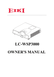
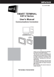
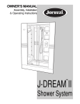
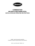
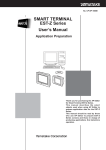
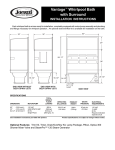
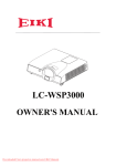
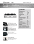
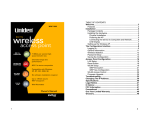
SUMMER RAIN™ II
2 PERSON SHOWER SYSTEM
TWO WALL AND THREE WALL
INSTALLATION AND OPERATING INSTRUCTIONS
Jacuzzi Whirlpool Bath© BZ00000 03/05
IMPORTANT SAFETY INFORMATION
Do not place or use electrically connected devices, such as television, radio, or stereo speakers, lights, hair
dryers, or telephones, within 1.5 m (5 feet) of shower.
Note: This is a professional grade product. A knowledge of construction techniques, plumbing and electrical
installation according to codes are required for proper installation and user satisfaction. We recommend that
a licensed contractor perform the installation of all Jacuzzi Whirlpool Bath© products. Our warranty does not
cover improper installation related problems.
CONTENTS
Specifications _________________________________________________________________________ 2
Enclosure Specifications ________________________________________________________________ 3
Rough-in Reference ____________________________________________________________________ 3
Component Identification ________________________________________________________________ 4
Base Installation ______________________________________________________________________ 5-6
Clean Up After Base Installation __________________________________________________________ 7
Towers and Doors Installation _____________________________________________________________ 8-17
Clean Up After Towers and Doors Installation ________________________________________________ 17
Operation
___________________________________________________________________________ 18-19
Maintenance __________________________________________________________________________ 20
Tower Fixture Repair Parts _______________________________________________________________ 21
Tower Plumbing Repair Parts _____________________________________________________________ 22
Warranty ____________________________________________________________________________ 25-26
Save These Instructions for Future Use.
Owner's Record
Date Purchased ____________________________________________________________
Purchased From ____________________________________________________________
Installed By ________________________________________________________________
Serial Number _____________________________________________________________
Model ____________________________________________________________________
1
Jacuzzi Whirlpool Bath© BZ00000
03/05
SPECIFICATIONS
Important: Read complete instructions before beginning installation.
Each unit arrives ready for installation, equipped with base, glass and associated hardware.
Remove the unit from the carton. Retain the shipping carton until satisfactory inspection of the product has been
made.
Immediately upon receipt, inspect the base and other components before installing. Confirm your unit matches your
installation rough-in. Check all carton inserts for parts and hardware. Should inspection reveal any damage or defect
in any component, do not install the unit. Damage or defect to any component claimed after the unit is installed is
excluded from the warranty. Jacuzzi Whirlpool Bath's responsibility for shipping damage ceases upon delivery of the
products in good order to the carrier. Refer any claims for damage to the carrier. For definitions of warranty coverage
and limitations, refer to the published warranty information packed with the product.
Jacuzzi Whirlpool Bath© is not responsible for any defect that could have been discovered, repaired, or avoided by
following this inspection.
BASE SPECIFICATIONS
Shown is 2 wall left hand base. Right hand opposite. The 3 wall base has tile flange on both sides and back.
DIMENSIONS
72"
27-11/16"
1/2" FLEXIBLE
WATER SUPPLY
HOSES UNDER
BASE
(BOTH SIDES)
48"
AIR SUPPLY HOSE
TOP VIEW
30-1/4"
1-1/2" TILE FLANGE
21-1/16"
27-1/4"
6-1/2"
18-11/16"
4-1/2"
FRONT VIEW
TOTAL WEIGHT/FLOOR LOADING
1266.6 lb
(574.5 kg)
63.3 lb/sq. ft.
(332.1 kg/m2)
PRODUCT WEIGHT (Base and Enclosure )
950 lb
(431 kg)
NOTE: MINIMUM WATER PRESSURE FOR THE SYSTEM IS 45 PSI WITH 3/4" HOT & COLD SUPPLY SERVICE.
2
Jacuzzi Whirlpool Bath© BZ00000
03/05
ENCLOSURE SPECIFICATIONS
2 WALL ONLY
GLASS SIDE PANEL
2 WALL ONLY
72"
84"
48"
FRONT VIEW
SIDE VIEW
ROUGH-IN REFERENCE
Shown is 2 wall left hand base. Right hand opposite. The 3 wall base has tile flange on both sides and back.
72"
1" TILE FLANGE
BLOWER MOTOR FOR
UNITS WITH AIR
38-15/16"
27-11/16"
48"
AIR LINE FOR
UNITS WITH AIR
36"
TOP VIEW
3
Jacuzzi Whirlpool Bath© BZ00000
03/05
COMPONENT IDENTIFICATION
(2 WALL ONLY)
SIDE SUPPORT RAIL
CENTER SUPPORT RAIL
WATER TOWER
WALL RAIL
DOOR POST
AIR TOWER
DOOR POST
WATER TOWER
(2 WALL ONLY )
GLASS SIDE PANEL
RAIL BRACKET
AND COVER CAP
(2 WALL ONLY)
WALL POST
(2 WALL ONLY)
SEAT
WALL POST
AND JAMB
GLASS DOORS
BASE
FRONT VIEW
SIDE VIEW
Shown is 2 wall left hand base. Right hand opposite. The 3 wall base has tile flange on both sides and back.
(2 WALL ONLY) WALL POST
(2 WALL ONLY) GLASS SIDE PANEL
SEAT
BASE
WATER TOWER
WATER TOWER
DRAIN
DOOR POST
DOOR POST
AIR TOWER
WALL JAMB
AND POST
GLASS DOORS
(SUPPORT, SIDE SUPPORT RAIL, AND WALL RAIL NOT SHOWN)
4
Jacuzzi Whirlpool Bath© BZ00000
03/05
BASE INSTALLATION
PRELIMINARY ROUGH-IN
INSTALLATION INSTRUCTIONS
The floor structure beneath the unit must be able to
support a total weight of the unit and bather(s).
Refer to page 2, SPECIFICATIONS, for weight specifications. Refer to COMPONENT IDENTIFICATION
on page 4 to help identify parts.
STEP 2
Remove the stainless steel strainer from the drain
assembly. Disassemble the locknut and two gaskets
from the back of the drain assembly. Apply a 1/4" bead
of caulking (silicone) to the drain hole and insert the drain
assembly. Replace the rubber washer, fiber washer,
and lock nut in that order. Hand tighten the locknut.
Remove excess sealant from finished side.
Apply a lubricant (common household liquid soap
works well) to the inside of the rubber seal of the drain
assembly.
STEP 1
Provide an opening in the subfloor no less than 5" x 5"
square. This opening should be located on the center
lines of the shower base drain hole.
Install blocking in studwall for seat flange.
STRAINER
APPLY LUBRICANT
DRAIN
ASSEMBLY
SILICONE
SEALANT
SHOWER BASE
CL
21"
RUBBER WASHER
BLOCKING
NUT
FIBER WASHER
2" WASTE PIPE
5"x5" OPENING (MIN. AS POSSIBLE)
STEP 3
If the subfloor is level, no other preparation is necessary. You can proceed to install the shower base. If the
subfloor is not level, level the subfloor by spreading floor
leveling compound, mortar, plaster or minimal expansion structural foam with a minimum density of 5 lbs/
cubic feet EVENLY over ENTIRE area where base will
be installed. The compound used MUST make contact
with the entire bottom surface of the base. Both sides of
a joint or splice of subfloor should be level to each other.
Level and support waste pipe cutout area greater than 5"
x 5". The base is NOT to be supported by the tile flange.
WATER SUPPLY ROUGH-IN
STUD
WALL
COPPER FITTINGS
AND TUBING
NOT PROVIDED
45° COPPER ELBOW
PROVIDED (2)
DETAIL 1
CAUTION: A nonflammable protective barrier must
be placed between soldering work and base unit to
prevent damage to the base.
SPREAD MORTOR OR LEVELING
COMPOUND ETC EVENLY OVER ENTIRE AREA
5
Jacuzzi Whirlpool Bath© BZ00000
03/05
BASE INSTALLATION
STEP 4
Before installing the base, make sure the 4 water
supply hoses are routed to seat area.
If you have a With Air unit also route the air supply hose
to the seat area.
If you have a With Air unit also pull the 2 flow switch
cables and the control panel cable through base at this
time.
With the drain fitting passing over the center of the
drainpipe, lower the shower base carefully into place,
push down firmly until the base is in place.
You must check the level of the base in two directions.
Do not lift a corner of the shower base to level the base.
This will cause a loss of contact with the mortar and void
your warranty. Attach the shower base flange to the stud
wall and blocking with self-drilling screws (included).
Use a minimum of 3 screws per flange section.
STEP 5
Before installing the seat frame, apply silicone sealant
around mating flange on base. Lower seat frame onto
flange and base. Attach the seat frame flange to the stud
wall and blocking with self-drilling screws (included).
Use a minimum of 3 screws per flange section. Clean up
any excess sealant.
SEAT FRAME
LOWER SEAT FRAME OVER
FLANGE ON BASE
NOTE: If there is any gap between seat frame flange
and stud or blocking, shims MUST be used to prevent distortion or cracking of the flange. See Shim
Instructions on page 6.
FLOW
SWITCH
CABLE*
(2X)
CONTROL
PANEL
CABLE*
POSITION BASE OVER CENTER OF
DRAIN PIPE AND SET INTO PLACE
STEP 6
With a large screwdriver and the tool included with the
drain, tighten the inside compression nut to seal the
drain pipe connection. After drain is fully installed, test
for proper drainage. If the shower base does not drain
properly, rectify this condition before proceeding with
the installation. Jacuzzi Whirlpool Bath© is not responsible for removal and/ or reinstallation costs.
* ONLY WITH AIR TOWER UNITS
SHIM INSTRUCTIONS
NOTE: If there is any gap between base flange and
stud or blocking, shims MUST be used to prevent
distortion or cracking of the flange. See Shim
Instructions on page 6.
TILE
FLANGE
TIGHTEN SEALING NUT
SHIM
TOOL
(INCLUDED)
TILE
FLANGE
GAP
USE
SCREWS
(PROVIDED)
USE
SCREWS
(PROVIDED)
STUD
STUD
INCORRECT
NOTE: Watertight installation of the drain is the
installer’s responsibility. Drain leakage is excluded
from the Jacuzzi Whirlpool Bath© warranty.
CORRECT
Replace the strainer and tape over the drain hole to
prevent finishing material from entering drain.
6
Jacuzzi Whirlpool Bath© BZ00000
APPLY
SEALANT
ON
FLANGE
03/05
CLEAN UP AFTER BASE INSTALLATION
To avoid dulling and scratching the acrylic surface of the base, never use abrasive cleaners. A mild liquid detergent
and warm water clean soiled surfaces.
Remove spilled plaster with a wood or plastic edge. Metal tools scratch the surface. Spots left by plaster or grout
can be removed if lightly rubbed with detergent on a damp cloth or sponge.
Paint, tar, or other difficult stains can be removed with paint thinner, turpentine, or isopropyl alcohol (rubbing
alcohol).
Minor scratches which do not penetrate the color finish can be removed by lightly sanding with 600-grit wet/dry
sandpaper. You can restore the glossy finish to the acrylic surface of the base with a special compound, Meguiar’s
#10 Mirror Glaze. If not available, use automotive rubbing compound followed by an application of automotive paste
wax.
Major scratches and gouges which penetrate the acrylic surface require refinishing. See your Jacuzzi Whirlpool
Bath© dealer for special instructions.
7
Jacuzzi Whirlpool Bath© BZ00000
03/05
TOWERS AND DOORS INSTALLATION
THESE INSTRUCTIONS ARE FOR SUMMER RAIN II
2 WALL AND 3 WALL UNITS WITH AND WITHOUT
AIR FEATURE OPTION.
WATER TOWER DETAIL
FLOW
SWITCH
CABLE*
Refer to COMPONENT IDENTIFICATION on page 4 to
help identify parts.
BOLT (5/16")
WASHER
STEP 1
On the 2 wall unit attach the wall jamb to the water tower
adjacent to the side wall. Then insert the wall post into
the wall jamb. Do not screw jamb and post together
at this time. Position each tower on mounting pad on
base.
For the water towers, feed hot and cold supply line
through appropriate holes in bottom of tower. For air
feature, feed air line through large hole on bottom cap of
the air tower. Check with a level when attaching towers
to base. Tighten tower base bolts after leveling (1 bolt
per shower tower and 2 bolts for air tower).
SHOWER
TOWER (2X)
COLD
HOT
* ONLY WITH AIR TOWER UNITS
STEP 2 (WITH AIR FEATURE ONLY)
Route control panel cable up through air tower and
connect to control panel.
CONTROL
PANEL CABLE
BOLT 5/16" (2)
JAMB AND
WALL POST
WASHER (2)
AIR
TOWER
AIR SUPPY PIPE
BLACK LEAD
REAR OF CONTROLLER
STEP 3 (WITH AIR FEATURE ONLY)
Route flow switch cables up through water towers and
connect to flow switch on both shower towers.
FLOW
SWITCH
FROM
CONTROL
BOX
8
Jacuzzi Whirlpool Bath© BZ00000
03/05
TOWERS AND DOORS INSTALLATION
STEP 4
Place the center support rail into slot on each tower. If
rail does not readily fit into slots, it may be necessary to
loosen the bolts holding towers to base (it may only be
necessary to loosen one tower). DO NOT FORCE
CENTER RAIL INTO SLOTS. With center support rail
in position, install hold down brackets but do not tighten
screws. Do not mount side rail or short rail(s) at this
time. See HOLD DOWN BRACKET detail. Side rail and
short rail(s) must installed after all finish tiling, trim, and
sealing are completed.
SCREW (8 PER WATER TOWER)
(4 PER AIR TOWER)
RAIL HOLD
DOWN BRACKET
(1 PER AIR TOWER)
(2 PER WATER TOWER)
SIDE RAIL OR
SHORT RAIL
HOLD DOWN BRACKET DETAIL
SHORT RAIL (1 RAIL WITH 2 WALL)
(2 RAILS WITH 3 WALL)
HOLD DOWN BRACKETS (5)
RAIL BRACKET
(2 WALL ONLY)
CENTER SUPPORT RAIL
COVER CAP
(2 WALL ONLY)
SIDE RAIL
(2 WALL ONLY)
WATER TOWER JAMB
(2 WALL ONLY)
WATER TOWER DOOR POST
STEP 5
Add blocking if the side wall post does not rest on a wall stud. Level side wall post and anchor side wall post to wall
stud or blocking using 3 screws provided. Do not screw tower jamb to side
wall post at this time.
BLOCKING
SIDE WALL POST
BLOCKING
SIDE WALL POST
SCREW
SCREW
SCREW
WATER TOWER
SIDE JAMB
SCREW
SIDE JAMB
9
Jacuzzi Whirlpool Bath© BZ00000
03/05
TOWERS AND DOORS INSTALLATION
STEP 6
Place cement board or equivalent on top of shower base flange and over side wall post flat then secure to studwall.
Apply tile (or other finishing material) leaving a 1/8" gap between the finishing material and the shower base flange
lip. Leave a 1/8" gap between the finishing material and the side wall post flange. Seal the gaps with silicone sealant.
Leave a minimum 1/4" gap at the back and front corners of the shower base to allow drainage from leakage through
unsealed tiled grout. See Shim Instructions on page 6.
TILE
STUD OR
BLOCKING
TILE
STUD
CEMENT
BOARD
TILE
ADHESIVE
CAULKING
CEMENT BOARD
TILE ADHESIVE
FLANGE
STUD
SHIM IF
NECESSARY
TO FILL GAPS
BETWEEN STUD
AND FLANGE
CAULKING
ATTACH WITH
SCREWS PROVIDED
1/8" GAP
BETWEEN
BASE &
TILE
1/8" GAP
BETWEEN
BASE &
TILE
DO NOT FILL
THIS AREA
WATER TOWER
DO NOT FILL
THIS AREA
SIDE WALL POST
SIDE JAMB
STEP 7
Filling the area marked DO NOT FILL will prevent moisture from properly draining back into the base through weep
holes. This moisture is due to leakage through the tile grout. Sealing the tile grout will reduce or prevent this leakage.
TILE
TILE
CEMENT
BOARD
CEMENT BOARD
GROUT
STUD
TILE ADHESIVE
SILICONE
SEALANT
DO NOT FILL
THIS AREA
SHOWER
BASE
SHIM IF NECESSARY
DO NOT FILL
STUD OR BLOCKING
1-1/8" MAXIMUM
NO MINIMUM
SIDE WALL POST
SIDE JAMB
STEP 8
NOTE: ALLOW 24 HOURS DRYING TIME BEFORE CONTINUING THE TOWERS AND DOORS INSTALLATION.
10
Jacuzzi Whirlpool Bath© BZ00000
03/05
TOWERS AND DOORS INSTALLATION
STEP 9 (2 WALL ONLY)
Place the side support rail into the slot on the water tower. Place the short wall rail into the slot on the other water
tower. Rotate flat end of short wall rail flush to wall. With rails in position install hold down brackets, but do not tighten
screws. Check water towers for level. Check side support rail for level and mark on the finished wall where to attach
rail bracket. See DETAIL A. Drill 3/16" hole and secure bracket/short wall rail with screws and wall anchors provided.
Slide cover cap over rail bracket. If a tower bolt was loosened, retighten while checking the plumb of the tower. Tighten
screws on all hold down brackets.
STEP 9 (3 WALL ONLY)
Place the short wall rails into the slot on each water tower. Rotate flat end of short wall rails flush to wall. With rails
in position install hold down brackets, but do not tighten screws. Check water towers and short wall rails for level. Drill
3/16" hole and secure short wall rails to wall with screws and wall anchors provided. If a tower bolt was loosened,
retighten while checking the plumb of the tower. Tighten screws on all hold down brackets.
SIDE RAIL COVER BRACKET (2 WALL ONLY)
SIDE RAIL (2 WALL ONLY)
RAIL BRACKET
ATTACH RAIL
BRACKET TO WALL
HOLD DOWN BRACKET
COVER CAP
SECURE RAIL TO
BRACKET (TURN CW
TO TIGHTEN)
CENTER SUPPORT RAIL
SIDE RAIL
WATER TOWER
DOOR POST
WATER TOWER JAMB
MOVE COVER CAP
OVER BRACKET
DETAIL A
SHORT WALL RAIL (2 WALL AND 3 WALL)
SHORT WALL RAIL MOUNTING
FLAT END
FLUSH TO WALL
DRILL 3/16" HOLE
SHORT RAIL
(1 RAIL WITH 2 WALL)
(2 RAILS WITH 3 WALL)
ATTACH RAIL
BRACKET TO WALL
11
Jacuzzi Whirlpool Bath© BZ00000
03/05
TOWERS AND DOORS INSTALLATION
STEP 10
Two shut-off valves are provided per water tower. To hook up supply lines, unscrew valves from braided line. Using
thread sealant, screw each valve to stub out at bottom of tower. Then reconnect braided line using provided gasket.
Do not twist or kink supply lines when connecting. Perform this step for both water towers.
SHUT OFF
VALVES
(PROVIDED)
COLD
CAULK AROUND SUPPLY
PIPING AND INSIDE TOWER BASE
STEP 11 (WITH AIR FEATURE ONLY)
Attach air supply pipe to air tower plumbing.
12
Jacuzzi Whirlpool Bath© BZ00000
03/05
HOT
TOWERS AND DOORS INSTALLATION
STEP 12
Move the door assembly to the door post on water
tower and slide the assembly into the door post. Locate
the base of the door into the slot of serrated door
positioner that positions the hinge barrel as shown.
STEP 13
Check that the magnetic mouldings on door and air
tower overlap. Insert adjusting bolt with locking nut into
fixed nut in top cap (See below). Adjust the door with
adjusting screw until the glass is parallel with shower
base and door moulding mates with water tower moulding. It may be necessary to reposition the door into
another slot (See STEP 12) which can be done without
removing door from wall post. To do so remove the
adjusting screw from wall post, lift the door slightly to
reposition. Reinsert adjusting screw and locking nut and
adjust glass door. After final adjustment, lock this
position with locking nut. Repeat for other door.
WATER TOWER
DOOR POST
GLASS DOOR
BOTTOM OF
DOOR FRAME
DOOR POST
SHOWER BASE
ADJUSTING
SCREW (12mm)
HINGE BARREL
LOCKING
NUT
HINGE
BARREL
STEP 14
Install cover cap by sliding over adjusting screw and
bracket.
COVER CAP
NOTE: For 3 WALL installation continue with STEP
21 on page 16.
13
Jacuzzi Whirlpool Bath© BZ00000
03/05
TOWERS AND DOORS INSTALLATION
STEP 15 (2 WALL ONLY)
Position the fixed glass wall post so that the glass side
panel will be parallel with the outside edge of the base.
The fixed glass wall post position may vary slightly due
to the anchored location of the water tower.
STEP 17 (2 WALL ONLY)
Slide fixed glass panel all the way into wall post.
FINISH WALL
GLASS SIDE
PANEL MOUNTED
PARALLEL TO
EDGE OF BASE
EDGE
OF BASE
STEP 16 (2 WALL ONLY)
Level the post in its proper position and mark where
screw holes are to be drilled. Drill 3/16" holes and secure
with wall anchors and screws provided. Apply tape
(provided) firmly over screw heads.
WALL POST
TAPE (3)
SCREWS (3)
14
Jacuzzi Whirlpool Bath© BZ00000
03/05
TOWER AND DOOR INSTALLATION
STEP 19 (2 WALL ONLY)
Install glazing gasket on fixed glass wall post and
jambs on the outside. Note orientation of gasket. Soapy
water may help to insert the glazing gasket.
STEP 18 (2 WALL ONLY)
Align the glass with glass jamb and insert.
NOTE: The glazing is to be installed on the outside of
enclosure for wall post and tower jamb.
Clean any soapy residue off the glass and towers.
On the inside of enclosure, apply sealant to entire
length of glass and wall post as well as the entire
length of the glass and tower jamb.
GLASS
INSIDE OF
ENCLOSURE
WALL POST
GLAZING GASKET
APPLY SEALANT
GLASS
APPLY SEALANT
GLAZING GASKET
INSIDE OF
ENCLOSURE
JAMB
15
Jacuzzi Whirlpool Bath© BZ00000
03/05
TOWERS AND DOOR INSTALLATION
STEP 23
Install handles as shown. Note orientation of handle.
Hand tighten knob. Flat screw has a screw driver notch.
Do not over tighten either knob or flat screw as cracked
glass may result.
STEP 20 (2 WALL ONLY)
Install fixed glass cover cap on wall post.
COVER CAP
INTERIOR OF
SHOWER
LARGE
WASHER
WASHERS
GLASS
DOOR
DOOR
HINGE
STEP 24
Turn on water supply and check for leaks. Correct any
leaks before continuing the installation.
STEP 25
Install all tower cover panels as shown. Align left side
of tower cover panel with inside seat in each tower.
Begin each panel's snap in at the top of the tower.
STEP 21
Screw tower jamb to wallpost using 3 screws (provided).
STEP 22
Install all towers' top cover.
TOWER TOP PLATE
SCREWS
(2) PER TOWER
TOWER
TOP COVER
TOWER COVER
INSERT THIS SIDE FIRST
TOWER COVER
16
Jacuzzi Whirlpool Bath© BZ00000
03/05
TOWERS AND DOOR INSTALLATION
STEP 26
Seal all around all bases of towers with sealant. Also seal the inside of wall posts, jambs, door posts, tile joint to wall
post, and bottom of glass side panel on the inside only.
APPLY SEALANT ALONG BASE AND
SIDE OF WALL POST AND GLASS AND
WALL POST (2 WALL ONLY)
APPLY SEALANT
ALONG BASE
OF FIXED GLASS
(2 WALL ONLY)
(2 WALL AND 3 WALL)
APPLY SEALANT ALONG SIDE
OF TILE JOINT TO WALL POST
(2 WALL AND 3 WALL)
APPLY SEALANT ALONG SIDE OF JAMB
AND DOOR POST AND JAMB AND GLASS
(BOTH TOWERS)
APPLY SEALANT ALL AROUND
TOWER BASES (ALL 3 BASES)
(RAIL NOT SHOWN)
STEP 27
Remove tape over drain and any other masking or protective covers. Proceed with clean up.
CLEAN UP AFTER TOWERS AND DOOR INSTALLATION
To avoid dulling and scratching the tower surfaces and support rails never use abrasive cleaners. Use a mild liquid
detergent and warm water clean soiled surfaces. Use a mild glass cleaner to clean glass panels and doors.
Paint, tar, or other difficult stains can be removed with normal glass and finish cleaners. Use caution when applying
these products to coated metal surfaces. Test in an inconspicuous place before using. Do not use abrasives,
alcohol, acetone, ammonia or other solvents on any tower component.
Scratches to towers and metal components may not buff or polish out requiring surface refinishing or replacement.
Consult your Jacuzzi Whirlpool Bath© dealer or visit our website at: http://jacuzzi.com/ for a list of authorized finish
contractors.
17
Jacuzzi Whirlpool Bath© BZ00000
03/05
OPERATION
SHOWER TOWERS
Shower Head
There are three selectable positions: Jet, Normal Pulsating, and Aerated flow.
Body Sprays (2 Upper and 2 Lower)
To adjust the flow and intensity, turn as shown. The
spray can also be turned to change the direction of the
spray.
Shower Head
LESS FLOW AND INTENSITY
MORE FLOW AND INTENSITY
Body Sprays
(2 Upper & 2 Lower)
Diverter Control
To turn ON water, turn the inner knob clockwise and
adjust for more or less flow.
The outer knob will divert the water to body sprays,
shower head (position shown), and foot temperature
tester. Water flow is proportional to each function when
outer knob is positioned between main functions. When
outer knob is pointing to white line on outer dial face (half
way between main functions) water will be diverted
equally.
Diverter Control
SHOWER
HEAD
STOP RELEASE
Temperature Valve
BODY
SPRAY
OUTER
KNOB
FOOT
TEMPERATURE
TESTER
INNER
KNOB
Temperature Valve
The temperature of the mixed water is adjusted by
means of the graduated handle. This handle has as
safety stop set at 100o F (38oC). To increase the
temperature, press the RED button to release the stop
and continue turning the handle.
Foot Temperature Tester
Foot Temperature
Tester
18
Jacuzzi Whirlpool Bath© BZ00000
03/05
OPERATION
AIR TOWER
Air Jet (12)
Controller
AIR TOWER CONTROLS
ON/OFF
BUTTON
INCREASE
TEMPERATURE
AIR FLOW LED
AIR TEMPERATURE LED
DECREASE
TEMPERATURE
AIR TEMPERATURE
AIR FLOW
CONTROLLER
To turn ON press ON/OFF button or turn ON water at either shower tower.
The unit will then automatically go into a preheat cycle to heat the air
transmission pipes. There will be a 5 (five) minute pause while the system
preheats. During this time both LEDs will be ON. When ready for drying,
press the ON/OFF button. Heat and air flow will rise together (only at initial
start-up). After reaching the desired flow, the temperature may be decreased or increased using the Temperature button. The air flow may also
be adjusted.
Note: Temperature and air flow are factory set with a predetermined heat
and air speed.
19
Jacuzzi Whirlpool Bath© BZ00000
03/05
MAINTENANCE
To remove any lime scale from the shower head and body sprays, rub with your finger the outer ring of nozzles on the
shower head and all nozzles on the body spray.
To clean the foot temperature tester, unscrew the nozzle and back flush the wire mesh filter. Do not use metal tools
(such as scissors or screwdrivers, etc.) to clean the body sprays, shower head or foot temperature tester.
To clean the base, simply use a mild, nonabrasive liquid detergent solution. You can protect and restore the gloss to
a dulled acrylic surface by applying Meguiar's #10 Mirror Glaze, a product specifically designed for use on acrylic
finishes. If Meguiar's is not available, an acrylic polish of equal quality or automotive paste wax is acceptable.
The glass can be cleaned with any glass-cleaning product available on the market.
Do not use abrasives, alcohol, acetone, ammonia or other solvents on any tower component.
The thermostatic valve has 2 screen filters that should be cleaned periodically. To remove the filters turn off hot and
cold supplies. Remove each water tower cover. Disconnect the supply hoses from the valve and remove filter from
the hose. Remove any debris. Reinstallation is the reverse of removal. Turn on hot and cold supply and check for
leaks before replacing tower cover.
20
Jacuzzi Whirlpool Bath© BZ00000
03/05
TOWER FIXTURES REPAIR PARTS
1 (5X)
2 (5X)
3 (5X)
4
TOWER ASSEMBLY
9 (5X)
10
6
5
11 (4X)
7 (PART OF U547000)
8
12
13
14
15
16
17
PART OF D709827
18
WASHER (PART OF D709827)
1.
2.
3.
4.
5.
6.
7.
8.
9.
10.
11.
12.
13.
14.
15.
16.
17.
18.
19.
C546000
G559000
G560000
U546000
U566000
U547000
U550827
U567000
G432000
U217827
U215827
U219827
U546827
U545827
U544000
U543827
U549827
U548827
D709827
Lock Nut, 1/2" NPT WP (5X)
Ring Compression SS (5X)
Washer Rubber (5X)
(Part of U547000) Nut Valve Transfer, Chrome
Gasket, 1.41 ID x .063 Thick
Valve, Mixer/Transfer Assembly
(Part of U547000) 567000 Nut, Mixer Valve, Chrome
Gasket, 1.9 ID x .063 Thick
Nipple, 1/2" Close
Shower Head, Chrome
Jet, Wall Body, Chrome
Face Plate, Transfer Valve, Chrome
Nut Transfer Valve, Chrome
Collar, Transfer Valve, Chrome
O-Ring, Transfer Valve
Knob, Flow Control, Chrome
Collar, Mixer Valve, Chrome
Knob, Mixer Valve Chrome
Fill Spout Assembly, Stubby, Chrome
19
21
Jacuzzi Whirlpool Bath© BZ00000
03/05
TOWER PLUMBING REPAIR PARTS
ITEM
NO.
1
2
3
4
5
6
7
8
9
10
11
12
13
14
15
16
17
18
19
2
18
1
11
QTY.
1
3
4
3
2
1
1
1
1
1
2
1
1
1
1
2
2
4
1
PART NO.
Y221000
U401000
Y724000
7164000
0455000
7269000
7269000
U547000
Y723000
7269000
U405000
7269000
7269000
7269000
U137827
U540000
GASKET
U421000
U400000
4
5
4
7
3
6
18
10
19
9
14
3
18
5
2
4
12
13
8
3
16
11
18
17
2
15
22
Jacuzzi Whirlpool Bath© BZ00000
03/05
DESCRIPTION
TOWER, 2 PERSON SHOWER
FTG, ELL, .50" FST x 10 mm BARB
1/2" ELBOW, SLIP x THREAD, SCH 40
ELL, STREET, .50", 90o
1/2" TEE
1/2" PIPE, FLEX 5 1/2" LG
1/2" PIPE, FLEX 5 1/2" LG
VALVE, MIXER/TRANSFER ASSEMBLY
1/2" TEE, S x S x THREAD, SCH 40
1/2' PIPE, FLEX 13.75" LG
TUBING, PVC REINFORCED, 31.00" LG
1/2" PIPE, FLEX 5" LG
1/2" PIPE, FLEX 6" LG
1/2" PIPE, FLEX 8" LG
CAP, BOTTOM, TOWER, CH
1/2" FLEX HOSE, 38", FEMALE SWIVEL HEADS
GASKET SUPPLIED WITH HOSE
WASHER, FTG, .7 OD
FTG, STRAIGHT, 1/2" FTS x 10 mm BARB
23
Jacuzzi Whirlpool Bath© BZ00000
03/05
PRODUCT SPECIFICATIONS ARE SUBJECT TO CHANGE WITHOUT NOTICE.
USE INSTALLATION INSTRUCTIONS SUPPLIED WITH PRODUCT.
Jacuzzi Whirlpool Bath© has obtained applicable code (standards) listings generally available on a national basis for products of
this type. It is the responsibility of the installer/owner to determine specific local code compliance prior to installation of the product.
Jacuzzi Whirlpool Bath© makes no representation or warranty regarding, and will not be responsible for any code compliance.
Jacuzzi Whirlpool Bath National Headquarters
P.O. Box 702168, Dallas, TX 75370-2168
Service Support: (800) 288-4002
Jacuzzi Whirlpool Bath© BZ00000 03/05
Printed on Recycled Paper
Printed in U.S.A.
Jacuzzi Whirlpool Bath Limited Warranty
Designer Collection Shower Product
WARRANTY COVERAGE
Jacuzzi Whirlpool Bath (the “Company”) offers the following express limited warranty to the original purchaser of any Jacuzzi Whirlpool
Bath Designer Collection Bath Product (“unit”) who purchases the product for personal or single family use (“user”). The Company will repair
or replace, at its option, the unit or its equipment in accordance with the following terms and conditions.
TWO YEAR LIMITED WARRANTY ON BATHS
Our limited warranty on Designer Collection Bath products is for two (2) years. Our warranty covers the unit and factory-installed
components against defects in material or workmanship. Warranty coverage begins on the date the unit was originally purchased by the
user.
NINETY DAY (PARTS ONLY) LIMITED WARRANTY ON OPTIONS AND ACCESSORIES
Our warranty on options and accessories manufactured by the Company is for ninety (90) days for parts only. Our warranty covers options
and accessories manufactured by the Company against defects of material or workmanship. Warranty coverage begins on the date the option
or accessory was originally purchased by the user.
WARRANTY LIMITATIONS
Our limited warranty does not cover defects, damage, or failure caused by the common carrier, installer, user, or other person, or resulting
from, without limitation, any of the following: careless handling (lifting unit by plumbing, abrading finish, etc.); modification of any type for any reason
(including modification to meet local codes); improper installation (including installation not in accordance with instructions and specifications
provided with the unit); connections supplied by the installer of the equipment; improper voltage supply or unauthorized electrical modification;
misuse; incorrect operation, or lack of proper routine maintenance; operation of the unit without specified minimum amount of water or at
inappropriate water temperature; use of abrasive or improper cleaners; or acts of God, such as lightning, floods, earthquakes, etc.
In addition, THE COMPANY WILL NOT BE RESPONSIBLE FOR INCIDENTAL OR CONSEQUENTIAL DAMAGES or losses arising from any cause
(e.g., water damage to carpet, ceiling, loss of use, etc.) including its own negligence; damages to, respecting, or resulting from: plated parts when pool and/or spa
chemicals are used in the unit; optional bath equipment not manufactured by the Company but supplied by Dealer, installer or the Company; the unit's prior usage
as an operational display; or defects that should have been discovered before installation. This limited warranty does not include: labor,
transportation, or other costs incurred in the removal and/or reinstallation of the original unit and/or installation of a replacement unit; any costs
relating to obtaining access for repair; or loss of use damage, including loss of sales, profit or business advantage of any kind under any
circumstances. Bath units are excluded from any warranty coverage if any addition, deletion, or modification of any kind whatsoever has been
made to the unit (or to any component).
Warranty coverage is provided in the United States of America and Canada.
EXCLUSION OF IMPLIED WARRANTIES
IMPLIED WARRANTIES OF MERCHANTABILITY AND FITNESS FOR A PARTICULAR PURPOSE ARE DISCLAIMED ALTOGETHER OR TO
THE FULL EXTENT ALLOWED BY LAW.
NOTICE: This warranty gives you specific legal rights, and you may also have other rights which vary from state to state. There are no
warranties applicable to Jacuzzi Whirlpool Bath products except as expressly stated herein or as implied by applicable state and federal laws.
The Company will not be responsible for any statements or representations made in any form that go beyond, are broader than or are inconsistent
with any authorized literature or specifications furnished by the Company.
Some states do not allow limitations on how long an implied warranty lasts, or the exclusion or limitation of incidental or consequential damages, so the above
limitations and exclusions may not apply to you.
RETURN OF WARRANTY CARD
The attached Warranty Registration Card MUST be filled out by the purchaser within thirty (30) days from purchase and mailed to Jacuzzi
Whirlpool Bath in order for this warranty to become effective.
Jacuzzi Whirlpool Bath
P.O. Box 702168
Dallas, TX 75370-2168
RESPONSIBILITIES OF OTHERS
Inspecting the unit prior to installation is the responsibility of the installer or building contractor who acts on behalf of the user. They are
responsible for ensuring the unit is free of defect or damage. Notices are placed on and in the unit and on the shipping carton advising the installer
of this responsibility. In the event of a problem, the unit must not be installed. The Company is not responsible for failures or damage that could
have been discovered, repaired, or avoided by proper inspection and testing prior to installation.
Damage occurring in transit is the responsibility of the carrier. The user or installer MUST open the crate and inspect the unit for damage when
it is delivered. If damage is discovered, it must be reported immediately to the seller and the carrier in writing, and an inspection requested. Failure
of the carrier to respond should be reported to the seller and the carrier. Your freight claims should be filed promptly thereafter.
It is the responsibility of the installer, building contractor, or user to provide access for service. The Company is not responsible for any costs
relating to obtaining access for repair. The user shall bear such costs and, if appropriate, must seek recovery from the installer.
Damage occurring to the unit during installation is the responsibility of the installer and/or building contractor and damage occurring thereafter is the
responsibility of the user.
Failure of any optional equipment is the sole responsibility of the equipment manufacturer. (Options and accessories manufactured by the
Company are warranted for ninety (90) days from the original date of purchase for parts only.)
The Distributor or Dealer is responsible for knowing local code requirements and notifying the installing contractor and/or user of these requirements at the
time of purchase. The Company is not responsible for costs to modify any product to obtain any code approval, such as city, county, or state
building codes in U.S.A. or municipal or provincial codes in Canada.
WARRANTY SERVICE
For the customer's benefit, the Company maintains a list of independent service personnel to perform required warranty service repairs. Such
firms are not agents or representatives of the Company and cannot bind the Company by words or conduct.
The Company will provide the warranty service described above when the following conditions have been met: the failure is of the nature or type covered
by the warranty; the user has informed an Authorized Jacuzzi Whirlpool Bath Service Agent or Warranty Service Department Representative of the nature of the
problem during the warranty period; conclusive evidence (e.g., proof of purchase or installation) is provided to the foregoing by the user proving that the failure
occurred or was discovered within the warranty period; an authorized independent service person or Company representative has been permitted to inspect the
unit during regular business hours within a reasonable time after the problem was reported by the user.
In order to obtain warranty service, consult your local telephone book for the location of the nearest Jacuzzi Whirlpool Bath Authorized Service
Agent. Describe the problem and the Authorized Service Agent will inspect the unit and provide the required warranty service.
If you are unable to contact a Jacuzzi Whirlpool Bath Authorized Service Agent, call or write:
Jacuzzi Whirlpool Bath
Warranty Service Department
P.O. Box 702168
Dallas, TX 75370-2168
Call: 1-(800) 288-4002
To obtain warranty replacement for factory-installed components for Company supplied options and accessories manufactured and supplied by the Company,
call or write the above. Provide a description of the problem and proof of purchase. You will be instructed how to obtain replacements and where
to return, at your expense, the failed component(s), option(s), or accessory(ies).
All replacement parts, equipment, and repairs shall assume the remaining warranty period of the part(s) replaced.
The Company's warranty obligation shall be discharged upon tender of replacement or repair. The customer's refusal to accept the tender
terminates the Company's warranty obligation.
Jacuzzi Whirlpool Bath© BZ00000 03/05
Ninety-Day
Parts Only
Limited Warranty
On
Accessory(ies)
Warranty
Registration Card
This card must be filled out and returned to the address printed on the other
side within thirty (30) days from date of purchase in order for this warranty to
be come effective.
Purchaser's Name _________________________________________
Purchaser's Address ________________________________________
City _____________________________ State ______ Zip ________
Date of Purchase __________________________________________
Model Name ______________________________________________
Serial Number ____________________________________________
Dealer's Name ____________________________________________
Dealer's Address ___________________________________________
1. How did you first hear about this Jacuzzi® product?
( ) Advertisement
( ) Article in Magazine/Newspaper
( ) Visited Dealer/Plumbing Supplier
( ) Yellow Pages
( ) Builder/Plumber/Remodeler
( ) Decorator/Architect
( ) Visited Retailer/Home Center Store
( ) Word of Mouth . . . Friend/Relative/Acquaintance
( ) Other (Please Describe) _______________________________
2. Who first gave you specific information about this product (specifications,
prices, etc.)?
( ) Dealer/Plumbing Supplier
( ) Builder
( ) Remodeler
( ) Plumbing Contractor
( ) Retailer/Home Center Store
( ) Decorator/Architect
( ) Already Installed
3. What was the main reason for purchase?
( ) Styling
( ) Warranty Service
( ) Product Features
( ) Brand Name
( ) Price
( ) Hydrotherapy
( ) Home Resale _______________________________________
( ) Other _____________________________________________
4. Who finally decided which product you would buy?
( ) Self
( ) Spouse
( ) Self and Spouse Together
( ) Other Family Member
( ) Designer/Architect
( ) Builder/Plumber/Remodeler
( ) Already Installed
5. Who installed?
( ) Already installed/New Home
( ) Contractor/Plumber when remodeling
( ) Self/Spouse when remodeling
( ) Other _____________________________________________
6. What is the current market value of this property?
Please estimate $ _______________________________________
7. What is the age of the head of the household? ____________ years
8. What other manufacturers did you consider?
( ) Eljer
( ) Lasco ( ) Price Pfister
( ) Aqua Glass
( ) Kohler
( ) American Standard
( ) Sterling
( ) Other (Specify) _____________________________________
9. How long did you shop before purchasing unit?
( ) 1 day
( ) 2 months - 6 months
( ) 2 - 7 days
( ) 6 months - 1 year
( ) 1 week - 2 weeks
( ) 1 year - 2 years
( ) 2 weeks - 4 weeks
( ) +2 years
( ) 1 month - 2 months
10. Approximately how long have you lived in this home? ___________
11. Please indicate, approximately, the total annual income of your
household.
( ) Up to $24,999
( ) $50,000 to $74,999
( ) $25,000 to $29,999
( ) $75,000 to $99,999
( ) $30,000 to $39,999
( ) $100,000 to $149,999
( ) $40,000 to $49,999
( ) $150,000 and Above
12. Was your purchase process?
( ) Very easy ( ) Easy
( ) Difficult
( ) Very Difficult
13. How technically aware were you of the patented Jacuzzi® jet system
prior to your purchase?
( ) Not aware ( ) Somewhat aware ( ) Very aware
Ninety-Day
Parts Only
Limited Warranty
On
Accessory(ies)
BZ00000