1
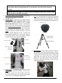
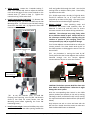
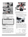
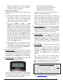
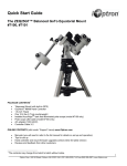
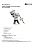
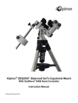
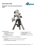
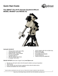
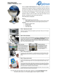
Quick Start Guide ZEQ25GT™ Center‐Balanced GoTo Equatorial Mount Models: #7100, #7101, #7102 PACKAGE CONTENTS1 Telescope mount – with GPS, and AccuAligningTM dark field illuminated Polar Scope (except Model #7101) Hand controller (HC) – Go2Nova® #8408 Tripod with accessory tray – 1.5‐inch size (#7100) or 2‐inch (#7102) Counterweight – 10.4 lbs X1 (4.7 kg) Counterweight shaft Polar scope LED cable (except Model #7101) Controller cables – qty. 2 AC adapter – 100‐240V ONLINE RESOURCES (at www.iOptron.com, under “Support”) User’s Manual Tips for set up and using the products Hand controller and mount firmware upgrades (check online for the latest version) Reviews and feedbacks from other customers REV. 2.0 1 Packaging may change from time to time without notice. 1 iOptron Corp. | 6E Gill Street | Woburn, MA 01801 USA | (781) 569-0200 | Toll Free (866) 399-4587 | www.iOptron.com WARNING: Read this QSG and full manual before operation. Make sure the Tension Adjuster is set properly. Worm system damage due to user operation error will not be covered by warranty. WARNING: Never disengage Gear Switches without holding the mount firmly! Personal injury and/or equipment damage may happen. Remove the mount from the package: The mount is shipped with R.A. gear disengaged to protect the worm/gear system. 2. Latitude Range: The mount is by default shipped with the Long Latitude Adjustment Knob installed (for 35‐60°). At lower latitudes of 0‐35⁰, the Short Latitude Adj. Knob needs to be used. To change this knob, remove the Latitude Locking T‐bolts on both sides (do not lose the 4 washers). Unscrew Bottom Post Locking Screw to free the Bottom Latitude Adj. Post and remove the Latitude Adj. Knob. Thread in evenly the adequate Latitude Adj. Knob to Top and Bottom Latitude Adjustment Posts. Reinstall and tighten bottom locking screw. Lastly, with 4 washers all properly placed, insert and tighten Latitude Locking T‐bolts into the upper threaded holes. 1. Short Lat. Adj. Knob [TIP: The removable Alignment Peg may be placed at the opposite location on the tripod head should the scope hit the tripod leg at high latitudes. This does not change the setup configuration described above.] Alignment Peg Center Rod Knob Accessory Tray Level Bubble Tray Locking Knob Lat. Locking T -bolt Bottom Lat. Adj. Post Bottom Post Locking Screw 4. Latitude Scale Long Lat. Adj. Knob For Low Latitudes For High Latitudes Attach Mount: Back out both Azimuth Adj. Knobs to allow enough clearance inside the chamber. Position the mount on the tripod head with the Alignment Peg in between the 2 Azimuth Adj. Knobs. Thread the Center Rod into mount to secure it with tripod. Tighten the Tray Locking Knob to fully spread the tripod legs. Adjust the tripod legs to level the mount using the Level Bubble. Azi . Adj. Knob 3. Tripod Setup: The Alignment Peg should be at the north side for northern hemisphere, and vice versa. Thread the tripod Center Rod through tripod head and insert the Accessory Tray and the Tray Locking Knob. Leave Tray Locking Knob slightly loose. 2 iOptron Corp. | 6E Gill Street | Woburn, MA 01801 USA | (781) 569-0200 | Toll Free (866) 399-4587 | www.iOptron.com 5. 6. Adjust Latitude: Loosen the 2 Latitude Locking T‐ bolts. Turn Latitude Adj. Knob to adjust the latitude until the arrow points to the current latitude on the Latitude Scale (2nd photo in Step 1). Tighten the Latitude Locking T‐bolts when done. Install Counterweight (CW) Shaft: (1) Remove CW Shaft Locking Screw. (2) Insert CW Shaft into the CW Mounting Nose. (3) Thread in the CW Shaft Locking Screw from the other side. (4) Tighten the Front CW Position Screw. CW Mounting Nose shaft end, guide CW through the shaft. Use the CW Locking Screw to hold the CW in place. Place Safety Cap back onto the shaft. [TIP: ZEQ25 comes with a 10.4 lbs (4.7 kg) CW, which should be sufficient for an 8” scope with total payloads up to about 13 lbs (6kg). Use extra CW or CW Extension Bar to balance higher payloads.] 8. Balance Payload: After attaching scope and accessories, the mount head assembly must be balanced in both R.A. and DEC axes to ensure minimum stresses on the mount driving mechanism. CAUTION: The telescope may swing freely when R.A. or DEC Gear Switch is open. Always hold on to the telescope assembly before opening the gear switches to prevent it from swinging, which can cause personal injury and/or equipment damage. (1) CW Shaft Locking Screw Turn Tension Adjuster counterclockwise to relieve the contact pressure. Turn Gear Switch Knob by 90° to the OPEN position to disengage the worm from the worm wheel. [TIP: Any hesitation in turning the knob by 90° usually means that the Tension Adjuster has not been loosened enough; turn the Tension Adjuster counterclockwise by one or more turns further.] Front CW Position Screw Tension Adjusters (3) CW Shaft inserts into CW mounting nose. (2) Gear Switch LOCK OPEN CAUTION: The balance process MUST be done with Gear Switch at OPEN position! Otherwise it might damage the worm system. Rear CW Position Screw 7. [TIP: At very low latitudes (<10°), to avoid CW bumping into tripod leg, turn the Rear CW Position Screw (a hex head set screw) further into CW Mounting Nose before tightening the Front CW Positioning Screw.] Install Counterweight: Remove CW Safety Cap at the end of CW Shaft. With the wider opening towards the With the corresponding Gear Switch in the OPEN position, balance the assembly in R.A. axis by moving CW along its shaft, and balance in DEC axis by moving the scope with accessories back and forth (see photos below). Only balance one axis at a time and start with the DEC axis first. Double check the mount to make sure both the RA and DEC axes are balanced. 3 iOptron Corp. | 6E Gill Street | Woburn, MA 01801 USA | (781) 569-0200 | Toll Free (866) 399-4587 | www.iOptron.com Polar Axis Cover Polar Axis (R.A. axis) Lat. Locking T-bolt Lat. Adj. Knob R.A. balance Azi. Adj. Knob DEC balance Return the mount to Zero Position after balancing; i.e., CW Shaft points to ground, and telescope tip is at its highest position. Turn Gear Switch Knob by 90° to LOCK position to re‐ engage the worm to the worm wheel. Retighten the Tension Adjuster as the last step to lock the gear (see Notes below). Important Notes on Tension Adjusters The rule of thumb is to fully screw in the Tension Adjuster and then back out by about ¼ ‐ 2 turns. The optimum spot varies with actual conditions. Ideally, it should be at a position just deep enough to rid any free movements (plays), while force on the worm assembly is kept at a minimum. Please refer to User’s Manual for more details. 9. Connect Cables: Use the short straight RJ11 cable to connect the DEC Control Unit to the Main Control Unit. Connect the Go2Nova® 8408 Hand Controller to the HC port on the main unit. Plug in a 12V DC power supply to the POWER socket. 10. Polar Alignment: Remove both Polar Scope covers. Look through the polar scope to locate Polaris (or Sigma Octantis at southern hemisphere). Slightly loosen the Tripod Center Rod Knob. Use the two Azimuth Adjustment Knobs to center the pole star in the azimuth direction, followed by tightening the Center Rod Knob. Slightly loosen 2 Latitude Locking T‐bolts, use the Latitude Adjustment Knob to adjust the latitude. Tighten the 2 locking T‐bolts. Polar Scope Cover Quick Polar Alignment Fast and accurate polar alignment can be performed with iOptron’s AccuAlignTM Polar Scope. (1) Connect the Polar Scope illumination LED to the Reticle socket located on the main control board. Turn the mount power on. Use the Hand Controller (“Set Up Controller” => “Set Polar Scope Light”) to set illumination intensity. Polar Scope LED (2) Use the Hand Controller (MENU => “Align” => “Pole Star Position”) to display the Polaris Position on the LCD screen, as indicated in the left side of the figure below. For example, on May 30th, 2010, 20:00:00 at Boston, US (lat N42⁰30’32” and long W71⁰08’50”), 300 min behind UT, the Polaris Position is at 1h26.8m and 41.5m (3) Use the Azimuth and Latitude Adj. Knobs to adjust the mount in both directions and put the 4 iOptron Corp. | 6E Gill Street | Woburn, MA 01801 USA | (781) 569-0200 | Toll Free (866) 399-4587 | www.iOptron.com Polaris in the location on the Polar Scope Dial (same as indicated on the HC LCD), as shown in the right side of the above figures. BrightStar Polar Alignment When the pole star is not in sight or no polar scope is installed: (1) Level the mount and set it at Zero Position. Align the telescope parallel to the R.A. axis of the mount. Set the correct R.A. and DEC backlash values (refer to the full User’s Manual). An eyepiece with crosshairs is recommended. (2) Use the HC (MENU => “Align” => “Polar Alignment”) to display the azimuth and altitude position of several bright stars near meridian. Select one that is visible and high in altitude as the Alignment Star A. Follow the HC instructions to move the Star A to the center of the eyepiece with the combination of using Latitude Adj. Knob and “◄” / “►” buttons. Press ENTER to confirm the centering. Next, select a bright star that is close to the horizon as the Alignment Star B. Center it using Azimuth Adj. Knob and “◄” / “►” buttons (The “▲” and “▼” buttons are not used here). Press ENTER to confirm. (3) The telescope will now slew back to Star A to repeat above steps. The iterations can be stopped when it is determined that the alignment error has been minimized. Press the BACK button to exit the alignment procedure. 11. Manual Operation: The mount can now be used to observe astronomical objects with the HC. Use arrow keys (►, ◄, ▼, and ▲) to point the telescope to the desired object. Use the number keys to change the slewing speed. Press STOP/0 button to start tracking. 12. Set Up Controller: Press the MENU button; then “Set Up Controller” => “Set Up Time & Site”. Enter the current date and check for Daylight Saving Time using arrow and number keys. Enter time zone (in 60‐minutes increment) by entering minutes “behind” or “ahead of” UT; for examples: Boston is 300 minutes “behind” UT Los Angeles is 480 minutes “behind” UT Rome is 60 minutes “ahead” of UT Sydney is 600 minutes “ahead” of UT Move the cursor to the end of screen to select the Northern or Southern Hemisphere. [TIPS: All time zones in N. America are “behind” UT. Latitude and longitude coordinates can be obtained from GPS‐equipped devices (navigator, phone), or from internet. “W/E” = western/eastern hemisphere; “N/S” = northern/southern hemisphere; and “d” = degree; “m” = minute; and “s” = second. Use arrow and number keys to enter location information.] 13. One Star Alignment: Make sure the mount is at ZERO position by press MENU => “To Zero Position”. Perform a One Star Align to correct the Zero Position discrepancy. To further improve the GOTO accuracy, refer to the full User’s Manual for more details. 14. Go to an Object: The mount is now ready for GOTO and tracking targets. Press MENU, select and ENTER “Select and Slew”. Select a category (for example, “Planets, Sun, Moon”), then select an object of interest (for example, “Moon”). Press ENTER and the telescope will slew to the object and automatically start tracking. 15. Sync to Target: If the object is not in the center of the eyepiece, use this function to center and synchronize the object to improve local GOTO accuracy. Press MENU and select and ENTER “Sync to Target”. Use arrow keys center the object in eyepiece. Press ENTER again to complete this function. [TIP: “Sync to Target” can only function after a “Select and Slew” operation. This is most useful when looking for faint objects near a bright star. ] [TIP: After slewing to an object, a list of nearby bright object(s) can be displayed by pressing “?” button.] Reminder on Tension Adjusters The Tension Adjusters are used as the last step to lock, and the first step to release the gears. Never fully tighten them during operations. The optimum position is one just deep enough to rid any plays. Hesitation in turning the Gear Switch by 90° means the Tension Adjuster has not been loosened enough. Use [email protected] for technical supports. 5 iOptron Corp. | 6E Gill Street | Woburn, MA 01801 USA | (781) 569-0200 | Toll Free (866) 399-4587 | www.iOptron.com IOPTRON TWO YEAR TELESCOPE, MOUNT, AND CONTROLLER WARRANTY A. iOptron warrants your telescope, mount, or controller to be free from defects in materials and workmanship for two years. iOptron will repair or replace such product or part which, upon inspection by iOptron, is found to be defective in materials or workmanship. As a condition to the obligation of iOptron to repair or replace such product, the product must be returned to iOptron together with proof-ofpurchase satisfactory to iOptron. B. The Proper Return Merchant Authorization Number must be obtained from iOptron in advance of return. Call iOptron at 1.781.569.0200 to receive the RMA number to be displayed on the outside of your shipping container. All returns must be accompanied by a written statement stating the name, address, and daytime telephone number of the owner, together with a brief description of any claimed defects. Parts or product for which replacement is made shall become the property of iOptron. The customer shall be responsible for all costs of transportation and insurance, both to and from the factory of iOptron, and shall be required to prepay such costs. iOptron shall use reasonable efforts to repair or replace any telescope, mount, or controller covered by this warranty within thirty days of receipt. In the event repair or replacement shall require more than thirty days, iOptron shall notify the customer accordingly. iOptron reserves the right to replace any product which has been discontinued from its product line with a new product of comparable value and function. This warranty shall be void and of no force of effect in the event a covered product has been modified in design or function, or subjected to abuse, misuse, mishandling or unauthorized repair. Further, product malfunction or deterioration due to normal wear is not covered by this warranty. IOPTRON DISCLAIMS ANY WARRANTIES, EXPRESS OR IMPLIED, WHETHER OF MERCHANTABILITY OF FITNESS FOR A PARTICULAR USE, EXCEPT AS EXPRESSLY SET FORTH HERE. THE SOLE OBLIGATION OF IOPTRON UNDER THIS LIMITED WARRANTY SHALL BE TO REPAIR OR REPLACE THE COVERED PRODUCT, IN ACCORDANCE WITH THE TERMS SET FORTH HERE. IOPTRON EXPRESSLY DISCLAIMS ANY LOST PROFITS, GENERAL, SPECIAL, INDIRECT OR CONSEQUENTIAL DAMAGES WHICH MAY RESULT FROM BREACH OF ANY WARRANTY, OR ARISING OUT OF THE USE OR INABILITY TO USE ANY IOPTRON PRODUCT. ANY WARRANTIES WHICH ARE IMPLIED AND WHICH CANNOT BE DISCLAIMED SHALL BE LIMITED IN DURATION TO A TERM OF TWO YEARS FROM THE DATE OF ORIGINAL RETAIL PURCHASE. Some states do not allow the exclusion or limitation of incidental or consequential damages or limitation on how long an implied warranty lasts, so the above limitations and exclusions may not apply to you. This warranty gives you specific legal rights, and you may also have other rights which vary from state to state. iOptron reserves the right to modify or discontinue, without prior notice to you, any model or style telescope. If warranty problems arise, or if you need assistance in using your telescope, mount, or controller contact: iOptron Corporation Customer Service Department 6F Gill Street Woburn, MA 01801 www.ioptron.com [email protected] Tel. (781)569-0200 Fax. (781)935-2860 Monday-Friday 9AM-5PM EST NOTE: This warranty is valid to U.S.A. and Canadian customers who have purchased this product from an authorized iOptron dealer in the U.S.A. or Canada or directly from iOptron. Warranty outside the U.S.A. and Canada is valid only to customers who purchased from an iOptron Distributor or Authorized iOptron Dealer in the specific country. Please contact them for any warranty. 6 iOptron Corp. | 6E Gill Street | Woburn, MA 01801 USA | (781) 569-0200 | Toll Free (866) 399-4587 | www.iOptron.com