1
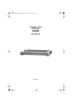
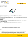
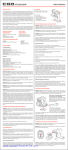
MiniView™ ULTRA
8 Port KVM Switch (GCS138 Installation Manual)
©2001 IOGEAR. All Rights Reserved.
IOGEAR, the IOGEAR logo, MiniView, and VSE are trademarks or registered trademarks of IOGEAR, Inc.
Microsoft and Windows are registered trademarks of Microsoft Corporation. IBM is a registered trademark of International Business Machines, Inc.
Macintosh, G3/G4 and iMac are registered trademarks of Apple Computer, Inc. IOGEAR makes no warranty of any kind with regards to the
information presented in this document. All information furnished here is for informational purposes only and is subject to change without notice. IOGEAR,
Inc. assumes no responsibility for any inaccuracies or errors that may appear in this document.
Thank you for purchasing one of the most feature-rich KVM switches on the market. IOGEAR’s KVM
switches are first-rate connectivity accessories designed to help reduce the frustration of managing multiple
computer systems. With the MiniView™ ULTRA series by IOGEAR, you can access multiple computers
from a single console(keyboard, mouse and monitor). The MiniView™ ULTRA provides three convenient
methods to access connected computers. Change ports easily via the push button selection switch located
on the front of the KVM, or by entering Hot Key combinations from the keyboard, or through the OSD (OnScreen-Display). Setup is fast and easy; plugging cables into their appropriate ports is all that is entailed.
We hope you enjoy using your MiniView™ ULTRA KVM Switch, yet another first-rate connectivity solution
from IOGEAR.
Table of Contents
Table of Contents:
Package Contents
Overview
Features
Requirements
Introduction
Installation
On-Screen-Display (OSD) Operation
Power Off
Port ID Numbering
Port Selection
Function Keys
Appendix (Troubleshooting)
Specification
Radio & TV Interference Statement
○
○
○
○
○
○
○
○
○
○
○
○
○
○
○
○
○
○
○
○
○
○
○
○
○
○
Limited Warranty
○
○
○
○
○
○
○
○
○
○
○
○
○
○
○
○
○
○
○
○
○
○
○
○
○
○
○
○
○
○
○
○
○
○
○
○
○
○
○
○
○
○
○
○
○
○
○
○
○
○
○
○
○
○
○
○
○
○
○
○
○
○
○
○
○
○
○
○
○
○
○
○
○
○
○
○
○
○
○
○
○
○
○
○
○
○
○
○
○
○
○
○
○
○
○
○
○
○
○
○
○
○
○
○
○
○
○
○
○
○
○
○
○
○
○
○
○
○
○
○
○
○
○
○
○
○
○
○
○
○
○
○
○
○
○
○
○
○
○
○
○
○
○
○
○
○
○
○
○
○
○
○
○
○
○
○
○
○
○
○
○
○
○
○
○
○
○
○
○
○
○
○
○
○
○
○
○
○
○
○
○
○
○
○
○
○
○
○
○
○
○
○
○
○
○
○
○
○
○
○
○
○
○
○
○
○
○
○
○
○
○
○
○
○
○
○
○
○
○
○
○
○
○
○
○
○
○
○
○
○
○
○
○
○
○
○
○
○
○
○
○
○
○
○
○
○
○
○
○
○
○
○
○
○
○
○
○
○
○
○
○
○
○
○
○
○
○
○
○
○
○
○
○
○
○
○
○
○
○
○
○
○
○
○
○
○
○
○
○
○
○
○
○
○
○
○
○
○
○
○
○
○
○
○
○
○
○
○
○
○
○
○
○
○
○
○
○
○
○
○
○
○
○
○
○
○
○
○
○
○
○
○
○
○
○
○
○
○
○
○
○
○
○
○
○
○
○
○
○
○
○
○
○
○
○
○
○
○
○
○
○
○
○
○
○
○
○
○
○
○
○
○
○
○
○
○
○
○
○
○
○
○
○
○
○
○
○
○
○
○
○
○
02
03
04
05
07
12
19
23
25
26
28
35
37
39
40
Package Contents
This package contains:
1 MiniView™ ULTRA KVM switch (GCS138)
1 User Manual
1 Registration Card
1 Power Adapter
1 Quick Start Guide
If any items are damaged or missing please contact your dealer.
2
Overview
Overview
The MiniView™ ULTRA GCS138 KVM (Keyboard, Video, Mouse) Switch is a control unity that allows access
to eight computers from a single console (keyboard, mouse and monitor). Before the development of the
MiniView™ ULTRA, the only way to control multiple computer configurations from a single console was
through a complex and costly network system.
setup is fast and easy, plugging cables into their appropriate posts is all that is entailed. We have arrange so
the 2 PS/2 console ports are on the front of the unit for easy and convenient access. There is no software to
configure, so there is no need to get involved in complex installation routines or be concerned with incompatibility problems. Since the MiniView™ ULTRA GCS138 intercepts keyboard input directly, it works on any
hardware platform and with all operating systems.
The MiniView™ ULTRA GCS138 provides two convenient methods to access the computers connected to
the system using push button selection switches located on the units front panel and entering Hotkey
combinations from the keyboard.
There is no better way to save time and money than with a MiniView™ ULTRA GCCS138. By allowing a
single console to manage the attached computers, the MiniView™ ULTRA GCS138 eliminates the expense
of purchasing a separate keyboard, monitor and mouse. Additionally, it saves space taken up by the
additional hardware and eliminates the inconvenience of switching from the different computer systems.
3
Features
Features
-
Cascadable To Three Levels - Control Up to 512 PCs From a Single Console
No Software Required
PC Selection Via Front Panel Switches, HotKeys, or OSD (On Screen Display)
Quick View Scan Feature for Monitoring Selected PCs
PS/2 and Serial Mouse Emulation Provided For System Bootup
Console’s PS/2 Mouse Controls All Connnected PCs - Even Those With Serial Mice
PS/2 Compatible Mouse Support - Microsoft Intellimouse Pro, Logitech FirstMouse Support*
SVGA, VGA and Multisync Monitor Support
Superior Video Quality; 1920 x 1440; DDC, DDC2, DDC2B
LED Display For Easy Status Monitoring
Rack Mountable in 19” System Rack
Hot Pluggable - Add or Remove PCs for Maintenance Without Powering Down the Switch
* 1. PS/2 compatible mouse support is for three button (wheel) mice.
2. The Logitech Mouse Ware program’s change device procedure does not work on Microsoft NT systems.
4
Requirements
Requirements
Console
- A VGA, SVGA, or Multisync monitor capable of the highest resolution that you will be using on any PC in the installation
- A PS/2 Style Mouse
- A PS/2 Style Keyboard
PC: The following equipment must be installed or on board each PC that is to be connected to the system:
- A VGA, SVGA or Multisync card.
- Either a 6-pin mini-DIN (PS/2 style), or DB-9 (standard serial), mouse port
- Either a 6-pin mini-DIN (PS/2 Style) keyboard port with _5V DC on pin 4 and Ground on pin 3, or a 5-pin DIN (AT Style) keyboard port with +5V DC on
pin 5 and ground on pin 4.*
5
Requirements
NOTE:
1. If your PC uses a standard AT style keyboard socket you will need to purchase a PS/2-to-AT keyboard adapter (Part No. 2A-106, or any standard
keyboard adapter), in order to plug the cable into the computer’s keyboard port.
2. If your PC uses standard 9 pin serial port for the mouse, you will need to purchase a PS/2-to-Serial mouse adapter (Part No.2A-105; a standard mouse
adapter will probably not work). In order to plug the cable into the computer’s serial port.
3. Because of the wiring and pin assignments, you cannot use a Serial-to-PS/2 adapter at the end that plugs into the GCS138.
6
Introduction
Introduction on MiniViewTM ULTRA
The MiniViewTM ULTRA GCS138 is a KVM switch that controls access to multiple computers from a single console (keyboard,
monitor, and mouse). Before the development of the MiniViewTM ULTRA, the only way to control multiple computer configurations from a single console was through a complex and costly network system. Now, with the MiniViewTM ULTRA, you can
easily access multiple computers in a simple and cost effectively manner.
One MiniViewTM ULTRA can control up to eight PCs. Units can be cascaded to three levels, which means that as many as 73
MiniViewTM ULTRA units can control up to 512 PCs - all from a single console.
Setup is fast and easy; just plug the cables into their appropriate ports. There is no software to configure so there is no
need to get involved in complex installation routines or be concerned with incompatibility problems. Since the MiniViewTM
ULTRA accepts keyboard input directly, it works virtually any hardware platform with all operating systems.
The MiniViewTM ULTRA provides three convenient methods to access any PC connected to the system: (1) using the port
selection buttons on the front panel of each unit; (2) entering Hotkey combinations from the keyboard; and (3) selecting from
on-screen menus through the On Screen Display (OSD) feature. In addition, a powerful Quick View Scan feature allows you
to auto scan and monitor the activities of all operating PCs on the installation one by one.
There is no better way to save time and money than with a MiniViewTM ULTRA. By allowing the MiniViewTM ULTRA to manage
all the attached PCs, there is no need to purchase a separate keyboard, monitor, and mouse for each PC, saving an
enormous amount of space. It also eliminates the inconvenience and wasted effort involved in constantly moving around
from one PC to another.
7
Introduction
Front View
1, 2
4
3
5
1. Port LEDs
On Line: Lights BLUE to indicate that the PC attached to the corresponding port is up and running. If the LED is flashing,
it indicates that the Port is being used for Cascading to another MiniViewTM ULTRA switch. Selected: Lights Green to
indicate the current selected port. The LED is steady under normal conditions, but flashes when its port is accessed
under Auto Scan mode.
2. Port Selection Switches
Press a switch to access the PC attached to the corresponding port. Pressing Buttons 1 and 2 simultaneously for 3
seconds performs a Keyboard and Mouse reset; pressing Buttons 7 and 8 simultaneously starts Auto Scan Mode.
8
Introduction
3. MiniViewTM ULTRA Reset
To reset the MiniViewTM ULTRA, use a thin object (such as the end of a paper clip, or a ballpoint pen), to press this recessed
switch in to initiate a warm reset. If the switch is kept in for longer than three seconds, a cold reset takes place.
4. Sound Opening
System sounds (beeps,etc.), are emitted from this opening.
5. Power LED
Lights to indicate that the MiniViewTM ULTRA is receiving power.
9
Introduction
Back View
1
2
3
1. Power Jack
The power adapter plugs in here.
2. Console Port Section
If this is a first station unit. Your monitor, keyboard and mouse plug in here.
If this is a daisy chained unit. The cables that link back to a port on a higher MiniViewTM ULTRA unit plug in here.
3. Console Port Section
The cables that link to the PCs plug in here.
10
Introduction
11
Installation
Setup and Installation (Power Adapter)
Step. 1 (Power Adapter Connection)
* Before you begin, please make sure that the power to all devices has been turned off.
Connecting your console to the MiniViewTM ULTRA. You will need your VGA monitor, PS/2 mouse, PS/2 keyboard and the
MiniViewTM ULTRA power adapter.
NOTE: To prevent damage to your installation due to ground potential difference, make sure that all devices on the installation are properly grounded.
Consult your dealer for technical details, if necessary.
The Unit is designed to be non-powered (no external power required). Generally speaking, the only time that external power is
required is when you daisy chain it, or if operation becomes erratic because the unit isn’t obaining enough power from the
computer connections.
If you choose to use external power, plug the adapter into a standard surge protector, then plug the cable into the MiniViewTM
ULTRA Power Jack.
12
Installation
Setup and Installation (Console Port Connection on KVM Switch)
2
1
2
Step. 2 (Console Connection)
1. Connect the end of your monitor cable into the console side of the MiniViewTM ULTRA video port.
2. Plug in your PS/2 mouse and PS/2 keyboard into their designated ports on the console side of the MiniViewTM ULTRA.
13
Installation
Setup and Installation (CPU Port Connection on KVM Switch)
1
2
2
Step. 3 (CPU Port Connection)
1. Connect the female end of your IOGEAR video cable into the male video port on the MiniViewTM ULTRA labeled with a CPU
port number.
2. Plug in the PS/2 mouse and PS/2 keyboard connectors located on the same end as the female video connector. The
cables have images on them indicating that they are for the keyboard or mouse.
14
Installation
Setup and Installation (Port Connections on back of Computer)
3
Step. 4 (Connecting the PCs)
3. Plug in the remaining PS/2 mouse and PS/2 keyboard connectors into your PC’s keyboard and mouse ports.
4. Repeat steps 1-3 for any additional computers you wish to connect to the MiniViewTM ULTRA.
NOTE: You may need to attach a PS/2 to AT adapter on the keyboard cable if your computer has an AT keyboard connection. Also, if you do not have a
PS/2 mouse port you will need to use our PS/2 to Serial adapter to connect the mouse cable. You can use any manufacturer’s PS/2 to AT
adapter but you must use our PS/2 to Serial adapters for the mouse.
15
Installation
Setup and Installation (Cascading MiniViewTM ULTRA)
1
2
2
Step. 5 (Cascading MiniViewTM Ultra Units)
* Use standard IOGEAR PS/2 cables to cascade units.
1. Connect the female end of your IOGEAR video cable into the male video port on an available CPU section of the
MiniViewTM ULTRA.
2. Plug in the PS/2 keyboard connectors located on the same end as the female video connector. The cables have images
on them indicating that they are for the keyboard or mouse.
16
Installation
Setup and Installation (Cascading MiniViewTM ULTRA)
3
4
4
Step. 6 (Cascading Cont.)
3. Now plug the male end of the video cable into the female video port on the secondary MiniViewTM ULTRA console section.
4. Plug in the remaining PS/2 mouse and PS/2 keyboard connectors into the keyboard and mouse ports on the secondary
MiniViewTM ULTRA console section.
5. Plug the power adapter into a standard surge protector, then plug the adapter cable into each MiniViewTM ULTRA Power
Jack.
Congratulations! You have now completed the installation
17
Cascading in pyramid format
(Cascading Diagram)
○
○
○
○
○
○
○
○
○
○
○
○
○
○
○
○
○
○
○
○
○
○
○
○
○
○
○
○
○
○
○
○
○
○
○
○
○
○
○
○
○
○
○
○
○
○
○
○
○
○
○
○
Step. 7 (Cascading In Pyramid format)
- Red connection indicate level 1 (8 computers)
- Green connection indicate level 2 (64 computers)
- Orange connection indicate level 3 (512 computers)
18
○
○
○
○
○
○
○
○
○
○
○
○
○
○
○
○
○
○
○
○
○
○
○
○
○
○
○
○
○
○
○
○
○
OSD Operation
OSD Operation
On Screen Display (OSD), provides a menu driven interface to handle the PC switching procedure. Although Hotkey
Switching still works, using OSD is a great deal more convenient - especially in large, daisy chained installations where a
great number of PCs are connected to a several MiniViewTM ULTRA GCS138 units, and it is difficult to keep track of which
port a particular PC is attached to.
* All operations start from the OSD Main Menu. To pop up the Main Menu, press the control key twice ([Ctrl] [Ctrl]):
Note: You can use either the left or right Ctrl keys, but they must both be on the same side (both left, or both right).
OSD always starts in List view, with the highlight bar at the same position it was in the last time it was closed.
Note: You can optionally change the OSD HotKey to the scroll Lock key, in which case you would press [Scrol Lock] [Scroll Lock].
- Use the Up and Down Arrow Keys to move up or down through the list one line at a time
- Use [Pg Up] and [Pg Dn] to move up or down through the list one screen at a time
- Click on the Up and Down Triangle symbols to move up or down through the list one line at a time
- Click on the Up and Down Arrow symbols to move up or down through the list one screen at a time
- To activate a port, move the Highlight Bar to it then press [Enter].
- [Esc] cancels the current selection, or dismisses the current menu and moves back to the menu one level above. if you are
at the highest menu level, it deactivates OSD.
After executing any action by pressing [Enter], you automatically go back to the menu one level above.
19
OSD Operation
OSD Main Menu Headings:
PN
This column lists the Port ID numbers (Station Number - Port Number) for all the CPU Ports on the installation.
The simplest method to access a particular PC (assuming you know which port it is attached to), is to use the
Navigation keys to move the Highlight Bar to the desired location, then pres [Enter].
QV
Ports that have been selected for Quick View scanning (See F2 and F4, below), have an arrowhead displayed in
this column to indicate so.
PC
Lists all the PCs that are Powered On and are On Line.
Name
If a port has been given a name (see F5, below), its name appears in this column.
20
OSD Operation
HotKey Navigation:
HotKey navigation can be used under OSD mode. To do this:
1. Activate the OSD by pressing the Ctrl key twice ([Ctrl] [Ctrl]).
2. From the Main Menu, you can go directly to any port by keying in [Ctrl+Alt+Shift], then the Port ID Nubmer, and then
pressing [Enter].
Note: With this method, although access switches to the port you just specified, the highlight bar on the OSD screen doesn’t move.
The Console now controls the PC that you have selected, and the OSD automatically closes.
When you key in the Port ID, note the following:
- You must key in the port ID and press [Enter] within 1 second for each keypress after pressing the [Ctrl+Alt+Shift] combination.
- Number keys must be pressed from the regular keyboard; not from the numeric keypad.
- The keys must be pressed and released one key at a time.
- If you submit an incorrect Port ID, an error message is displayed and you are returned to the OSD Main Menu.
21
OSD Operation
Access authorization
OSD Operation
In order to prevent unauthorized access to the computers, the OSD provides a password security feature. If a password has been set, the OSD will request
that the user specify it before allowing entry.
Setting a password:
1. Highlight this item, then press [Enter]. You are presented with a screen that allows you to key in your password. The password may be up to 8 characters
long, and can consist of any combination of letters and numbers (A-Z, 0-9).
2. Key in the new password, then press [Enter][ You are asked to key the password in again, in order to confirm that it is correct.
3. Key in the new password again, then press [Enter]. If the two entries match, the new password is accepted and the screen displays the following message:
SET PASSWORD OK (If the entries do not match, the scren displays the message:)
PASSWORD NOT MATCH ( in which case you must start again from the beginning.)
Note: To modify or delete a pevious password, access the pasword, access the Password function as in Step 1, above, then use the backspace or delete
key to erase the indivisual letter or numbers.
22
Power Off
Power Off and Restarting:
OSD Operation
If it becomes necessary to power off one of the MiniViewTM ULTRA units, before starting it back up you must do the following:
1. Shut down all the computers that are attached to it, as well as all the stations and all the computers that are daisy
chained down from it (all the child stations and the computers attached to them).
• If the unit is operating under Non-powered mode (without the optional power adapter), you must unplug the power cords of
any PCs that are connected to it that have the Keyboard Power on function, other wise the switch will still be receiving
power from the computer.
• If the unit is operating under external power, unplug the power adapter cable.
2. Wait 10 seconds, then power on the MiniViewTM ULTRA GCS138 stations back in, starting with the last station in the chain
and working back to the station you originally shut down.
3. After the MiniViews are up, power on the PCs, starting with the ones attached to the last station in the chain and working
back to the station you originally shut down.
23
Power Off
Hot Plugging:
The MiniViewTM GCS138 supports hot plugging, which means that components can be removed and added back into the
installation by unplugging their cables from the CPU ports without shutting the unit down. There are certain procedures that
must be followed in order for hot plugging to work properly:
- Hot Plugging CPU Ports:
1. The cable must be plugged back into the same port it was removed from.
2. The mouse cable must be plugged in before the keyboard cable.
3. After plugging the cable back in, you must perform a KVM Reset on the First Stage unit (by pressing the Reset switch).
- Hot Plugging Console Ports:
1. You may unplug the mouse and plug it back in again (to reset the mouse, for example), as long as you use the same mouse.
2. If you plug in a different mouse, all the stations and all the computers on the installation must be shut down for 10 seconds, then restarted.
NOTE: All MiniViewTM ULTRA units must be plugged in and receiving power prior to turning on the power to the PCs. Press Port Selection Buttons 1 and
2 on the Level 1 unit simultaneously for 3 seconds to perfom a Keyboard and Mouse reset, if necessary.
24
Port ID Numbering
Since each CPU Port on a MiniViewTM installation is assigned a unique Port ID, you can directly access any computer on any
level. Specify the Port ID using the Hotkey port selection method or the OSD Main Menu.
The Port ID is a one, two, or three digit number that is determined by the Stage Level and CPU Port number of the MiniViewTM
unit that the computer is connected to. The first digit represents the CPU Port number of the First Stage unit; the second
digit represents the CPU Port number of the Second Stage; the third digit represents the CPU Port number of the Third
Stage.
For example, a computer attached to a First Sage unit has a one digit Port ID Number (1-8), that corresponds to the CPU
Port number that the computer is connected to.
A computer attached to a Second Stage unit has a two digit Port ID number. The first digit represents the CPU Port number
(1-8), on the First Stage unit that the second Stage unit is cascaded down from; the second digit represents the CPU Port
number on the second Stage unit that the computer is connected to. For example, a Port ID of 23 refers to a computer that
is connected to CPU Port 3 of a Second Stage unit that, in turn, is cascaded down form CPU Port 2 of the First Stage unit.
25
Port Selection
HotKey In Examples:
1. To access a computer attached to Port 3 of a Single Stage installation, key in 3 for the Port ID, as follows:
[Ctrl+Alt+Shift] 3 [Enter]
2. To access a computer attached to Port 3 of a second Stage unit that is cascaded down from Port 2 of the First Stage unit,
key in 23 for the Port ID, as follows: [Ctrl+Alt+Shift] 2 3 [Enter]
NOTE: You must key in the numbers one at a time.
3. To access a computer attached to Port 1 of a Third Stage unit that is cascaded down from Port 4 of a Second Stage unit,
which, in turn, is cascaded down from CPU Port 2 of the First Stage unit key in 241 for the Port ID, as follows:
[Ctrl+Alt+Shift] 2 4 1 [Enter]
Port Selection:
Controlling all the PCs connected up in your MiniViewTM ULTRA GCS138 installation from a single console could not be easier.
Four methods are available that provide instant access to any PC on the chain: Manual, Quick View Scanning, Hotkey, and
OSD.
26
Port Selection
- Manual
Simply press the appropriate port selection switch on the MiniViewTM ULTRA front panel. After you press the switch, the selected LED lights to indicate that
the port is currently selected. The On Screen Display automatically switches to highlight the PC that you have selected.
NOTE: On a daisy chained installation, you must press the Port Selection switch on the MiniViewTM ULTRA station that connects directly to the PC you
want to access.
- Quick View Scanning
Press Port Selection buttons 7 and 8 simultaneously for three seconds to start the Quick View mode. This will cycle through the ports one at a time.
Press the [Space Bar] or a port key to stop it.
- HotKey
HotKey navigation allows you to conveniently access connected PCs directly from the keyboard, instead of having to manually select them by pressing
Port Selection switches. To select a port with the HotKey method, do the following:
1. Press [Ctrl] [Alt] [Shift] individually to invoke the HotKey function.
2. Key in the Port ID number, then press [Enter].
Note: After invoking the HotKey function with the [Ctrl+Alt+Shift] combination, you must key in the Port ID and press [Enter] within one second for each
keypress.
Hotkey Summary Table:
Combination
Acti on
[ctr]+[ctr] or or [scroll lock]+[scrol l lock]
Open OSD Menu
[ctr]+[port number]+[Enter]
To select desired port
27
Function Keys
Function Keys:
Pressing a Function Key brings up a related submenu that is used to configure and control the OSD to make it convenient
for you to work with. For example, you can: rapidly switch to any port; scan selected ports only; limit the list you wish to
view; designate a port tobe included in the Quick View scan group; create or edit a port name; or make OSD setting
adjustments.
F1 GoTo:
GoTo allows you to switch directly to a port by the following methods:
a) Move the Highlight Bar to the port you want then press [Enter] or Double Click with the left mouse button.
b) Key in the Port ID or Name, then press [Enter].
NOTE: GoTo has a special feature that narrows the list of available choices as you type the name. For example,if the first letter you type is a, the list only
displays those ports whose names begin with a. If the next letter you type is b, the list is further narrowed down to only those ports whose names
begin with ab, etc.
Return to the OSD Main Menu without making a choice, press [Esc].
F2 Scan:
Pressing [F2] initiates Quick View Scanning, in which the OSD cycles through all the ports that are currently selected in the
List view (see F3, below), and displays each one for the amount of time set with the Set Scan Duration function (see F6,
below). When you want to stop at a particular location, press the [spacebar] to stop scanning.
28
Function Keys
NOTE: (1) If the scanning stops on an empty port, or one where the computer is attached but is powered off, the monitor screen will be blank,and the
mouse and keyboard will have no effect. To recover, key in the HotKey sequence (see HotKey Selection, above) for any Port ID that has an
active PC attached.
(2) As the OSD cycles through the selected ports, an S appears in front of the Port ID display as each computer is accessed to indicate that the
computer is being accessed under Quick View Scan Mode.
F3 List:
This function brings up a submenu that lets you broaden on arrow the scope of which ports the OSD lists. The choices and
their meanings are given in the following table. To make a choice, move the Highlight Bar to it, then press [Enter]. An icon
appears before the choice to indicate that it is the currently selected one.
Choice: Meaning
All: Lists the Port ID numbers and Names (if names have been specified -see F5) of all the ports on the installation.
Qview: Lists only the ports that have been selected for Quick View (see F4, below).
Powered On + QView: Lists only the ports that have been selected for Quick View scanning (see F4, below), and that have their attached PCs Powered
On.
QView+ Name: Lists only he ports that have been selected for Quick View scanning (see F4, below), and have been assigned names (see F5,
below).
Name: Lists only the ports that have been assigned names (see F5, below).
Powered On: Lists only the ports that have their attached PCs Powered On.
29
Function Keys
NOTE: (1) You can access any port on any list by using the Navigation Keys or Mouse to move the Highlight Bar to it, then pressing [Enter].
(2) If you select a port that does not have a PC attached to it,or if the attached PC is powered Off, the OSD will still switch to it, and will not show
an error.
F4 QV:
You can broaden or narrow the number of ports that get automatically scanned by selecting only the ones you want. [F4] is
toggle switch that selects or deselects ports for Quick View Scanning (see F2, above).
To select/deselect a port:
1. Use the Up and Down Arrow Keys to move the highlight bar to the port.
2. Press [F4].
When a port has been selected for Quick View Scanning, an arrowhead displays in the QV column. When a port is deselected, the arrowhead disappears.
30
Function Keys
F5 Edit:
For convenience in remembering which PC is attached to a particular port, every port can be named. The Edit function allows
you to name the currently highlighted CPU Port (if it doesn’t already have a name), or to modify/delete the Port Name if it
does. To edit a Port Name:
1. Use the Navigation Keys to move the highlight bar to the port you want (you can use the F3 List function to broaden or narrow the port selection list).
2. Press [F5].
3. Add, modify or delete the Port Name. Legal characters include:
- All alpha characters: a-z; A-Z
- All numeric characters: 0-9
- +,-,/,:,., and Space
Case does not matter; OSD displays the Port Name in all capitals no matter how they were keyed in.
4. When you have finished editing, press [Enter] to have the change take effect. To abort the change, press [Esc].
31
Function Keys
F6 Set:
When you press [F6] an OSD configuration submenu opens. To change a setting, move the highlight bar to the choice you
want, then press [Enter]. On the submenu that appears next, move the highlight bar to the choice you want and press [Enter].
An icon of a pointing finger indicates which choice is the currently selected one.
An explanation of the choices is given in the table (right):
Setti ng
Functi on
Channel Display Durat ion
Determines how long a Port ID is displayed for. There are two choices: 3 seconds - which displays the Port ID for 3
seconds after a port change has taken place; and Always On - which displays the Port ID at all times.
Channel Display Postit ion
Allows you to position where the Port ID is shown on t he screen. After you highlight this item an press [Ent er] , the
menu disappears and the Port ID is displayed. Use the Arrow Keys, Pg Up, Pg Dn, Home, to posit ion t he Port ID
display, then press [Enter] to lock the position and return to the Set submenu.
Channel Display Mode
Select how the Port ID is displayed. There are three choices: the Number plug the Name (PN + NAME); the Number
alone (PN); or the Name alone (Name).
Scan Durat ion
Determines how long the display pauses on each port when it cycles through the selected ports in Quick View Scan
Mode. The available opt ions are: 3, 5,10,15, 20,30, 40, and 60 seconds.
Clear t he Name List
Clears all Port Names from the Name List. You are asked to confirm before the procedure goes on. Key in Y, then
press [ Enter] to confirm. While the names are being cleared, a message appears on the display to indicate so. After
the names have been cleared, another message appears to indicate that the procedure completed successfully.
32
Function Keys
Setti ng
Functi on
Restore Default Values
Clear all settings from memory, and returns the unit to the fact ory defaults. you are asked to conf irm before
the procedure goes on. Key in Y, then press [Enter] to compfirm. While the settings are being cleared, a
message a appears on the display to indicate so. After the settings have been cleared, another message
appears to indicate that the procedure completed successfully.
OSD Activating Hotkey
Selects which Hotkey combination will activate the OSD function: [Ctrl] [Ctrl] or [Scroll Lock] [Scroll Lock].
The default is the Ctrl key combinaion, but this may conflict with programs running on the computers, in
which case, the scroll Lock opt ion should be selected.
Set Password
Allows you to set a password in order to control access to Locking/Unlocking the Console (see the OSD
Security Features section, below, for det ails).
Factory Default Settings: The factory default settings are as follows:
Setti ng
Default
Display Durat ion
Always On
Display Mode
The Port Number plus the port Name
Scan Duration+
5 Seconds
33
PC Connection Table
MiniView™ ULTRA: PC Connection Table
The following table indicates the relationship between the number of MiniView™ ULTRA units and the number of PCs that they
control:
MVs
PCs
MVs
PCs
MVs
PCs
MVs
PCs
MVs
PCs
01
00-08
14
92-99
27
183-190
40
274-281
53
365-372
02
08-15
15
99-106
28
190-197
41
281-288
54
372-379
03
15-22
16
106-113
29
197-204
42
288-295
55
379-386
386-393
04
22-29
17
113-120
30
204-211
43
295-302
56
05
29-36
18
120-127
31
211-218
44
302-309
57
393-400
06
36-43
19
127-134
32
218-225
45
309-316
58
400-407
07
43-50
20
134-141
33
225-232
46
316-323
59
407-414
08
50-57
21
141-148
34
232-239
47
323-330
60
414-421
09
57-64
22
148-155
35
239-246
48
330-337
61
421-428
10
64-71
23
155-162
36
246-253
49
337-344
62
428-435
11
71-78
24
162-169
37
253-260
50
344-351
-
-
12
78-85
25
169-176
38
260-267
51
351-358
-
-
13
85-92
26
176-183
39
267-274
52
358-365
73
505-512
34
Appendix
Troubleshooting (Model: GCS138)
Note: If the unit appears to be operating erratically, check all cables for damage and to be sure that they are properly connected. If you are operating
under nonpowered mode, use the external power adapter.
Symptom
Possible Cause
Acti on
Check the Online LED for the selected port. If it is not
lit;
The connection from the selectexd port to the target
PC has been broken, or the PC is turned OFF.
1. Manually press one of the Select switches to connect
to a PC that is powered ON.
2. Check the cables to make sure they are all properly
connected.
Pressing the Hot Keys gets
no response
1. Reset the keyboard (and mouse) by
simultaneously pressing But tons 1 and 2 on the First
St age unit for 3 seconds.
Improper Keyboard reset .
2. Unplug the keybaord connector from the Console
Keyboard Port, then plug it back in.
35
Appendix
Symptom
Possible Cause
Acti on
Turn of all MiniView TM ULTRA units and wait five
seconds before turning them back on.
Note: If the unit is operating under Bus Power (without
the optional Power Adapter), you must unplug the power
cords of any PCs that are connected to it that have the
Keyboard 'Power On' function, otherwise the swit ch will
still receive power from the PC.
I mproper MiniViewTM ULTRA reset.
Pressing the Hot Keys gets
no response
After involking the hotkey function with [Ctrl+Alt+Shift]
combination, be sure t o key in the port ID and press
(Enter) within 1 second for each key.
Incorrectly Keying in t he Port ID
1. Reset the mouse (and keyboard) by simultaneously
pressing Buttons 1 and 2 on the First Stage unit for 3
seconds.
Improper mouse reset
2. Unplug the mouse connector from the Console
Mouse Port, then plug it back in.
36
Specification
Product Specification
(MODEL: GCS138)
Functi on
Specificati on
Power Consumption
DC 9V, 1.08W (max.)
Computer Connections
Up to 8 PS/2 enabled comput ers / Up to 512 daisy chained
Pushbutton Switches, HotKeys, OSD
Port Selecti on
Keyboard Ports
Mouse Ports
Connectors
Video Ports
9 PS/2 Keyboard Ports (8 computer, 1 console)
9 PS/2 Mouse Ports (8 computer, 1 console)
1 VGA (HD15F) Port - Console
1 VGA (HD15M) Port - Computer
37
Specification
Functi on
Specificati on
Scan Interval (OSD Select)
3, 5, 10, 15, 20, 30, 40, 60 secs.
Resolution
1920 x 1440 DDC, DDC2, DDC2B
Operati ng Temperature
5 ~ 40° C
Storage Temperature
-20 ~ 60° C
Humidity
0 ~ 80% RH, Noncondensing
Housi ng
Metal
Weight
2850 g
Dimensi on (LxWxH)
483 x 150 x 44.5 mm (19" 1U)
38
Radio & TV Interference Statement
Radio & TV Interference Statement
WARNING!!! This equipment generates, uses and can radiate radio frequency energy and, if not installed and
used in accordance with the instruction manual, may cause interference to radio communications. This
equipment has been tested and found to comply with the limits for a Class B computing device pursuant to
Subpart J of Part 15 of FCC Rules, which are designed to provide reasonable protection against such
interference when operated in a commercial environment. Operation of this equipment in a residential area is
likely to cause interference, in which case the user at his own expense will be required to take whatever
measures may be required to correct the interference.
39
Limited Warranty
Limited Warranty
IN NO EVENT SHALL THE DIRECT VENDOR’S LIABILITY FOR DIRECT, INDIRECT, SPECIAL, INCIDENTAL OR CONSEQUENTIAL DAMAGES RESULTING FROM THE USE OF THE PRODUCT, DIST ORITS
DOCUMENTATION EXCEED THE PRICE PAID FOR THE PRODUCT.
The direct vendor makes no warranty or representation, expressed, implied, or statutory with respect to the
contents or use of this documentation, and especially disclaims its quality, performance, merchantability, or
fitness for any particular purpose.
The direct vendor also reserves the right to revise or update the device or documentation without obligation to
notify any individual or entity of such revisions, or updates. For further inquires please contact your direct
vendor.
40
41
Contact info.
23 Hubble Drive
•
Irvine, CA 92618
•
(P) 949.428.1111
•
(F) 949.428.1100
•
www.iogear.com