1
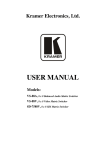
User’s Guide
EasyCoder® PD41
Printer
Intermec Technologies Corporation
Corporate Headquarters
6001 36th Ave.W.
Everett, WA 98203
U.S.A.
www.intermec.com
The information contained herein is proprietary and is provided solely for the
purpose of allowing customers to operate and service Intermec-manufactured
equipment and is not to be released, reproduced, or used for any other purpose
without written permission of Intermec.
Information and specifications contained in this document are subject to
change without prior noticed and do not represent a commitment on the part
of Intermec Technologies Corporation.
© 2005 by Intermec Technologies Corporation. All rights reserved.
The word Intermec, the Intermec logo, Norand, ArciTech, CrossBar, Data
Collection Browser, dcBrowser, Duratherm, EasyADC, EasyCoder, EasyLAN,
Enterprise Wireless LAN, EZBuilder, Fingerprint, i-gistics, INCA (under
license), InterDriver, Intermec Printer Network Manager, IRL, JANUS,
LabelShop, Mobile Framework, MobileLAN, Nor*Ware, Pen*Key, Precision
Print, PrintSet, Ready-to-Work, RoutePower, SmartSystems, TE 2000,
Trakker Antares, and Virtual Wedge are either trademarks or registered
trademarks of Intermec Technologies Corporation.
Throughout this manual, trademarked names may be used. Rather than put a
trademark (™ or ®) symbol in every occurrence of a trademarked name, we state
that we are using the names only in an editorial fashion, and to the benefit of
the trademark owner, with no intention of infringement.
There are U.S. and foreign patents pending.
Microsoft, Windows, and the Windows logo are registered trademarks of
Microsoft Corporation in the United States and/or other countries.
ii
EasyCoder PD41 Printer User’s Guide
Contents
Before You Begin. . . . . . . . . . . . . . . . . . . . . . . . . . . . . . . . . vii
Safety Information . . . . . . . . . . . . . . . . . . . . . . . . vii
Global Services and Support . . . . . . . . . . . . . . . . viii
Warranty Information . . . . . . . . . . . . . viii
Web Support . . . . . . . . . . . . . . . . . . . . viii
Telephone Support . . . . . . . . . . . . . . . viii
Who Should Read This Manual . . . . . . . . . . . . . . ix
Related Documents . . . . . . . . . . . . . . . . . . . . . . . ix
1 Getting Started
. . . . . . . . . . . . . . . . . . . . . . . . . . . . . .1
Description of EasyCoder PD41 . . . . . . . . . . . . . . . . . . . . . .2
Unpacking the Printer . . . . . . . . . . . . . . . . . . . . . .2
Product Identification. . . . . . . . . . . . . . . . . . . . . . .4
Front View . . . . . . . . . . . . . . . . . . . . . . . . . . . . . . .4
Controls and Indicators . . . . . . . . . . . . . .5
Rear View. . . . . . . . . . . . . . . . . . . . . . . . . . . . . . . .6
Connectors . . . . . . . . . . . . . . . . . . . . . . . . . . . . . . .6
Media Compartment . . . . . . . . . . . . . . . . . . . . . . .7
Print Mechanism . . . . . . . . . . . . . . . . . . . . . . . . . .7
Installing the Printer . . . . . . . . . . . . . . . . . . . . . . . . . . . . . . .8
Connecting the Printer to your System . . . . . . . . . .8
Connecting the Printer through the USB
interface . . . . . . . . . . . . . . . . . . . . . . .9
Connecting the Printer to a Network . . . .9
Connecting the Printer through the Serial
Port . . . . . . . . . . . . . . . . . . . . . . . . . . .9
Connecting the Printer through the Parallel
Port . . . . . . . . . . . . . . . . . . . . . . . . . .10
Printing a Test Label . . . . . . . . . . . . . . . . . . . . . . .10
2 Operating the Printer
. . . . . . . . . . . . . . . . . . . . . .11
Loading Media . . . . . . . . . . . . . . . . . . . . . . . . . . . . . . . . . .12
Tear-Off (straight-through) Operation . . . . . . . . .12
Tear-Off. . . . . . . . . . . . . . . . . . . . . . . . .12
Peel-Off (Self-Strip) Operation . . . . . . . . . . . . . . .15
Peel-Off . . . . . . . . . . . . . . . . . . . . . . . . .15
Loading Thermal Transfer Ribbon . . . . . . . . . . . .18
Loading Ribbon . . . . . . . . . . . . . . . . . . .18
EasyCoder PD41 Printer User’s Guide
iii
LED indicators and the Print Button . . . . . . . . . . . . . . . . . 21
LED indicators. . . . . . . . . . . . . . . . . . . . . . . . . . . 21
Print Button. . . . . . . . . . . . . . . . . . . . . . . . . . . . . 22
3 Maintaining the Printer
. . . . . . . . . . . . . . . . . . . 25
General Maintenance Advice . . . . . . . . . . . . . . . . . . . . . . . 26
Printhead Cleaning. . . . . . . . . . . . . . . . . . . . . . . . . . . . . . . 26
Internal Cleaning . . . . . . . . . . . . . . . . . . . . . . . . . . . . . . . . 27
External Cleaning . . . . . . . . . . . . . . . . . . . . . . . . . . . . . . . . 27
4 Troubleshooting
. . . . . . . . . . . . . . . . . . . . . . . . . . . . 29
Printer Operation Problems . . . . . . . . . . . . . . . . . . . . . . . . 30
Print Quality Problems . . . . . . . . . . . . . . . . . . . . . . . . . . . . 31
Ready-to-Work™ Indicator . . . . . . . . . . . . . . . . . . . . . . . . . 32
Ready-to-Work LED Flashing or Off . . . . . . . . . . 32
Troubleshooting Adjustments . . . . . . . . . . . . . . . . . . . . . . . 32
Ribbon Wrinkling Adjustments . . . . . . . . . . . . . . 32
Clearing Media Jams . . . . . . . . . . . . . . . . . . . . . . 33
Printhead Adjustments . . . . . . . . . . . . . . . . . . . . . 34
Label Gap Sensor Adjustments . . . . . . . . . . . . . . . 37
5 Setting up the Printer
. . . . . . . . . . . . . . . . . . . . . . 39
The Printer Startup Sequence . . . . . . . . . . . . . . . . . . . . . . . 40
Changing Configuration Settings . . . . . . . . . . . . . . . . . . . . 41
Using PrintSet 4 . . . . . . . . . . . . . . . . . . . . . . . . . . 41
Using the Printer’s Home Page . . . . . . . . . . . . . . . 41
Using the Command Line . . . . . . . . . . . . . . . . . . 41
Running Testmode . . . . . . . . . . . . . . . . . . . . . . . . . . . . . . . 42
Testmode . . . . . . . . . . . . . . . . . . . . . . . . . . . . . . . 42
Extended Testmode . . . . . . . . . . . . . . . . . . . . . . . 43
Upgrading Firmware. . . . . . . . . . . . . . . . . . . . . . . . . . . . . . 47
iv
EasyCoder PD41 Printer User’s Guide
A Technical Data
. . . . . . . . . . . . . . . . . . . . . . . . . . . . . .49
Printer Specifications. . . . . . . . . . . . . . . . . . . . . . . . . . . . . .50
B Media Specifications
. . . . . . . . . . . . . . . . . . . . . . .53
Media Roll Sizes . . . . . . . . . . . . . . . . . . . . . . . . . . . . . . . . .54
Core . . . . . . . . . . . . . . . . . . . . . . . . . . . . . . . . . . .54
Internal Roll . . . . . . . . . . . . . . . . . . . . . . . . . . . . .54
Ribbon Size . . . . . . . . . . . . . . . . . . . . . . . . . . . . .55
Paper Types and Sizes . . . . . . . . . . . . . . . . . . . . . . . . . . . . .56
Non-Adhesive Strip . . . . . . . . . . . . . . . . . . . . . . .56
Self-Adhesive Strip . . . . . . . . . . . . . . . . . . . . . . . .57
Self-Adhesive Labels . . . . . . . . . . . . . . . . . . . . . . .58
Tickets with Gaps. . . . . . . . . . . . . . . . . . . . . . . . .60
Tickets with Black Mark. . . . . . . . . . . . . . . . . . . .62
C Setup Parameters
. . . . . . . . . . . . . . . . . . . . . . . . . .65
Setup Description . . . . . . . . . . . . . . . . . . . . . . . . . . . . . . . .66
Serial Communication Setup . . . . . . . . . . . . . . . . . . . . . . .66
Feed Adjust Setup . . . . . . . . . . . . . . . . . . . . . . . . . . . . . . . .68
Media Setup . . . . . . . . . . . . . . . . . . . . . . . . . . . . . . . . . . . .69
Media Size . . . . . . . . . . . . . . . . . . . . . . . . . . . . . .69
Paper Type . . . . . . . . . . . . . . . . . . . . . . . . . . . . . .72
Direct Thermal Printing . . . . . . . . . . . .72
Thermal Transfer printing . . . . . . . . . . .73
Contrast . . . . . . . . . . . . . . . . . . . . . . . . .74
Print Definitions . . . . . . . . . . . . . . . . . . . . . . . . . . . . . . . . .74
D Interfaces
. . . . . . . . . . . . . . . . . . . . . . . . . . . . . . . . . . . .75
RS-232 Serial Interface . . . . . . . . . . . . . . . . . . . . . . . . . . . .76
Protocol . . . . . . . . . . . . . . . . . . . . . . . . . . . . . . . .76
Interface cable. . . . . . . . . . . . . . . . . . . . . . . . . . . .76
USB Interface . . . . . . . . . . . . . . . . . . . . . . . . . . . . . . . . . . .77
EasyCoder PD41 Printer User’s Guide
v
EasyLAN Ethernet Interface . . . . . . . . . . . . . . . . . . . . . . . . 78
Parallel IEEE 1284 Interface. . . . . . . . . . . . . . . . . . . . . . . . 78
Interface cable . . . . . . . . . . . . . . . . . . . . . . . . . . . 78
E Options
. . . . . . . . . . . . . . . . . . . . . . . . . . . . . . . . . . . . . . . 81
EasyLAN Ethernet Interface . . . . . . . . . . . . . . . . . . . . . . . . 82
Parallel IEEE 1284 Interface. . . . . . . . . . . . . . . . . . . . . . . . 82
Cutter Kit. . . . . . . . . . . . . . . . . . . . . . . . . . . . . . . . . . . . . . 82
Internal Rewinder. . . . . . . . . . . . . . . . . . . . . . . . . . . . . . . . 82
Printhead Kit . . . . . . . . . . . . . . . . . . . . . . . . . . . . . . . . . . . 82
vi
EasyCoder PD41 Printer User’s Guide
Before You Begin
Before You Begin
This section provides you with safety information, technical
support information, and sources for additional product
information.
Safety Information
Your safety is extremely important. Read and follow all warnings
and cautions in this document before handling and operating
Intermec equipment. You can be seriously injured, and
equipment and data can be damaged if you do not follow the
safety warnings and cautions. Be sure to read the EasyCoder PD41
Safety Instructions, where the basic safety precautions regarding
the operation of the PD41 are described and illustrated.
This section explains how to identify and understand warnings,
cautions, and notes that are in this document. You may also see
icons that tell you when to follow ESD procedures.
A warning alerts you of an operating procedure,
practice, condition, or statement that must be
strictly observed to avoid death or serious injury to
the persons working on the equipment.
A caution alerts you to an operating procedure,
practice, condition, or statement that must be
strictly observed to prevent equipment damage or
destruction, or corruption or loss of data.
This icon appears at the beginning of any
procedure in this manual that could cause you to
touch components (such as printed circuit boards)
that are susceptible to damage from electrostatic
discharge (ESD). When you see this icon, you must
follow standard ESD guidelines to avoid damaging
the equipment you are servicing.
Note: Notes either provide extra information about a
topic or contain special instructions for handling a
particular condition or set of circumstances.
EasyCoder PD41 Printer User’s Guide
vii
Before You Begin
Global Services and Support
Warranty Information
To understand the warranty for your Intermec product, visit the
Intermec web site at www.intermec.com and click Service &
Support. The Intermec Global Sales & Service page appears.
From the Service & Support menu, move your pointer over
Support, and then click Warranty.
Disclaimer of warranties: The sample code included in this
document is presented for reference only. The code does not
necessarily represent complete, tested programs. The code is
provided “as is with all faults.” All warranties are expressly
disclaimed, including the implied warranties of merchantability
and fitness for a particular purpose.
Web Support
Visit the Intermec web site at www.intermec.com to download
our current manuals in PDF format. To order printed versions of
the Intermec manuals, contact your local Intermec representative
or distributor.
Visit the Intermec technical knowledge base (Knowledge
Central) at intermec.custhelp.com to review technical
information or to request technical support for your Intermec
product.
Telephone Support
These services are available from Intermec Technologies
Corporation.
Services
Description
In the USA and
Canada call 1-800755-5505 and
choose this option
Factory Repair Request a return authorization 1
and On-site
number for authorized service
Repair
center repair, or request an onsite repair technician.
Technical
Get technical support on your 2
Support
Intermec product.
Service
Inquire about an existing
3
Contract Status contract, renew a contract, or
ask invoicing questions.
viii
EasyCoder PD41 Printer User’s Guide
Before You Begin
Services
Description
Schedule Site
Surveys or
Installations
Ordering
Products
Schedule a site survey, or
request a product or system
installation.
Talk to sales administration,
place an order, or check the
status of your order.
In the USA and
Canada call 1-800755-5505 and
choose this option
4
5
Outside the U.S.A. and Canada, contact your local Intermec
representative. To search for your local representative, from the
Intermec web site, click Contact.
Who Should Read This Manual
This User’s Guide is for the person who is responsible for
installing, configuring, and maintaining the EasyCoder PD41
Printer.
This User’s Guide provides you with information about the
features of the EasyCoder PD41, and how to install, configure,
operate, maintain, and troubleshoot it.
Related Documents
This table contains a list of related Intermec documents and their
part numbers.
Document Title
Part Number
EasyCoder PD41 Quick Start Guide
Intermec Fingerprint v8.70.0/v10.0.0 Programmer’s
Reference Manual
EasyCoder PD41 Safety Instructions
EasyLAN Ethernet for PD41 Installation Intructions
EasyCoder PD41 Internal Rewinder Installation
Instructions
EasyCoder PD41 Parallel Interface Installation
Instructions
EasyCoder PD41 Cutter Installation Instructions
EasyCoder PD41 Printhead Installation Instructions
1-960655-00
1-960582-07
EasyCoder PD41 Printer User’s Guide
1-960662-00
1-960656-00
1-960659-00
1-960661-00
1-960657-00
1-960658-00
ix
Before You Begin
The Intermec web site at www.intermec.com contains our
documents (as PDF files) that you can download for free.
To download documents
1 Visit the Intermec web site at www.intermec.com.
2 Click Service & Support > Manuals.
3 In the Select a Product field, choose the product whose
documentation you want to download.
To order printed versions of the Intermec manuals, contact your
local Intermec representative or distributor.
x
EasyCoder PD41 Printer User’s Guide
1
Getting Started
This chapter introduces the EasyCoder PD41, and explains how
to get your new printer connected to your system and print a test
label. The chapter covers the following topics:
• Description of the EasyCoder PD41
• Installing the Printer
EasyCoder PD41 Printer User’s Guide
1
Chapter 1 — Getting Started
Description of EasyCoder PD41
The EasyCoder PD41 printer is a dependable and versatile
printer suitable for medium-duty applications in manufacturing,
transportation and warehouse environments. It has all-metal
chassis and covers, proven printing mechanics and powerful
electronics providing sturdiness, performance and reliability.
The EasyCoder PD41 can print demanding crisp variable-data
labels continuously at 150 millimeters per second (mm/s) or 6
inches per second (ips). It takes industry standard 213mm (8.35
in) label rolls and 450 meters (18000 inches) of ribbon. The
printer accepts a wide range of paper types with different
thicknesses, as well as both ink-in and ink-out ribbon.
The EasyCoder PD41 offers versatile connectivity through serial
and USB interfaces. It is also equipped with Parallel IEEE 1284
and / or EasyLan Ethernet interfaces depending on the chosen
configuration.
The EasyCoder PD41 supports the unique and flexible Intermec
Fingerprint language, which allows the user or third-party
developer to create custom-made application programs and label
formats in a BASIC-like environment.
The printer is also designed to work with the Intermec Direct
Protocol programming language (a slave protocol, subset of
Fingerprint), the Intermec InterDriver and Intermec LabelShop.
The InterDriver allows you to print labels from standard MS
Windows applications, such as Microsoft Office. Intermec
LabelShop is a series of label-design programs that work under
MS Windows.
Other features, such as a cutter and an internal rewinder, are
available as option kits.
Unpacking the Printer
Unpack the printer and its accessories on a flat surface such as a
table.
Unpack the Printer
1 Open the box and lift out the printer and included
accessories.
2
EasyCoder PD41 Printer User’s Guide
Chapter 1 — Getting Started
2 Check that no visible damage has occured during
transportation. Keep the packing material in case you need to
move or reship the printer.
3 Check to make sure any options you ordered are included.
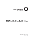
4 In addition to the options you may have ordered, the box
should contain the following:
• Intermec EasyCoder PD41 printer
• Power supply adapter with either one power cord for
115V U.S. wall sockets or two different power cords for
230V European and 240V U.K. wall sockets
• USB cable
• Empty ribbon core (for thermal transfer printing)
• High Media Edge Guide
• Quick Start Guide
• A PrinterCompanion CD containing software, this and
other related manuals.
If you find any damage has occured during transportation, notify
the carrier immediately. If the delivery is missing parts or is
otherwise incorrect, report it to the distributor.
EasyCoder
PD41
Power cable
High media
edge guide
EU
UK
US
USB cable
EasyCoder PD41 Printer User’s Guide
Printer
Companion CD
Empty
ribbon core
3
Chapter 1 — Getting Started
The discharge of electrostatic energy accumulated
on the human body, clothing, or other surfaces can
damage or destroy the printhead or electronic
components used in this printer. Avoid touching
the electrical connectors while unpacking and
setting up the printer.
Product Identification
The machine and serial number labels are attached to the
printer’s rear plate, and contain information on type, model and
serial number as well as AC voltage and frequency.
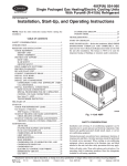
Front View
Side door
Control
LEDs
Print
Button
EasyCoder PD41: Front view
4
EasyCoder PD41 Printer User’s Guide
Chapter 1 — Getting Started
Controls and Indicators
Front panel: LEDs and Print button.
The blue button on the front panel is the Print button, which
also functions as a control button in Testmode. The significance
of each of the four LEDs surrounding the Print button is
described in the table below. A more complete description of the
LEDs can be found in Chapter 2.
Control LEDs
LED name
Light Color Symbol Function
Power
Green
Power indicator.
Ready/Data
Green
Printer ready.
Error
Red
Error indicator.
Ready-to-Work™ Blue
EasyCoder PD41 Printer User’s Guide
Intermec Ready-to-Work™
indicator.
5
Chapter 1 — Getting Started
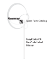
Rear View
Intake for
external
media supply
Side door
Machine
labels
EasyCoder PD41: Rear View
Connectors
Ethernet RJ-45 connector
USB port
MAC address label
Serial RS-232 port
Parallel IEEE 1284 port
I
O
Compact Flash slot
Power On/Off switch
AC power cord socket
Rear view: Connection sockets
6
EasyCoder PD41 Printer User’s Guide
Chapter 1 — Getting Started
Media Compartment
Ink position lever
Edge guide
Media supply post
Ribbon supply shaft
Ribbon rewind shaft
EasyCoder PD41: Media Compartment
Print Mechanism
Ribbon
rod
Label taken
sensor
Media
feed
rods
Printhead
balance boxes
Tear bar
Thermal printhead
Printhead
lever
EasyCoder PD41: Print Mechanism
EasyCoder PD41 Printer User’s Guide
7
Chapter 1 — Getting Started
Installing the Printer
Plugging in the Printer
1 Make sure the Power Switch is turned off.
2 Connect the power cable to the printer.
3 Plug the power cable into your electrical outlet.
3
1
2
Connecting the Printer to your System
The EasyCoder PD41 is fitted with a USB Type B connector for
the USB interface port and one 9-pin D-style subminiature
(DB9) socket for the RS-232 serial interface port. In addition to
this the printer is, depending on configuration, fitted with a 36pin Centronics socket for the parallel (IEEE 1284) port and/or
an RJ-45 socket for the Ethernet network connection.
Information on the socket and connector types can be found in
Appendix D, “Interfaces.”
8
EasyCoder PD41 Printer User’s Guide
Chapter 1 — Getting Started
Connecting the Printer through the USB interface
In order to use the USB connection, you need to install the
Intermec InterDriver software on your computer. This can be
found on the PrinterCompanion CD along with instructions on
how to install it. The USB interface is not suitable for terminal
connections and thus not for programming.
Connecting the Printer to a Network
The printer is set to automatically receive an IP number from the
network (DHCP). The blue Ready-to-Work LED is lit steadily if
the printer has been succesfully connected to the network. The IP
number will be printed on the test label (see next section on how
to print test labels), which can be used to check the printer’s
settings on the printer home page. This is accessed by entering
the printer’s IP number in the adress field of your web browser,
for example http://255.255.255.001
If your network does not assign IP numbers automatically, or the
Ready-to-Work indicator is flashing to indicate a network error,
you can use PrintSet 4 (found on the Printer Companion CD) to
correct the network settings. Alternatively, set up a terminal
connection through the serial interface and use the Fingerprint
SETUP command. See Chapter 5, “Configuring Setup”, or refer
to the Intermec Fingerprint v10.X.X Programmer’s Reference
Manual.
The network connection can be used either with LabelShop or
the Intermec InterDriver. It can also be used to directly send
commands to the printer through a terminal connection, such as
one established through the Windows HyperTerminal program.
In this case, it utilizes the Raw TCP protocol through port 9100.
Connecting the Printer through the Serial Port
The serial connection can be used either with LabelShop or the
Intermec InterDriver. It can also be used to directly send
commands to the printer through a terminal connection, such as
one established through the Windows HyperTerminal program.
The printer’s default serial communication settings are: baud rate
9600, 8 data bits, no parity, 1 stop bit and no flow control. See
Appendix C, “Setup parameters,” for more information.
EasyCoder PD41 Printer User’s Guide
9
Chapter 1 — Getting Started
Connecting the Printer through the Parallel Port
Use the parallel interface (also referred to as“centronics”), with
Intermec LabelShop or the Intermec InterDriver. The parallel
port supports Windows plug-n-play and additional status
reporting through IEEE 1284 nibble ID mode.
Printing a Test Label
In order to verify that the printer is fully functional and to obtain
its current configuration, you can print a test label. This
procedure is part of the Testmode function, described in full in
Chapter 5.
Printing test labels
1 Switch off the printer’s power.
2 Load media as described in Chapter 2, “Loading Media”.
3 Press and hold down the blue Print button.
4 Keep the Print button pressed down, and turn on the power
switch. Do not release the print button until after about ten
seconds when the printer enters Testmode and three of the
front LEDs will start blinking one at a time.
5 The paper type is specified by releasing the Print button at the
cue of different LED flash patterns. In order to establish the
correct media setting, release the Print button at the
appropriate time according to the following table.
Setting the Paper Type
Flashing LED determines
Data/Ready
Green
Media Type
Labels with gap
Error
Red
Tickets with black mark
Ready-to-Work
Blue
Continuos stock
The printer will print several test labels containing the
printer’s setup parameters. It will then enter Dumpmode.
6 Press the Print button once to exit.
10
EasyCoder PD41 Printer User’s Guide
2
Operating the Printer
This chapter explains the basic operation of the printer. You will
learn how to load media for different types of operation and
familiarize yourself with the printer’s control LEDs and the Print
button. This chapter covers the following topics:
• Loading Media
• LED indicators and the Print button
EasyCoder PD41 Printer User’s Guide
11
Chapter 2 — Operating the Printer
Loading Media
The EasyCoder PD41 can print on labels, tickets, tags and
continuous stock in various formats.
Tear-Off (straight-through) Operation
This section describes the case when media is torn off manually
against the printer’s tear bar. This method is also known as
“straight-through” printing. Different sorts of media can be used
in Tear-Off operation:
• Non-adhesive continuous stock
• Self-adhesive continuous stock with liner
• Self-adhesive labels with liner
• Tickets with gaps, with or without perforations
• Tickets with black marks, with or without perforations
Tear-Off
1
2
1
2
Open the side door.
12
Pull out the printhead lever and turn
it counterclockwise.
EasyCoder PD41 Printer User’s Guide
Chapter 2 — Operating the Printer
Tear-Off, continued
3
4
Lift the label feed guide.
Load a media roll onto the media
supply hub, pushing it all the way in.
5
6
Lock the position of the media roll
with the media edge guide.
Guide the media through the rods.
EasyCoder PD41 Printer User’s Guide
13
Chapter 2 — Operating the Printer
Tear-Off, continued
7
8
Route the media through the print
mechanism.
If using fan-fold media, load it
through the rear intake and route the
media the same way as a media roll.
9
10
Reset the label feed guide and the
printhead lever.
Close the side door. Press the Print
button to advance the media.
14
EasyCoder PD41 Printer User’s Guide
Chapter 2 — Operating the Printer
Peel-Off (Self-Strip) Operation
This section describes the case when self-adhesive labels are
separated from the liner immediately after printing. The same
procedure is followed when installing media for Batch Takeup,
with the difference that both label and liner is rewound, and the
label-taken sensor is not used. These modes of operation require
an optional internal rewinder unit, see Appendix E, “Options.”
This is also known as self-strip operation. The label-taken sensor
can hold the printing of the next label in a batch until the present
label has been removed. Only self-adhesive labels with liner can
be used in peel-off operation.
Peel-Off
1
2
Remove the front cover.
Open the cover, mount the media roll,
and route the media through the
media feed rods.
EasyCoder PD41 Printer User’s Guide
15
Chapter 2 — Operating the Printer
Peel-Off, continued
3
4
Route the liner through the print
mechanism and back as shown
above.
Wrap the liner on the liner takeup roll
and lock it in place.
5
6
Reset the label feed guide and the
printhead lever.
Reattach the front cover.
16
EasyCoder PD41 Printer User’s Guide
Chapter 2 — Operating the Printer
Peel-Off, continued
7
8
Push in the location indicated above Turn the Label-Taken Sensor (LTS) to a
to bring out the label-taken sensor.
fully horizontal position.
9
10
Close the side door.
Press the Print button to feed the
media.
EasyCoder PD41 Printer User’s Guide
17
Chapter 2 — Operating the Printer
Loading Thermal Transfer Ribbon
Thermal transfer printing makes it possible to use a wide range of
receiving face materials and gives a durable printout that is less
vulnerable to fat, chemicals, heat, sunlight etc than direct thermal
printing. Make sure to select a ribbon type that matches the type
of receiving material and set up the printer accordingly.
The EasyCoder PD41 can use transfer ribbon rolls wound with
the ink-coated side facing either outward or inward.
The ribbon is normally loaded in conjunction with a new media
roll. For clarity, however, the illustrations below do not show the
media roll. See the previous sections for information on how to
load media for your type of operation.
Loading Ribbon
1
2
1
2
Open the side door.
18
Pull out the printhead lever, and turn
it counterclockwise.
EasyCoder PD41 Printer User’s Guide
Chapter 2 — Operating the Printer
Loading Ribbon, continued
3
4a
Push the ribbon roll onto the right
ribbon hub, and the empty ribbon
core on the left hub.
In case you are using ink-out ribbon,
route the ribbon as shown here.
4b
5
In case you are using ink-in ribbon,
route the ribbon as shown in this
figure.
Move the ink-position lever to the left
for ink-out ribbon, and to the right for
ink-in ribbon.
EasyCoder PD41 Printer User’s Guide
19
Chapter 2 — Operating the Printer
Loading Ribbon, continued
6
Reset the printhead lever to its
original position. Close the side door.
20
EasyCoder PD41 Printer User’s Guide
Chapter 2 — Operating the Printer
LED indicators and the Print Button
The PD41 printer can be in the following “states”, which indicate
its current mode of operation.
PD41 Printer States
State
Power Off
Upgrading
TestMode
Extended TestMode
PUP
Idle
Application running
Printing
Printing (wait for LTS)
Paused
Error
Explanation
Firmware is being upgraded.
See Chapter 5 for description.
See Chapter 5 for description.
Power-UP (starting up)
Waiting for label-taken sensor to indicate
that label has been taken.
Paused during print job
Error state
LED indicators
The four LED indicators will be turned on, off or flash
depending on which state the printer is in. The Power LED will
always be lit for all states except Power Off.
The blue Ready-to-Work LED shows the operational status of the
printer. In simple terms, it is lit when the printer is operational.
When the Ready-to-Work indicator is turned off, or flashes, it
indicates that the printer is not fully operational. There are a
number of conditions that can cause this behaviour; refer to
Chapter 4, “Troubleshooting” for a detailed explanation. It can
also flash when in Testmode or Extended Testmode, see
“Running Testmode” in Chapter 5.
The red Error LED will be lit or flash when an error condition
has occured. This will also cause the Ready-to-Work LED to flash
or turn off.
EasyCoder PD41 Printer User’s Guide
21
Chapter 2 — Operating the Printer
The green Ready/Data indicator will be turned on, off or flash
depending on the printer’s current state. The behavior of the
green Data/Ready and red Error LEDs is shown in the table
below.
Ready/Data and Error LED behavior
State
Ready/Data
Error
Power Off
Upgrading
Testmode
Extended Testmode
PUP
Idle
Application running
Printing
Printing (wait for LTS)
Paused
Error
Off
Off
LEDs turned on one after the other.
See Chapter 5 for description.
See Chapter 5 for description.
On
Off
On/Flash1
Off
On
Off
On/Flash1
Off
Quick flashes2
Off
Flash3
Off
Off
On / Flash4
Footnotes on flashing LED behavior:
1 Flashing with 50% duty ctycle, 0.8 second period when receiving
data, synchronized with Ready-to-Work LED.
2 Two fast flashes, 1.6 second period.
3 Flashing with 50% duty cycle, 0.8 second period, not sycnhronized
with Ready-to-Work LED.
4 Error LED will be lit for Out of Paper, Out of Ribbon, Head
Lifted, Cutter Error and Testfeed not Done conditions. Will flash
as (2), when thermal printhead is too hot. Will flash as (3) for
other error conditions caught by the Direct Protocol error handler.
Print Button
The Print button has different functionality depending on the
printer’s state. Different actions can be specified by pressing the
button less than and more than one second respectively.
22
EasyCoder PD41 Printer User’s Guide
Chapter 2 — Operating the Printer
Print Button function
State
Power Off
Upgrading
Testmode
Extended
Testmode
Idle
Application
running
Printing
Paused
Error
Button pressed < 1 s
Button pressed > 1 s
No action
No action
See “Running Testmode” in Chapter 5
See “Running Testmode” in Chapter 5
Formfeed/Printfeed
Testfeed
Defined by application
Pause print job
Continue print job
Cancel print job
See Chapter 4, “Troubleshooting”
EasyCoder PD41 Printer User’s Guide
23
Chapter 2 — Operating the Printer
24
EasyCoder PD41 Printer User’s Guide
3
Maintaining the
Printer
This chapter explains basic maintenance of the printer. By
following the instructions in this chapter you avoid common
problems, and increase the lifetime of your printer. This chapter
covers the following topics:
• General Maintenance Advice
• Printhead Cleaning
• Internal Cleaning
• External Cleaning
EasyCoder PD41 Printer User’s Guide
25
Chapter 3 — Maintaining the Printer
General Maintenance Advice
In order to attain optimal productivity and a long life for your
EasyCoder PD41, it is recommended that you regularly inspect
the printer and its operation environment to ensure the printer is
operated correctly.
Read the EasyCoder PD41 Safety Instructions for basic operational
safety requirements. Keep the printer in a dry area, away from
larger electrical motors, welders and similar which might affect
printer operation.
Clean you printer regularly, as described in the procedures below,
in order to maintain the quality of your labels and extend the life
of your printer.
Always unplug the power cord before cleaning the
printer.
Printhead Cleaning
Cleaning the printhead on a regular basis is important for the life
of the printhead and to maintain high printout quality. You
should clean the printhead using cleaning cards or a cotton swab
moistened with isopropyl alcohol, preferably each time you load
a new supply of transfer ribbon.
Isopropyl alcohol [(CH3)2CHOH] is a highly
flammable, moderately toxic, and mildly irritating
substance.
Cleaning the printhead
1 Open the side door.
2 Remove the media and ribbon.
3 Pull out the printhead lever and flip it counterclockwise a
quarter of turn.
26
EasyCoder PD41 Printer User’s Guide
Chapter 3 — Maintaining the Printer
4 Use a cleaning card or a soft cotton swab moistened with
isopropyl alcohol to dissolve any contamination on the line of
heat-emitting dots at the front/bottom of the printhead.
5 Wait 30 seconds and carefully rub off any contamination.
Repeat if necessary.
Never use any hard or sharp tools to peel away
stuck labels or similar,. The printhead is delicate
and can easily be damaged.
6 Allow the printhead to dry for a minute or more before
loading a new supply of media and ribbon.
Internal Cleaning
Regular cleaning of the printer’s media compartment ensures
smoother printing operation and avoids problems with media
jams.
Use a soft cloth moistened with isopropyl alcohol to clean the
inside of the printer. Be sure to keep the following parts clean:
• Drive roller and tear bar.
• Media edge guides and media path.
• Label sensors.
Isopropyl alcohol [(CH3)2CHOH;CAS67-63-0] is
a highly flammable, moderately toxic, and mildly
irritating substance.
If there are stuck labels, or adhesive residue from labels, peel as
much as possible with your fingers, and then use isopropyl
alcohol to dissolve the remaining adhesive.
External Cleaning
Making sure to keep the printer clean externally will reduce the
risk of dust or foreign particles reaching the inside of the printer
and affect printer functionality.
EasyCoder PD41 Printer User’s Guide
27
Chapter 3 — Maintaining the Printer
Use a soft cloth, possibly moistened with water or a mild
detergent when cleaning the printer externally. Make sure to keep
the surface surrounding the printer clean as well.
If the printer is used in an environment where the
premises are cleaned by a water hose or steam,
move the printer to another room or cover it very
carefully with a plastic sheet and make sure that the
power cord is unplugged.
28
EasyCoder PD41 Printer User’s Guide
4
Troubleshooting
This chapter helps to diagnose problems that may occur during
printer operation and how to resolve them. This chapter covers
the following topics:
• Printer Operation Problems
• Print Quality Problems
• Troubleshooting Adjustments
EasyCoder PD41 Printer User’s Guide
29
Chapter 4 — Troubleshooting
Printer Operation Problems
The following table lists possible problems that affect the
printer’s operation.
Printing Operation Problems
Problem
Solution / Reason
The Power control LED is • Check that the power cable is correctly
not lit when power is
connected to printer and electrical
switched on.
outlet.
Error LED turns solid red • Check if printer is out of media or
after printing.
ribbon.
• Check if media is jammed or tangled.
• Check that the print mechanism is
locked and closed correctly.
• Check the cutter.
• Check application.
Label is jammed after
• Clear the media jam. If the label is
printing.
stuck on the thermal printhead, clean
as instructed in Chapter 3.
When printing, labels are • Run a new testfeed by holding print
skipped.
button more than one second.
• Check if label gap sensor is disturbed
by dust or foreign particles.
When using cutter, label • Check whether the media thickness
was not cut straight.
exceeds 0.25mm (9.8 mils).
• Check if the media is loaded correctly.
When using cutter, label • Check that the cutter is installed
could not feed or
properly.
abnormal cutting occurs. • Check if paper feed rods are sticky.
Clean as described in Chapter 3.
Blue Ready-to-Work LED • See section later in this chapter
blinks.
regarding the Ready-to-Work LED.
When using internal
• Check that media is loaded correctly.
rewinder, abnormal
function occurs.
Printer keeps printing or • Check media settings.
feeding when it should
• Check label gap sensor position.
stop.
• Sensors may be dirty.
Printing is slow.
• Check application.
30
EasyCoder PD41 Printer User’s Guide
Chapter 4 — Troubleshooting
Print Quality Problems
Print Quality Problems
Problem
Solution / Reason
Printout is faded or weak
• Check the media settings: Constant,
Factor and Contrast.
• Check if printhead needs cleaning.
• Check printhead pressure.
• Check printhead dotline position.
Printer is working but
• Check if media is placed upside down.
nothing is printed
• Ensure that the ink-side of the ribbon
faces the media.
• Select the correct media type, direct
thermal or thermal transfer printing.
• Check that the printhead is correctly
connected to the print mechanism.
Only partial labels are
• Check printhead balance. See later in
printed
this chapter.
Part of the images is not • Check if printhead needs cleaning.
printed along the feed
• Check that the ribbon does not
direction
wrinkle, and follow instructions on
ribbon adjustments in this chapter.
Printout darkness is
• Check printhead balance.
uneven across media path • Check printhead pressure.
Printout is not in desired • Check for errors in printing software
position
application.
• Check if label gap sensor is disturbed
by media, dust or ribbon.
• Check the lateral position of label gap
sensor.
• Check the edge guide and media guide.
• Check the media (insufficient
transparency, interfering preprint lines
in black mark operation, etc.)
• Check if platen roller needs cleaning or
replacement.
EasyCoder PD41 Printer User’s Guide
31
Chapter 4 — Troubleshooting
Ready-to-Work™ Indicator
The blue Ready-to-Work LED is lit when the printer is
operational. It can be turned off or flash in case something is not
working as expected.
Ready-to-Work LED Flashing or Off
The Ready-to-Work indicator is set to flash when the printer is
receiving data, as well as under several different error conditions.
Normally, this is due to an IP link error, where the printer has a
network card but has not yet received an IP number. Other
causes may be that the printhead is lifted, or the media is loaded
incorrectly. The Ready-to-Work LED will be turned off if the
printhead temperature is too high. An error diagnosis can be
obtained with the command SYSHEALTH$. Enter the line PRINT
SYSHEALTH$ through a terminal connection to receive the
printer’s Ready-to-Work status.
Troubleshooting Adjustments
This section describes in detail some of the solutions mentioned
in the Troubleshooting tables above.
Ribbon Wrinkling Adjustments
The follwing two procedures can solve ribbon wrinkling
problems.
Ribbon Tension Adjustment
1 Push the knob on the ribbon supply hub.
2 Rotate it clockwise to increase breaking force or
counterclockwise to decrease breaking force.
Ribbon tension adjustment
32
EasyCoder PD41 Printer User’s Guide
Chapter 4 — Troubleshooting
Ribbon Shield Adjustment
The ribbon shield mechanism is located on the thermal
printhead. It has two adjustable screws, A and B, as shown below.
A
B
Ribbon shield adjustment screws
If the label printout matches Test label A, turn screw A
clockwise. If the printout matches Test label B, turn screw B
clockwise. Turn the screw half a circle and perform a new test
printing. Continue until you achieve a smooth printout quality.
Screw adjustment must not exceed two full turns or paper may
not feed smoothly. In such a case, turn the screws
counterclockwise completely and start over the adjustment.
Test Label A
Test Label B
1234567890 1234567890
Possible printouts due to ribbon wrinkling
Clearing Media Jams
Clearing Media Jam in Print mechanism
1 Switch off the power to the printer.
2 Pull the printhead lever out and turn it counterclockwise to
lift the printhead.
3 Pull out the media from the print mechanism.
If the media has been wound up or is stuck on the platen
roller, carefully remove it by hand without using any sharp
EasyCoder PD41 Printer User’s Guide
33
Chapter 4 — Troubleshooting
tools that can damage the platen roller or printhead. Avoid
rotating the platen roller.
Take care to avoid causing the platen roller to
rotate. The electronic components may be
damaged permanently.
4 Cut off any damaged or wrinkled part of the media.
5 Check to see if there is any adhesive somewhere in the print
mechanism. If so, follow the cleaning instructions in the
section “Internal Cleaning” in Chapter 3.
6 Reload the media as described in Chapter 2.
7 Switch on the power.
8 Readjust the media feed by pressing the Print button.
Printhead Adjustments
A correctly adjusted printhead is crucial for obtaining optimal
printout quality.
Adjusting Printhead Balance
The printer is factory-adjusted for full-size media width. When
using media less than full-width, it is recommended that you
adjust the position of the printhead balance boxes in order for the
printhead to be equally pressured against full media width.
Printhead balance might be poorly adjusted if the printout is
weaker on one side of the media path.
To adjust the printhead pressure, follow these steps:
1 Open the side door.
2 If transfer ribbon has been installed, remove it.
3 Lift the printhead by pulling the printhead lever out and
flipping it a quarter of a turn counterclockwise.
4 Move the balance box on the right side (outer) top the right
(outward) for wider media, and inwards (to the left) for
narrower media.
34
EasyCoder PD41 Printer User’s Guide
Chapter 4 — Troubleshooting
Balance
box
5 Engage the printhead and load the ribbon.
6 Test and readjust if necessary. (Tip: Use direct thermal media
to avoid loading and unloading of ribbon multiple times.)
Adjusting Printhead Pressure
The pressure of the thermal printhead against the platen roller is
factory-adjusted. However, if the printing is weaker on one side
of the media, or if the thermal transfer ribbon starts to crease
(indicated by unprinted white streaks along the media feed
direction), it may be necessary to readjust the printhead pressure.
Note: Before readjusting the printhead pressure, try
the to move the outer balance box as described in
Adjusting Printhead Balance procedure.
1 Open the side door.
2 Remove the ribbon.
3 Lift the printhead by pulling the printhead lever out and
flipping it a quarter of a turn counterclockwise.
4 Use a straight-slot screwdriver to turn the screw at the top of
the balance boxes clockwise to increase the pressure, or
counterclockwise to decrease the pressure.
EasyCoder PD41 Printer User’s Guide
35
Chapter 4 — Troubleshooting
5 Engage the printhead and load the ribbon.
6 Test and readjust if necessary. (Tip: Use direct thermal media
to avoid loading and unloading of ribbon multiple times.)
Adjusting Printhead Dot Line
When using thick or stiff media, the printhead needs to be
moved forward so the dot line is aligned precisely with the top of
the platen roller. They must of course be perfectly parallel as well.
1 Open the side door.
2 Remove the ribbon and engage the printhead.
3 Use a straight-slot screwdriver to turn the two screws at the
top of the printhead bracket counterclockwise a single turn.
4 Lift the printhead by pulling the printhead lever and flipping
it counterclockwise a quarter of a turn.
5 Carefully turn both screws at the front of the printhead
clockwise a quarter of a turn at a time (a full turn
corresponds to 0.55 mm, which is a lot). Make sure to make
identical adjustments on both screws. If you are unsure,
36
EasyCoder PD41 Printer User’s Guide
Chapter 4 — Troubleshooting
tighten both screws completely by turning them
counterclockwise as far as they go and start over.
6 Engage the printhead and lock the printhead by tightening
the two screws at the top of the printhead bracket, that is, the
reverse action of step 3.
7 Load the ribbon (if any).
8 Test and readjust if necessary. (Tip: Use direct thermal media
to avoid loading and unloading of ribbon multiple times.)
Label Gap Sensor Adjustments
The label gap/black mark sensor (also called Label Stop Sensor LSS) is a photoelectric sensor that controls the printer’s media
feed by detecting gaps between labels, or slots or black marks in
continuous stock. This requires the label gap sensor to be aligned
with the gaps, slots or marks on the media. If you are using
irregularly shaped labels, align the sensor with the front tip of the
labels.
Adjusting Label Gap Sensor Position
1 Use the lever at the rear side of the print mechanism to move
the sensor inward or outward.
EasyCoder PD41 Printer User’s Guide
37
Chapter 4 — Troubleshooting
Sensor lever
2 Check the point of detection from the front (with the
printhead lifted.)
Point of
detection
38
EasyCoder PD41 Printer User’s Guide
5
Setting up the Printer
The EasyCoder PD41 has many settings that control printer
operation, communication settings, media types and more. This
chapter describes the printer’s startup sequence and explains how
to set or change setup parameters. It also includes a description of
the two Testmodes available, and a guide on firmware upgrading.
This chapter covers the following topics:
• The Printer Startup Sequence
• Changing Configuration Settings
• Running Testmode
• Upgrading Firmware
EasyCoder PD41 Printer User’s Guide
39
Chapter 5 — Setting up the Printer
The Printer Startup Sequence
When switched on, the printer will go through a sequence of
steps in order to decide what settings should be set and what
application (if any) should be started.
Printer Startup Sequence
1 Check for firmware binary on CompactFlash card. If so,
upgrade.
Note: If the CompactFlash contains an earlier
firmware version than one installed in the printer,
the printer’s firmware will be downgraded.
2 Check if printhead is lifted and button is pressed. If so, go to
Extended Testmode, otherwise continue startup with step 3.
3 Check for the presence of a startup file (autoexec.bat), first on
CompactFlash, then on “c/”. If so, run the startup file.
4 Check to see if button is pressed. If so, go to Testmode.
5 Continue Power-Up. Check APPLICATION file in “c/:” for
program file name. If found, run. If empty, go to idle state.
You can thus control the printer’s behavior after startup by
creating an autoexec.bat file and saving it on a memory card or in
the printer’s permanent memory (device “c/”), writing an
application name in the “APPLICATION” name, or choosing to
go into Testmode.
It is recommended to start custom applications by writing the
name of the desired program (“ProgramName.PRG”) in the
APPLICATION file in “c/”. See the Intermec Fingerprint v10.0.0
Programmer’s Reference Manual to learn how to edit and save a
file to the printer.
Starting a custom application can also be done by creating a
startup file (autoexec.bat) which will execute on startup. This file
must contain Fingerprint commands that are interpreted
immediately. Normal commands are LOAD and RUN. See the
Intermec Fingerprint v10.0.0 Programmer’s Reference Manual to
learn how to create and save such a file to the printer.
The process of entering and using Testmode and Extended
Testmode is described later in this chapter.
40
EasyCoder PD41 Printer User’s Guide
Chapter 5 — Setting up the Printer
Changing Configuration Settings
The complete list of setup options can be found in Appendix C.
Depending on the communication method you use with your
printer, you can set configuration settings with different
methods.
Using PrintSet 4
The recommended way to set your printer’s configuration is to
use the included PrintSet 4 program. PrintSet 4 can
communicate with your printer either via a serial cable or a
network connection. You will find PrintSet 4 on the Printer
Companion CD, and on the Intermec website. This printer
configuration program works on Windows (2000 and XP)
computers, and allows you to easily change all of the setup
parameters. It also includes setup wizards, which guide you
through common configuration tasks.
Using the Printer’s Home Page
If you have a network option and the printer is available on the
network, you can browse to the printer’s home page: Just enter
the printer’s IP number in your browser’s adress field. There you
can enter the configuration page and change the settings. You
will need the printer’s administrator username and password.
Using the Command Line
You can change setup parameters by sending Fingerprint
commands directly through your terminal program (either
through serial or network connection). The Fingerprint
command to use is SETUP, and should be followed by the node
and its values you want to set. For example:
SETUP “MEDIA,MEDIA TYPE,LABEL (w GAPS)”
The SETUP is used to both write and read setup parameters. It
can also be used with setup files in which all configuration
parameters are set. For more information on how to use the
SETUP command, see the Fingerprint v10.X.X Programmer’s
Reference Manual.
EasyCoder PD41 Printer User’s Guide
41
Chapter 5 — Setting up the Printer
Running Testmode
You can check certain settings, print a test label, or enter the
dump mode for troubleshooting purposes by using the printer
testmodes. Two testmodes are available, Testmode and Extended
Testmode.
Testmode
Normal testmode is used to select the media type, to print test
labels, and to enter dump mode. Testmode is entered by pressing
the Print button while switching the printer’s power on. This
starts the Testmode which will go through a sequence of actions;
these can be controlled by pressing the Print button at the cue of
different LED flash patterns. The sequence of steps in testmode is
shown in the tables below:
Testmode: Activating
Data/
Step Ready
Error
RtW
1
2
Button Comment
1
1
1
Make sure the printhead
lever is lowered. Press and
hold the Print button and
switch the printer On.
Testmode is activated after
10 seconds.
LEDs flash fast one at a time.
Keep button pressed.
1
Testmode: Selecting Media Type
Data/
Step Ready Error
3
RtW
Button Comment
3a
3b
3c
4
Release the button when LED corresponding to your media
type flashes
1
0
Labels with gaps.
1
0
Ticket with mark.
1
0
Variable length strip.
The printer will automatically perform a sensor calibration
(Testfeed) according to your selection, and will select thermal
transfer printing if ribbons is installed, otherwise direct thermal.
42
EasyCoder PD41 Printer User’s Guide
Chapter 5 — Setting up the Printer
Testmode: Printing Test Labels
Data/
Step Ready Error
5
RtW
Button Comment
The printer will then print four test labels after the testfeed in
step 4. To skip any test labels tap the button.
Testmode: Running the Dump mode
Data/
Step Ready Error
6
7
8
RtW
Button Comment
The printer is now in Dumpmode and the printer scans the
communication ports. The printer will print any characters it
received on the communication ports to a label when exiting
dump mode.
Tap the button once to exit Dumpmode. If you tap the button
within two seconds of entering dump mode, no labels are
printed.
1
1
The printer will start as on
rebooted status. When
operational, Data/Ready
and RtW will be lit.
Extended Testmode
The extended testmode can be used to run additional tests. This
includes the option to print test labels, running a testfeed in slow
mode, entering dump mode and resetting to factory defaults. The
extended Testmode is entered by raising the printhead, and
switching power on while keeping the Print button pressed.
Extended Testmode will run a sequence which can be controlled
via the Print button, and raising or lowering the printhead. The
sequence of steps in the Extended Testmode follows in the table:
EasyCoder PD41 Printer User’s Guide
43
Chapter 5 — Setting up the Printer
Extended Testmode: Activating
Data/
Step Ready
Error
RtW
1
2
Button Comment
1
flash
flash
Make sure the printhead is
lifted. Press and hold the
Print button and switch the
printer On. Extended
Testmode is activated after
10 seconds.
All 3 LEDs flash rapidly four
times. Extended Testmode is
activated. Release button to
continue.
flash
Extended Testmode: Selecting Function
Data/
Step Ready Error
RtW
Button Comment
3
flash
0
4
5
6
7a
7b
7c
7d
7e
flash
flash
LEDs flash fast four times,
in four-second intervals.
flash
Lower the printhead.
1
Press the Print button and
hold.
Release the button when LED combination corresponding to
your choice of function flashes. Then see corresponding
function table below.
0
0
1
Test Label function.
0
1
0
Testfeed Mode Slow
function.
0
1
1
Dump mode function.
1
0
0
Factory default function.
1
1
1
Exit Extended Testmode.
The functions 7a-7e are described on the next page.
44
EasyCoder PD41 Printer User’s Guide
Chapter 5 — Setting up the Printer
Extended Testmode: 7a - Test Label Function
Data/
Step Ready Error
RtW
7a
1
Button Comment
LED flashes once per
second.
1
Tap the Print button, once
for each of 7test labels.
Press Print button and hold it to exit Test Label function and return to
Step 6.
Extended Testmode: 7b - Testfeed Mode Slow Function
Data/
Step Ready Error
7b
RtW
Button Comment
1
LEDs flash once per
second.
1
Tap the Print button to
start Testfeed (Mode slow).
Test label is printed.
1
LED flashes once per
second.
Press Print button and hold it to exit Testfeed Mode Slow function,
and return to step 6.
Extended Testmode: 7c - Dumpmode Function
Data/
Step Ready Error
RtW
7c
1
1
Button Comment
LEDs flash once per
second.
1
Tap the Print button to
start Dumpmode.
The printer will autohunt the communucation ports.
Tap the button to exit.
Press >1 second to save dumpmode info.
1
1
Leds flash once per second.
Press button and hold it to exit this function and return to Step 6.
EasyCoder PD41 Printer User’s Guide
45
Chapter 5 — Setting up the Printer
Extended Testmode: 7d - Factory Default Function
Data/
Step Ready Error
7d
RtW
Button Comment
1
LEDs flash once per
second.
Lift the printhead, tap the Print button, and lower the printhead.
LEDs will flash.
Tap the button. Printer will start resetting to factory defaults. This is
indicated by scrolling LEDs.
1
LED flashes once per
second, indicating factory
default reset is done.
Press the button > 1 second to perform testfeed. When done, printer
will be ready for use (out of Testfeed mode.)
Extended Testmode: 7e - Exit
Data/
Step Ready Error
RtW
Button Comment
7e
1
1
LEDs flash once per
second.
1
Tap the Print button to exit
Extended Testmode.
The LEDs flash rapidly, and printer is ready for use.
46
1
1
EasyCoder PD41 Printer User’s Guide
Chapter 5 — Setting up the Printer
Upgrading Firmware
The www.intermec.com web site contains the latest software that
you can download for free.
To download firmware updates
1 Visit the Intermec web site at www.intermec.com.
2 Click Service & Support > Downloads.
3 In the Select a Product field, choose the EasyCoder PD41
and you will be presented with the latest software available.
4 Download the latest firmware version to your computer.
5 Extract the zip file to a folder on your computer. Normally,
three versions of the firmware are included with the following
differences and naming convention:
• No suffix: Normal firmware upgrade.
• FD suffix: Firmware upgrade resetting Factory Default.
Only applicable when upgrading through a Compact
Flash card.
• NU suffix: Boots with new firmware, yet printer returns to
previous firmware version on reboot (No Upgrade). Only
applicable when upgrading through a Compact Flash
card.
To upgrade the downloaded firmware to your printer, use any one of the
following methods:
• Use PrintSet 4 and follow the firmware upgrade procedure.
• If you have a network connection, browse to the printer’s
home page (see Chapter 2, “Network connection”), and select
Maintenance. Upload the firmware file.
• Copy the firmware binary file to a CompactFlash card. Turn
the printer off, insert the card into the printer’s
CompactFlash socket and switch on the printer. The printer
will be upgraded automatically.
EasyCoder PD41 Printer User’s Guide
47
Chapter 5 — Setting up the Printer
48
EasyCoder PD41 Printer User’s Guide
A
Technical Data
This Appendix lists technical specifications for the EasyCoder
PD41. The appendix contains:
• Table of Printer Specifications.
EasyCoder PD41 Printer User’s Guide
49
Appendix A — Technical Data
Printer Specifications
Printer Specifications Table
Physical Dimensions
Dimensions (WxLxH) 276 x 454.4 x 283.0 mm
(10.85 x 17.9 x 11.2 inches)
Weight (excl. media)
13 kg (28.7 pounds)
Power Supply
Input Rating
Power Consumption
100-240 VAC, 3-1 A, 50-60 Hz
• Stand-by : 12W
• Normal operation/printing: 80W
• Peak: 250W
Printing
Print Technique
Printhead Resolutions
Print Speed
8 dots/mm (203 dpi)
11.8 dots/mm (300dpi)
Print Width Max.
8 dots/mm (203 dpi)
11.8 dots/mm (300dpi)
Print Length Max.
8 dots/mm (203 dpi)
11.8 dots/mm (300dpi)
Direct Thermal/Thermal Transfer
8 dots/mm (203.2 dpi) or
11.81 dots/mm (300dpi)
50.8 to 152.4 mm/sec . (2 to 6 in./sec.)
50.8 to 101.6 mm/sec. (2 to 4 in./sec.)
104 mm (4.09 in.)
105.7 mm (4.16 in.)
1270 mm (50 in.)
558.2 mm (22 in.)
Modes of Operation
Tear-Off (Straightthrough)
Cut-off
Peel-Off (self-strip)
Yes
Option with cutter
Option with internal
rewinder
Firmware
Operating System
Fingerprint v10.0.X
Smooth Fonts
TrueType and TrueDoc fonts
50
Includes Direct
Protocol
EasyCoder PD41 Printer User’s Guide
Appendix A — Technical Data
Printer Specifications Table
Resident scaleable fonts 15
Character Sets
• 23 single-byte character sets standard.
• UTF-8 support as standard.
Resident Bar Codes
61
Environment
Operating temperature
Storage temperature
Operating Humidity
Storage Humidity
+5°C to +40°C (+41°F to 104°F)
-20°C to 70°C (-4°F to 122°F)
20 to 80% non-condensing
10 to 90% non-condensing
Media
Media width
Media Roll diameter
Internal Rewinder
diameter
Media Roll Core
Diameter
Media Thickness
25 to 118 mm (1 to 4.65 inches)
Max 114mm (4.49 in.) with cutter.
213 mm (8.35 in.) max.
190 mm (7.5 in.) with internal rewinder.
Max 140 mm (5.51 in.)
38.1 to 76.2 mm (1.5 to 3 in.)
60 μm to 250 μm (2.3 to 9.8 mils)
Transfer Ribbon
Material
Winding
Ribbon width
Ribbon Roll Diameter
(outer)
Inner core Diameter
Wax, hybrid, or resin
Ink on either inside or outside of roll
30 to 110 mm (1.18 to 4.33 in.)
76 mm (2.99 in.) equivalent to 450 meters
(1471 ft) of ribbon.
25.2 to 25.6 mm (1 in.)
Sensors
Label Gap/Black Mark/
Out of Media
Printhead Lifted
Label Taken
Ribbon End
Yes
Yes
Yes
Yes
Controls
LED indicators
Keys
4: Power, Data/Ready, Error, Ready-to-Work
One
EasyCoder PD41 Printer User’s Guide
51
Appendix A — Technical Data
Printer Specifications Table
Electronics
Micropocessor
Standard Memory
ARM 9
4 MB Flash, 8 MB SDRAM.
Interfaces
RS-232 Serial
USB
Ethernet
IEEE 1284 Parallel
CompactFlash
Yes
Yes
Yes/Option
Yes/Option
Yes
Accesories and Options
Internal Rewinder and Batch Takeup
Cutter
Printhead 203/300 dpi
EasyLAN Ethernet Interface
Parallel IEEE 1284 Interface
52
EasyCoder PD41 Printer User’s Guide
B
Media Specifications
This appendix illustrates the different media types the EasyCoder
PD41 can operate with, and states the allowed dimensions of the
paper, ribbon and rolls. This appendix covers the following
topics:
• Media Roll Sizes
• Paper Types and Sizes
EasyCoder PD41 Printer User’s Guide
53
Appendix B — Media Specifications
Media Roll Sizes
The media roll must comply with the following dimensions:
Media roll dimensions
Core
Diameters:
Width:
38 to 76.2 mm (1.5 to 3 inches)
Must not protrude outside the media.
Internal Roll
Max. diamater
Max diameter with
internal rewinder
Max. width
Max. width with cutter
Min. width
Thickness
212 mm
190 mm
8.35 inches
7.5 inches
118 mm
114 mm
25 mm
60 to 250 μm
4.65 inches
4.49 inches
1.00 inches
2.3 to 9.8 mils
Thicker media may be used, but print quality will be reduced.
the stiffness is also important, and must be balanced against
thickness to maintain print quality.
54
EasyCoder PD41 Printer User’s Guide
Appendix B — Media Specifications
The media supply must not be exposed to sand, dust, grit etc.
Any hard particles, no matter how small, can damage the
printhead.
Ribbon Size
The core of the ribbon must be 25.2-25.6 mm (1 inch), as the
empty ribbon core included in the box. The outer dimensions of
the ribbon roll may be:
Max. diameter
Max. width
Min. width
76 mm
110 mm
30 mm
EasyCoder PD41 Printer User’s Guide
2.99 inches
4.33 inches
1.18 inches
55
Appendix B — Media Specifications
Paper Types and Sizes
Non-Adhesive Strip
a: Media Width
Maximum:
Minimum:
118.0 mm
25.0 mm
4.65 inches
1.00 inches
Paper Type Setup
• Variable length strip
• Fixed length strip
NON-ADHESIVE
STRIP
Non-adhesive strip
56
EasyCoder PD41 Printer User’s Guide
Appendix B — Media Specifications
Self-Adhesive Strip
a: Media Width
Maximum:
Minimum:
118.0 mm
25.0 mm
4.65 inches
1.00 inches
b: Liner
The liner must extend evenly on both sides and not more than a total
of 1.6 mm (0.06) inches outside the face material.
c: Media Width (excluding liner)
Maximum:
Minimum:
116.4 mm
23.8 mm
4.58 inches
0.94 inches
Paper Type Setup
• Variable length strip
• Fixed length strip
SELF-ADHESIVE
STRIP
Self-adhesive strip
EasyCoder PD41 Printer User’s Guide
57
Appendix B — Media Specifications
Self-Adhesive Labels
a: Media Width
Maximum:
Minimum:
118.0 mm
25.0 mm
4.65 inches
1.00 inches
b: Liner
The liner must extend evenly on both sides and not more than a total
of 1.6 mm (0.06) inches outside the face material.
c: Label Width (excluding liner)
Maximum:
Minimum:
116.4 mm
23.8 mm
4.58 inches
0.94 inches
d: Label Length
8 dots/mm (203 dpi)
Maximum:
1270 mm*
Minimum:
6 mm
11.81 dots/mm (300 dpi)
Maximum:
558.8 mm*
Minimum:
6 mm
50 inches
0.2 inches
22 inches
0.2 inches
* This is the print length limit set by memory constraints.
e: Label Gap
Maximum:
Minimum:
Recommended:
26.0 mm
1.2 mm
3.0 mm
1.02 inches
0.05 inches
0.12 inches
The Label Gap sensor must be able to detect the front edges of
the labels. It can be moved 0 to 57 mm (0 to 2.24 inches) from
the inner edge of the media.
Paper Type Setup
• Labels with Gaps
58
EasyCoder PD41 Printer User’s Guide
Appendix B — Media Specifications
a
c
d
e
SELF-ADHESIVE
LABELS
b
b
FEED
DIRECTION
Self-adhesive Labels
EasyCoder PD41 Printer User’s Guide
59
Appendix B — Media Specifications
Tickets with Gaps
a: Media Width
Maximum:
Minimum:
118.0 mm
25.0 mm
4.65 inches
1.00 inches
b: Copy Length
8 dots/mm (203 dpi)
Maximum:
1270 mm*
Minimum:
6 mm
11.81 dots/mm (300 dpi)
Maximum:
558.8 mm*
Minimum:
6 mm
50 inches
0.2 inches
22 inches
0.2 inches
* This is the print length limit set by memory constraints.
c: Detection Position
Variable:
0 to 57 mm 0 to 2.24 inches
d: Detection Slit Length
The length of the detection slit (excluding corner radius) must be
minimum 2.5 mm (0.10 inches) on either side of the detection
position.
e: Detection Slit Height
Maximum:
Minimum:
Recommended:
26.0 mm
1.2 mm
3.0 mm
1.02 inches
0.05 inches
0.12 inches
Paper Type Setup
• Tickets with Gaps
Note: Do not allow any perforation to break the edge
of the media as this may cause the media to split and
jam the printer.
60
EasyCoder PD41 Printer User’s Guide
Appendix B — Media Specifications
a
c
b
e
d
TICKETS & TAGS
FEED
DIRECTION
Tickets with Gaps
EasyCoder PD41 Printer User’s Guide
61
Appendix B — Media Specifications
Tickets with Black Mark
a: Media Width
Maximum:
Minimum:
118.0 mm
25.0 mm
4.65 inches
1.00 inches
b: Copy Length
8 dots/mm (203 dpi)
Maximum:
1270 mm*
Minimum:
6 mm
11.81 dots/mm (300 dpi)
Maximum:
558.8 mm*
Minimum:
6 mm
50 inches
0.2 inches
22 inches
0.2 inches
* This is the print length limit set by memory constraints.
c: Detection Position
Variable:
0 to 57 mm 0 to 2.24 inches
d: Black Mark Width
The detectable width of the black mark should be at least 5.0 mm (0.2
inches) on either side of the Label Gap Sensor detection point.
e: Black Mark Length
Maximum:
Minimum:
Common:
25.0 mm
3 mm
5 mm
0.98 inches
0.12 inches
0.2 inches
f: Black Mark Y-Position
It is recommended that you place the black mark as close to the front
edge of ticket as possible and use a negative Stop Adjust value to
control the media feed, so the tickets can be properly torn off.
Paper Type Setup
• Tickets with Mark
62
EasyCoder PD41 Printer User’s Guide
Appendix B — Media Specifications
Note: Preprint that may interfere with the detection
of the black mark should be avoided.
Note: the black mark should be non-reflective carbon
black on a white or near-white background. Do not
allow any perforations to break the edge of the media
as this may cause the media to split and jam the
printer.
a
b
c
e
d
f
TICKETS
WITH MARKS
FEED
DIRECTION
Tickets with Black Mark
EasyCoder PD41 Printer User’s Guide
63
Appendix B — Media Specifications
64
EasyCoder PD41 Printer User’s Guide
C
Setup Parameters
This appendix lists all of the setup parameters that you can
configure to fit your operating environment. This appendix
covers the following topics:
• Setup Description
• Serial Communication Setup
• Feed Adjust Setup
• Media Setup
• Print Definitions Setup
EasyCoder PD41 Printer User’s Guide
65
Appendix C — Setup Parameters
Setup Description
The printer’s Setup parameters are used to set the printer’s
operational behavior. Chapter 5, “Configuring Settings”,
explains how to set or change the parameters, and this is also
explained in the Fingerprint v10.X.X Programmer’s Reference
Manual, under the SETUP command.
Serial Communication Setup
The serial communication parameters control the
communication between the printer and the connected computer
or other devices on the standard serial port, referred to as
"uart1:".
For the serial communication channel ("uart1:"), the following
parameters can be set. Make sure they match the setup of the
connected device or vice versa. If the setup of the printer and the
setup of the host do not match, the response from the printer to
host will be garbled.
Baud Rate
The baud rate is the transmission speed in bits per second. There
are 10 options:
• 300
• 600
• 1200
• 2400
• 4800
• 9600 (default)
• 19200
• 38400
• 57600
• 115200
66
EasyCoder PD41 Printer User’s Guide
Appendix C — Setup Parameters
Character Length
The character length specifies the number of bits that will define
a character. Eight bits are recommended, since that option allows
more special characters and characters that are used exclusively in
foreign languages. Refer to the Intermec Fingerprint v10.X.X,
Programmer’s Reference Manual for more information.
• 7 (Characters ASCII 000 to 127 decimal)
• 8 (Characters ASCII 000 to 255 decimal). Default.
Parity
The parity decides how the firmware will check for transmission
errors. There are five options:
• None (default)
• Even
• Odd
• Mark
• Space
Stop Bits
The number of stop bits specifies how many bits will define the
end of a character. There are two options:
• 1 (default)
• 2
Flow Control
RTS/CTS is a protocol in which communication is controlled
via currents through separate lines in a cable that are set either to
HIGH or LOW. By default, this option is disabled.
CTS on the Printer is connected to RTS on the PC and vice
versa. CTS HIGH from the printer indicates that the unit is
ready to receive data.
CTS LOW from the printer indicated that the receive buffer is
full (see XON/XOFF). In some computer programs, e.g.
Microsoft Windows HyperTerminal, RTS/CTS is designated
"Hardware."
EasyCoder PD41 Printer User’s Guide
67
Appendix C — Setup Parameters
XON/XOFF is a protocol in which communication is controlled
by the control characters XON (ASCII 17 dec.) and XOFF
(ASCII 19 dec.) transmitted on the same line as the data. XON/
XOFF can be enabled/disabled separately for data received from
the host by the printer (printer sends XON/XOFF) and for data
transmitted to the host from the printer (host sends XON/
XOFF).
New Line
Selects the character or characters transmitted from the printer to
indicate a new line. There are three options:
• CR/LF
ASCII 13 + 10 dec. (default)
• LF
ASCII 10 dec.
• CR
ASCII 13 dec.
Receive Buffer
The Receive buffer stores the input data before processing. The
size is 8192 bytes and cannot be changed.
Transmit Buffer
The transmit buffer stores the input data before processing.
Default size is 8192 bytes and cannot be changed.
Feed Adjust Setup
The Feedadjust part of the Setup Mode controls how much of
the media is fed out or pulled back before and/or after the actual
printing. These settings are global and will be effected regardless
of which program is run.
Note: The firmware uses the front edges of labels with
gaps, the ends of detection slots, and the forward
edges of black marks for detection, all seen in relation
to the feed direction.
Start Adjust
The Start Adjust value is given as a positive or negative number
of dots. Default value is 0, which places the origin a certain
distance back from the forward edge of the copy.
• A positive start adjustment means that the specified length of
media will be fed out before the printing starts. Thus, the
68
EasyCoder PD41 Printer User’s Guide
Appendix C — Setup Parameters
origin is moved further back from the forward edge of the
copy.
• A negative start adjustment means that the specified length of
media will be pulled back before the printing starts. Thus, the
origin is moved towards the forward edge of the copy.
Stop Adjust
The Stop Adjust value is given as a positive or negative number of
dots. Default value is 0, which stops the media feed in a position
suitable for tear off operation.
• A positive stop adjustment means that the normal media feed
after the printing is completed will be increased by the
specified value.
• A negative stop adjustment means that the normal media feed
after the printing is completed will be decreased by the
specified value.
Media Setup
The media parameters tell the firmware the characteristics of the
media that will be used, so that the printout will be positioned
correctly and attain the highest possible quality.
Media Size
The size of the printable area is defined by three parameters; XStart, Width, and Length.
X-Start
Specifies the position of the origin along the dots on the
printhead.
The default X-start value prevents printing outside the labels
when the liner is slightly wider than the labels. If you want to
maximize the print width, reset the X-start value to its default: 0.
By increasing the value for the X-start parameter, the origin will
be moved outwards, away from the inner edge of the media path.
In other words, the larger X-start value, the wider inner margin
and the less available print width.
EasyCoder PD41 Printer User’s Guide
69
Appendix C — Setup Parameters
Width
Specifies the width of the printable area in number of dots from
the origin. Thus, the sum of the X-start and width values gives
the outer margin of the printable area. The width should be set to
prevent printing outside the media, which may harm the
printhead.
Length
Specifies the length of the printable area in number of dots from
the origin along the Y-coordinate and allocates memory space for
two identical image buffers in the printer’s temporary memory.
The size of each buffer can be calculated using this formula:
Buffer size (bits) = [Print length in dots] x [Printhead width in dots]
• The length setup also decides the amount of media feed when
using “fix length strip.”
• The length setup creates an emergency stop, which works
when the printer is set up for “Label (w gaps)”, “Ticket (w
mark)”, or “Ticket (w gaps).” If the label stop sensor has not
detected a gap or mark within 150% of the set length, the
media feed is automatically stopped to avoid feeding out a
whole roll of media, due to sensor malfunction.
By setting up the X-start, the Width, and the Length, you will
create a print window inside which printing can be performed.
Any object or field extending outside the print window in any
direction will either be clipped or cause an error condition (Error
1003 “Field out of label”), see Intermec Fingerprint v10.xx,
Programmer’s Reference Manual.
70
EasyCoder PD41 Printer User’s Guide
Appendix C — Setup Parameters
14 mm (0.55 in)
max. 104.0 mm (4.095 in)
Length
Dot-line
on printhead
Origin
X-start
Dot #0
PRINT
WINDOW
Width (1-832 dots)
FEED
DIRECTION
Dot #831
25-118 mm (1-4.65 in)
Print Window: 8 dots/mm standard printhead
Media Type
The Media Type parameter controls how the label stop sensor
(LSS) and the media feed work. There are five media type
options, see also Appendix B, “Media Specifications”:
• Label (w gaps) is used for adhesive labels mounted on liner.
• Ticket (w mark) is used for labels, tickets, or continuous stock
provided with black marks at the back.
• Ticket (w gaps) is used for tickets and tags with detection slits.
• Fix length strip is used for continuous stock where the length
of the print window decides the length of media to be fed out.
• Var length strip is used for continuous stock. The size of the
print images decides the length of each copy.
It is important to select the correct media type, so the printer can
communicate the following errors.
• Error 1005 “Out of paper” indicates that the last ordered
copy could not be printed because of an empty media stock.
EasyCoder PD41 Printer User’s Guide
71
Appendix C — Setup Parameters
• Error 1031 “Next label not found” indicates that the last
ordered label or ticket was successfully printed, but no more
labels/tickets can be printed because of an empty media stock.
Paper Type
The Paper Type parameters control the heat emitted from the
printhead to the direct thermal media or, optionally, the transfer
ribbon in order to produce the dots that make up the printout
image.
Labels, tickets, tags, strip, and ribbons for various types of
application are available from Intermec. To attain optimal
printout quality and extending the life of the printhead, use
Intermec supplies. Heat setting recommendations for Intermec
media can be found from the Intermec website:
www.intermec.com/eprise/main/Intermec/Content/Products/
Products_HeatSettings
As a general rule, high energy and/or high print speed will
shorten the life of the printhead. Never use incorrect paper type
settings or higher print speed settings than necessary for
obtaining an acceptable printout quality and throughput speed.
If the ambient temperature is lower than +15°C (+59°F), decrease
the print speed by 50 mm/sec.
Start by choosing between two alternatives:
• Direct Thermal printing (option)
• Thermal Transfer printing (default)
Note: It is highly recommended to use PrintSet 4 to
set the Paper Type setup parameters. PrintSet 4
includes a Print Quality Wizard that guides you
through the process of improving printout quality.
Your choice will decide which parameters to enter next:
Direct Thermal Printing
• Label Constant (range 50 to 115). Default 85.
• Label Factor (range 10 to 50). Default 40.
The following table gives initial recommendations for suitable
settings.
72
EasyCoder PD41 Printer User’s Guide
Appendix C — Setup Parameters
Direct Thermal Recommmended Settings
Paper
Label
sensitivity Constant
Low
Standard
High
Ultra High
Label
Factor
Max Print
Speed (203
dpi
Max Print
Speed (300
dpi)
40
40
40
40
75
100
125
150
50
75
100
100
100
90
80
70
Use the above settings as initial settings and adjust the Label
Constant if necessary.
Thermal Transfer printing
• Ribbon Constant (range 50 to 115). Default 90.
• Ribbon Factor (range 10 to 50). Default 25.
• Label Offset (range -50 to 50). Default 0.
The following tables gives initial recommendations for suitable
settings.
Thermal Transfer Recommended Settings
Ribbon
Wax
Hybrid
(Wax/Resin)
Resin
Max Print Max Print
Speed (203 Speed (300
dpi
dpi)
Ribbon
Constant
Ribbon
Factor
80
90
20
25
75
100-150
75
75-100
100
30
150
100
The receiving material has been excluded from this table, since
the ribbon has the largest impact for heat settings for thermal
transfer settings.
Use the above settings as initial values, and adjust the Ribbon
Constant if necessary.
EasyCoder PD41 Printer User’s Guide
73
Appendix C — Setup Parameters
Contrast
Use the contrast parameter to make minor adjustments of the
blackness of the printout, for example to adapt the printer to
variations in quality between different batches of the same media.
The options are values between -10% to 10% in steps of 2.
Default value is 0%. The contrast is reset to the default value
whenever a new paper type is specified, regardless which method
has been used.
Testfeed
The Testfeed is a read-only parameter that indicates internal
parameters for the Label Stop Sensor. These are automatically set
when running a Testfeed (by pressing Print button more than
one second.) It is very important to run a testfeed when switching
from one media type to another.
Testfeed Mode
In certain unusual cases, a Testfeed may have been unable to
succesfully identify gaps or marks in the media. It is thus possible
to set the Testfeed Mode to Slow to allow the Label Stop Sensor
to more easily identify media gaps/marks. The options are Slow
and Fast (default).
LEN (Slow Mode)
When the Testfeed Mode is set to slow, the printer will sample
the media length plus 10mm. You can change the sample length
by specifying the number of dots in LEN(Slow Mode), the
minimum being the number of dots corresponding to 10mm.
The default (media length plus 10mm) is specified by the value 0.
Print Definitions
Print Speed
The Print Speed is specified in mm/second. Allowed values are
50-150 mm/s (2-6 ips) for the 203dpi printhead and 50-100
mm/s (2-4 ips) for the 300 dpi printhead. Default is 100 mm/s
(4 ips) and 75 mm/s (3 ips) for 203 and 300 dpi printheads
respectively.
74
EasyCoder PD41 Printer User’s Guide
D
Interfaces
This appendix describes the default interfaces, as well as the
optional kits that add functionality to your EasyCoder PD41.
This appendix covers the following topics:
• RS-232 Serial Interface
• USB Interface
• EasyLAN Ethernet Interface (Option)
• Parallel IEEE 1284 Interface (Option)
EasyCoder PD41 Printer User’s Guide
75
Appendix D — Interfaces
RS-232 Serial Interface
Protocol
Default Setup
Baud rate
Character length
Parity
Stop bits
Handshaking
9600
8 bits
None
1
XON/XOFF and RTS/CTS
To change the Serial settings, see Chapter 5, “Configuring
Setup”.
Interface cable
The computer end of the cable depends on the computer model.
The printer end is a DB-9pin plug, as shown below.
2
1
6
3
7
4
8
5
9
RS-232 DB9-pins
Signals on the printer’s serial port:
DB-9
1
2
3
4
5
6
7
8
9
76
Signal
Meaning
TXD
RXD
External +5V DC Max 500mA
Transmit data
Receive data
GND
Ground
CTS
RTS
Clear to send
Request to send
EasyCoder PD41 Printer User’s Guide
Appendix D — Interfaces
USB Interface
The printer supports USB v1.1 (also called USB 2.0 full speed).
To use the USB interface to print from a PC, you need to have
the Intermec USB printer driver installed on your PC. You will
find this driver (InterDriver) on the Printer Companion CD
along with installation instructions.
The printer is a so called “self-powered device”. We recommend
that you only connect one printer to each USB port on the host,
either directly or via a hub. Other devices, like a keyboard and a
mouse, can be connected to the same hub. If you need more than
one Intermec USB printer to a host, you should use different
USB ports.
The USB cable included with the EasyCoder PD41 has a USB
Type A connector on one end to connect to a PC, and a USB
TypeB connector to connect to the printer.
There is no communication setup for the USB port.
USB Type A connector (connects to PC or hub)
USB Type B connector (connects to printer)
EasyCoder PD41 Printer User’s Guide
77
Appendix D — Interfaces
EasyLAN Ethernet Interface
The EasyLAN Ethernet interface has an RJ-45 socket for use
with a standard RJ-45 cable. The interface supports 10/100
Mbps Fast Ethernet (10BASE-T, 100BASE-TX) and is fully
compliant to the IEEE 802.3u standard. The network card MAC
adress can be found on the label below the socket.
Network status LEDs
Ethernet RJ-45
connector
Ethernet RJ-45
socket
One yellow and one green LED indicate the network status.
Network Status LEDs
Green On:
Green Off:
Green Blinking:
Yellow Off:
Yellow On:
Link
No link
Activity
10BT
100BT
Parallel IEEE 1284 Interface
The parallel port supports Windows plug-n-play and additional
status reporting through IEEE 1284 nibble ID mode.
Interface cable
Parallel cable compatible with PC.
Pinout Description
Pin
Function
Transmitter
1
2-9
10
11
12
13
nStrobe
Data 0-7
nAcknowledge
Busy
Perror
Select
host
host
printer
printer
printer
printer
78
Comment
EasyCoder PD41 Printer User’s Guide
Appendix D — Interfaces
Pinout Description
Pin
Function
Transmitter
14
15-16
17
18
19-30
31
32
33
34-35
36
nAutoFd
Not connected
Chassis ground
External +5V DC
Signal ground
nInit
nFault
printer
Signal ground
Not connected
nSelectln
EasyCoder PD41 Printer User’s Guide
Comment
Max 500mA
79
Appendix D — Interfaces
80
EasyCoder PD41 Printer User’s Guide
E
Options
This appendix describes the options that add functionality to
your EasyCoder PD41 Printer. For a complete description and
installations instructions, see the respective installation
instructions document for each kit. Please note that several of
these options can only be factory-fitted or installed by an
authorized service technician. This appendix covers the following
topics:
• EasyLAN Ethernet
• Parallel IEEE 1284 Interface
• Cutter
• Internal Rewinder and Batch Takeup
• Printhead Kit (203 or 300 dpi)
EasyCoder PD41 Printer User’s Guide
81
Appendix E — Options
EasyLAN Ethernet Interface
The EasyLAN Ethernet Interface kit adds network capability to
your printer. See “Interfaces” in Appendix D.
Parallel IEEE 1284 Interface
This kit adds a parallel (“centronics”) port to your printer. See
the “Interfaces” in Appendix D.
Cutter Kit
The Cutter is designed to cut off continuous paper-based stock
or liner between labels. The paper cutter can be controlled using
the instructions CUT, CUT ON and CUT OFF in Fingerprint
(and Direct Protocol).
Internal Rewinder
The Internal Rewinder (and Batch Takeup) kit is an optional
device for peel-off (self-strip) operation, which means that the
labels are separated from the liner (backing paper) after printing
and the liner is wound up on an internal hub. It can also be used
to roll up complete batches of label rolls. The unit also includes a
guide shaft. See Chapter 2, “Loading Media”, for instructions on
how to load the media for peel-off operation.
Printhead Kit
The printer can be fitted with either a 203dpi or 300dpi
printhead. These printheads use different PCBs (printed circuit
board?). The printhead kit is thus available as a replacement kit
(printhead only), or as a complete kit (printhead plus PCB).
82
EasyCoder PD41 Printer User’s Guide
Appendix E — Options
EasyCoder PD41 Printer User’s Guide
83
Corporate Headquarters
6001 36th Avenue West
Everett, Washington 98203
U.S.A.
tel 425.348.2600
fax 425.355.9551
www.intermec.com
EasyCoder PD41 Printer User’s Guide
*1-960652-00*
P/N 1-960652-00