1
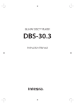
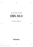
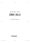
Contents
Seven Channel Amplifier
DTA-9.4
Before using
Instruction Manual
Operations
Connections
Thank you for purchasing the Integra Seven
Channel Amplifier.
Please read this manual thoroughly before making
connections and plugging in the unit. Following the
instructions in this manual will enable you to obtain
optimum performance and listening enjoyment from
your new Seven Channel Amplifier. Please retain this
manual for future reference.
Appendix
En
WARNING:
TO REDUCE THE RISK OF FIRE OR ELECTRIC SHOCK,
DO NOT EXPOSE THIS APPLIANCE TO RAIN OR
MOISTURE.
CAUTION:
TO REDUCE THE RISK OF ELECTRIC SHOCK, DO NOT
REMOVE COVER (OR BACK). NO USER-SERVICEABLE
PARTS INSIDE. REFER SERVICING TO QUALIFIED
SERVICE PERSONNEL.
WARNING
AVIS
RISK OF ELECTRIC SHOCK
DO NOT OPEN
RISQUE DE CHOC ELECTRIQUE
NE PAS OUVRIR
The lightning flash with arrowhead symbol, within an equilateral
triangle, is intended to alert the user to the presence of uninsulated
“dangerous voltage” within the product’s enclosure that may be of
sufficient magnitude to constitute a risk of electric shock to persons.
The exclamation point within an equilateral triangle is intended to
alert the user to the presence of important operating and maintenance
(servicing) instructions in the literature accompanying the appliance.
Important Safeguards
1. Read Instructions – All the safety and operating instructions
should be read before the appliance is operated.
2. Retain Instructions – The safety and operating instructions
should be retained for future reference.
3. Heed Warnings – All warnings on the appliance and in the
operating instructions should be adhered to.
4. Follow Instructions – All operating and use instructions
should be followed.
5. Cleaning – Unplug the appliance from the wall outlet before
cleaning. The appliance should be cleaned only as recommended by the manufacturer.
6. Attachments – Do not use attachments not recommended by
the appliance manufacturer as they may cause hazards.
7. Water and Moisture – Do not use the appliance near water –for
example, near a bath tub, wash bowl, kitchen sink, or laundry
tub; in a wet basement; or near a swimming pool; and the like.
8. Accessories – Do not place the appliance on an unstable cart,
stand, tripod, bracket, or table. The appliance may fall, causing
serious injury to a child or adult, and serious damage to the
appliance. Use only with a cart, stand, tripod, bracket, or table
recommended by the manufacturer, or sold with the appliance.
Any mounting of the appliance should follow the
manufacturer’s instructions, and
should use a mounting accessory
PORTABLE CART WARNING
recommended by the manufacturer.
9. An appliance and cart combination should be moved with care.
Quick stops, excessive force, and
uneven surfaces may cause the S3125A
appliance and cart combination to
overturn.
10. Ventilation – Slots and openings in the cabinet are provided
for ventilation and to ensure reliable operation of the appliance
and to protect it from overheating, and these openings must not
be blocked or covered. The openings should never be blocked
by placing the appliance on a bed, sofa, rug, or other similar
surface. The appliance should not be placed in a built-in installation such as a bookcase or rack unless proper ventilation is
provided. There should be free space of at least 20 cm (8 in.)
and an opening behind the appliance.
11. Power Sources – The appliance should be operated only from
the type of power source indicated on the marking label. If you
are not sure of the type of power supply to your home, consult
your appliance dealer or local power company.
12. Grounding or Polarization – The appliance may be equipped
with a polarized alternating current line plug (a plug having one
blade wider than the other). This plug will fit into the power
outlet only one way. This is a safety feature. If you are unable to
insert the plug fully into the outlet, try reversing the plug. If the
plug should still fail to fit, contact your electrician to replace
your obsolete outlet. Do not defeat the safety purpose of the
polarized plug.
2
13. Power-Cord Protection – Power-supply cords should be
routed so that they are not likely to be walked on or pinched by
items placed upon or against them, paying particular attention
to cords at plugs, convenience receptacles, and the point where
they exit from the appliance.
14. Lightning – For added protection for the appliance during a
lightning storm, or when it is left unattended and unused for
long periods of time, unplug it from the wall outlet and disconnect the antenna or cable system. This will prevent damage to
the appliance due to lightning and power-line surges.
15. Overloading – Do not overload wall outlets, extension cords,
or integral convenience receptacles as this can result in a risk
of fire or electric shock.
16. Object and Liquid Entry – Never push objects of any kind
into the appliance through openings as they may touch dangerous voltage points or short-out parts that could result in a fire or
electric shock. Never spill liquid of any kind on the appliance.
17. Servicing – Do not attempt to service the appliance yourself as
opening or removing covers may expose you to dangerous voltage or other hazards. Refer all servicing to qualified service
personnel.
18. Damage Requiring Service – Unplug the appliance form the
wall outlet and refer servicing to qualified service personnel
under the following conditions:
A. When the power-supply cord or plug is damaged,
B. If liquid has been spilled, or objects have fallen into the
appliance,
C. If the appliance has been exposed to rain or water,
D. If the appliance does not operate normally by following the
operating instructions. Adjust only those controls that are
covered by the operating instructions as an improper adjustment of other controls may result in damage and will
often require extensive work by a qualified technician to
restore the appliance to its normal operation,
E. If the appliance has been dropped or damaged in any way,
and
F. When the appliance exhibits a distinct change in performance – this indicates a need for service.
19. Replacement Parts – When replacement parts are required, be
sure the service technician has used replacement parts specified
by the manufacturer or have the same characteristics as the
original part. Unauthorized substitutions may result in fire,
electric shock, or other hazards.
20. Safety Check – Upon completion of any service or repairs to the
appliance, ask the service technician to perform safety checks to
determine that the appliance is in proper operation condition.
21. Wall or Ceiling Mounting – The appliance should be mounted
to a wall or ceiling only as recommended by the manufacturer.
22. Heat – The appliance should be situated away from heat
sources such as radiators, heat registers, stoves, or other appliances (including amplifiers) that produce heat.
23. Liquid Hazards – The appliance shall not be exposed to dripping or splashing and no objects filled with liquids, such as
vases shall be placed on the appliance.
Precautions
1. Recording Copyright
Recording of copyrighted material for other than personal use is
illegal without permission of the copyright holder.
2. AC Fuse
The fuse is located inside the chassis and is not user-serviceable. If
power does not come on, contact your Integra/Onkyo authorized
service station.
3. Care
From time to time you should wipe the front and rear panels and the
cabinet with a soft cloth. For heavier dirt, dampen a soft cloth in a
weak solution of mild detergent and water, wring it out dry, and
wipe off the dirt. Following this, dry immediately with a clean
cloth. Do not use rough material, thinners, alcohol or other chemical solvents or cloths since these could damage the finish or remove
the panel lettering.
4. Power
For Canadian models
For models having a power cord with a polarized plug:
CAUTION: TO PREVENT ELECTRIC SHOCK, MATCH
WIDE BLADE OF PLUG TO WIDE SLOT, FULLY INSERT.
Modèle pour les Canadien
Sur les modèles dont la fiche est polarisée:
ATTENTION: POUR ÉVITER LES CHOCS ÉLECTRIQUES,
INTRODUIRE LA LAME LA PLUS LARGE DE LA FICHE
DANS LA BORNE CORRESPONDANTE DE LA PRISE ET
POUSSER JUSQU’AU FOND.
WARNING
BEFORE PLUGGING IN THE UNIT FOR THE FIRST TIME,
READ THE FOLLOWING SECTION CAREFULLY.
The voltage of the available power supply differs according to
country or region. Be sure that the power supply voltage of the area
where this unit will be used meets the required voltage (e.g., AC
230 V, 50 Hz or AC 120 V, 60 Hz) written on the rear panel.
FCC INFORMATION FOR USER
CAUTION:
The user changes or modifications not expressly approved by the
party responsible for compliance could void the user’s authority to
operate the equipment.
NOTE:
This equipment has been tested and found to comply with the limits
for a Class B digital device, pursuant to Part 15 of the FCC Rules.
These limits are designed to provide reasonable protection against
harmful interference in a residential installation. This equipment
generates, uses and can radiate radio frequency energy and, if not
installed and used in accordance with the instructions, may cause
harmful interference to radio communications. However, there is
no guarantee that interference will not occur in a particular installation. If this equipment does cause harmful interference to radio or
television reception, which can be determined by turning the equipment off and on, the user is encouraged to try to correct the interference by one or more of the following measures:
• Reorient or relocate the receiving antenna.
• Increase the separation between the equipment and receiver.
• Connect the equipment into an outlet on a circuit different from
that to which the receiver is connected.
• Consult the dealer or an experienced radio/TV technician for
help.
3
Features
■ High output switching power supply dedicated to
audio processing
■ Ultra low impedance design with extensive use of
copper bus bar, large coil, and ultra heavy gauge
wire
■ 7-channel integral PWM amplifier with completely
discrete structure
■ Balanced XLR Inputs for Better Dynamic Range
and Stability on long Cable Runs
■ Gold plated high quality grinded speaker terminals
and RCA/XLR input terminals
■ High quality custom speaker terminals
compatible with banana plugs
■ 12V trigger input terminal
■ Detachable power cord
■ 120 Watts per channel min. RMS. Into 8 ohms 2
channel driven, from 20 to 20,000 Hz with no
more than 2.5 % total harmonic distortion
Contents
Before using
Important Safeguards ......................................... 2
Precautions ......................................................... 3
Features ............................................................... 4
Contents .............................................................. 4
Supplied accessories ......................................... 5
Precautions ......................................................... 6
Operations
Quick operation guide ........................................ 7
Front panel facilities ........................................... 8
Connections
Rear panel facilities and connections .............. 9
Connecting speakers ....................................... 11
Connecting to the Integra AV Controller
DTC-9.4 ......................................................... 12
Appendix
Troubleshooting guide ..................................... 13
Specifications ................................................... 14
4
Supplied accessories
Check that the following accessories are supplied with the DTA-9.4.
Power cord × 1
Stereo mini-plug cable × 1
(for connecting to the 12V
TRIGGER IN terminal on the
CONTROL LINK-compatible
Integra/Onkyo products)
5
Precautions
Before using the DTA-9.4 power amplifier, be sure to read the page
above entitled Important Safeguards and this page of precautions.
Ventilation
While using the DTA-9.4, the internal temperature will fairly rise.
Excessive temperature rise may affect the amplifier performance.
To prevent damage from occurring due to high internal
temperatures, it is vital to have proper ventilation and passage of air
to carry out the heat and keep the internal temperature within
acceptable ranges.
Caution
• Do not place the DTA-9.4 inside cabinets or closets where there
is poor passage of air and ventilation.
• Do not place the DTA-9.4 near external heat sources such as
heaters or hot air ducts.
• Do not place other components or object on top of or under the
DTA-9.4.
• The cover of the DTA-9.4 contains ventilation holes to allow the
passage of air. Do not cover or block these holes in any way.
If you are planning to place it within a cabinet, either open holes in
the rear panel of the cabinet to improve ventilation or use a fan to
force air circulation.
As a general rule, if during idling the cover is too hot to touch, then
ventilation needs to be improved.
Installation location and space
Make sure that the floor or cabinet or rack where it will be located is
strong enough to support its weight.
You will also need to leave enough space behind the DTA-9.4 to
allow room for the power cord and other cables for connecting
system components. A minimum of four inches is required behind
the DTA-9.4 to allow room for the cables and cords without
excessively bending them.
Do not place the DTA-9.4 near TV or radio. This may cause noise or
instable video on radio or TV respectively.
Care
From time to time you should wipe the front and rear panels and the
cabinet with a soft cloth. For heavier dirt, dampen a soft cloth in a
weak solution of mild detergent and water, wring it out dry, and wipe
off the dirt. Following this, dry immediately with a clean cloth. Do
not use rough material, thinners, alcohol or other Chemical solvents
or cloths since these could damage the finish or remove the panel
lettering.
Whenever performing maintenance on the DTA-9.4, any of its
supplied accessories, or any device connected to it, do not use
solvents or cleaners of any kind that are inflammable or combustible.
When you clean the input/output terminals on the rear panel, do not
use contact restorer. Doing so may cause resin deterioration.
Other
Below is a list of actions that you should never perform.
• Do not use the DTA-9.4 as a broadcast system or musical
instrument amplifier.
• Never use a generator, DC/AC converter, AC/AC converter, or
transformer to supply power for the DTA-9.4.
• Never perform a “thumb test” (checking whether current is
reaching the lead wire on the hot end of the input by touching it
with your fingers) on the ends of the input jacks or input cables.
Doing so may damage the speakers.
• Do not short across the output terminals or across the output
terminals and rear panel.
• Never remove the cover of the DTA-9.4.
• Do not install the DTA-9.4 in a location within the reach of
small children.
Lightning storms
During lightning storm, never touch the power cord, plug or cover of
the DTA-9.4, and any devices connected to the DTA-9.4.
Power
Power cord
Do not use a power cord other than the one supplied with the DTA9.4. The power cord supplied is designed for use with the DTA-9.4
and should not be used with any other device.
Be sure to only use wall sockets that properly fit the plug of the
power cord. If the socket does not match the plug of the power cord,
you will need to prepare an adapter. Always use an adapter that is
properly certified for this application.
Speakers
Connected speakers should have an impedance of 4 ohms or greater.
If speakers with an impedance of less than 4 ohms are connected, it
may damage the DTA-9.4.
6
WARNING:
BEFORE PLUGGING IN THE UNIT FOR THE FIRST TIME,
READ THE FOLLOWING SECTION CAREFULLY.
The voltage of the available power supply differs according to
country or region. Be sure that the power supply voltage of the area
where this unit will be used meets the required voltage (e.g., AC
120V, 60Hz).
Quick operation guide
Here is a quick guide for those who want to listen to music or view
their favorite movies as soon as possible. Connections and
operations are explained briefly here for the purpose of just getting
you started.
For those of you who want to operate the DTA-9.4 right away,
follow the guide below. However, this instruction manual contains a
great deal of other information that you should know for the proper
operation of the DTA-9.4 and for a more pleasurable experience
with the DTA-9.4. Be sure to read the rest of this manual as well after
reading this quick guide.
The procedures given below assume that the other system
components are already connected. (For example, that the source
components are already connected to the control amplifier.)
1. Lower the volume at the control amplifier.
Lower the volume of the control amplifier to the minimum so
that when the DTA-9.4 is turned on, you do not hear loud
unwanted sounds.
2. Connect the speakers to the DTA-9.4.
Connect the speakers to the DTA-9.4 using the proper speaker
cables. Be sure to match the channels and the positive (+) and
negative (–) polarities between the speakers and the DTA-9.4. If
the connections are mistaken, the correct orientation will not be
obtained.
3. Select balanced input (XLR) or unbalanced input
(RCA) with the INPUT SELECT switch.
The DTA-9.4 possesses a balanced input (XLR) and unbalanced
input (RCA) for each channel and the switch for the two is
located between the two input terminals. Select the proper input
type depending on the functionality of the connected cables and
control amplifier.
Note:
Do not change the INPUT SELECT switch setting when the DTA9.4 is turned on.
4. Connect the control amplifier to the DTA-9.4.
After selecting the correct input type in step 3 above, connect the
output from the control amplifier to the corresponding input
terminal on the DTA-9.4.
Note:
Do not connect anything to the other input jack.
5. Connect the supplied power cord to the DTA-9.4 and
to the wall power outlet.
Be sure to properly plug the power cord all the way in.
6. Press the Power switch.
When pressing this switch, the Standby indicator flashes red, and
then the On indicator lights blue. When you connect other device
to the 12V TRIGGER IN terminal using the supplied cable, the
power on or off status of the DTA-9.4 synchronizes to the action
of turning on or off the connected device. While the Standby
indicator lights red, the DTA-9.4 is in standby state waiting for
12V trigger signal.
7. Slowly increase the control amplifier volume.
Note:
After the DTA-9.4 is turned on, it takes approximately 10 seconds
before the output sounds. During this time, do not turn up the
volume.
Now all that remains is to control the control amplifier and the other
connected system components and enjoy your music or movies.
7
Front panel facilities
Power
On /
Off
Turns on and off the main power supply for the DTA-9.4.
Power Off: The DTA-9.4 turns off.
Power On: When no device is connected to the 12V
TRIGGER IN terminal, the DTA-9.4 turns on.
When a device is connected to the 12V TRIGGER IN terminal,
the DTA-9.4 turns on with the 12V trigger signal coming in or
goes into standby state with no 12V trigger signal.
(See page 10 for information on the 12V TRIGGER IN
terminal.)
Note:
If you wish to turn on the DTA-9.4 again after it is turned off, wait
for 30 seconds or more.
8
Standby indicator and
On indicator
When the Power switch is pressed, either indicator will light like
following.
The On indicator lighting Blue: The main power of the DTA9.4 is turned on and you can play and enjoy an input source.
The Standby indicator lighting Red: The DTA-9.4 is in
standby state and waits for instruction signal from the 12V
TRIGGER IN terminal.
Note:
If the Power switch is pressed and both of the On and Standby
indicators do not light, check that the Power cord is properly
connected. If the indictors still do not light, turn off the DTA-9.4,
disconnect the Power cord from wall outlet, and contact an Integra/
Onkyo service station or representative.
If the On indicator lights blue and the Standby indicator flashes red,
the protection circuitry of the DTA-9.4 has activated. The protection
circuitry activates if a problem such as a speaker cable shorting or
the temperature of the DTA-9.4 rising excessively occurs. Turn off
the DTA-9.4, remove the cause of the problem, and then turn the
DTA-9.4 back on. If the problem is still not solved, turn off the
DTA-9.4, disconnect the power cord from wall outlet, and contact an
Integra/Onkyo service station or representative.
Rear panel facilities and connections
Caution
• Do not connect the Power cord until you have finished all other connections.
• Read the instructions that came with the other components you are connecting.
• Do not make connections to input or output jacks while the DTA-9.4 is turned on (Power
• Turn the volume of the control amplifier down before turning on the DTA-9.4.
SURROUND BACK
RIGHT
SURROUND
RIGHT
RIGHT
LEFT
CENTER
SURROUND
LEFT
on).
SURROUND BACK
LEFT
SEVEN CHANNEL AMPLIFIER
MODEL NO. DTA-9.4
INPUT
SELECT
INPUT
SELECT
INPUT
SELECT
INPUT
SELECT
INPUT
SELECT
INPUT
SELECT
INPUT
SELECT
12 V TRIGGER IN
OUTPUT
OUTPUT
OUTPUT
OUTPUT
OUTPUT
OUTPUT
OUTPUT
CONTROL LINK IN
AC INLET
Precaution for connection
This unit comprises 7 independent power amplifiers, each being
capable of reproducing the same quality sound through its channel.
Note that you should connect an input source and a speaker to each
channel in use. Leave any unused channels unconnected, if the DTA9.4 is used for 2- or 5-channel connection.
Balanced Input (XLR terminal)
Connect controllers or control amplifiers with balanced outputs for
high-quality sound.
2
Push
Note:
• When using this balanced connection for a specific channel
between the control amplifier and DTA-9.4, set the INPUT
SELECT switch to the side (the balanced input side) to select
balanced input. Next, use commercial XLR balanced cable and
connect the balanced output from the control amplifier to the
corresponding balanced input on the DTA-9.4.
• Do not connect anything to the RCA-type audio input jack.
3
1
1. GND
2. Disconnecting the input terminal
Pull out the connection cable while holding down the lever.
3. inverting (–)
2. non-inverting (+)
Connector ground terminal: Chassis grounded
The pin assignments for this terminal are given above. This pin
assignment conforms to the standard adopted by the Audio
Engineering Society. Refer to the instruction manual supplied with
the control amplifier and verify that its output terminal is compatible
with the pin assignments for this terminal. The output terminal of
Integra DTC-9.4 is compatible with the pin assignments for the
terminal of DTA-9.4.
Input terminal
1. Connecting the input terminal
Match the pins and insert the terminal until you hear a “click.”
Make sure that the terminal is locked by lightly pulling the
connection cable.
INPUT SELECT /
This switch is located between the balanced input and single-ended
RCA input for each channel. Use this switch to select the input type
for its channel.
When pushing the switch to the side, the balanced input is selected.
When pushing the switch to the side, the RCA audio input is selected.
Note:
• Do not change the INPUT SELECT switch setting when the
DTA-9.4 is turned on.
• Make sure that connections have been made only to the inputs
selected with the INPUT SELECT switches and nothing is
connected to the other ones.
Unbalanced Input (single end RCA input)
Connect controllers or control amplifiers with single-ended outputs.
RCA type
Note:
• When using this single-ended connection for a specific channel
between the control amplifier and DTA-9.4, set the INPUT
SELECT switch to the side (the RCA audio input side) to select
single-ended input. Next, use commercial RCA audio pin cable
and connect the single-ended output from the control amplifier to
the corresponding single-ended input on the DTA-9.4.
• Do not connect anything to the balanced input jack.
9
Rear panel facilities and connections
+ OUTPUT – (Speaker output and binding post)
The DTA-9.4 is equipped with high-current binding posts for use at
output terminals to the speaker system. To obtain the best in sound
quality from the DTA-9.4, we recommend the use of high-quality
speaker cables.
For each channel, connect the negative (white) output post to the
negative input terminal of the speaker and the positive (red) output
post to the positive input terminal of the speaker.
AC INLET
Plug the supplied Power cord into this AC INLET and then into the
Power outlet on the wall.
To an AC wall outlet
12V TRIGGER IN (CONTROL LINK IN)
Connects to the 12V trigger output terminal on the other device to
control the DTA-9.4.
Connecting to the Integra DTC-9.4 AV controller:
Use the attached stereo mini-plug cable to connect to the 12V
TRIGGER OUT terminal on the DTC-9.4.
Connecting to the 12V TRIGGER OUT B (CONTROL
LINK OUT) terminal:
This enables the DTA-9.4 to turn on or go into standby state
based on the power on/standby status of the DTC-9.4. The
brightness of the On or Standby indicator on the DTA-9.4 also
switches automatically in 4 levels according to the dimmer
setting (brightness adjustment of the display) of the DTC-9.4.
Connecting to the 12V TRIGGER OUT A terminal:
This enables the DTA-9.4 to turn on or go into standby state
based on the power on/standby status of the DTC-9.4.
Note:
Be sure to use the attached stereo mini-plug cable for connecting to
the DTC-9.4. Using any other cables does not allow control of the
DTA-9.4 with the Dimmer function to work.
Connecting to any other devices than the DTC-9.4:
Use the commercial 1/8-inch mono cable to connect to the 12V
trigger output terminal on the other device. This enables the DTA9.4 to turn on or go into standby state based on the power on/standby
status of other devices.
The tip polarity of the connectors are as shown below.
5-12 volts,
positive tip
polarity
10
Power cord
(supplied)
• Do not plug the DTA-9.4 into the AC outlet other than an AC
wall socket. Avoid using the AC OUTLET of the control
amplifier as power supply outlet for the DTA-9.4.
• Do not use a Power cord other than the one supplied with the
DTA-9.4. The Power cord supplied is designed for use with the
DTA-9.4 and should not be used with any other device.
• Never have the Power cord disconnected from the DTA-9.4
while the other end is plugged into the wall outlet. Doing so may
cause an electric shock. Always connect by plugging into the
wall outlet last and disconnect by unplugging from the wall
outlet first.
• Before you plug in the DTA-9.4, confirm that all connections
have been made properly.
• Turning on the power may cause a momentary power surge,
which might interfere with other electrical equipment on the
same circuit, such as computers. If this happens, use a wall outlet
on a different circuit.
Connecting speakers
Before connecting the speakers, place them correctly by consulting
the instruction manuals that came with them. For surround playback,
the configuration and placement of your speakers are very important.
Please note that connecting speakers with a low power input rating
does not produce large sound volumes. For those speakers, large
sound volumes causing excessive input level may damage the
speakers.
To prevent damage to circuitry, never short-circuit the positive (+)
and negative (–) speaker wire. Never short across the speaker cable
wire and the rear panel.
Connecting speakers
Caution
• Do not connect any devices other than speakers to these
terminals. Do not short across the output terminals or across the
output terminals and rear panel.
• Be sure not to mistake the positive and negative outputs or the
left and right speakers. Doing so will result in an unnatural sound
space.
• Do not connect more than one speaker cable to one output
terminal. Doing may damage the DTA-9.4.
• Do not connect one speaker to multiple speaker terminals. Doing
may damage the DTA-9.4.
• Note that negative (–) terminals are not ground (GND) potential.
• When you use banana plugs, do not insert the plugs before
tightening the output terminal screws. The loosen screws may
cause sound distortion or no audio output.
• Do not connect one speaker to more than one set of speaker
terminals to avoid parallel speaker connection. Also do not
connect more than one speaker to one set of speaker terminals.
Doing so may cause damage.
Connect the red (+) output terminal on the DTA-9.4 to the (+)
terminal on the speaker, and the white (–) output terminal on the
DTA-9.4 to the (–) terminal on the speaker. Use the marking or line
on the speaker cord to connect appropriate terminals. Be sure to
match the speaker polarity for in-phase connection by connecting (+)
terminal to (+) terminal and (–) terminal to (–) terminal between the
DTA-9.4 and speakers. Connecting (+) terminal to (–) terminal
between the DTA-9.4 and speakers leads to reverse phase
connection, causing unclear sound localization (the unstable
positioning of the instruments or singer) or strange sound.
Only connect speakers with an impedance of 4 ohms or greater.
If a speaker with an impedance of less than 4 ohms is connected,
it may damage the DTA-9.4.
Make the connections following the procedure given below.
• When stripping and twisting the wires, be sure not to allow the
insulation and wire materials to enter the ventilation holes of the
DTA-9.4.
1
2
15mm
NO!
Strip away 5/8 inch
(15 mm) of wire
insulation.
3
Twist wire ends
very tight.
+
–
4
+
–
+
–
5
• Do not perform “biamp/triamp connection,” which means
connecting separate amplifiers to individual speakers of a
speaker system. Doing so may cause damage.
Unscrew
Insert wire
SURROUND BACK
RIGHT
+
–
+
–
Screw
SURROUND
RIGHT
SURROUND
LEFT
LEFT
CENTER
RIGHT
SURROUND BACK
LEFT
SEVEN CHANNEL AMPLIFIER
MODEL NO. DTA-9.4
INPUT
SELECT
INPUT
SELECT
INPUT
SELECT
INPUT
SELECT
INPUT
SELECT
INPUT
SELECT
INPUT
SELECT
12 V TRIGGER IN
OUTPUT
OUTPUT
OUTPUT
OUTPUT
OUTPUT
OUTPUT
OUTPUT
CONTROL LINK IN
AC INLET
Surround
Back Right
Speaker
Surround Front
Right
Right
Speaker Speaker
Center
Speaker
Front
Left
Speaker
Surround
Left
Speaker
Surround
Back Left
Speaker
11
Connecting to the Integra AV Controller DTC-9.4
Since many users will purchase the DTA-9.4 together with the DTC-9.4, here is an explanation of how to connect the DTA-9.4 to the DTC-9.4.
Balanced input/output connection
Note:
• When using the balanced
inputs, do not connect
anything to the RCA inputs.
• Make sure that the
balanced cable is not split.
The split balanced cable
may be the cause of noise.
PRE OUT
SUBWOOFER
CENTER
RIGHT
LEFT
DTC-9.4
SURR BACK / ZONE 2
RIGHT
SURR BACK / ZONE 2
LEFT
SURROUND
RIGHT
SURROUND
LEFT
XLR type
Balanced cable
At the DTC-9.4
DTA-9.4
SURROUND BACK
RIGHT
SURROUND
RIGHT
SURROUND
LEFT
LEFT
CENTER
RIGHT
SURROUND BACK
LEFT
SEVEN CHANNEL AMPLIFIER
MODEL NO.
INPUT
SELECT
INPUT
SELECT
INPUT
SELECT
INPUT
SELECT
INPUT
SELECT
INPUT
SELECT
DTA-9.4
INPUT
SELECT
12 V TRIGGER IN
OUTPUT
OUTPUT
OUTPUT
OUTPUT
OUTPUT
OUTPUT
OUTPUT
CONTROL LINK IN
AC INLET
Push the INPUT SELECT
switch upward
At the DTA-9.4
Connect to the DTC-9.4
12V TRIGGER OUT B (CONTROL LINK
OUT) terminal
(using supplied stereo mini-plug cable)
DTC-9.4
Unbalanced input/output connection RCA type cable
Note:
• When using the RCA inputs, do not connect anything to the
balanced inputs.
• Make sure that the pin cable is not split. The split pin cable may
be the cause of noise.
Improper connection
Inserted completely
PRE OUT
L
R
FRONT
DTC-9.4
SUB
CENTER
SURR
SURR
BACK/
ZONE 2
R
L
DTA-9.4
SURROUND BACK
RIGHT
SURROUND
RIGHT
RIGHT
LEFT
CENTER
SURROUND
LEFT
SURROUND BACK
LEFT
SEVEN CHANNEL AMPLIFIER
MODEL NO.
INPUT
SELECT
INPUT
SELECT
INPUT
SELECT
INPUT
SELECT
INPUT
SELECT
INPUT
SELECT
DTA-9.4
INPUT
SELECT
12 V TRIGGER IN
OUTPUT
OUTPUT
OUTPUT
OUTPUT
OUTPUT
OUTPUT
OUTPUT
CONTROL LINK IN
AC INLET
Push the INPUT SELECT switch
downward
Connect to the DTC-9.4
12V TRIGGER OUT B (CONTROL LINK
OUT) terminal
(using supplied stereo mini-plug cable)
DTC-9.4
12
Troubleshooting guide
If the DTA-9.4 fails to function normally, first check the following
points before contacting your Integra/Onkyo dealer. If the problem
is not solved after going through the following list, unplug the
power cord and contact your Integra/Onkyo authorized service
center.
No power.
• Power cord is not correctly plugged into AC outlet/Inlet.
➞ Plug the power cord into the AC outlet/Inlet properly.
• Power switch is not set to ON position.
➞ Set the power switch to ON.
Power turns on but no sound.
• Incomplete connections.
➞ Check speaker cable connections.
➞ Insert all plugs firmly into jacks.
• No input signal from control amplifier.
➞ Check for input signal from control amplifier.
• Incorrect INPUT SELECT switch setting.
➞ Set INPUT SELECT switch to correct setting.
The dimmer function of the DTA-9.4 does not react to the
dimmer function of the DTC-9.4. (The brightness of the
On/Standby indicator cannot be changed.)
• The cable for the CONTROL LINK connection is connected to
the 12V TRIGGER OUT A terminal on the DTC-9.4.
➞ When the cable is connected to the 12V TRIGGER OUT A
terminal, the function link between the DTC-9.4 and DTA-9.4
does not work. Use the 12V TRIGGER OUT B (CONTROL
LINK OUT) terminal for the CONTROL LINK connection.
• The stereo mini-plug cable other than the supplied one is used
for the connection between the DTC-9.4 and DTA-9.4.
➞ Use the supplied stereo mini-plug cable. Any other cables
does not allow the function link between the DTC-9.4 and DTA9.4 to work.
The On indicator lights blue and the Standby indicator
flashes red simultaneously.
• Protective circuitry activated.
➞ A problem such as a speaker cable shorting or the
temperature of the DTA-9.4 rising excessively may have
occurred. Turn power off immediately, locate problem, and
correct it.
The Standby indicator lights red and the On indicator
turns off.
• The DTA-9.4 waits for the 12V trigger signal.
➞ Turn on the control amplifier.
• Connection between the 12V trigger terminals is incomplete.
➞ Connect the cables to the terminals firmly.
Humming or other noise is heard.
• Input cable connection is incomplete.
➞ Insert the input cable to pin jack or connector completely.
• Noise from power cord or power transformer affects the input
cable.
➞ Keep power cord or power transformer away from the input
cable.
• Power cord or speaker cables are bundled together with pin
cords.
➞ This may cause humming or noise. Do not bundle power
cord or speaker cables with pin cables together.
• Connection to the input terminals is not complete or not
appropriate.
➞ For each channel’s input terminals, connect cables or cords
to either balanced input terminal or audio input terminal only
and switch the INPUT SELECT
/
switch accordingly.
Avoid connecting the cables or cords to the input terminals that
will not be used.
13
Specifications
Amplifier section
General
Continuous average power output
Power Supply
AC 120 V, 60 Hz
(FTC Power, Rated Power) (Measured with AES-17 LPF)
Power Consumption
5.3 A
Power Consumption
in standby mode
3.8 W
Front L/R:
120 Watts per channel min. RMS. Into
8 ohms 2 channel driven, from 20 to
20,000 Hz with no more than 1 % total
harmonic distortion.
240 Watts per channel min. RMS. Into
4 ohms 2 channel driven, 1,000 Hz
with no more than 1.5 % total
harmonic distortion.
Center:
120 Watts min. RMS. Into 8 ohms 1
channel driven, from 20 to 20,000 Hz
with no more than 1 % total harmonic
distortion.
240 Watts min. RMS. Into 4 ohms 1
channel driven, 1,000 Hz with no more
than 1.5 % total harmonic distortion.
Surround L/R:
120 Watts per channel min. RMS. Into
8 ohms 2 channel driven, from 20 to
20,000 Hz with no more than 1 % total
harmonic distortion.
240 Watts per channel min. RMS. Into
4 ohms 2 channel driven, 1,000 Hz
with no more than 1.5 % total
harmonic distortion.
Surround Back:
120 Watts per channel min. RMS. Into
8 ohms 2 channel driven, from 20 to
20,000 Hz with no more than 1 % total
harmonic distortion.
240 Watts per channel min. RMS. Into
4 ohms 2 channel driven, 1,000 Hz
with no more than 1.5 % total
harmonic distortion.
Dynamic Power Output
Total Harmonic Distortion
(Measured with AES-17 LPF)
14
2 × 350 Watts at 2 ohms
2 × 267 Watts at 4 ohms
2 × 162 Watts at 8 ohms
1 % at rated power (1 kHz)
0.01 % at 1 watt output (1 kHz)
Damping Factor
25 at 8 ohms 1 kHz
Input Sensitivity and Impedance
1 V, 5 k ohms (Unbalanced)
2 V, 10 k ohms (Balanced)
5 - 12V dc (12V Trigger)
Frequency Response
10 Hz to 60 kHz : +1 dB, –3 dB (8 ohms)
Signal to Noise Ratio
115 dB (IHF-A, 1 V input / Unbalanced
or 2 V input / Balanced)
Input terminals
Analog Audio:
Unbalanced (RCA type) × 7
Balanced (XLR type) × 7
Control:
12V TRIGGER (CONTROL LINK) × 1
Power supply:
AC INLET (IEC type) × 1
Output terminals
Analog Audio:
Speakers × 7
Dimensions (W × H × D)
17-1/8" × 6-7/8" × 17-13/16"
Weight
39.0 lbs.
Specifications and features are subject to change without notice.
Memo
15
Integra Division of
ONKYO U.S.A. CORPORATION
18 Park Way, Upper Saddle River, N.J. 07458, U.S.A.
Tel: 201-785-2600 Fax: 201-785-2650 http://www. integrahometheater.com
Integra Division of
ONKYO CORPORATION
Sales & Product Planning Div. : 2-1, Nisshin-cho, Neyagawa-shi, OSAKA 572-8540, JAPAN
Tel: 072-831-8111 Fax: 072-831-8124
SN 29343446A
Printed in Japan
D0303-2