1
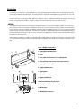
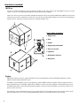
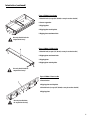
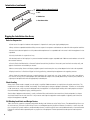
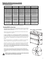
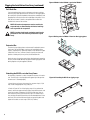
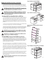
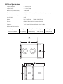
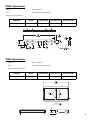
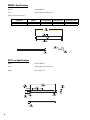
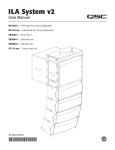
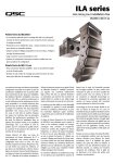
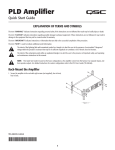
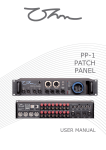
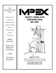
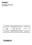
1675 MacArthur Blvd., Costa Mesa, CA, 92626 USA
Main Number (714) 754-6175 Sales & Marketing (714) 957-7100 or toll free (USA only) (800) 854-4079
Customer Service(714) 957-7150 or toll free (USA only) (800) 772-2834
ILA Series Loudspeaker System User Manual
WL2082-i full-range line array loudspeaker
WL115-sw subwoofer line array loudspeaker
FB2082-i array frame
EB2082-i extension bar
PB2082-i pull back bar
GS115-sw ground stack kit
*TD-000218-00*
TD-000218-00 revB
IMPORTANT SAFETY PRECAUTIONS
Install in accordance with QSC Audio Product's instructions and under the supervision of a licensed Professional Engineer.
WARNING!
Before placing, installing, rigging, or suspending any speaker product, inspect all hardware, suspension, cabinets, transducers, brackets and
associated equipment for damage. Any missing, corroded, deformed, or non-load rated component could significantly reduce the strength of
the installation, placement or array. Any such condition severely reduces the safety of the installation and should be immediately corrected.
Use only hardware which is rated for the loading conditions of the installation and any possible short-term, unexpected overloading. Never
exceed the rating of the hardware or equipment.
Consult a licensed, Professional Engineer regarding physical equipment installation. Ensure that all local, state and national regulations
regarding the safety and operation of suspended equipment are understood and adhered to.
Warranty (USA only; other countries, see your dealer or distributor)
Disclaimer
QSC Audio Products, Inc. is not liable for any damage to amplifiers or any other equipment that is caused by negligence or improper
installation and/or use of this loudspeaker product.
QSC Audio Products 3 Year Limited Warranty
QSC Audio Products, Inc. (“QSC”) guarantees its products to be free from defective material and / or workmanship for a period of three (3)
years from date of sale, and will replace defective parts and repair malfunctioning products under this warranty when the defect occurs
under normal installation and use - provided the unit is returned to our factory or one of our authorized service stations via prepaid transportation with a copy of proof of purchase (i.e., sales receipt). This warranty provides that the examination of the return product must
indicate, in our judgment, a manufacturing defect. This warranty does not extend to any product which has been subjected to misuse,
neglect, accident, improper installation, or where the date code has been removed or defaced. QSC shall not be liable for incidental and/
or consequential damages. This warranty gives you specific legal rights. This limited warranty is freely transferable during the term of the
warranty period.
Customer may have additional rights, which vary from state to state.
In the event that this product was manufactured for export and sale outside of the United States or its territories, then this limited warranty shall not apply. Removal of the serial number on this product, or purchase of this product from an unauthorized dealer, will void this
limited warranty.
Periodically, this warranty is updated. To obtain the most recent version of QSC’s warranty statement, please visit www.qscaudio.com.
Contact us at 800-854-4079 or visit our website at www.qscaudio.com.
© Copyright 2006, QSC Audio Products, Inc.
QSC® is a registered trademark of QSC Audio Products, Inc.
Speakon® is a registered trademark of Neutrik® and the names of Neutrik® products referenced herein are either trademarks and/or service marks of Neutrik®.
All trademarks are the property of their respective owners.
“QSC” and the QSC logo are registered with the U.S. Patent and Trademark Office
2
Introduction
The Installation Line Array (ILA) is a high performance line array system designed for the needs of Houses of Worship, Performing Arts
facilities and a multitude of other venue types. The current ILA family is composed of the WL2082-i line array element, WL115-sw subwoofer, FB2082-i array frame, PB2082-i pull-back bar, EB2082-i extension bar, and GS115-sw Ground Stack Kit.
Installation Line Arrays may be used in outdoor applications where the system is somewhat protected from the elements. The enclosure
material is formulated with UV inhibitors, the grille is made of aluminum and the woofer cones are weather resistant.
WL2082-i
The WL2082-i line array element uses two high-power, neodymium magnet, 2" voice-coil, 8" low-frequency drivers in a two-and-a-half
way configuration. Both woofers produce low-frequencies but only one covers the mid-range, resulting in far better horizontal directivity
control in the crossover region. Excellent high-frequency output and clarity are provided by a pair of 1.75" voice coil, neodymium magnet
compression drivers with titanium diaphragms. These drivers are mounted to a multiple-aperture diffraction waveguide that provides an
extremely wide horizontal coverage of 140º. As a result, systems will rarely require side or center fill speakers and solid stereo imaging is
preserved across the listening area.
The low-frequency capability of a WL2082-i array extends to 68 Hz (-10 dB); adequate for speech/vocal and acoustic music program material. For reinforcement of program material with more demanding low-frequency content, the WL115-sw companion subwoofer is available.
Figure 1: WL2082-i Loudspeaker
1- Rigging plate attachment holes
2- Grille
3- Splay angle selection holes (rear of rigging plates)
4- Grille retaining screws (one on each end of enclosure)
5- Rigging plate retaining bolt
6- Rigging alignment notch
7- Rigging plates
8- Input plate
9- Rigging alignment pin
10- Horizontal Shading selector switch
11- Bi amp/Tri amp Mode selector switch
12- Wiring table
13- NL8 Speakon connectors
3
Introduction (continued)
WL115-sw
The WL115-sw subwoofer extends the system’s low-frequency capability to 35 Hz. with a compact fourth-order bandpass enclosure. Its ceramic
magnet, 4” voice coil, 15” transducer provides 650 watt continuous power handling capability.
Many users of line array systems have found that suspending the subwoofers with the array provides audible benefit. Additionally, many venues
lack physical space for floor-mounted subs. For these reasons, the WL115-sw includes rigging hardware and, with selection of the appropriate
rigging accessories, subwoofers may be flown at the top of or behind a WL2082-i array.
Figure 2: WL115-sw Subwoofer
1- Rigging straps
2- Ports
3- Handles
4- Rigging strap retaining bolts
5- Driver access panel
6- Input panel
7- NL8 Speakon connectors
8- Wiring table
Rigging
Rigging the Installation Line Array is simple and flexible. Enclosures are bolted together with the provided M8 shoulder bolts or pinned
together with optional quick-release ball-lock pins.
The FB2082-i array frame supports most flown array applications, and the EB2082-i extension bar supports suspension where the center of
gravity is beyond the limits of the FB2082-i. Additionally, the EB2082-i is used for arrays where subwoofers are flown behind the main array.
The PB2082-i pull-back bar is used for pulling back the bottom element of the array for aiming and stability or as the primary suspension component for certain small arrays.
Ground stacking is easily accomplished using the GS115-sw Ground Stack Kit. The kit includes two ground stack rails which attach to the rigging straps under the WL115-sw. These rails provide added stability and allow for ground stacked arrays to be constructed.
4
Introduction (continued)
Figure 3: FB2082-i Array Frame
1- Shackle holes (accept 3/4” (20 mm) screw pin anchor shackle)
2- Center support bar
3- Rigging plates
4- Rigging plate retaining bolts
5-Rigging plate attachment holes
Use only shackle holes for
suspension of array!
Figure 4: PB2082-i Pull Back Bar
1- Shackle hole (accepts 5/8” (16 mm) screw pin anchor shackle)
2- Rigging plate attachment holes
3- Rigging plates
4- Rigging plate retaining bolts
Use only shackle hole for
suspension of array!
Figure 5: EB2082-i Extension Bar
1- Extension bar
2- Rigging plate retaining bolts
3- Shackle holes (accept 3/4” (20 mm) screw pin anchor shackle)
4- Rigging plates
Use only shackle holes
for suspension of array!
5
Introduction (continued)
Figure 6: GS115-sw Ground Stack Kit
1- Rail
2- Rubber foot
3- Attachment holes
Rigging the Installation Line Array
Rules for Suspension
•Correct use of all suspension hardware and components is imperative in sound system rigging and deployment.
•Always calculate suspended loads before lifting to ensure suspension components and hardware are used within their respective load limits.
•Research local codes and regulations to fully understand the requirements for suspended loads in the venue in which the equipment is to be
suspended.
•Use only shackle holes for suspension of array.
•Be absolutely certain of the integrity of any structural member intended to support suspended loads. Hidden structural members can have hidden structural weakness.
•Consult a Professional Mechanical or Structural Engineer licensed in the jurisdiction of the sound system installation to review, verify, and
approve all attachments to the building or structure.
•Never assume anything- Owner or third-party supplied suspension attachment points may not be adequate for the loads to be suspended.
•Employ the services of a Professional Rigger for hoisting, positioning, and attaching the equipment to the supporting structure.
•Always inspect all components (enclosures, suspension brackets, pins, frames, bolts, nuts, slings, shackles, etc.) for cracks, wear, deformation, corrosion, missing, loose, or damaged parts that could reduce the strength of the assembly before lifting. Discard any worn, defective, or
suspect parts and replace them with new appropriately load-rated parts.
Shock Loading
When a load is either moved or stopped, its static weight is magnified. Sudden movements can magnify the static weight several times. This
magnification of static weight is termed "shock loading". Shock loading poses a danger to equipment and workers. The effects of shock loading
can be instantaneous, or they may remain undetected unless the equipment is visually damaged. Avoiding shock loading requires careful planning and knowledge of equipment, rigging, and lifting practices.
Shock loading of equipment and structures is usually confined to lifting and installation, but natural forces (winds, earthquakes) can impose
shock loads several times the static load. This is why structures and suspension equipment must be capable of supporting several times the
weight of the equipment suspended.
ILA Working Load Limits and Design Factors
Table 1 lists the ILA suspension components and provides Working Load Limit data at various Design Factors. The tabulated Design Factors are
for static loads only. The choice of which Design Factor to use will depend upon the jurisdiction and venue of installation, as well as the conditions of suspension. Dynamic conditions are determined by unknown, installation-specific factors and should be referred to a Licensed Structural
Engineer for clarification before proceeding with any suspension of the equipment. The data presented is based upon the listed component
weights:
6
Rigging the Installation Line Array (continued)
Table 1: ILA Working Load Limits
Component
Weight
5:1 Design Factor
7:1 Design Factor
10:1 Design Factor
EB2082-i Extension Bar
38 lb (17.3 kg)
2400 lb(1090.0 kg)
1714 lb (779.2 kg)
1200 lb (545.5 kg)
FB2082-i Array Frame
17 lb (7.7 kg)
1036 lb (470.9 kg)
740 lb (336.4 kg)
518 lb (235.5 kg)
PB2082-i Pull Back Bar
6 lb (2.7 kg)
296 lb (134.5 kg)
211 lb (96.1 kg)
148 lb (67.3 kg)
WL2082-i Loudspeaker
37 lb (16.8 kg)
889 lb (403.2 kg)
634 lb (288.3 kg)
445 lb (201.8 kg)
WL115-sw Loudspeaker
111 lb (50.5 kg)
1036 lb (470.9 kg)
740 lb (336.4 kg)
518 lb (235.5 kg)
M8 Shoulder Bolt1
not applicable
1404 lb (638.2 kg)
1003 lb (455.8 kg)
702 lb (319.1 kg)
M8 Ball-lock Pin1
not applicable
2534 lb (1151.8 kg)
1810 lb (822.7 kg)
1267 lb (575.9 kg)
M12 Shoulder Bolt1
not applicable
6641 lb (3018.8 kg)
4744 lb (2156.3 kg)
3321 lb (1509.4 kg)
3/8” Fastener1
not applicable
2721 lb (1236.7 kg)
1943 lb (883.4 kg)
1360 lb (618.4 kg)
7/8” Fastener1
not applicable
11354 lb (5161.0 kg)
8110 lb (3686.4 kg)
5677 lb (2580.5 kg)
1- Working Load Limits are per fastener loaded in double shear. Data is for informational purposes only.
Attaching WL2082-i to Array Frame
Before beginning any installation, have your system designer configure the array with proper
splay angles using QSC’s EASE Focus (Array Calculator). All orientation of product is to be as
viewed from the rear of the enclosure.
Figure 7: WL2082-i attached to FB2082-i
Attach the array frame to the suspension structure using a 3/4” (20 mm) screw pin anchor
shackle and appropriate sling, cable, etc....
For arrays of 4 WL2082-i or less, assemble the cluster of WL2082-i on the ground using the
included mating hardware. Ensure the notched rigging plate is on the right hand side (the system can only be installed one way. Note the QSC logo on the input plate will be right side up
when the enclosure is oriented properly). During assembly, ensure your splay angles are as
desired.
When constructing large arrays it is recommended to first assemble units of four enclosures
and then assemble the final array by joining the four enclosure units to one another.
Attachment of one enclosure to another is accomplished by inserting the cap-head shoulder
bolt with washer through the rigging plate attachment holes and appropriate splay angle
selection holes in the mating rigging plates and threading the lock nut (nylock) on the inside
edge of the plates. The bolt should be tightened snuggly to no more than 5 lb-ft of torque (6.8
N-m). See Figure 7 for assembly detail.
Attach the array frame to the top enclosure by inserting the cap-head shoulder bolt with
washer through the appropriate mounting holes and threading the lock nut (nylock) on the
inside edge of the plates. The bolt should be tightened snuggly to no more than 5 lb-ft (6.8 N-m)
of torque.
NOTE: For some array configurations, use of the extension bar and/or pull-back
may be required to achieve the required aiming angle.
7
Figure 8:PB2082-i under WL2082-i attached to FB2082-i.
Rigging the Installation Line Array (continued)
Pull-Back Bar
If using the pull-back bar, attach to the bottom enclosure at the bottom-most splay angle adjustment holes at the rear of the rigging plate
by inserting the cap-head shoulder bolt through the mated pieces and
threading the lock nut (nylock) on the inside edge of the plates. Use a
5/8” (16 mm) shackle to attach to the pull-back bar shackle hole
located in the center of the main bar.
NOTE: All hardware/components must be rated for the
expected loads as determined by the Professional Engineer responsible for suspension.
NOTE: A washer should not be used when attaching the
pull back bar. This will allow the pull back bar to pivot
freely.
Figure 9: Bolting order for EB2082-i Extension Bar rigging plates.
Extension Bar
The extension bar rigging plates can be moved, if required, by removing the two 7/8”mounting bolts, moving to the selected mounting
location, and reattaching. Tightening torque is to be 100 lb-ft of torque
(135.6 N-m) Ease-Focus software’s center-of-gravity calculator will
provide a suitable point (or two points) for desired down-tilt.
Attach the array frame to the extension bar rigging plates by centering
the array frame member between the extension bar rigging plates and
bolting together using the supplied 7/8” bolts.
Attaching the WL115-sw to the Array Frame
All orientation of product is to be as viewed from the rear of the enclosure. The QSC logo on the input plate will appear right side up when
the enclosure is oriented properly.
1- Attach the array frame to the suspension structure using 3/4" (20
mm) shackle and appropriate sling, cable, etc....
2- Refer to Figure 10. For all four rigging straps: Using an 6mm hex
wrench, remove the upper and lower rigging strap retaining bolts and
loosen the two bolts in between. Pull the inner and outer straps to
their outermost position; pull the center strap to its outermost position, and align the retaining bolt holes with the threaded inserts of the
enclosure. Re-install the outermost rigging strap retaining bolts and
tighten all four bolts on each strap to 13 lb-ft (17.6 N-m).
8
Figure 10: Extending the WL115-sw rigging straps.
Figure 11: WL115-sw attached to FB2082-i.
Rigging the Installation Line Array (continued)
3- Lower the array frame onto the enclosure, carefully aligning the rigging straps, and
attach the top enclosure to the array frame by installing the ball-lock pins or M8 bolts.
Before lifting, ensure the audio connection to the enclosures are correct and functioning.
NOTE: When attaching one WL115-sw to another WL115-sw, you must use
the supplied ball-lock pins. This will allow for easier installation given the
close spacing between consecutive WL115-sw enclosures.
NOTE: When arraying two or more WL115-sw subwoofers, it is easiest to
lay the enclosures on their backs, align and mate the rigging straps, and
install the ball-lock pins. When installing the ball-lock pins, ensure full
insertion and locking action.
Figure 12: WL115-sw to WL115-sw rigging.
Attaching the GS115-sw Ground Stack Rails to a WL115-sw
1- For all four rigging straps: Using an 6mm hex wrench, remove the upper and lower rigging strap retaining bolts and loosen the two bolts in between. Pull the inner and outer
straps to their outermost position; pull the center strap to its outermost position, and
align the retaining bolt holes with the threaded inserts of the enclosure. Re-install the
outermost rigging strap retaining bolts and tighten all four bolts on each strap to 13 lb-ft
(17.6 N-m).
2- Position a GS115-sw Ground Stack rail between the rigging straps on the right and one
to the outside of the rigging straps on the left side of the loudspeaker.
3- Attach the rail to the rigging strap by inserting the cap-head shoulder bolt with washer
through the mated components and threading the lock nut (nylock) on the inside edge of
the assembly. The bolt should be tightened snuggly to no more than 5 lb-ft (6.8 N-m).
Figure 13: GS115-sw Ground Stack Rails attached to
WL115-sw.
NOTE: GS115-sw must be attached to at least one WL115-sw for stability
before any additional loudspeakers are attached. GS115-sw should never
be attached to a WL2082-i loudspeaker.
NOTE: GS115-sw is designed to accommodate up to two WL115-sw loudspeakers and up to six WL2082-i loudspeakers.
Attaching WL2082-i enclosures beneath WL115-sw enclosures
For arrays of 4 WL2082-i loudspeakers or less, assemble the WL2082-i loudspeakers on
the ground using the included mating hardware. Ensure the notched rigging plate is on the
right hand side (the system can only be installed one way; the QSC logo on the input plate
will appear right side up when the enclosure is oriented properly). During assembly,
ensure your splay angles are as desired.
When constructing large arrays it is recommended to first assemble units of four enclosures and then assemble the final array by joining the four enclosure units to one another.
Attachment of one enclosure to another is accomplished by inserting the cap-head shoulder bolt with washer through the mated rigging plates and appropriate splay angle selection holes and threading the lock nut (nylock) on the inside edge of the plates. The bolt
should be tightened snuggly to no more than 5 lb-ft (6.8 N-m). See Figure 7 for assembly
detail.
Figure 14: WL2082-i attached to WL115-sw and FB2082-i.
Lower the array frame with subwoofer(s) onto the WL2082-i enclosure cluster and attach
the top enclosure to subwoofer by inserting the cap-head shoulder bolt with washer
through the mounting holes and threading the lock nut (nylock) on the inside edge of the
plates and rigging straps.
NOTE: See Pull-Back Bar and Extension Bar sections on previous page for
information regarding their use.
9
Rigging the Installation Line Array (continued)
Attaching WL115-sw behind WL2082-i array using EB2082-i
Figure 15: EB2082-i with WL115-sw suspended at
rear and WL2082-i array suspended at front.
It is sometimes necessary to suspend the subwoofers behind the main array. Extreme
splay angles may result in physical interference with rear-flown subwoofers.
Attach both array frames to the extension bar rigging plates by centering the array frame
member between the extension bar rigging plates and bolting together using the supplied 7/8” bolts. The extension bar rigging plates can be moved, if required, by removing
the two 7/8”mounting bolts, moving to the selected mounting location, and reattaching.
Tightening torque is to be 100 lb-ft (135.6 N-m). Ease-Focus software’s center-of-gravity
calculator will provide a suitable point (or two points) for desired down-tilt.
The rear suspended WL115-sw subwoofer(s) may now be attached to the array frame;
see “Attaching the WL115-sw to the Array Frame”
The front suspended WL2082-i loudspeakers may now be attached to the array frame;
see “Attaching WL2082-i to Array Frame”
NOTE: When stacking loudspeakers for attachment to array frames using
the extension bar, we recommend working with groups of 2 WL2082-i for
each WL115-sw. Start with no splay angle; this yields the same height for landing the extension
bar. Adjust splay angle once the rig is lifted.
Suspending 4 or less WL2082-i Loudspeakers Using Two Pull-Back Bars
NOTE: Do not suspend more than 4 WL2082-i loudspeakers from a PB2082-i pull-back bar! Do not
use PB2082-i pull-back bar for suspending anything other than 4 or less
WL2082-i loudspeakers! Do not suspend the WL115-sw from the PB2082-i
pull-back bar!
Figure 16: Using two PB2082-i Pull Back Bars for
NOTE: A washer should not be used when attaching the pull back bar. This suspending a maximum of 4 WL2082-i loudspeakers.
will allow the pull back bar to pivot freely.
Assemble the array of WL2082-i loudspeakers on the ground using the included mating
hardware. Ensure the notched rigging plate is on the right hand side (the system can only
be installed one way. Note the QSC logo on the input plate will appear right side up when
the enclosure is oriented properly.
Attachment of one enclosure to another is accomplished by inserting the cap-head shoulder bolt with washer through the mated rigging plates and appropriate splay angle selection holes and threading the lock nut (nylock) on the inside edge of the plates. The bolt
should be tightened snuggly to no more than 5 lb-ft of torque (6.8 N-m). See Figure 7 for
assembly detail.
Attach one PB2082-i to the top enclosure’s front, top rigging plate attachment holes by
inserting the cap-head shoulder bolts without washers through the mated pieces and
threading the lock nut (nylock) on the inside edge of the plates. The bolts should be tightened snuggly to no more than 5 lb-ft of torque. See Figure 7 for assembly detail. Use a 5/
8” (16 mm) screw pin anchor shackle to attach to the pull-back bar shackle hole located in
the center of the pull back bar for lifting.
Attach the second PB2082-i to the bottom enclosure at the bottom-most splay angle
adjustment holes at the rear of the rigging plate by inserting the cap-head shoulder bolts
without washers through the mated pieces and threading the lock nut (nylock) on the
inside edge of the plates. The bolts should be tightened snuggly to no more than 5 lb-ft
(6.8 N-m) of torque. See Figure 7 for assembly detail. Use a 5/8” (16 mm) screw pin anchor
shackle to attach to the pull-back bar shackle hole located in the center of the main bar for
pulling back.
10
Warning! Four (4) WL2082-i loudspeakers
is the maximum allowable load (10:1
design factor) for the PB2082-i. Do not suspend more than four WL2082-i loudspeakers from
the PB2082-i.
WL2082-i Controls and Connections
Figure 17: MODE selection switch.
MODE Selection Switch
BI AMP: When set to BI AMP, an internal shading network removes the mid-frequencies from one of the lowfrequency drivers. The BI AMP HORIZONTAL SHADING
switch will select which transducer is shaded.
TRI AMP: Shading network is NOT applied (shading
must be provided by upstream signal processing). The
Bi Amp Mode Horizontal Shading selector switch is not
functional in tri amp mode. Connect to the Speakon as
shown for tri amp.
Figure 18: BI AMP MODE HORIZONTAL SHADING selection switch.
BI AMP MODE HORIZONTAL SHADING
Selection Switch
The BI AMP MODE HORIZONTAL SHADING selection
switch is only functional in bi amp mode. This switch
determines which low-frequency transducer receives
only low-frequency program material (shading). The unshaded transducer receives low- and mid-frequency
program material. This allows switch position selection
for use as either “house left” or “house right”, without
the need to flip boxes.
NOTE: LEFT and RIGHT markings on the BI
AMP HORIZONTAL SHADING SWITCH apply
to the enclosure as viewed from the rear (i.e.
looking at the Input Plate with the text properly oriented).
LF2
LF1
Table 2: WL2082-i Connector Pinout for BI AMP and TRI AMP Mode
PIN
BI AMP
TRI AMP
1+
Through
Through
LEFT: Use this setting to steer coverage to the left (as
viewed from behind the arrays, looking toward the
audience).
1-
Through
Through
2+
No Connection
Left Low Frequency
Transducer + (16 Ohms)
RIGHT: Use this setting to steer coverage to the right
(as viewed from behind the arrays, looking toward the
audience).
2-
No Connection
Left Low Frequency
Transducer - (16 Ohms)
3+
Left and Right Low Frequency Transducers in
Parallel + (8 Ohms)
Right Low Frequency
Transducer + (16 Ohms)
3-
Left and Right Low Frequency Transducers in
Parallel - (8 Ohms)
Right Low Frequency
Transducer - (16 Ohms)
4+
High Frequency Transducer + (16 Ohms)
High Frequency Transducer + (16 Ohms)
4-
High Frequency Transducer - (16 Ohms)
High Frequency Transducer - (16 Ohms)
Input Connections
The WL2082-i input connectors are a pair of Neutrik
NL8's wired in parallel. Connections for biamp and triamp vary, see Table 2 or the pinout table on the
WL2082-i input plate (Figure 19).
The WL2082-i loudspeaker is not equipped
with a crossover network. All signal processing must be done before connecting
audio power to the loudspeaker. Do not connect full-range audio to the high-frequency
transducer or damage may result!
Figure 19: Pinout table as printed on WL2082-i input plate label
11
WL115-sw Connections
Figure 20: WL115-sw Input Plate
Input Connections
The WL115-sw input connectors are a pair of Neutrik
NL8's wired in parallel. See Table 3 or the WL115-sw
Input Plate for connector pinout.
Note pin numbers 2+, 2-, 3+, 3-, 4+, and 4- are
wired straight through from one connector to
the other. This accommodates using one input
cable assembly (where appropriate) for subwoofer and full range loudspeaker connections. Additionally, pin numbers 1+ and 1- of
both NL8s are wired in parallel.
Table 3: WL115-sw Connector Pinout
PIN
Connection
1+
Low Frequency Transducer + (8 Ohms)
1-
Low Frequency Transducer - (8 Ohms)
2+
Through
2-
Through
3+
Through
3-
Through
4+
Through
4-
Through
Figure 21: Pinout table as printed on WL115-SW Input Plate
Neutrik NL8FC Cable Connector Pinout
Figure 22 shows the pin designations inside the Neutrik
NL8FC connector. This information is for reference only.
Diagram is of the connector as viewed from the wireinsertion end.
12
Figure22: NL8FC pin designations- Plug viewed from the wiring side.
WL2082-i Specifications
Frequency Response:
80 - 20,000 Hz (+/- 3 dB)
Frequency Range:
68 - 22,000 Hz (-10 dB)
Maximum SPL (continuous/peak):
HF: 126/132 dB
Nominal Coverage (-6 dB included):
Horizontal: 140 degrees (500 Hz to 3.2 kHz)Vertical: dependant on cumulative splay angle
LF: 122/128 dB
Transducers:
High Frequency:
Dual 50W, 8 Ohm 1 inch exit, 1.75 inch titanium diaphragm, neodymium magnet assembly
Low Frequency:
Dual 200W, 16 Ohm 8 inch cone transducer, 2 inch voice coil, neodymium magnet assembly,
weather resistant cone
Acoustic Crossover Frequency:
High to Mid: 2000 Hz
Input Sensitivity:
HF: 106 dB
Mid to Low: 230 Hz
LF: 96 dB
Weight:
Net: 37 lb (16.8 kg)
Shipping: 45 lb (20.5 kg)
Enclosure:
High-impact Polystyrene with ultraviolet (UV) protectant, paint finish.
Grille:
Perforated aluminum
Connectors:
Two (2) Neutrik NL8 in parallel (wired as shown in Table 2)
Working Load Limit Information:
Component
Weight
5:1 Design Factor
7:1 Design Factor
10:1 Design Factor
WL2082-i Loudspeaker
37 lb (16.8 kg)
889 lb (403.2 kg)
634 lb (288.3 kg)
445 lb (201.8 kg)
13
WL115-sw Specifications
Frequency Response:
37 - 107 Hz (+/- 3 dB)
Frequency Range:
35 - 112 Hz (-10 dB)
Maximum SPL (continuous/peak):
124 dB/130 dB
Transducer:
650W, 8 Ohm 15 inch woofer, 4 inch voice coil, ceramic magnet assembly
Recommended Crossover Frequency:
35 - 85 Hz
Input Sensitivity:
96 dB
Weight:
Net: 111 lb (50.4 kg)
Enclosure:
0.708 inch (18 mm) Baltic birch plywood, paint finish.
Connectors:
Two (2) Neutrik NL8 in parallel (wired as shown in Table 3)
Shipping: 121 lb (55.0 kg)
Working Load Limit Information:
14
Component
Weight
5:1 Design Factor
7:1 Design Factor
10:1 Design Factor
WL115-sw Loudspeaker
111 lb (50.5 kg)
1036 lb (470.9 kg)
740 lb (336.4 kg)
518 lb (235.5 kg)
EB2082-i Specifications
Material:
Aluminum 6061-T6
Finish:
Black powder coat (White optional)
Working Load Limit Information:
Component
Weight
5:1 Design Factor
7:1 Design Factor
10:1 Design Factor
EB2082-i Extension Bar
38 lb (17.3 kg)
2400 lb (1090.0 kg)
1714 lb (779.2 kg)
1200 lb (545.5 kg)
FB2082-i Specifications
Material:
Aluminum 6061-T6
Finish:
Black powder coat (White optional)
Working Load Limit Information:
Component
Weight
5:1 Design Factor
7:1 Design Factor
10:1 Design Factor
FB2082-i Array Frame
17 lb (7.7 kg)
1036 lb (470.9 kg)
740 lb (336.4 kg)
518 lb (235.5 kg)
15
PB2082-i Specifications
Material
Aluminum 6061-T6
Finish
Black powder coat (White optional)
Working Load Limit Information:
Component
Weight
5:1 Design Factor
7:1 Design Factor
10:1 Design Factor
PB2082-i Pull Back Bar
6 lb (2.7 kg)
296 lb (134.5 kg)
211 lb (96.1 kg)
148 lb (67.3 kg)
GS115-sw Specifications
16
Material
Aluminum 6061-T6
Finish
Black powder coat (White optional)
Weight
5 lb (2.3 kg) per set
17
18
19
How to Contact QSC Audio Products
Mailing address:
QSC Audio Products, Inc.
1675 MacArthur Boulevard
Costa Mesa, CA 92626-1468 USA
Telephone Numbers:
Main Number
(714) 754-6175
Sales & Marketing
(714) 957-7100 or toll free (USA only) (800) 854-4079
Customer Service
(714) 957-7150 or toll free (USA only) (800) 772-2834
Facsimile Numbers:
Sales & Marketing FAX
(714) 754-6174
Customer Service FAX
(714) 754-6173
World Wide Web:
www.qscaudio.com
E-mail:
[email protected]
[email protected]
QSC Audio Products, Inc. 1675 MacArthur Boulevard Costa Mesa, California 92626 USA
©2006 “QSC” and the QSC logo are registered with the U.S. Patent and Trademark Office.