1
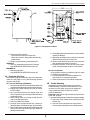
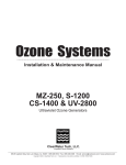
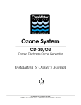
TM
CORONA DISCHARGE
OZONE GENERATORS
CD-7 THRU CD-15
Main Power
Ozone Power
Vacuum
High Coolant Temperature
High Transformer Temperature
Water Backflow Detector
INSTALLATION & OPERATIONS MANUAL
DEL INDUSTRIES, INC. · SAN LUIS OBISPO, CA 93401 · USA · 800-676-1335 · Fax: 805-541-8459
012400 / 4-0401
CD-7 thru CD-15 Infinity Corona Discharge Ozone Generator
TABLE OF CONTENTS
SECTION 1
SECTION 4
General Information
Maintenance & Service
1A. Description ........................................................... 1
1B. Specifications ...................................................... 1
1C. Warranty Summary............................................... 1
4A. System Electro-Mechanical Overview ................. 4
4B. PM Schedule ....................................................... 4
4C. Generator Servicing ............................................. 5
4D. Trouble Shooting .................................................. 5
SECTION 2
SECTION 5
Installation
2A. Location ............................................................... 1
2B. Mounting .............................................................. 1
2C. Electrical ............................................................. 2
2D. Plumbing ............................................................. 2
2E. ORP Sensor Connection ...................................... 2
Replacement Parts & Order Info
5A. Ordering Information ............................................ 6
5B. Standard Replacement Parts List ......................... 6
Warranty ...................................................... 7
Appendix
SECTION 3
Appendix A (Safety) ................................................... 8
Operation
3A. General ................................................................ 3
3B. Initial System Start-Up ........................................ 3
3C. Normal Operation ................................................. 3
3D. Shut-Down ........................................................... 3
3E. Water Chemistry .................................................. 3
ALL Infinity CD Ozone Generators are
UL Classified and NSF Listed.
IMPORTANT SAFETY INSTRUCTIONS
READ AND FOLLOW ALL INSTRUCTIONS.
· Read this manual completely before attempting installation.
· Install at least 5 feet (1.5meters) from wall of spa or pool water using nonmetallic plumbing. Install ozone generator
no less than one (1) foot above maximum water level to prevent water from contacting electrical equipment. Install
in accordance with the installation instructions.
· Connect to a grounded, grounding type receptacle only.
· Do not bury cord.
· Warning - To reduce the risk of electrical shock, replace damaged cord immediately.
· Follow all applicable electrical codes.
· Electric shock hazard. Be sure to turn power OFF and disconnect from power source before any service work is
performed. Failure to do so could result in serious injury or death.
· Warning - Short term inhalation of high concentrations of ozone and long term inhalation of low concentrations of
ozone can cause serious harmful physiological effects. DO NOT inhale ozone gas produced by this device.
· For your safety, do not store or use gasoline, chemicals or other flammable liquids or vapors near this or any other
appliance.
· A spontaneous and violent ignition may occur if oil, grease or greasy substances come in contact with oxygen
under pressure. These substances must be kept away from oxygen regulators, cylinder valves tubing and connections, and all other oxygen equipment.
SAVE THESE INSTRUCTIONS!
CD-7 thru CD-15 Infinity Corona Discharge Ozone Generator
1C. Warranty Summary
SECTION 1
Limited Warranty:
2 years on entire generator
In addition to the two (2) year warranty:
3 years on weldments
5 years on high voltage electrodes
2 years on compressors that are maintained
according to operation and maintenance manual.
General Information
1A. Description
The Infinity™ Corona Discharge series ozone generator
described in this manual is designed to provide the benefits of ozonated water in an environmentally safe and
effective manner. Infinity™generators are UL and NSF
listed. The high quality, specially engineered components
ensure efficient ozone output and reliable performance.
SECTION 2
As a result of proper use of the Infinity™CD ozone generators, unpleasant effects of traditional chemical use,
(dry skin, red eyes, green hair) are virtually eliminated.
The Infinity CD ozone generator is safe and harmless to
your equipment if installed properly.
Installation
2A. Location
CD-7 and CD-15 are designed for either floor or wall mounting in a clean, protected area, either indoors or outdoors.
Locate generator out of reach of sprinklers or drainage
spouts. Allow sufficient access for maintenance and all
tubing and electrical wires. Ozone generator should be
installed no less than one foot above maximum water
level.
1B. Specifications
Ozone Output:
Ozone output (+10%): CD-7 .......... 7 g/hr
CD-15 ........ 15 g/hr
Flow rate (max):
CD-7 .......... 7 scfh (3.5 lpm)
CD-15 ........ 15 scfh (7 lpm)
% weight O3:
2.5-3.0%
Power Requirements:
Domestic: CD-7 ..... 115VAC, 50/60 Hz, 1Ø, 6.0 Amp
CD-15 .... 115VAC, 50/60 Hz, 1Ø, 7.5 Amp
Export*: CD-7 ..... 230VAC, 50 Hz, 1Ø, 3.5 Amp
CD-15 .... 230VAC, 50 Hz, 1Ø, 4.0 Amp
Cooling Water Requirements:
.1 GPM (.4 lpm) of clean, filtered, fresh water.
NOTE: Typical pool water may be used for cooling.
Generator efficiency and life will be improved at inlet
temperatures of 80°F or less.
Inlet temperature: 50°F - 90°F (10°C - 32°C)
Inlet pressure:
15.0 - 40 psi (100 - 270 kPa)
Shipping Weight:
CD-7: Approx. 135 pounds / 61 kilos
CD-15: Approx. 150 pounds / 70 kilos
Location Requirements**:
Mounting:
Floor or wall mount in a clean, protected
area using supplied brackets.
Ambient Temp: 40°F - 100°F (5°C - 40°C)
Ventilation:
6 air changes per hour. (min)
Figure 1: Wall Mount
* 230V/50Hz unit supplied with enclosed step down transformer
**Protection from weather elements must be provided for
outdoor installations. Operating outside of the recommended temp. ranges may result in damage not covered
under the manufacturer’s warranty.
1
CD-7 thru CD-15 Infinity Corona Discharge Ozone Generator
2B. Mounting
2B-1. Wall Mount Option
1. Attach two mounting brackets to wall using anchors
appropriate for mounting surface. See figure 1.
2. Using 1/4"-20 bolts (with washers as shown) secure generator to mounts.
2B-2. Floor Mount Option
1. Use the 4 1/4"-20 bolts with washers to secure feet
to bottom of cabinet.
2. Stand upright and securely fasten to concrete slab
using appropriate anchors and bolts.
2C. Electrical
Main power circuit: Unit is supplied with a standard
power cord. Plug cord into standard 110V grounded,
grounding type receptacle only. NOTE: The circuit must
be protected by a ground-fault circuit interrupter (GFCI)
installed in accordance with electrical codes.
2D. Plumbing
Ozone gas is introduced to the pool circulation line using
a venturi injector. Suction developed by the venturi allows
the CD to operate safely under vacuum. See installation
manual for MX-600-CD for proper venturi installation.
2D-1. Ozone Gas Line
1. Connect ozone tubing to generator outlet fitting.
(3/8" stainless steel compression fitting.)
2. Connect opposite end of ozone tubing to injector
suction port. (Suction port fitting: 3/8" stainless
steel compression fitting.) See figure 2.
Figure 2: Plumbing Schematic
2E. ORP Sensor Connection
(For optional ORP Controller) Consists of mounting the
ORP probe and routing the sensor cables.
NOTE:The ozone gas supply line must have a back flow
prevention device (such as a check valve) installed between the ozone generator cabinet and the point of
injection to prevent water from backing up into the
generator system. An ozone supply check valve is
included with the MX-600-CD system.
2E-1. ORP Probe Mounting
The sensor should be placed in the water stream at a
point downstream from the ozone injector. See figure 2.
1. Locate the point of insertion in the process pipe.
NOTE: Install the ORP probe in a location which
provides easy access for removal and cleaning of
the probe. The probe should be installed such that
the main stream ORP is measured. Locating the
ORP probe upstream of the ozone measures the
"pool" water. Locating the probe downstream of the
ozone measures the ORP of water returning to pool.
2. Install an appropriately sized tee in the process
line or drill and tap a 1/2" FPT hole in the process
pipe as shown in figure 3.
3. Remove the protective cap and apply Teflon tape
to the sensor threads. Thread the sensor into the
fitting or tapped hole. Save the protective sensor
cap for storage.
4. Start the circulation system and check for leaks
around the sensor.
2D-2. Cooling Water
Cooling water must be supplied as specified in section 1B.
1/4" FPT connections are supplied on the generator.
See figure 2. Be sure that the tubing is appropriately
matched with the marked inlet and outlet ports. Carefully match and connect to water plumbing as shown
in figure 2. Alternate method using connections at injector may be used.
2
CD-7 thru CD-15 Infinity Corona Discharge Ozone Generator
Both (2) green indicator lights should be lit. If the optional
ORP Controller is installed, it should be displaying a reading from the sensor probe and will automatically cycle the
generator on and off as needed to maintain water quality.
A high ORP (650-750 mV) is necessary for biological control.
However, the system will not start under any of the following conditions:
1. If the optional ORP controller is installed the system
will not start up if the ORP level is already above
the setpoint of the ORP controller.
2. The system will not start up if the door is not secured. A door interlock switch is incorporated into
the system enclosure.
3. The system will not start up if there is not enough
vacuum being generated by water flow through
injector. Red vacuum light will go out when proper
vacuum is attained.
4. System will not operate if there is too much
vacuum. Red vacuum light will go out when
proper vacuum is attained.
Figure 3: ORP Probe
2E-2. ORP Cable Routing:
Route the cable away from other power wires and protect
cable from damage. (i.e. Conduit or attached to plumbing.) Connect the sensor cable to the BNC connector located on the left exterior wall of the generator cabinet.
SECTION 3
Operation
If you experience complications, see TROUBLESHOOTING section 4C or call 800-676-1335 for assistance.
3A. General
To achieve optimal performance from the ozone system,
the pool must be as clean as possible to start with.
1. Backwash or clean filters one day before starting
the ozone generator.
2. Superchlorinate pool water using a chlorine based
shock treatment.
3. Test pool chemistry and adjust pH between 7.4 and
7.6. Adjust total alkalinity between 80 and 120 ppm.
4. Run pool filtration continuously for 24 hours prior to
starting ozone system.
3D. System Shut-Down
The Infinity Corona Discharge ozone generator is a specialized water cooled device that must be properly protected
during shut-down/storage periods.The following sequence
of steps must be used for servicing or for storage.
1. Toggle the main system power switch to the “OFF”
position to shut down generator.
2. After the generator has been shut down, the process water circulation pump may be turned off.
3. If the system is going to be shutdown and stored
during freezing weather, it is very important that
the cooling water jacket be drained to protect it from
rupture or damage.
3B. Initial System Start-Up
Upon completing all of the generator system connections
and cleaning the pool as outlined above, you are ready to
begin start up procedures.
1. Check electrical fittings.
2. Check for proper voltage.
3. Turn on circulation pump.
4. Check for leaks.
5. Check cooling water.
6. Adjust injector by-pass to attain required vacuum.
(Red vacuum light will go out)
7. Turn main power switch to "ON" position.
NOTE: Process water flow must not be shut down when
the ozone generator is operating. Doing so may cause
water to backflow into the system and damage the generator module and electrodes.
3E. Water Chemistry
Regular chlorine/bromine testing should be performed as
normal. Ozone will be eliminating the majority of contaminants. Therefore, only a small amount of chemicals will
need to be added - just enough to maintain a minimum of
residual level of .5-1.0 ppm chlorine or 1.0-2.0 ppm bromine. Ozone has very little if any impact on pH, reducing
pH adjustments to a minimum.
3C. Normal Operation
At this point, the system’s cooling fans will start up. The
oxygen concentrator will begin operating and the output
solenoid valve will open. The ozone generator should be
producing ozone and injecting it into the process line.
3
CD-7 thru CD-15 Infinity Corona Discharge Ozone Generator
SECTION 4
4A-3. Internal Components
1. Corona Discharge (CD) Module: Generator
module consists of stainless steel water jacket
and ground tubes and two end housings.
Enclosed inside the module are the high voltage
glass tube electrodes. The top end housing (the
cylindrical glass chamber) encloses the high
voltage connection for the electrodes and allows
for visual inspection.
2. High Voltage Transformer(s): Transformer raises
supplied voltage up to the voltage necessary for
ozone production. Transformer is thermally
protected by a temperature switch attached to the
transformer casing.
3. Air Compressor: Compressor produces and
supplies compressed air to oxygen concentrator.
4. Oxygen Concentrator: Supplies concentrated,
dry, oxygen feed gas to the ozone generator.
5. Lo Limit Vacuum Switch: If the vacuum in the
ozone output supply line falls below 2 in. Hg the
switch will open causing the system to shut down.
6. Hi Limit Vacuum Switch: If the vacuum in the
ozone output supply line rises above 10 in. Hg the
switch will open causing the system to shut down.
7. Water Backflow Detector: Backflow detector
senses water present in ozone tubing in generator.
If water is detected, system will close solenoid
valve to prevent additional water backflow from
occuring. Water in the generator will cause severe
damage to the high voltage electrodes.
8. Ventilation Fan: Cooling fan operates when main
power switch is “ON”.
9. Air Filter: Filter cleans ventilation air entering the
enclosure.
10. Door Interlock Switch: Interlock switch will shut
down entire system if door is opened. Securing
the door will bring the system back into operation.
11. Relay Panel: Contains control relays for system
interlocks, indicator lights and main power control.
Maintenance and Service
4A. System Electro-Mechanical Overview
Refer to Figure 4 for component locations.
4A-1. Indicator Lights
1. Main Power: Green light indicates that power is
being supplied to the ozone generator.
2. Ozone Power: Green light indicates that power is
being supplied to the high voltage Corona Discharge
circuits and that ozone is being produced.
3. Vacuum: Red light indicates proper vacuum being
supplied from the venturi injector. Light will be lit for
either low or high vacuum conditions.
4. High Coolant Temperature: Red light indicates
coolant temperature is over 150°F - resulting from
loss of cooling water flow. (Refer to TROUBLESHOOTING section.)
5. High Transformer Temperature: Red light indicates
transformer temperature is over 150°F - resulting
from high current through the transformer. (Refer to
TROUBLESHOOTING section.)
6. Water Backflow Detected: Red light indicates water backflow from injector into generator. (Refer to
TROUBLESHOOTING section.)
4A-2. Remaining External Components
1. Main Power Switch: Power switch is used for system start-up and shut-down. Switch activates the
control system allowing the generator to start up.
2. Flowmeter: Flowmeter controls and indicates the
oxygen flow through the system.
3. Circuit Breaker: Circuit breaker protects the generator from over current conditions. Push the breaker
button to reset.
4. ORP Controller (optional): ORP controller receives
a millivolt (mV) signal from the ORP sensor mounted
in the process water line. ORP (Oxidation-Reduction Potential) is a measure of the relative oxidation strength of the water. As ozone is added to the
water system the ORP level will rise. As ozone is
used up in the water system the ORP level will
drop. The ORP controller continuously analyses the
sensor signal, compares it to the setpoint that has
been programmed, indicates the ORP level on the
digital display, and relays the signal to the ozone
generator.
5. Variac (Optional): Variac adjusts high voltage
power supplied to the ozone generator module
controlling ozone output concentration.
4B. Preventative Maintenance Schedule
The Infinity™ Corona Discharge ozone system requires very
little maintenance beyond general housekeeping practices.
DAILY:
1. Check ozone generator for proper operation.
- Make sure no red indicator lights are lit.
- Make sure flow meter is indicating proper air flow.
2. Practice normal pool maintenance.
MONTHLY:
1. Remove and clean ORP probe.
- Remove from water stream.
- Clean tip of probe with non-abrasive cleanser to
remove any contaminant build up on probe.
- If there is a heavy build up on probe surface,
clean with a mild muriatic solution.
- Rinse and return to water stream.
4
CD-7 thru CD-15 Infinity Corona Discharge Ozone Generator
Figure 4: Component Locations
8. Gently glide glass tube electrodes out from module.
Inspect for damage.
9. Wipe down electrodes using a solvent such as denatured alcohol and set in a safe area.
10. Swab out the stainless steel tubes using a solvent
such as denatured alcohol or acetone.
11. Replace electrodes - be sure to wipe off any fingerprints, and reassemble module in reverse order.
2. Remove and clean air filter.
- Remove filter housing to access filter.
- Rinse filter in warm, soapy water and blow dry.
- Replace filter.
3. Perform general cleaning of cabinet interior.
ANNUALLY:
1. Remove, disassemble and clean CD module.
See GENERATOR SERVICING section 4C.
BIANNUALLY:
1. Rebuild compressor.
See GENERATOR SERVICING section 4C.
4C-2. Air Compressor
Air compressor requires a rebuild every two (2) years
or 15,000 hours of operation.
1. Purchase rebuild kit from DEL Industries, Inc.
See Section 5 for ordering information.
2. Follow instructions in kit to rebuild compressor.
4C. Generator Servicing
Before performing any servicing to the ozone generator,
make sure the power is off by disconnecting electrical
plug from wall socket.
4C-1. Corona Discharge (CD) Module
1. Disconnect the wires from the thermostat switch and
ground terminal attached to the generator housing.
2. Unplug high voltage cable(s) from the top end of
the CD module.
3. Very carefully disconnect the oxygen feed and
ozone output lines by removing the stainless steel
compression nuts.
4. Drain cooling water from ozone module and disconnect cooling water lines.
5. Remove module from cabinet.
6. Carefully remove glass end housing, inspect for
damaged glass or retainer springs, and set aside.
7. Remove the opposite end (aluminum discharge end)
taking care not to lose retainer springs. Inspect for
damage and set aside.
4D. Trouble Shooting
Knowledge of electrical applications is required for
trouble shooting. Contact a certified electrician if you
are unsure of your ability to service the equipment.
If any condition persists, call 800-676-1335 for
technical assistance.
Symptom: “Main power” light out when system switch is
in the "ON" position.
1. No power to the generator module from the power supply:
a. Check the circuit breaker at the facility power distribution box.
b. Check for loose connections or wiring breaks
from the power distribution box to the generator.
5
CD-7 thru CD-15 Infinity Corona Discharge Ozone Generator
2. G.F.C.I. has tripped.*
a. Check power cord and reset G.F.C.I.
3. Circuit breaker has tripped.*
a. Reset breaker.
*If G.F.C.I. or breaker continue to trip after reset, call
for technical assistance.
2. Excessive ambient temperatures in installation area.
a. Generator should not be exposed to ambient
temperatures above 100°F. Higher temperatures
may damage generator components.
Symptom: “Water backflow detected” indicator light is on.
1. Water has backed into generator from injector.
a. Establish proper water flow through injector and
correct suction.
b. Drain Back Flow Preventer by first routing drain
tubing out of cabinet.opening cabinet and opening
1/4" stainless steel ball valve.
c. After water has completly drained close drain
valve, secure cabinet door and restart system.
Symptom: “Ozone power” indicator light out.
1. If optional ORP is installed, ORP may have shut down
the generator when ORP level reached setpoint.
a. Wait for ORP to come down. Generator will
restart when ORP level is below set point.
2. Abnormal operating condition exists.
a. Check red fault indicator lights. Refer to corresponding symptom and corrective action.
Symptom: CD Module is not operating. Ozone output
has dropped.
1. No power to the generator module from the power supply:
a. Check H.V. cables for breaks or loose connections,
replace if necessary.
b. Check for power at input terminals of the H.V.
transformers.*
c. Check ozone power relay for loose connections
or faulty operation.
*CAUTION: HIGH VOLTAGE.
Symptom: “Vacuum” indicator light is on indicating out of
range vacuum being supplied.
1. Injector not supplying adequate suction.
a. Check pump and ensure water is flowing through
injector.
b. Check by-pass valve and adjust if necessary to
obtain proper pressure differential in order to
reestablish suction.
2. Injector supplying too much suction.
a. Check by-pass valve and adjust to obtain proper
suction.
b. Check system back pressure and increase to
reduce suction.
3. Another abnormal condition exists causing ozone output solenoid valve to be closed.
a. Check red fault indicator lights. Refer to corresponding symptom and corrective action.
b. Solenoid valve may be stuck in closed position.
Free solenoid plunger and return system to
normal operation.
Symptom: No air flow through the generator. The air flow
meter indicates 0 scfh flow.
1. Flowmeter control valve is improperly set:
a. Open flowmeter valve until proper air flow is
indicated (~8 scfh for CD-7, ~14 scfh for CD-15).
2. Air compressor is not operating properly.
a. Listen for air compressor operation.
b. Check all tubing connections from the air compressor through the system for leaks.
SECTION 5
Symptom: “High coolant temperature” indicator light is
on indicating ozone module temperature over 150°F.
1. Coolant water flow has been interupted.
a. Check all tubing connections, ensureing tight,
leak free connections.
b. Trace tubing and look for blockage of flow.
c. Re-establish proper coolant water flow.
Replacement Parts and Order Information
5A. Ordering information:
For replacement parts call DEL at 1-800-676-1335.
Be prepared with the following information:
· Customer Name · Customer Address
· DEL Model Number · DEL Serial Number
· Date Purchased · Proof of Purchase
Symptom: “High transformer temperature” indicator light
is on indicating high voltage transformer temperature over
150°F.
1. Enclosure ventilation is blocked.
a. Check air filter on bottom left-hand side of
enclosure for blockage.
b. Clear blockage or clean filter.
c. Restart system and allow transformer to cool.
When temperature returns to normal system will
return to normal operation.
5B. Standard replacement parts list:
1.
2.
3.
4.
5.
6.
7.
8.
6
Compressor rebuild kit, CD-7 ..................
Compressor rebuild kit, CD-15 ................
Ventilation air filter ...................................
High voltage electrode .............................
Ozone tubing, Teflon ...............................
Ozone tubing, Stainless Steel .................
Ozone module gasket (1 ea.) ..................
Installation & Operations Manual ............
9-1007
9-1015
7-0401
9-0540
7-0126
8-0098
7-0801
4-0401
CD-7 thru CD-15 Infinity Corona Discharge Ozone Generator
DEL INDUSTRIES, INC.
LIMITED WARRANTY
The limited warranty set forth below applies to products manufactured by DEL INDUSTRIES, Inc. - 3428
Bullock Lane, San Luis Obispo, California 93401, and sold by DEL INDUSTRIES and its authorized dealers.
This limited warranty is given only to the first retail purchaser of such products and is not transferable to any
subsequent owners or purchasers of such products.
DEL INDUSTRIES warrants that it or its authorized dealers will repair or replace, at its option, any part of
such products proven to be defective in materials or workmanship within two (2) years of the date of final
commissioning by DEL INDUSTRIES or its authorized agent. Warranties on systems not commissioned by
an authorized DEL INDUSTRIES representative shall be deemed null and void. DEL INDUSTRIES reserves
all rights to determine and authorize DEL INDUSTRIES representatives. This policy pertains to ALL installations. This warranty is extended to three (3) years on weldments and five (5) years on high voltage
electrodes. Compressors shall be covered under the two (2) year warranty when, and only when, maintained
per operation and maintenance manual. Required maintenance includes a compressor rebuild after one (1)
year. Warranty does not include parts for rebuild kit. This warranty specifically excludes any components
not manufactured by DEL INDUSTRIES that are external to the products covered, such as pumps, air
compressors, monitors or related components. DEL INDUSTRIES will assist with all warranty claims for
such components purchased through DEL INDUSTRIES; limited to the extent of the manufacturer’s standard warranty. ANY REPAIR OR REPLACEMENT WILL BE WARRANTED ONLY FOR THE BALANCE OF
THE ORIGINAL WARRANTY PERIOD.
NOTE:
USE ONLY DEL AUTHORIZED REPLACEMENT PARTS. USE OF ANY OTHER PART(S) WILL
AUTOMATICALLY VOID THIS WARRANTY.
Any replaced parts must be returned to DEL Industries for evaluation.
THIS LIMITED WARRANTY DOES NOT INCLUDE ANY OF THE FOLLOWING: (a) any repair or replacement of such parts necessitated by faulty installation, improper maintenance, improper operation, misuse,
abuse, negligence, accident, fire, repair materials, and/or unauthorized accessories; (b) any such products
installed without regard to required local codes and accepted trade practices; (c) ANY IMPLIED WARRANTY OF MERCHANTABILITY OR IMPLIED WARRANTY OF FITNESS FOR PARTICULAR PURPOSE,
AND SUCH WARRANTIES ARE HEREBY DISCLAIMED; AND (d) DEL INDUSTRIES SHALL NOT BE
LIABLE UNDER ANY CIRCUMSTANCES FOR LOSS OF USE OF SUCH PRODUCTS, LOST PROFITS,
DIRECT DAMAGES, INDIRECT DAMAGES, CONSEQUENTIAL DAMAGES AND/OR INCIDENTAL
DAMAGES.
This warranty gives you specific legal rights. You may have other rights which vary from state to state.
TO OBTAIN WARRANTY SERVICE:
PROVIDE:
1.
2.
3.
4.
5.
DEL Industries, Inc. CD Department
3428 Bullock Lane, San Luis Obispo, CA 93401
Customer Service Number: 800-676-1335
Fax Number: 805-541-8459
Project, contact name, mailing address and telephone number.
Installer/Mechanical Contractor.
Serial # and date of commissioning.
The date of failure.
A description of the failure.
7
CD-7 thru CD-15 Infinity Corona Discharge Ozone Generator
APPENDIX “A”
SAFETY
8
CD-7 thru CD-15 Infinity Corona Discharge Ozone Generator
HEALTH HAZARDS OF OZONE
FIRST AID
Detection Levels
General
Ozone can be detected in air by its distinctive odor at
concentrations of about 0.02 ppm. Although each nose
varies, olfactory fatigue occurs quickly. As a result, DO
NOT RELY ON ODOR AS A WARNING OF HIGH
OZONE CONCENTRATIONS.
First Action
1. If exposure to ozone causes headache or shortness
of breath, immediately remove the patient to a fresh
air environment.
Second Action
1. Workers who have been exposed to low concentrations of ozone should be given oxygen to breathe
while under the observation of trained personnel.
2. If exposure is sever, send for medical assistance
immediately.
The permissible exposure level (PEL) or time weighted
concentration for ozone to which workers may be
exposed os 0.1 ppm averaged over 8 hours, 5 days a
week (OSHA). The short term exposure limit is 0.3 ppm
average over 15 minutes. The concentration of 10 ppm
ozone in air is generally accepted as immediately
Dangerous to Life or Health (DLH).
Inhalation
First Action
1. Assess patient's breathing.
2. All unconscious patients must be placed in the
drainage position (on their sides), so that fluids can
drain from the airways once breathing has been
restored.
3. Check pulse.
Second Action
1. If breathing has ceased, start artificial respiration
(rescue breathing is the most effective) method until
breathing has been restored.
2. Send for medical assistance immediately.
3. If absent, begin cardiopulmonary resuscitation
(CPR).
Effects on Humans
Ozone acts as a primary irritant, affecting mainly the
eyes, upper respiratory tract and the lungs. Onset of
pulmonary edema (fluid buildup in the lungs) may be
delayed for a few hours after exposure. Inhaling ozone
at concentrations of 50 ppm for 30 minutes can be fatal.
Many people exposed to airborne ozone rapidly develop
a headache, which often disappears after a few minutes
in fresh air.
Reduction in lung function due to scar tissue forming in
the lung may occur due to long-term exposure to ozone
at concentrations above 0.2 ppm, or a single high
exposure. Although medical studies show no evidence
of ozone causing cancer or lung allergies or harming the
unborn, there is some evidence that the oxidizing power
of ozone could lead to premature aging of the body as a
whole.
Eye Contact
First Action
1. Effective irrigation should start immediately. Eyes
should be irrigated for 30 minutes by the clock with
running tap water or preferably normal saline.
Second Action
1. Effective irrigation must be continued while en route
to hospital.
The owner of any ozone installation should advise any
person who may be exposed to ozone that those with a
history of heart or respiratory disease should take every
precaution to avoid exposure to ozone.
Precautions
Workers with a previous cardiopulmonary (heart and
lung) condition must consult their physician prior to
working in an area in which they may be exposed to
ozone. Significant alterations in cardiopulmonary
functions have been documented when such workers
have been exposed to low concentration of ozone.
END OF DOCUMENT.
9