1
IBM RS/6000 7025 F50 Series
IBM
User's Guide
SA38-0540-01
Second Edition (February 1998)
The following paragraph does not apply to the United Kingdom or any country where
such provisions are inconsistent with local law: THIS PUBLICATION IS PROVIDED “AS
IS” WITHOUT WARRANTY OF ANY KIND, EITHER EXPRESS OR IMPLIED, INCLUDING,
BUT NOT LIMITED TO, THE IMPLIED WARRANTIES OF MERCHANTABILITY OR FITNESS
FOR A PARTICULAR PURPOSE. Some states do not allow disclaimer of express or implied
warranties in certain transactions, therefore, this statement may not apply to you.
This publication could include technical inaccuracies or typographical errors. Changes are
periodically made to the information herein; these changes will be incorporated in new editions
of the publication. The manufacturer may make improvements and/or changes in the
product(s) and/or the program(s) described in this publication at any time, without notice.
It is possible that this publication may contain reference to, or information about, products
(machines and programs), programming, or services that are not announced in your country.
Such references or information must not be construed to mean that these products,
programming, or services will be announced in your country. Any reference to a specific
licensed program in this publication is not intended to state or imply that you can use only that
licensed program. You can use any functionally equivalent program instead.
Requests for technical information about products should be made to your authorized reseller
or marketing representative.
International Business Machines Corporation 1997, 1998. All rights reserved.
Note to U.S. Government Users -- Documentation related to restricted rights -- Use,
duplication or disclosure is subject to restrictions set forth is GSA ADP Schedule Contract with
IBM Corp.
Contents
Communications Statements . . . . . . . . . . . . . . . . . . . . . . . . . . .
Federal Communications Commission (FCC) Statement . . . . . . . . . . . .
International Electrotechnical Commission (IEC) Statement . . . . . . . . . .
United Kingdom Telecommunications Safety Requirements . . . . . . . . . .
European Union (EU) Statement . . . . . . . . . . . . . . . . . . . . . . . . . .
Avis de conformité aux normes du ministère des Communications du Canada
Canadian Department of Communications Compliance Statement . . . . . .
. . . . . . . . . . . . . . . . . . . . . . . . . . . . . . . . . . .
VCCI Statement
Radio Protection for Germany . . . . . . . . . . . . . . . . . . . . . . . . . . .
European Union (EU) Statement . . . . . . . . . . . . . . . . . . . . . . . . . .
VCCI Statement
. . . . . . . . . . . . . . . . . . . . . . . . . . . . . . . . . . .
Safety Notices . . . . .
Electrical Safety
. . . .
Laser Safety Information
Power Cables . . . . . .
About This Book
ISO 9000
. . . . .
Related Publications
Trademarks . . . .
. .
. .
. .
. .
. .
.
. .
. .
. .
. .
. .
. . . . . . . . . . . . . . . . . . . . . . . . . . . . . . . . .
. . . . . . . . . . . . . . . . . . . . . . . . . . . . . . . . .
. . . . . . . . . . . . . . . . . . . . . . . . . . . . . . . .
. . . . . . . . . . . . . . . . . . . . . . . . . . . . . . . . .
. . . . . . . . . . . . . . . . . . . . . . . . . . . . . . . . . . . .
. . . . . . . . . . . . . . . . . . . . . . . . . . . . . . . . . . . .
. . . . . . . . . . . . . . . . . . . . . . . . . . . . . . . . . . .
. . . . . . . . . . . . . . . . . . . . . . . . . . . . . . . . . . . .
Chapter 1. System Startup
Before You Begin . . . . . .
Unpacking Your System . .
Connecting the Cables . . .
Starting the System
. . . .
Finishing the Installation . .
. . . . . . . . . . . . . . . . . . . . . . . . . . . . . .
. . . . . . . . . . . . . . . . . . . . . . . . . . . . . . .
. . . . . . . . . . . . . . . . . . . . . . . . . . . . . . .
. . . . . . . . . . . . . . . . . . . . . . . . . . . . . . .
. . . . . . . . . . . . . . . . . . . . . . . . . . . . . . .
. . . . . . . . . . . . . . . . . . . . . . . . . . . . . . .
Chapter 2. Using the System Unit
. . . . . .
Starting the System Unit . . . . . . . . . . . . . .
Stopping the System Unit . . . . . . . . . . . . .
Reading the Operator Panel Display . . . . . . .
Using the Keyboards . . . . . . . . . . . . . . . .
Using the Three–Button Mouse . . . . . . . . . .
Using the 3.5–Inch Diskette Drive . . . . . . . .
Using the CD–ROM Drive . . . . . . . . . . . . .
Using the Hot Swap Disk Drives . . . . . . . . .
General Information for 8-mm Tape Drive
. . .
Using the 5.0GB 8-mm Tape Drive
. . . . . . .
General Information for 4.0GB 4-mm Tape Drive
vii
vii
vii
vii
viii
viii
viii
viii
ix
. x
. x
xi
xi
xiii
xiv
xvii
xvii
xvii
xvii
1-1
1-2
1-3
1-5
1-6
1-8
2-1
2-1
. 2-1
. 2-3
. 2-4
. 2-6
2-10
2-12
2-15
2-20
2-24
2-31
. . . . . . . . . . . . . . . . . . .
. . . . . . . . . . . . . . . . . . .
. . . . . . . . . . . . . . . . . .
. . . . . . . . . . . . . . . . . .
. . . . . . . . . . . . . . . . . .
. . . . . . . . . . . . . . . . . .
. . . . . . . . . . . . . . . . . .
. . . . . . . . . . . . . . . . . .
. . . . . . . . . . . . . . . . . .
. . . . . . . . . . . . . . . . . .
. . . . . . . . . . . . . . . . . .
. . . . . . . . . . . . . . . . .
Preface
iii
Using the 4.0GB 4-mm Tape Drive
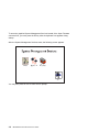
Chapter 3. System Management Services
Graphical System Management Services . .
Config . . . . . . . . . . . . . . . . . . . . . .
MultiBoot: . . . . . . . . . . . . . . . . . . . .
Utilities . . . . . . . . . . . . . . . . . . . . . .
Password . . . . . . . . . . . . . . . . . . . .
. . . . . . . . . . . . . . . . . . . .
Error Log
RIPL . . . . . . . . . . . . . . . . . . . . . . .
SCSI ID . . . . . . . . . . . . . . . . . . . . .
Update . . . . . . . . . . . . . . . . . . . . . .
Text-Based System Management Services .
Chapter 4. Service Processor Menus
Service Processor Menus . . . . . . . . .
General User Menus . . . . . . . . . . . .
Privileged User Menus . . . . . . . . . . .
Service Processor Functions and Features
IBM RS/6000 7025 F50 Series User's Guide
3-1
3-1
. 3-5
. 3-7
3-10
3-12
3-16
3-17
3-21
3-22
3-24
. . . . . . . . . . . . . . . . . . . . .
. . . . . . . . . . . . . . . . . . . . .
. . . . . . . . . . . . . . . . . . . .
. . . . . . . . . . . . . . . . . . . .
. . . . . . . . . . . . . . . . . . . .
. . . . . . . . . . . . . . . . . . . .
. . . . . . . . . . . . . . . . . . . .
. . . . . . . . . . . . . . . . . . . .
. . . . . . . . . . . . . . . . . . . .
. . . . . . . . . . . . . . . . . . . .
. . . . . . . . . . . . . . . . . . . .
4-1
4-3
. 4-4
. 4-6
4-24
. . . . . . . . . . . . . . . . . . . . . . .
. . . . . . . . . . . . . . . . . . . . . . .
. . . . . . . . . . . . . . . . . . . . . .
. . . . . . . . . . . . . . . . . . . . . .
. . . . . . . . . . . . . . . . . . . . .
Chapter 5. Installing Options
. . . . . . . . . . . . . . . . . . . . . .
Safety Considerations . . . . . . . . . . . . . . . . . . . . . . . . . . . .
Handling Static-Sensitive Devices . . . . . . . . . . . . . . . . . . . . .
Expansion Bays
. . . . . . . . . . . . . . . . . . . . . . . . . . . . . . .
Input/Output Connectors . . . . . . . . . . . . . . . . . . . . . . . . . . .
Removing the Front Covers Only
. . . . . . . . . . . . . . . . . . . . .
Removing Both the Front and Side Covers . . . . . . . . . . . . . . . .
Removing the I/O Planar Cover
. . . . . . . . . . . . . . . . . . . . . .
Option List . . . . . . . . . . . . . . . . . . . . . . . . . . . . . . . . . . .
Installing Memory . . . . . . . . . . . . . . . . . . . . . . . . . . . . . . .
Memory-Modules . . . . . . . . . . . . . . . . . . . . . . . . . . . . . . .
Removing Memory . . . . . . . . . . . . . . . . . . . . . . . . . . . . . .
Installing Adapters . . . . . . . . . . . . . . . . . . . . . . . . . . . . . .
Removing Adapters
. . . . . . . . . . . . . . . . . . . . . . . . . . . . .
Upgrading or Adding a CPU Card . . . . . . . . . . . . . . . . . . . . .
Installing Internal Drives . . . . . . . . . . . . . . . . . . . . . . . . . . .
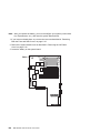
Installing a Disk Drive, Tape Drive, or CD-ROM in Bay A or Bay B . .
Installing a SCSI Disk Drive in Bank C, D, or E. . . . . . . . . . . . . .
Installing a SSA Disk Drive in Bank C, D, or E. . . . . . . . . . . . . .
Installing a SCSI Backplane in Bank D or E . . . . . . . . . . . . . . .
Installing a SSA Backplane in Bank D, or E . . . . . . . . . . . . . . .
Removing Internal Drives . . . . . . . . . . . . . . . . . . . . . . . . . .
Removing a Disk Drive, Tape Drive, or CD-ROM from Bay A or Bay B
Removing a SCSI Disk Drive from Bank C, D, or E . . . . . . . . . . .
iv
2-37
. . . . . . . . . . . . . . . . . . . . . . . . .
5-1
5-1
. 5-3
. 5-4
. 5-5
. 5-6
5-10
5-16
5-17
5-18
5-24
5-28
5-30
5-34
5-37
5-41
5-44
5-51
5-55
5-59
5-66
5-81
5-82
5-83
. . . . . .
. . . . . .
. . . . .
. . . . .
. . . . .
. . . . .
. . . . .
. . . . .
. . . . .
. . . . .
. . . . .
. . . . .
. . . . .
. . . . .
. . . . .
. . . . .
. . . . .
. . . . .
. . . . .
. . . . .
. . . . .
. . . . .
. . . .
. . . . .
Removing a SSA Disk Drive from Bank C, D, or E
Installing a U-Bolt . . . . . . . . . . . . . . . . . . .
Replacing the Front Covers . . . . . . . . . . . . .
Replacing Both the Front and Side Covers . . . .
Replacing the I/O Planar Cover
. . . . . . . . . .
. . . . . . . . . . . . . . . .
. . . . . . . . . . . . . . . . .
. . . . . . . . . . . . . . . . .
. . . . . . . . . . . . . . . . .
. . . . . . . . . . . . . . . .
Chapter 6. Using the Online and Standalone Diagnostics
Sources for the Diagnostics . . . . . . . . . . . . . . . . . . . .
Standalone and Online Diagnostics Operating Considerations
Online Diagnostics Modes of Operation . . . . . . . . . . . . .
Standalone Diagnostic Operation
. . . . . . . . . . . . . . . .
Location Codes . . . . . . . . . . . . . . . . . . . . . . . . . . .
Physical Location Codes
. . . . . . . . . . . . . . . . . . . . .
AIX and Physical Location Code Reference Table . . . . . . .
AIX Location Codes . . . . . . . . . . . . . . . . . . . . . . . .
5-87
5-91
5-93
5-96
5-101
6-1
6-1
. 6-1
. 6-9
6-12
6-14
6-14
6-15
6-20
. . . . . . . . . . .
. . . . . . . . . . .
. . . . . . . . . .
. . . . . . . . . .
. . . . . . . . . .
. . . . . . . . . .
. . . . . . . . . .
. . . . . . . . . .
. . . . . . . . . .
Chapter 7. Using the Service Aids . . . . . . . . . . . . . . . . . . . . . . . .
Introduction to Service Aids . . . . . . . . . . . . . . . . . . . . . . . . . . . . . .
AIX Shell Prompt Service Aid . . . . . . . . . . . . . . . . . . . . . . . . . . . . .
. . . . . . . . . . . . . . . . . . . . . . . . .
Backup/Restore Media Service Aid
Configure Remote Maintenance Policy Service Aid . . . . . . . . . . . . . . . .
Configure Ring Indicate Power On Policy Service Aid . . . . . . . . . . . . . . .
Configure Surveillance Policy Service Aid
. . . . . . . . . . . . . . . . . . . . .
Configure Reboot Policy Service Aid
. . . . . . . . . . . . . . . . . . . . . . . .
Save or Restore Hardware Management Policies Service Aid . . . . . . . . . .
Diagnostic Package Utility Service Aid
. . . . . . . . . . . . . . . . . . . . . . .
Dials and LPFK Configuration Service Aid . . . . . . . . . . . . . . . . . . . . .
Disk Based Diagnostic Update Service Aid and Update Disk Based Diagnostic
Task
. . . . . . . . . . . . . . . . . . . . . . . . . . . . . . . . . . . . . . . . . .
Disk Media Service Aids . . . . . . . . . . . . . . . . . . . . . . . . . . . . . . . .
Disk Maintenance Service Aid . . . . . . . . . . . . . . . . . . . . . . . . . . . .
Diskette Media Service Aid . . . . . . . . . . . . . . . . . . . . . . . . . . . . . .
Display or Change Configuration or Vital Product Data (VPD) Service Aid . . .
Display and Change Diagnostic Test List Service Aid . . . . . . . . . . . . . . .
Display Previous Diagnostic Results Service Aid
. . . . . . . . . . . . . . . . .
Display Test Patterns Service Aid . . . . . . . . . . . . . . . . . . . . . . . . . .
Enhanced SCSI Display Configuration Service Aid . . . . . . . . . . . . . . . .
Generic Microcode Download Service Aid
. . . . . . . . . . . . . . . . . . . . .
Hardware Error Report Service Aid and Display Hardware Error Log Task
. .
ISA Adapter Configuration Service Aid . . . . . . . . . . . . . . . . . . . . . . .
Machine Check Error Log Service Aid . . . . . . . . . . . . . . . . . . . . . . . .
Microcode Download Service Aid
. . . . . . . . . . . . . . . . . . . . . . . . . .
Periodic Diagnostics Service Aid . . . . . . . . . . . . . . . . . . . . . . . . . . .
SCSI Bus Analyzer Task
. . . . . . . . . . . . . . . . . . . . . . . . . . . . . . .
7-1
. 7-3
. 7-4
. 7-4
. 7-4
. 7-6
. 7-7
. 7-7
. 7-9
. 7-9
7-10
.
7-10
7-10
7-12
7-13
7-13
7-15
7-16
7-16
7-16
7-17
7-17
7-17
7-18
7-18
7-19
7-20
Preface
v
SCSI Tape Utilities Service Aid . . . . . . . . . . . . . .
Service Hints Service Aid . . . . . . . . . . . . . . . . .
Update System or Service Processor Flash Service Aid
Display Firmware Device Node . . . . . . . . . . . . . .
Display Resource Attributes . . . . . . . . . . . . . . . .
7135 RAIDant Array Service Aid . . . . . . . . . . . . .
PCI RAID Physical Disk Identify . . . . . . . . . . . . .
. . . . . . . . . . . . . .
. . . . . . . . . . . . . .
. . . . . . . . . . . . .
. . . . . . . . . . . . . .
. . . . . . . . . . . . . .
. . . . . . . . . . . . . .
. . . . . . . . . . . . . .
Chapter 8. Using the System Verification Procedure
Step 1. Considerations before Running This Procedure
Step 2. Loading the Diagnostics . . . . . . . . . . . . . .
Step 3. Running System Verification . . . . . . . . . . . .
Step 4. Additional System Verification . . . . . . . . . . .
Step 5. Stopping the Diagnostics . . . . . . . . . . . . . .
. . . . . . . . . . . . . .
. . . . . . . . . . . . . .
. . . . . . . . . . . . . .
. . . . . . . . . . . . . .
. . . . . . . . . . . . . .
. . . . . . . . . . . . . .
Chapter 9. Hardware Problem Determination . . . . . . . . . . .
Problem Determination Using the Standalone or Online Diagnostics
Problem Determination When Unable to Load Diagnostics . . . . .
Appendix A. System Records
Record the Identification Numbers
Device Records . . . . . . . . . .
. . . . . . .
. . . . . . . . . . . . . . . . . . . . . . . . . .
. . . . . . . . . . . . . . . . . . . . . . . . . . .
. . . . . . . . . . . . . . . . . . . . . . . .
Appendix C. Service Processor Setup and Test
Testing the Setup . . . . . . . . . . . . . . . . . . . .
Appendix D. Modem Configurations
Sample Modem Configuration Files . .
Configuration File Selection . . . . . . .
Seamless Transfer of a Modem Session
Modem Configuration Samples . . . . .
. . . . . . . . . . . . . . . .
. . . . . . . . . . . . . . . .
. . . . . . . . . . . . . . . . . . . . . . .
. . . . . . . . . . . . . . . . . . . . . . .
. . . . . . . . . . . . . . . . . . . . . . .
. . . . . . . . . . . . . . . . . . . . . .
. . . . . . . . . . . . . . . . . . . . . . .
Appendix E. Service Processor Operational Phases
8-1
8-1
8-2
8-3
8-3
8-4
9-1
9-1
9-10
A-1
A-1
A-2
B-1
C-1
C-2
D-1
D-1
D-2
D-6
D-9
. . . . . . . . . . . . .
E-1
. . . . . . . . . . . . . . . . . . . . . . . . . . . . . . . . . . . . . . . . . . .
X-1
Reader's Comments — We'd Like to Hear From You
vi
. . . . . . .
. . . . . . . . . . . . . . . . . . . . . . . . . . .
Appendix B. Replacing the Battery
Index
. . . . . . . .
7-22
7-23
7-23
7-24
7-24
7-25
7-25
IBM RS/6000 7025 F50 Series User's Guide
. . . . . . . . . . . . .
X-3
Communications Statements
Federal Communications Commission (FCC) Statement
Note: This equipment has been tested and found to comply with the limits for a
Class A digital device, pursuant to Part 15 of the FCC Rules. These limits are
designed to provide reasonable protection against harmful interference when the
equipment is operated in a commercial environment. This equipment generates,
uses, and can radiate radio frequency energy and, if not installed and used in
accordance with the instruction manual, may cause harmful interference to radio
communications. Operation of this equipment in a residential area is likely to cause
harmful interference in which case the user will be required to correct the
interference at his own expense.
Properly shielded and grounded cables and connectors must be used in order to
meet FCC emission limits. Neither the provider nor the manufacturer are responsible
for any radio or television interference caused by using other than recommended
cables and connectors or by unauthorized changes or modifications to this
equipment. Unauthorized changes or modifications could void the user's authority to
operate the equipment.
This device complies with Part 15 of the FCC Rules. Operation is subject to the
following two conditions: (1) this device may not cause harmful interference,and (2)
this device must accept any interference received, including interference that may
cause undesired operation.
International Electrotechnical Commission (IEC) Statement
This product has been designed and built to comply with IEC Standard 950.
United Kingdom Telecommunications Safety Requirements
This equipment is manufactured to the International Safety Standard EN60950 and
as such is approved in the UK under the General Approval Number
NS/G/1234/J/100003 for indirect connection to the public telecommunication network.
The network adapter interfaces housed within this equipment are approved
separately, each one having its own independent approval number. These interface
adapters, supplied by the manufacturer, do not use or contain excessive voltages. An
excessive voltage is one which exceeds 70.7 V peak ac or 120 V dc. They interface
with this equipment using Safe Extra Low Voltages only. In order to maintain the
separate (independent) approval of the manufacturer's adapters, it is essential that
Preface
vii
other optional cards, not supplied by the manufacturer, do not use main voltages or
any other excessive voltages. Seek advice from a competent engineer before
installing other adapters not supplied by the manufacturer.
European Union (EU) Statement
This product is in conformity with the protection requirements of EU Council Directive
89/336/EEC on the approximation of the laws of the Member States relating to
electromagnetic compatibility.
Neither the provider nor the manufacturer can accept responsibility for any failure to
satisfy the protection requirements resulting from a non–recommended modification
of the product, including the fitting of option cards not supplied by the manufacturer.
This product has been tested and found to comply with the limits for Class B
Information Technology Equipment according to CISPR 22 / European Standard EN
55022. The limits for Class B equipment were derived for typical residential
environments to provide reasonable protection against interference with licensed
communication devices.
Avis de conformité aux normes du ministère des Communications du
Canada
Cet appareil numérique de la classe A respecte toutes les exigences du Réglement
sur le matériel brouilleur du Canada.
Canadian Department of Communications Compliance Statement
This Class A digital apparatus meets the requirements of the Canadian
Interference–Causing Equipment Regulations.
VCCI Statement
The following is a summary of the VCCI Japanese statement in the box above.
viii
IBM RS/6000 7025 F50 Series User's Guide
This is a Class B product based on the standard of the Voluntary Control Council for
Interference from Information Technology Equipment (VCCI). If this is used near a
radio or television receiver in a domestic environment, it may cause radio
interference. Install and use the equipment according to the instruction manual.
When used near a radio or TV receiver, it may become the cause of radio
interference.
Read the instructions for correct handling.
Radio Protection for Germany
Dieses Gerät ist berechtigt in Übereinstimmung mit dem deutschen EMVG vom
9.Nov.92 das EG–Konformitätszeichen zu führen.
Der Aussteller der Konformitätserklärung ist die IBM Germany.
Dieses Gerät erfüllt die Bedingungen der EN 55022 Klasse B.
Preface
ix
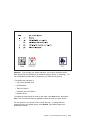
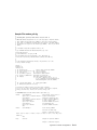
Note: If any of the following Feature Codes are installed:
3615, 4356, 4357, 4358, 4359, 6218, 8130, or 8134,
or if a configuration using more than one SysKonnect FDDI adapter (Feature
Codes 2741, 2742, or 2743) where any one of them is Feature Code 2743
(SysKonnect SK-NET FDDI-UP SAS PCI), the following statement applies:
European Union (EU) Statement
This product is in conformity with the protection requirements of EU Council Directive
89/336/EEC on the approximation of the laws of the Member States relating to
electromagnetic compatibility. The manufacturer cannot accept responsibility for any
failure to satisfy the protection requirements resulting from a non-recommended
modification of the product, including the fitting of option cards supplied by third
parties. Consult with your dealer or sales representative for details on your specific
hardware.
This product has been tested and found to comply with the limits for Class A
Information Technology Equipment according to CISPR 22 / European Standard EN
55022. The limits for Class A equipment were derived for commercial and industrial
environments to provide reasonable protection against interference with licensed
communication equipment.
Attention: This is a Class A product. In a domestic environment this product may
cause radio interference in which case the user may be required to take adequate
measures.
VCCI Statement
The following is a summary of the VCCI Japanese statement in the box above.
This is a Class A product based on the standard of the Voluntary Control Council for
Interference by Information Technology Equipment (VCCI). If this equipment is used
in a domestic environment, radio disturbance may arise. When such trouble occurs,
the user may be required to take corrective actions.
x
IBM RS/6000 7025 F50 Series User's Guide
Safety Notices
A danger notice indicates the presence of a hazard that has the potential of causing
death or serious personal injury.
A caution notice indicates the presence of a hazard that has the potential of causing
moderate or minor personal injury.
Electrical Safety
Observe the following safety instructions any time you are connecting or
disconnecting devices attached to the workstation.
DANGER
An electrical outlet that is not correctly wired could place hazardous
voltage on metal parts of the system or the devices that attach to the
system. It is the responsibility of the customer to ensure that the outlet
is correctly wired and grounded to prevent an electrical shock.
Before installing or removing signal cables, ensure that the power
cables for the system unit and all attached devices are unplugged.
When adding or removing any additional devices to or from the system,
ensure that the power cables for those devices are unplugged before
the signal cables are connected. If possible, disconnect all power
cables from the existing system before you add a device.
Use one hand, when possible, to connect or disconnect signal cables
to prevent a possible shock from touching two surfaces with different
electrical potentials.
During an electrical storm, do not connect cables for display stations,
printers, telephones, or station protectors for communication lines.
CAUTION:
This product is equipped with a three–wire power cable and plug for the user's
safety. Use this power cable with a properly grounded electrical outlet to avoid
electrical shock.
Preface
xi
DANGER
To prevent electrical shock hazard, disconnect the power cable from
the electrical outlet before relocating the system.
xii
IBM RS/6000 7025 F50 Series User's Guide
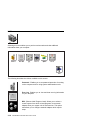
Laser Safety Information
The optical drive in this system unit is a laser product. The optical drive has a label
that identifies its classification. The label, located on the drive, is shown below.
CLASS 1 LASER PRODUCT
LASER KLASSE 1
LUOKAN 1 LASERLAITE
APPAREIL A LASER DE CLASSE 1
IEC 825:1984 CENELEC EN 60 825:1991
The optical drive in this system unit is certified in the U.S. to conform to the
requirements of the Department of Health and Human Services 21 Code of Federal
Regulations (DHHS 21 CFR) Subchapter J for Class 1 laser products. Elsewhere,
the drive is certified to conform to the requirements of the International
Electrotechnical Commission (IEC) 825 (1st edition 1984) and CENELEC EN 60
825:1991 for Class 1 laser products.
CAUTION:
A class 3 laser is contained in the device. Do not attempt to operate the drive
while it is disassembled. Do not attempt to open the covers of the drive as it
is not serviceable and is to be replaced as a unit.
Class 1 laser products are not considered to be hazardous. The optical drive
contains internally a Class 3B gallium-arsenide laser that is nominally 30 milliwatts at
830 nanometers. The design incorporates a combination of enclosures, electronics,
and redundant interlocks such that there is no exposure to laser radiation above a
Class 1 level during normal operation, user maintenance, or servicing conditions.
Preface
xiii
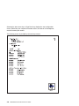
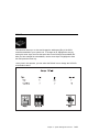
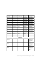
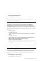
Power Cables
1
2
5
8
4
3
6
9
7
10
11
Index
Part Number
Country
1
1838574
Bahamas, Barbados, Bolivia, Brazil, Canada, Costa Rica,
Dominican Republic, El Salvador, Ecuador, Guatemala, Guyana,
Haiti, Honduras, Jamaica, Japan, Netherlands Antilles, Panama,
Peru, Philippines, Taiwan, Thailand, Trinidad, Tobago, U.S.A.
(except Chicago), Venezuela
2
6952300
Bahamas, Barbados, Bermuda, Bolivia, Brazil, Canada, Cayman
Islands, Colombia, Costa Rica, Dominican Republic, Ecuador, El
Salvador, Guatemala, Guyana, Haiti, Honduras, Jamaica, Japan,
Korea (South), Mexico, Netherlands Antilles, Nicaragua, Panama,
Peru, Philippines, Puerto Rico, Saudi Arabia, Suriname, Trinidad,
Taiwan, U.S.A. (except Chicago), Venezuela
2
62X1045
Chicago, U.S.A.
3
6952311
Argentina, Australia, New Zealand
4
13F9979
Abu Dhabi, Austria, Belgium, Bulgaria, Botswana, Egypt, Finland,
France, Germany, Greece, Iceland, Indonesia, Korea (South),
Lebanon, Luxembourg, Macau, Netherlands, Norway, Portugal,
Saudi Arabia, Spain, Sudan, Sweden, Turkey, Yugoslavia
5
13F9997
Denmark
6
14F0015
Bangladesh, Burma, Pakistan, South Africa, Sri Lanka
7
14F0033
Bahrain, Bermuda, Brunei, Channel Islands, Cyprus, Ghana,
Hong Kong, India, Iraq, Ireland, Jordan, Kenya, Kuwait, Malawi,
Malaysia, Nigeria, Oman, People's Republic of China, Qatar,
Sierra Leone, Singapore, Tanzania, Uganda, United Arab
Emirates (Dubai), United Kingdom, Zambia
xiv
IBM RS/6000 7025 F50 Series User's Guide
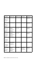
Index
Part Number
Country
8
14F0051
Liechtenstein, Switzerland
9
14F0069
Chile, Ethiopia, Italy
10
14F0087
Israel
11
6952291
Paraguay, Colombia, Uruguay
Preface
xv
xvi
IBM RS/6000 7025 F50 Series User's Guide
About This Book
This book provides information on how to install and remove options, use the
system, use diagnostics, use service aids, and verify system operation. This book
also provides information to help you solve some of the simpler problems that might
occur.
ISO 9000
ISO 9000 registered quality systems were used in the development and
manufacturing of this product.
Related Publications
The following publications are available:
The IBM RS/6000 7025 F50 Series Service Guide contains reference
information, maintenance analysis procedures (MAPs), error codes, removal and
replacement procedures, and a parts catalog.
The IBM RS/6000 Diagnostic Information for Multiple Bus Systems contains
diagnostic information, service request numbers (SRNs), and failing function
codes (FFCs).
The IBM RS/6000 Adapter, Device, and Cable Information for Multiple Bus
Systems contains information about adapters, devices, and cables for your
system. This manual is intended to supplement the service information found in
the IBM RS/6000 Diagnostic Information for Multiple Bus Systems.
The Site and Hardware Planning Information contains information to help you
plan your installation.
Trademarks
AIX is a registered trademark of the International Business Machines
Corporation.
PowerPC is a trademark of the International Business Machines Corporation.
Preface
xvii
xviii
IBM RS/6000 7025 F50 Series User's Guide
Chapter 1. System Startup
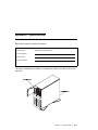
Thank you for selecting an IBM RS/6000 7025 F50 Series system!
The IBM RS/6000 7025 F50 Series system combines PowerPC 604 microprocessor
performance and system expandability, ensuring that your system adapts to handle
ever-changing operating requirements. The system is specifically designed to
support the demands of network environments.
The IBM RS/6000 7025 F50 Series system incorporates the new, advanced
peripheral component interconnect (PCI) bus, which is faster than the industry
standard architecture (ISA) bus. But the system also offers ISA as a additional bus
architecture, to accommodate businesses that already have invested in ISA and
ISA-based devices.
This book helps you set up and use the system, install and remove options,
configure the system, and use the system programs that are provided. This book
also provides information to help you solve some of the simpler problems that might
occur, and how to obtain assistance and service. Appendix A, “System Records” on
page A-1 provides a section for you to record all the important information about
your system.
Chapter 1. System Startup
1-1
Before You Begin
Make sure you have an adequate number of properly grounded electrical outlets
for your system, display, and any other options you intend to install.
Place your system in a location that is dry. Rain or spilled liquids might damage
your system.
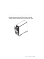
Always operate your system in the upright position and do not place any heavy
objects on top of your system.
Leave about 51 mm (2 in.) of space on all sides of the system to allow the
system's cooling system to work properly.
Collect the following tools, and keep them handy:
– Small flat-blade screwdriver
– Medium flat-blade screwdriver
– Trays to hold screws
Before continuing, refer to the System Unit Safety Information book for Danger
and Caution notices. Do not plug any cables into system unit, adapters, or
electrical outlets until you have reviewed this information.
Make sure none of the power cords are connected before continuing.
1-2
IBM RS/6000 7025 F50 Series User's Guide
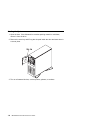
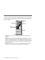
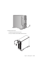
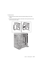
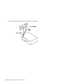
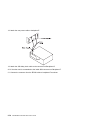
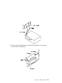
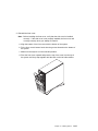
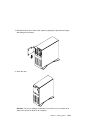
Unpacking Your System
CAUTION:
To avoid possible injury while moving or lifting the system, ask another person
to help you.
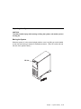
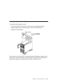
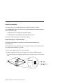
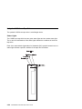
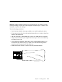
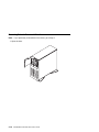
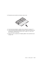
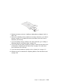
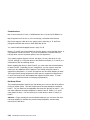
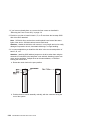
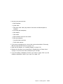
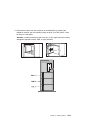
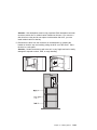
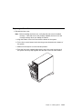
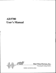
Moving the System
When the system is in the normal upright position, move it by lifting up on the handle
on the front and moving it forward or backward as shown. (There is a roller built into
the rear of the system's base.)
Chapter 1. System Startup
1-3
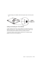
Preinstallation Checklist
After you unpack your system, display or ASCII terminal, and optional devices, make
sure you have the following items:
Ø
Ø
Ø
Ø
Ø
System and power cord
ASCII terminal (or keyboard, keyboard cable, display, display cable, and
display power cord)
Mouse (if using display and keyboard)
Other publications and media (for example, CD-ROM) that came with the
system
Options you want to install
Contact your authorized reseller or marketing representative if any items are missing
or damaged.
1-4
IBM RS/6000 7025 F50 Series User's Guide
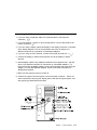
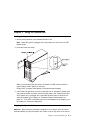
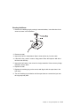
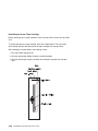
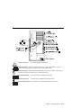
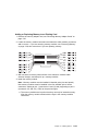
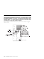
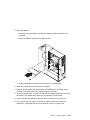
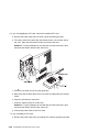
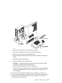
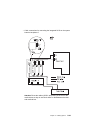
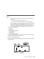
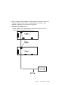
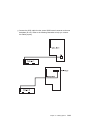
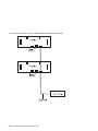
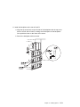
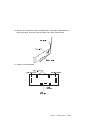
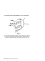
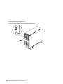
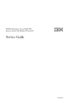
Connecting the Cables
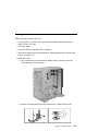
1. If you are using a keyboard, attach the keyboard cable to the keyboard
connector (
).
2. If you are installing a mouse or other pointing device, connect that cable to the
mouse connector ( ).
3. If you are using a display, attach the display to the display connector on the back
of the display adapter in one of the expansion slots. See the About Your
Machine document for information on preinstalled adapters.
4. If you are using an ASCII terminal, connect the terminal to serial port 1 (
).
5. Connect the display or ASCII terminal power cord to the display or ASCII
terminal.
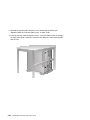
6. Attach adapter cables to any adapters installed in the expansion slots. See the
About Your Machine document for information on preinstalled adapters. For
more instructions on adapter cabling, see the documentation that came with your
adapter, or to the IBM RS/6000 Adapter, Device, and Cable Information for
Multiple Bus Systems.
7. Make sure the system's power is turned off.
8. Connect the system connector power cord to the power connector. Secure all
these connections, then plug the display power cord and the system power cord
into properly grounded electrical outlets.
Chapter 1. System Startup
1-5
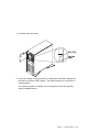
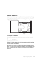
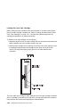
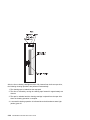
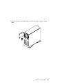
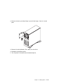
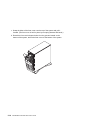
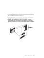
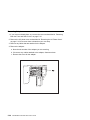
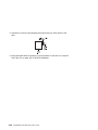
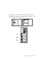
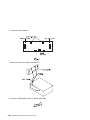
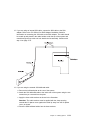
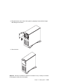
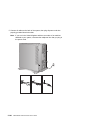
Starting the System
1. Open the door. If the diskette drive contains packing material or a diskette,
remove it from the drive.
2. Remove the extra key and ID tag that is taped inside the door and store them in
a secure place.
3. Turn on all external devices, such as printers, plotters, or modems.
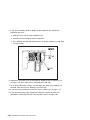
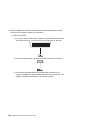
1-6
IBM RS/6000 7025 F50 Series User's Guide
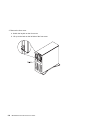
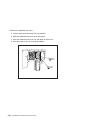
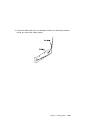
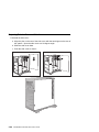
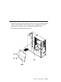
4. Press the Power On switch.
5. Check your display or ASCII terminal for configuration information displayed as
the power-on self-test (POST) begins. The system beeps once to indicate it is
working properly.
If no operating system is installed, you are prompted to select the operating
system installation device.
Chapter 1. System Startup
1-7
Finishing the Installation
Important
Be sure to maintain at least 51 mm (2 in.) of space on all sides of the system
to allow the system's cooling system to work properly. Blocking the air vents
can cause overheating, which might result in a malfunction or permanent
damage.
Your system hardware is set up, and you are ready to learn about your system and
make backup copies of important software. The order in which you do these tasks is
up to you. Use the following checklist as a guide.
Ø
Record your identification numbers
Your system has important identification information that you might need if you
have it serviced. Appendix A, “System Records” on page A-1 shows where to
find these numbers, and provides space to record and retain this information.
Ø
Install options
If you decided earlier to delay installing your options, you might want to
complete these installations now. See Chapter 5, “Installing Options” on
page 5-1 for handling and installation instructions.
Ø
Install the Operating System
If AIX is preinstalled in your system unit, or if you plan to install AIX yourself,
refer to the Quick Installation and Startup Guide for instructions.
Some options that you might install come with a diskette that contains device
drivers, configuration files, or test programs. To install these files (after your
operating system is installed), follow the instructions that come with the
diskettes.
Ø
Install application programs
To install application programs, follow the instructions supplied with each
application program.
1-8
IBM RS/6000 7025 F50 Series User's Guide
Chapter 2. Using the System Unit
Starting the System Unit
1. Set the power switches of the attached devices to On.
Note: When the system is plugged in but not powered on, the Power On LED
flashes slowly.
2. Press the Power On switch.
When you press the Power On switch, the Power On LED comes on and the
system starts a POST (power-on self test).
During POST, progress codes display in the operator panel display.
3. If the Power On light does not come on and there is no indication of power when
you press the Power On switch, ensure that the power cord, located at the back
of the system unit, is plugged into a grounded electrical outlet. If this does not
solve the problem, go to Chapter 9, “Hardware Problem Determination” on
page 9-1. If the LED is not flashing and OK is not displayed in the display, go to
the section on running the diagnostics.
Stopping the System Unit
Attention: When using the shutdown procedure for your system, enter the correct
command before you stop the system unit. Failure to do so may result in the loss of
Chapter 2. Using the System Unit
2-1
data. If you need information on the shutdown procedure for your operating system,
see your operating system documentation.
1. Before stopping the system unit, you must first perform a shutdown procedure of
the operating system to prevent the loss of data.
2. After you shut down the operating system, set the power switches of the
attached devices to Off.
3. The system unit is powered down by the shut down procedure.
2-2
IBM RS/6000 7025 F50 Series User's Guide
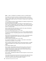
Reading the Operator Panel Display
The operator panel display is used to:
Track the progress of the system unit self tests and configuration program.
Display codes when the operating system comes to an abnormal end.
Display system messages.
During power-on self-test (POST), 4 characters display indicating the progress of the
testing. If an error is detected that requires attention, the system unit halts and an 8
digit number displays in the operator panel display to identify the error.
Chapter 2. Using the System Unit
2-3
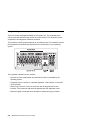
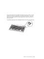
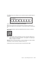
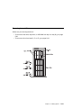
Using the Keyboards
There are several keyboards available for the system unit. The keyboards have
various keys that enter data and control the cursor location. The keyboards can be
engraved for the languages of different countries.
The functions of each keyboard depend on the software used. The character sets for
the keyboards are contained and explained in the information for your operating
system.
The keyboard is divided into four sections:
Function keys are multipurpose keys and their function is controlled by the
operating system.
Typewriter keys are similar to a standard typewriter. Their function is controlled
by the software.
Control keys move the cursor on the screen and do programmed control
functions. The movement and functions depend upon the application used.
Numeric keypad is arranged like a calculator to help when typing numbers.
2-4
IBM RS/6000 7025 F50 Series User's Guide
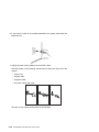
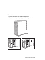
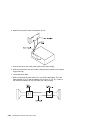
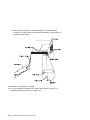
On all of the keyboards, you can adjust the tilt position for typing comfort. To tilt the
keyboard, pull out on the keyboard legs. The legs snap into position. To decrease
the tilt of the keyboard, rotate the keyboard legs until they snap into the bottom of
the keyboard case.
The keyboard cable plugs into the keyboard connector at the rear of the system unit.
Chapter 2. Using the System Unit
2-5
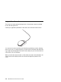
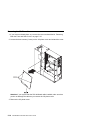
Using the Three–Button Mouse
The mouse is a hand–operated locating device. A three–button mouse is available
for use with the system unit.
Consult your application publication for the exact use of the three–button mouse.
You can use the mouse to perform such functions as positioning a cursor, selecting
items from a menu, or moving around in your document much easier and faster than
if you used only the keyboard. The cursor moves exactly as you move the mouse on
a flat surface, such as a desktop.
When you move the mouse around on a flat surface as shown in this illustration, the
cursor moves on the display screen; the movement changes the position of the
cursor.
2-6
IBM RS/6000 7025 F50 Series User's Guide
With the mouse buttons, you can perform functions such as selecting and
deselecting options, extending your selection, or choosing a command. The precise
function of your mouse depends on the software you are using.
The mouse has a cable that plugs into the mouse connector at the rear of the
system unit.
Handling the Mouse Correctly
For best operation, handle the mouse with care. Incorrect handling can damage the
mouse.
Do not:
Operate the mouse on cloth, unfinished wood, newspaper, or carpet.
Drop or hit the mouse.
Carry the mouse by holding onto the cable.
Expose the mouse to extreme temperatures or direct sunlight.
Place the mouse in liquid spills.
Chapter 2. Using the System Unit
2-7
Care of the Mouse
The operating surface for the mouse should be smooth, clean, and flat. For
example, you can operate the mouse on the following surfaces:
Finished wood
Glass
Enamel
Plastic
Paper (except newspaper)
Metal
Rough surfaces collect contaminants that can be transferred to the interior of the
mouse by the ball. The surface you use should be free from spills, dirt, dust, lint,
wax, eraser dust, and other foreign matter. Rough surfaces can also cause the pads
located on the bottom of the mouse to prematurely wear. A deeply pitted surface
could cause erratic operation of the mouse.
Inspect the work surface for spills or other contaminants.
Dust the work surface.
If you are using a paper pad, inspect it for wear and replace it if necessary.
2-8
IBM RS/6000 7025 F50 Series User's Guide
Cleaning the Mouse
1. Remove the retaining ring by turning it counterclockwise, in the direction of the
arrow as shown in the illustration.
2. Remove the ball.
3. Inspect the ball for contaminants. Wipe it clean with a dry, lint–free cloth.
4. If the ball is dirty, wash it in warm, soapy water. Rinse and wipe the ball with a
lint–free cloth until dry.
5. Inspect the ball cavity in the mouse for foreign materials. If there are any foreign
materials, remove them.
6. Replace the ball.
7. Replace the retaining ring on the mouse and align it with the open slots in the
ball cavity.
8. Turn the retaining ring clockwise until the open slots are covered and you hear
the ring snap into place.
Chapter 2. Using the System Unit
2-9
Using the 3.5–Inch Diskette Drive
Diskette Compatibility
The system unit has a 1.44MB diskette drive installed vertically in the front.
The 1.44MB diskette drive can format, read, and write diskettes compatible with the
following diskette drives:
1.0MB diskettes with 720KB formatted data capacity.
2.0MB diskettes with 1.44MB formatted data capacity (HD).
Format the diskette according to its specified capacity.
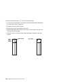
Write–Protecting 3.5–Inch Diskettes
Write–protecting diskettes is necessary so that important information is not
accidentally lost.
When diskettes are write–protected, you can read information from the diskettes, but
you cannot write information on to them.
There is a write–protect tab on the 3.5–inch diskette.
To locate the write–protect tab, turn the diskette over with the label facing down.
To prevent writing onto a diskette, slide the write–protect tab, to open the protect
slot.
2-10
IBM RS/6000 7025 F50 Series User's Guide
To allow writing onto a diskette, slide the write–protect tab to cover the protect
slot.
Loading and Unloading the 3.5–Inch Diskette
To load a diskette into the drive, insert the diskette in the diskette drive with the
labeled metal shutter first. Push the diskette into the drive until you hear a click.
The click indicates that the diskette is securely in position in the drive.
To unload the diskette, push the diskette–unload button. The diskette unloads
partially from the drive. Pull the diskette out.
Chapter 2. Using the System Unit
2-11
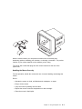
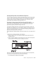
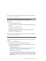
Using the CD–ROM Drive
CAUTION:
A Class 3 laser is contained in the device. Do not attempt to operate the device
while it is disassembled. Do not attempt to open the covers of the device, as it
is not serviceable and is to be replaced as a unit.
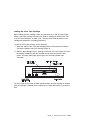
The CD–ROM is located in bay A1 of the system unit, see page 2-15. Your
CD–ROM drive looks like the one shown in the illustration, and the controls are
located as indicated.
When the CD–ROM is set to On, the status light indicates one of several conditions.
The following are status light states and the respective conditions of the CD–ROM
drive:
Off during standby with the tray loaded or unloaded.
Blinks from insertion of the tray to completion of initialization.
Blinks slowly when disc is dusty.
Blinks fast when in the audio mode.
Lights during data transfer operations.
Lights steady when:
– No disc is in the tray.
– The disc is in the tray upside down.
– Some condition exists that should be checked. If this occurs, contact your
service representative.
2-12
IBM RS/6000 7025 F50 Series User's Guide
Loading the CD–ROM Drive
Press the unload button to open the tray. Place the disc, with the printed side away
from the tray, into the tray. Slip out the bottom tabs to hold the disc in place. Push
gently on the load/unload button. The drive automatically pulls the tray into the drive
and prepares the disc for reading.
Unloading the CD–ROM Drive
Push and hold the unload button until the drawer comes out and then remove the
disc.
Cleaning the CD–ROM Drive
This CD–ROM drive has an internal head–cleaning mechanism, and therefore does
not require an external cleaning device. The internal cleaning mechanism cleans the
head every time the tray is operated.
Always handle discs carefully by the edges to avoid leaving fingerprints or scratching
the disc. (This helps the disc to maintain good readability.) Discs can be wiped with a
soft, lint–free cloth or lens tissue. Always wipe in a straight line from the inner hub to
the outer rim.
Chapter 2. Using the System Unit
2-13
Emergency Eject
Note: Execute the following procedure only in an emergency (tray will not eject
although pressing the unload button).
1. Insert a small diameter rod, such as a straightened paper clip, into the
emergency eject hole. (Refer to the illustration below for the location of the
emergency eject hole.)
2. Push the tool in until some resistance is felt.
3. Maintain a small amount of pressure on the rod while pulling on the tray with
your finger nail.
4. Pull the tray open and remove the disc.
Note: Normally the tray makes a ratcheting sound when pulling it open using the
above procedure.
2-14
IBM RS/6000 7025 F50 Series User's Guide
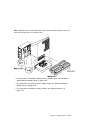
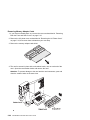
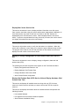
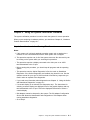
Using the Hot Swap Disk Drives
For information on installing hot swap drives refer to “Installing a SCSI Disk Drive in
Bank C, D, or E.” on page 5-51.
For information on removing hot swap drives refer to “Removing a SCSI Disk Drive
from Bank C, D, or E” on page 5-83.
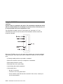
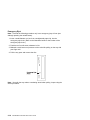
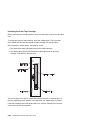
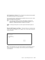
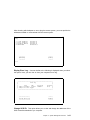
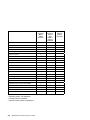
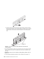
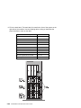
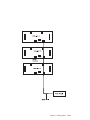
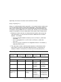
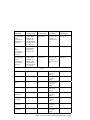
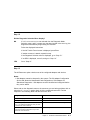
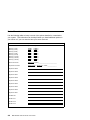
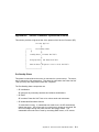
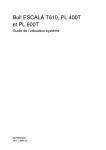
Relationship of AIX Prompts and Physical Drive Location
A SCSI adapter and a SCSI drive address can be displayed on a user display. The
AIX command lscfg list the attached devices on the system display. A SCSI adapter
and drives might be listed as:
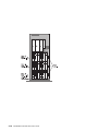
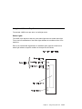
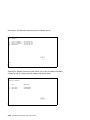
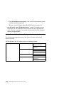
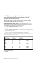
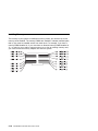
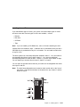
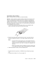
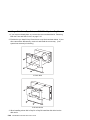
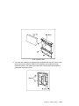
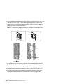
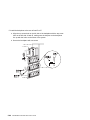
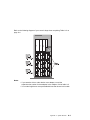
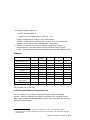
Labels on the right side of each bank, identify the PCI Bus indicator and PCI Slot
address for the SCSI adapter attached to each bank.
Physical Slot of SCSI Adapter
Bank Label
9I/P
30 - 78
8I/P
30 - 70
7P
30 - 68
6P
30 - 60
5P
10 - 78
4P
10 - 70
3P
10 - 68
2P
20 - 60
1P
20 - 58
Second Integrated SCSI Controller
30 - 58
First Integrated SCSI Controller
10 - 60
Chapter 2. Using the System Unit
2-15
2-16
IBM RS/6000 7025 F50 Series User's Guide
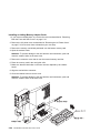
Handling Guidelines
The hot-swap disk drive is a sensitive device. Handle the hot-swap carrier and disk
drive with care.
Do not drop the disk drive or subject the drive to excessive shock.
Do not expose the disk drive to temperatures lower than -40° F (-40° C) or
higher than 158 ° F (70° C).
If drive temperature changes, allow approximately one hour of temperature
acclimatization for every 18° F (10° C) of temperature change.
Never allow moisture to condense on the drive.
Static electricity can damage your equipment. Take these precautions to avoid
static electricity damage:
– Always handle your disk drive carefully.
– Handle the drive by the edges and never touch any exposed circuitry.
– Prevent others from touching the drive.
Store the hot-swap disk drive in a protective container such as an instrument
case or in a protected area.
Failure to observe these precautions may lead to product failure, damage, and
invalidation of all warranties.
Media can take as link as 30 seconds to spin down. Make sure that there is at
least a 30 second delay before switching off the hot-swap drives for removal.
Labels
Several labels are included in your system ship group which may be attached to the
handle of the hot-swap drive. The labels may be marked in any way that the user
can easily identify the drive for removal or installation.
Chapter 2. Using the System Unit
2-17
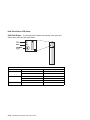
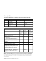
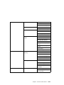
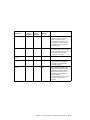
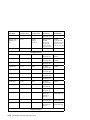
Disk Drive Status LED States
SCSI Disk Drives: The following table explains the meaning of the green and
amber status LEDs and spin down button.
Status LEDs
LED or Button
Status
Definition
Amber
On
Drive spinning
Off
Drive not spinning
On
Power On
Off
Power Off
Blinking
Power Off/Drive identify
Depressed
Spin down drive and remove power
Green
Spin down
2-18
IBM RS/6000 7025 F50 Series User's Guide
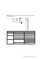
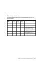
SSA Disk Drives: The following table explains the meaning of the Power, Ready
and Check status LEDs.
Status LEDs
LED
Status
Definition
Power
On
Power On
Off
Power Off
On
Both SSA connections good and
drive is ready
Blinking
Only one SSA connection good
Flickering
Drive is executing a command
On
Disk drive failure
Ready
Check
Self-test running
Drive in service mode
Blinking
Disk drive selected
Chapter 2. Using the System Unit
2-19
General Information for 8-mm Tape Drive
Recommendations
Use only Data Grade 8-mm tape cartridges. These cartridges are identified by
either a Data, D, or D8 marking on the data cartridge. Use of video grade
cartridges can damage the 8-mm tape drive and can void the warranty of your
8-mm tape drive, and data written on these tapes may be lost over a short period
of time.
Remove the tape cartridge from the tape drive when it is not in use, and store
the cartridge in the cartridge case.
Do not open the door on the data tape cartridge. This door covers and protects
the magnetic tape material from dirt, dust, and damage.
Avoid touching the tape since this can cause loss of data.
Keep the tape drive door closed except when loading or unloading a tape
cartridge.
Back up and then discard any tape cartridge that repeatedly produces error
messages. The error information is in the system error log.
Clean the tape path regularly according to the cleaning procedure of the 8-mm
tape drive. Use only recommended cleaning cartridges; other cleaning cartridges
can permanently damage your 8-mm tape drive.
Attention: Do not use video grade cartridges in the 8-mm tape drive. Video grade
tapes may be unreliable and may cause permanent damage to the 8-mm tape drive.
Types of 8-mm Tape Cartridges
Test Tape Cartridge: This is a specially labeled tape cartridge that is in the
media kit with the 8-mm tape drive. Use this cartridge only when checking the
operation of the drive or running diagnostics; do not use it to save programs or
data.
Data Tape Cartridge: This is a non-labeled blank tape cartridge that is in the
media kit. Use this cartridge for saving your programs or data. The same data
tape cartridge can be used in either a 2.3GB 8-mm tape drive or a 5.0GB 8-mm
tape drive.
Cleaning Tape Cartridge: Use this cartridge for cleaning the 8-mm tape path. For
more information, see “Cleaning the Tape Path on the 5.0GB 8-mm Tape Drive”
on page 2-29.
2-20
IBM RS/6000 7025 F50 Series User's Guide
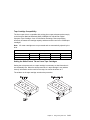
Tape Cartridge Compatibility
The 8-mm tape drive is compatible with existing 8-mm tape subsystems that comply
to the American National Standard (ANSI) X3B5/89-136, Helical-scan Digital
Computer Tape Cartridge, 8-mm for Information Exchange. Data compression
effectively increases the cartridge capacity and data transfer rate for the 5.0GB tape
cartridges.
Note: 160 meter cartridges are not processed and are automatically ejected by the
drive.
Format Modes (C=compression mode)
8-mm Tape Drive
2.3GB
2.3GB
Read/Write
5.0GB
Read/Write
2.3GB (C)
5.0GB
5.0GB (C)
Read only
Read/Write
Read/Write
Setting the Write-Protect Tab on 8-mm Tape Cartridges
Setting the write-protect tab on a tape cartridge is necessary so that information is
not accidentally lost. When the write-protect tab of a tape cartridge is set (window
closed), information can be read from the tape, but cannot be written to it.
The window on the tape cartridge controls write-protection.
Chapter 2. Using the System Unit
2-21
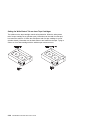
Environment Considerations for 8-mm Data Cartridges
Information in this section describes operating and storage conditions including
temperature, relative humidity, and maximum wet bulb data.
Attention: The manufacturer has specified a set of temperature and humidity
ranges in which the 8-mm data cartridge can operate with ease. Only regular
cleaning procedures are required when operating the cartridge within this range. The
risk of possible data loss is increased if 8-mm tape cartridges are operated, stored,
or shipped outside the temperature or humidity ranges shown in the following table.
Before using a cartridge, always let it adjust (acclimate) to the operating
environment. Do this by placing the cartridge with its container in the operating
environment for as long as it has been away from this environment or for 24 hours,
whichever is less.
Acclimation is necessary for any data cartridge that has been exposed to a different
humidity environment or a temperature change of 11°C or 20°F or more.
Temperature
Relative Humidity
(non-condensing)
Maximum Wet Bulb
2-22
Operating Ranges
Storage
Shipping
16°C to 32°C
(60°F to 90°F)
20 to 80%
5°C to 32°C
(40°F to 90°F)
20 to 80%
-40°C to 52°C
(-40°F to 125°F)
5 to 80%
26°C (79°F)
26°C (79°F)
26°C (79°F)
IBM RS/6000 7025 F50 Series User's Guide
Operating in Harsh Environments
The 8-mm tape drive is ideally suited to streaming operations, as opposed to tape
movement operations involving multiple stop/starts and random searches. When the
tape is used for frequent stop and start operations, streaming movement is beneficial
and should be used whenever possible. This can be accomplished by ensuring that
any save or restore operation is the only active operation performed by a device
connected to this SCSI I/O controller.
Any tape that has been used outside the ranges specified in the table on 2-22 for an
extended period of time (50 passes in 40 hours of nonstop operation) should not be
used as an archival tape. Exposure to the environment will deteriorate the magnetic
and physical strength of the tape. Do not store important data on a tape that has
been used outside the specified ranges; transfer the data to a new tape for reliable
archiving.
8-mm Data Cartridge Erasure
Most bulk eraser devices do not have the capability to erase 8-mm data cartridges.
To properly erase an 8-mm data cartridge with a bulk eraser device, the erasure
rating must be at least 1500 oersted.
The 2.3GB and the 5.0GB 8-mm tape drives erase residual data before writing new
data on the data tape.
Tape Cartridge Data Efficiency
The 8-mm tape cartridge efficiency is defined as the amount of data that can be
stored on the cartridge. The following variables affect the amount of data that can be
stored on a tape cartridge:
Size of the data file
Number of file marks per file
File mark size used
Compatibility mode (2.3GB or 5.0GB)
Media rewrites.
Chapter 2. Using the System Unit
2-23
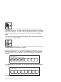
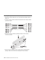
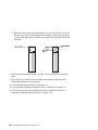
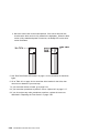
Using the 5.0GB 8-mm Tape Drive
The optional 5.0GB 8-mm tape drive is a half-height device.
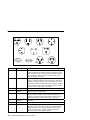
Status Lights
The 5.0GB 8-mm tape drive has two green status lights and one amber status light.
The on and off combinations of the status lights indicate the conditions of the 8-mm
tape drive.
Each of the International Organization for Standards (ISO) symbols located next to a
status light indicates a specific condition of the tape drive as follows:
2-24
IBM RS/6000 7025 F50 Series User's Guide
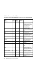
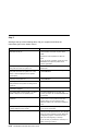
Status Light States
The following table explains the meaning of the green and amber status lights.
Status Lights on the 5.0GB 8-mm Tape Drive
Status
Ready
(green)
Busy
(green)
Disturbance
(amber)
The power-on self-test (POST) is running or the
system has issued a Reset to the drive.
On
On
On
One of the following has occurred:
Off
Off
Off or On
A tape cartridge has been inserted and the 8-mm
tape drive is ready to receive commands from the
system.
On
Off
Off or On
A tape cartridge has been inserted and the 8-mm
tape drive is performing a tape load or unload
operation.
Off
Flashing
Off or On
The tape is in motion and the 8-mm tape drive is
busy running a device operation.
On
Flashing
Off or On
The 8-mm tape drive has detected an internal
fault that requires corrective action. If this occurs,
see the following note.
Off
Off
Flashing
The tape path requires cleaning. Refer to
“Cleaning the Tape Path on the 5.0GB 8-mm
Tape Drive” on page 2-29.
Off or On
Off or
Flashing
On
The power is off.
The POST has completed successfully, but
no tape cartridge has been inserted.
Note: If a fault or an error condition occurs, first try to recover by pressing the
unload button. If this does not correct the fault, switch off the power to the 8-mm
tape drive and then switch on the power to the drive. If the condition continues, call
your service representative.
Chapter 2. Using the System Unit
2-25
Loading the 8-mm Tape Cartridge
Before loading the tape cartridge, make sure the power is on and the write-protect
tab on the tape cartridge is properly set. Refer to “Setting the Write-Protect Tab on
8-mm Tape Cartridges” on page 2-21. The tape drive loads the tape from the
cartridge and prepares it for reading and writing.
To load the 8-mm tape cartridge, do the following:
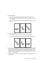
1. Grasp the edges of the 8-mm tape cartridge with the write-protect tab toward you
and the window side of the cartridge facing to the right.
2. Slide the tape cartridge into the opening on the front of the 8-mm tape drive until
the loading mechanism pulls the cartridge into the drive and the drive door
closes. The ready status light (green) goes on if the load operation was
successful.
The 8-mm tape drive is ready for data operations when the tape cartridge is inserted.
After the cartridge is inserted into the tape drive, the tape takes about 25 seconds to
load; this does not interfere with beginning the data operations.
2-26
IBM RS/6000 7025 F50 Series User's Guide
Commands can be entered while the tape is loading. Any commands to the tape
drive start running once the tape has finished loading. Commands not requiring the
tape cartridge are run immediately.
Chapter 2. Using the System Unit
2-27
Unloading the 8-mm Tape Cartridge
Before performing the unload operation, make sure the power to the 8-mm tape drive
is on.
To unload and eject the tape cartridge, press the unload button. The 8-mm tape
drive rewinds the tape and then ejects the tape cartridge from the tape drive.
After pressing the unload button, the following occurs:
1. The ready status light goes off.
2. The busy status light flashes during the unload operation.
3. The busy status light will goes off when the cartridge is ejected from the tape
drive.
2-28
IBM RS/6000 7025 F50 Series User's Guide
The time required for a tape to rewind and unload is between 18 seconds and 3
minutes, depending on the position of the tape when the unload button is pushed.
If the tape cartridge cannot unload and has to be removed manually from the drive,
contact your service representative.
Cleaning the Tape Path on the 5.0GB 8-mm Tape Drive
Attention: Do not use video cleaning cartridges in the 8-mm tape drive. Video
cleaning cartridges can damage the 8-mm tape drive.
The 8-mm tape path should be cleaned either approximately every 30 hours of tape
motion or once a month, whichever occurs first. The 5.0GB 8-mm tape drive counts
the number of hours of tape motion and indicates when the tape path requires
cleaning when the lighted disturbance status light (amber) is on.
More frequent cleaning may be required if the drive is operated in a dusty
environment or in humid conditions. If the dust is allowed to accumulate, the drive
has to perform more reads and writes. This can cause data loss, and may be
prevented by regularly scheduled cleaning of the drive.
The cleaning cartridge cleans the 8-mm tape drive. If you attempt to use an 8-mm
cleaning cartridge more times than allowed, the tape drive automatically detects the
error and ejects the cleaning cartridge. The disturbance status light (amber) remains
on if it was on prior to the cleaning operation being attempted.
Some video cleaning cartridges are extremely abrasive. An 8-mm tape drive may be
permanently damaged after only a few cleaning operations using an abrasive-type
cleaning cartridge.
Before loading the cleaning cartridge, make sure the power to the 8-mm tape drive is
on.
To load the 8-mm cleaning cartridge, do the following:
1. Grasp the edges of the 8-mm cleaning cartridge with the window side of the
cartridge facing to the right.
2. Slide the cleaning cartridge into the opening on the front of the 8-mm tape drive
until the loading mechanism pulls the cartridge into the drive.
Chapter 2. Using the System Unit
2-29
After the 8-mm cleaning cartridge has been fully inserted into the 8-mm tape drive,
the following cleaning operations are performed automatically:
1. The cleaning tape is loaded into the tape path.
2. The drive is cleaned by moving the cleaning tape forward for approximately two
minutes.
3. The tape is unloaded and the cleaning cartridge is ejected from the tape drive
when the cleaning operation is complete.
4. A successful cleaning operation is indicated when the disturbance status light
(amber) goes off.
2-30
IBM RS/6000 7025 F50 Series User's Guide
General Information for 4.0GB 4-mm Tape Drive
The 4.0GB 4-mm tape drive is a streaming tape drive that is used to:
Save and restore system data files.
Archive important records.
Distribute operating system software upgrades.
The 4-mm tape drive can be attached to any system using a single-ended interface
meeting the Small Computer System Interface ll (SCSI-ll) Standard ANSI
X3.131-199X Rev. 10h.
The 4-mm tape drive has the following features:
Capacity of 4.0 GB per cartridge. 8 GB is typical with data compression and with
DDS2 data cartridges.
The actual capacity per cartridge varies depending on the application and the
type of data cartridge being used.
Data transfer rate is 400 KBps. 800 KBps is typical with data compression.
Note: Data compression activated is the default setting from the factory. Data
compression is usually controlled by the application software.
Read and write of DDS|||| tape cartridges in 2.0 GB per cartridge format.
A status light that indicates when it is time to clean the tape path.
Internal diagnostics that are activated when the 4 mm Diagnostic Cartridge is
inserted and loaded into the drive.
Media recognition system: only data grade media can be written with this tape
drive.
The 4-mm tape drive uses a 4-mm data cartridge for saving and restoring your
system data. The 4-mm tape drive writes and reads only 4-mm Digital Data Storage
(DDS|||| or DDS2) cartridges.
Chapter 2. Using the System Unit
2-31
Recommendations
Attention: Tape cartridges that do not carry the proper DDS symbol cannot be
written to and their use may cause the 4-mm tape drive to report an error.
Use only 4-mm Digital Data Storage (DDS|||| or DDS2) cartridges.
Attention: Use of other than recommended cleaning cartridges can damage
your tape drive and will void the drive warranty.
Clean the tape path by using the recommended cleaning cartridge. Follow the
instructions on the cartridge.
Back up and then discard any tape cartridge that repeatedly produces error
messages. The error information is in the system error log.
Do not open the door on the data cartridge that covers the tape. This door
protects the magnetic tape material from dirt, dust, and damage.
Do not operate in a dusty environment.
Do not touch the tape material. Any substance transferred to the tape by
touching it could cause loss of data.
Types of 4-mm Tape Cartridges
The 4-mm tape drive is shipped with three 4-mm cartridges to help start your tape
operations immediately.
4-mm Data Cartridge:
Use this non-labeled cartridge for saving or
restoring your programs or data. Additional data
cartridges can be ordered.
4-mm Diagnostic Cartridge:
Use this specially labeled cartridge to perform
diagnostics on the drive. Do not use it to save or
restore programs or data.
Cleaning Cartridge:
Use this cartridge for cleaning the 4-mm tape path.
For more information, see “Cleaning the Tape Path
on the 4.0GB 4-mm Tape Drive” on page 2-41.
2-32
IBM RS/6000 7025 F50 Series User's Guide
Tape Cartridge Compatibility
The 4-mm Tape Drive is compatible with existing 4mm tape subsystems that are
designed to operate with Digital Data Storage approved media, which meet the
following standards:
For DDS||||
– American National Standard (ANSI) standard, X3.203-191, Helical-scan
Digital Computer Tape Cartridge, 3.81mm.
– European Computer Manufacturers Association (EMCA) standard,
EMCA-150 , 3.81mm Wide Magnetic Tape Cartridge and DDS|||| format.
For DDS2
– European Computer Manufacturers Association (EMCA) standard,
EMCA/TC17/93/20, 3.81mm Wide Magnetic Tape Cartridge for Information
Interchange Helical Scan Recording, DDS2 format.
You cannot change the density setting of the drive, because the device reconfigures
itself automatically, depending on the media type installed, as follows:
Media Type
Device Configuration
Non-DDS
Read-only
DDS||||
Read/write in 2.0GB mode only.
DDS2
Read in either density; write in 4.0GB mode only.
Chapter 2. Using the System Unit
2-33
Setting the Write-Protect Tab on 4-mm Tape Cartridges
The window on the tape cartridge controls write-protection. When the write-protect
tab of a tape cartridge is set (window open), information can be read from the tape,
but cannot be written to it. When the write-protect tab of a tape cartridge is not set
(window closed), information can be both written to and read from the tape. Trying to
write to a 4-mm data cartridge with the window open causes an error.
2-34
IBM RS/6000 7025 F50 Series User's Guide
Environmental Considerations for 4-mm Data Cartridges
Information in this section describes operating and storage conditions including
temperature, relative humidity, and maximum wet bulb data.
Attention: The manufacturer has specified a set of temperature and humidity
ranges in which the 4-mm data cartridge can operate with ease. Only regular
cleaning procedures, as described in “Cleaning the Tape Path on the 4.0GB 4-mm
Tape Drive” on page 2-41 are required when operating the cartridge within this
range. The risk of possible data loss is increased if 4-mm tape cartridges are
operated, stored, or shipped outside the temperature or humidity ranges shown in
the following table.
Before using a cartridge, always let it adjust (acclimate) to the operating
environment. Do this by placing the cartridge with its container in the operating
environment for as long as it has been away from this environment or for 24 hours,
whichever is less.
Acclimation is necessary for any data cartridge that has been exposed to a different
humidity environment or a temperature change of 11°C or 20°F or more.
Temperature
Relative Humidity
(non-condensing)
Maximum Wet Bulb
Operating Ranges
Storage
Shipping
16°C to 32°C
(60°F to 90°F)
20 to 80%
5°C to 32°C
(40°F to 90°F)
20 to 80%
-40°C to 52°C
(-40°F to 125°F)
5 to 80%
26°C (79°F)
26°C (79°F)
26°C (79°F)
Chapter 2. Using the System Unit
2-35
Operating in Harsh Environments
The 4-mm tape drive is ideally suited to streaming operations, as opposed to tape
movement operations involving multiple stop/starts and random searches. When the
tape is used for frequent stop and start operations, streaming movement is beneficial
and should be used whenever possible. This can be accomplished by ensuring that
any save or restore operation is the only active operation performed by a device
connected to this SCSI I/O controller.
Any tape that has been used outside the ranges specified in the previous table for an
extended period of time (50 passes in 40 hours of nonstop operation) should not be
used as an archival tape. Exposure to the environment will deteriorate the magnetic
and physical strength of the tape. Do not store important data on a tape that has
been used outside the specified ranges; transfer the data to a new tape for reliable
archiving.
4-mm Data Cartridge Erasure
Most bulk eraser devices do not have the capability to erase 4-mm data cartridges.
To properly erase an 4-mm data cartridge with a bulk eraser device, the erasure
rating must be at least 2000 oersted.
The 4-mm tape drive erases residual data before writing new data on the data tape.
Tape Cartridge Data Capacity
The 4-mm tape cartridge capacity is defined as the amount of data that can be
stored on the cartridge. The following variables affect the amount of data that can be
stored on a tape cartridge:
Size of the data file
Number of file marks per file
Compatibility mode (2GB or 4GB)
Media rewrites.
2-36
IBM RS/6000 7025 F50 Series User's Guide
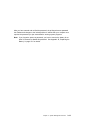
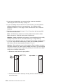
Using the 4.0GB 4-mm Tape Drive
The optional 4.0GB 4-mm tape drive is a half-high device.
Status Lights
The 4.0GB 4-mm tape drive has two green status lights and one amber status light.
The on and off combinations of the status lights indicate the conditions of the 4-mm
tape drive.
Each of the International Organization for Standards (ISO) symbols located over a
status light indicates a specific condition of the tape drive as follows:
Chapter 2. Using the System Unit
2-37
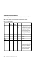
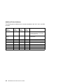
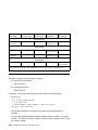
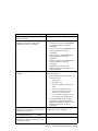
Status Light States
The following tables explain the meaning of the green and amber status lights.
Ready (green)
Read-Write (green)
Disturbance (amber)
Off
No cartridge installed or
error condition
No cartridge or no activity
No error condition
Steady
Cartridge installed or
loading/unloading
Flashing
Power-on self- test in
progress
Cleaning required or worn
media
Cartridge activity
Error condition
Status Lights on the 4.0GB 4-mm Tape Drive
Status
Ready
(green)
Read-Write
(green)
Disturbance
(amber)
LED test.
On 2
seconds at
power on
On 2
seconds at
power on
On 2
seconds at
power on
The power-on self-test (POST) is running or the
Diagnostic Cartridge is running.
Flashing
Off
Off
One of the following has occurred:
Off
Off
Off or On
A tape cartridge has been inserted and the 4-mm
Tape Drive is Ready to receive commands from
the system.
On
Off
Off or ON
The tape is in motion and the 4-mm Tape Drive is
running a device operation or cleaning.
On
Flashing
Off or On
The 4-mm Tape Drive has detected an internal
error that requires corrective action such as tape
cartridge failure, high humidity, or no SCSI
terminator. Refer to the service guide or contact
your service representative. (See note below)
Off
Off
Flashing
The tape path requires cleaning or a poor quality
tape cartridge is being used. See “Cleaning the
Tape Path on the 4.0GB 4-mm Tape Drive” on
page 2-41.
Off or On
Off or
Flashing
On
The power is off.
The POST has completed successfully, but
no tape cartridge has been loaded.
Note: If an error condition occurs, first try to recover by pressing the unload button.
If this does not correct the error, switch off the power to the 4-mm tape drive and
then switch on the power to the drive. If the condition continues, call your service
representative.
2-38
IBM RS/6000 7025 F50 Series User's Guide
Loading the 4-mm Tape Cartridge
Before loading the tape cartridge, make sure the power is on and the write-protect
switch on the tape cartridge is properly set. Refer to “Setting the Write-Protect Tab
on 4-mm Tape Cartridges” on page 2-34. The tape drive loads the tape from the
cartridge and prepares it for reading and writing.
To load the 4-mm tape cartridge, do the following:
1. Grasp the edges of the 4-mm tape cartridge with the write-protect tab towards
you and the window side of the cartridge facing up.
2. Slide the tape cartridge into the opening on the front of the 4-mm tape drive until
the loading mechanism pulls the cartridge into the drive and the drive door
closes. The ready status light (green) goes on if the load operation was
successful.
The 4-mm tape drive is ready for data operations when the tape cartridge is inserted.
After the cartridge is inserted into the tape drive, the tape takes about 15 seconds to
load.
Chapter 2. Using the System Unit
2-39
Unloading the 4-mm Tape Cartridge
Before performing the unload operation, make sure the power to the 4-mm tape drive
is on.
To unload and eject the tape cartridge, press the unload button. The 4-mm tape
drive rewinds the tape and then ejects the tape cartridge from the tape drive.
After pressing the unload button, the following occurs:
1. The Read-Write status light flashes during the unload operation.
2. The Ready status light and the Read-Write status light turns off when the
cartridge is ejected from the tape drive.
The time required for a tape to rewind and unload is between 10 seconds and 1.5
minutes, depending on the position of the tape when the unload button is pushed.
If the tape cartridge cannot unload and has to be removed manually from the drive,
contact your service representative.
2-40
IBM RS/6000 7025 F50 Series User's Guide
Cleaning the Tape Path on the 4.0GB 4-mm Tape Drive
The 4-mm tape path should be cleaned either approximately every 30 hours of tape
motion or once a month, whichever occurs first. The 4-mm tape drive monitors the
recording quality of the tape cartridge and indicates that the tape path requires
cleaning when the disturbance status light (amber) is on.
More frequent cleaning may be required if the drive is operated in a dusty
environment or in humid conditions. If the dust is allowed to accumulate, the drive
has to perform more reads and writes. This can cause data loss, and may be
prevented by regularly scheduled cleaning of the drive.
The cleaning cartridge cleans the 4-mm tape drive 50 times before it needs to be
discarded. If you attempt to use a 4-mm cleaning cartridge more than 50 times, the
tape drive automatically detects the error and ejects the cleaning cartridge with the
disturbance status light (amber) remaining on.
Before loading the cleaning cartridge, make sure the power to the 4-mm tape drive is
on.
To load the 4-mm cleaning cartridge, do the following:
1. Grasp the edges of the 4-mm cleaning cartridge with the window side of the
cartridge facing up.
2. Slide the cleaning cartridge into the opening on the front of the 4-mm tape drive
until the loading mechanism pulls the cartridge into the drive.
After the 4-mm cleaning cartridge has been fully inserted into the 4-mm tape drive,
the following cleaning operations are performed automatically:
1. The cleaning tape is loaded into the tape path.
Chapter 2. Using the System Unit
2-41
2. The drive is cleaned by moving the cleaning tape forward for approximately 30
seconds.
3. The tape is unloaded and the cleaning cartridge is ejected from the tape drive
when the cleaning operation is complete.
4. A successful cleaning operation is indicated when the disturbance status light
(amber) goes off (if it was activated before the cleaning operation).
If the cleaning cartridge has been used more than 50 times the disturbance status
light (Amber) will flash.
2-42
IBM RS/6000 7025 F50 Series User's Guide
Chapter 3. System Management Services
The System Management Services make it possible for you to view information
about your computer and to perform such tasks as setting passwords and changing
device configurations.
If you have chosen a graphical display as your system console, you can use the
graphical System Management Services described below. If you are using an ASCII
display as your system console, see “Text-Based System Management Services” on
page 3-24.
Graphical System Management Services
To start the Open Firmware command line or graphical System Management
Services, turn on or restart the computer.
After the logo is displayed, initialization icons appear across the bottom of the
screen.
To enter the Open Firmware command line, you must press the F8 key after the
keyboard icon appears during startup.
If you have pressed the F8 key, the Open Firmware command line (an "OK" prompt)
appears after the initialization and power-on self test (POST) are complete.
The Open Firmware command line is used to set up adapters that are not
configurable with the System Management Services. Your adapter documentation
directs you to use this option if it is needed.
To exit from the Open Firmware command enter reset-all or power the system
down and reboot.
Chapter 3. System Management Services
3-1
To enter the graphical System Management Services instead of the Open Firmware
command line, you must press the F1 key after the keyboard icon appears during
startup.
After the System Management Services starts, the following screen appears.
You may also press F8 here to enter the OK> prompt.
3-2
IBM RS/6000 7025 F50 Series User's Guide
The System Management Services screen contains the following choices.
Config: Enables you to view your system configuration.
MultiBoot: Invokes the Mulitboot menu which provides several
functions:
To Select a particular operating system to boot.
In the case of AIX this is a supported option, if you receive
a an informational icon after making this selection this
would mean that information in non-volatile storage could
have been lost, as would happen if the battery had been
removed. In order to recreate this value, issue the bootlist
command under AIX with the appropriate parameters as to
the location of the operating system in a particular hard
disk. Please see the explanation of the bootlist command
in your AIX documentation.
To select a particular operating system as the default
operating system
To install from the list of possible devices
To set the sequence in which devices are searched for
operating system startup code
To go to the Open Firmware command prompt
To set the Multiboot menu so that it comes up immediately
as the system powers up
Utilities: Enables you to set and remove passwords, enable
the unattended start mode, set and view the addresses of your
system's SCSI controllers, select the active console, view or
clear the error log, and update your system firmware.
Exit: Returns you to the previous screen.
Chapter 3. System Management Services
3-3
To select an icon, move the cursor with the arrow keys to choose which icon is
highlighted, then press the Enter key. You can also select an icon by clicking on it
with your left mouse button. To leave the current screen, either press the Esc key or
select the Exit icon.
3-4
IBM RS/6000 7025 F50 Series User's Guide
Config
Selecting this icon makes it possible for you to view information about the setup of
your system unit. A list similar to the following appears when you select the Config
icon.
Chapter 3. System Management Services
3-5
Selecting the down arrow key or Page Down key displays the next configuration
screen, which lists your computer's firmware version, the date of its development,
and the firmware part number.
The following screen is provided by the service processor.
3-6
IBM RS/6000 7025 F50 Series User's Guide
MultiBoot:
This selection invokes the Mulitboot menu which provides several functions:
To Select a particular operating system to boot.
In the case of AIX this is a supported option, if you receive a an informational
icon after making this selection this would mean that information in non-volatile
storage could have been lost, as would happen if the battery had been removed.
In order to recreate this value, issue the bootlist command under AIX with the
appropriate parameters as to the location of the operating system in a particular
hard disk. Please see the explanation of the bootlist command in your AIX
documentation.
To select a particular operating system as the default operating system
To install from the list of possible devices
To set the sequence in which devices are searched for operating system startup
code
To go to the Open Firmware command prompt
To set the Multiboot menu so that it comes up immediately as the system powers
up
The Select Software option, if supported by the operating system, shows the names
of the operating system installed. This option may not be supported by all operating
systems.
In the case of AIX this is a supported option, if you receive a message saying that:
No Operating System Installed
Chapter 3. System Management Services
3-7
this would mean that information in non-volatile storage could have been lost, as
would happen if the battery had been removed. In order to recreate this value issue
the bootlist command under AIX with the appropriate parameters as to the location of
the operating system in a particular Hard disk. Please see the explanation of the
bootlist command in your AIX documentation.
The Software Default option, if supported by the operating system, lets you select the
default operating system to start the system. This option may not be supported by
all operating systems.
The Install From option produces a list of devices, for example the CD-ROM, where
the operating system is installed from. You select one of the devices and the system
searches the device for an operating system to install and if supported by the
operating system in that device, the name of the operating system displays.
The Select Boot Device option provides a list of devices that can be selected to be
stored on the boot list. Up to 5 devices are supported.
The OK Prompt procvides access to the Open Firmware command prompt. The
Open Firmware command prompt is used for debug purposes, and device driver
development. Information about the commands that are available in the IEEE
Standard 1275.
The Multiboot Start option toggles between OFF and ON and selects if the Multiboot
menu invokes automatically on startup or not.
Boot
This selection enables you to view and change the custom boot list (the sequence in
which devices are searched for operating system startup code).
3-8
IBM RS/6000 7025 F50 Series User's Guide
Attention: If you change your startup sequence, you must be extremely careful
when performing write operations (for example, copying, saving, or formatting). You
can accidentally overwrite data or programs if you select the wrong drive.
The default boot sequence is:
The primary diskette drive
CD-ROM drive
Tape id=5 (slot=1)
Hard disk drive id=6 (Slot=1)
Network device.
To change the custom boot list, enter a new order in the New column, then select
Save. The List of Boot Devices is updated to reflect the order you have chosen.
You can choose 1 to 5 devices for the custom boot list. To change the boot
sequence back to the default values, select Default. (The default sequence is
automatically saved.)
Chapter 3. System Management Services
3-9
Utilities
Selecting this icon enables you to perform various tasks and view additional
information about your computer.
The following describes the choices available on this screen.
Password: Enables you to set password protection for turning
on the computer and for using system administration tools.
Error Log: Enables you to view and clear error log information
for your computer.
RIPL (Remote Initial Program Load): Allows you to select a
remote system from which to load programs via a network
adapter when your system unit is first turned on. This option
also allows you to configure network adapters which require
setup.
3-10
IBM RS/6000 7025 F50 Series User's Guide
Update: Allows you to update the firmware programs on your
computer.
Console: If you have more than one display attached to your
system unit, or if you have an ASCII terminal attached to your
system unit in addition to a keyboard and display, this tool
allows you to define which one is active.
Chapter 3. System Management Services
3-11
Password
When you select this icon, the following screen is displayed.
Power-On Password: Setting a power-on password helps protect information stored
in your computer. If a power-on password is set for your computer, the Power On
icon is shown in the locked position; if a power-on password is not set, then the
Power On icon is shown in the unlocked position (as in the screen above).
When you select the Entry icon, a screen with 8 empty boxes appears. Type your
password in these boxes. You can use any combination of up to eight characters
(A–Z, a–z, and 0–9) for your password. As you type a character, a key appears in
the box.
3-12
IBM RS/6000 7025 F50 Series User's Guide
Press Enter when you are finished; you are required to type the password again for
verification.
If you make a mistake, press the Esc key and start again.
After you have entered and verified the password, the power-on password icon
flashes and changes to the locked position to indicate that the power-on password is
set.
If you previously had set a power-on password and want to remove it, select the
Remove icon.
Note: If you forget the power-on password, you have to remove the battery for at
least 30 seconds to disable this password. See Appendix B, “Replacing the
Battery” on page B-1 for details.
Attention: After you remove the battery, you must reconfigure your system (bootlist,
IP parameters, console information, support processor, etc).
A password can be set only after the system is turned off and on again.
Chapter 3. System Management Services
3-13
Remote Mode: The remote mode, when enabled, allows the system to start from
the defined boot device. This mode is ideal for network servers and other computers
that operate unattended. You must set a power-on password before you can enable
the remote mode. When the remote mode is set, the icon changes to Remote
<On>.
If you remove the power-on password, the remote mode is automatically reset, and
the icon returns to Remote <Off>.
Privileged-Access Password: The privileged-access password protects against the
unauthorized starting of the system programs.
When you select the Entry icon, a screen with 8 empty boxes appears. Type your
password in these boxes. You can use any combination of up to eight characters
(A–Z, a–z, and 0–9) for your password. As you type a character, a key appears in
the box.
Press Enter when you are finished; you are required to type the password again for
verification.
If you make a mistake, press the Esc key and start again.
3-14
IBM RS/6000 7025 F50 Series User's Guide
After you have entered and verified the password, the privileged-access password
icon flashes and changes to the locked position to indicate that your computer now
requires the password you just entered before running system programs.
Note: If you forget the power-on password, you have to remove the battery for at
least 30 seconds to disable this password. See Appendix B, “Replacing the
Battery” on page B-1 for details.
Chapter 3. System Management Services
3-15
Error Log
Selecting this icon displays the log of errors your computer has encountered during
operations.
Selecting the Clear icon erases the entries in this log.
3-16
IBM RS/6000 7025 F50 Series User's Guide
RIPL
Selecting the Remote Initial Program Load (RIPL) icon above gives you access to
the following selections.
Chapter 3. System Management Services
3-17
The Set Address icon allows you to define addresses from which your computer can
receive RIPL code.
Notes:
1. Some applications may require that IP addresses contain leading zeroes for
numbers less than 100. For example, 129.132.4.20 may need to be entered as
123.132.004.020.
If any of the addresses is incomplete or contains a number other than 0 to 255, an
error message is displayed when you select the Save icon. To clear this error,
change the improper address and select Save again.
Note: You should save a copy of your changes in case you need to replace your
battery.
3-18
IBM RS/6000 7025 F50 Series User's Guide
The Ping icon allows you to confirm that a specified address is valid by sending a
test transmission to that address.
After choosing the Ping option, you may be asked to indicate which communications
adapter (Token Ring or Ethernet) should be used to send the test transmission.
Chapter 3. System Management Services
3-19
The Config icon allows you to configure network adapters which require setup.
Selecting the Config icon presents a list of the adapters requiring configuration. Use
the arrow keys to highlight an adapter, press the spacebar to select the adapter, then
highlight the OK icon and press the Enter key.
The next screen allows you to select the configuration of the adapter you have just
chosen (or allow the system to select the configuration automatically). As on the
previous screen, use the arrow keys to highlight, press the space bar to select, then
highlight the OK icon and press enter.
3-20
IBM RS/6000 7025 F50 Series User's Guide
SCSI ID
This selection allows you to view and change the addresses (IDs) of the SCSI
controllers attached to your system unit. To change an ID, highlight the entry by
moving the arrow keys, then use the space bar to scroll through the available ID's.
After you have entered the new address, use the arrow keys to highlight the Save
icon and press the Enter key.
At any time in this process, you can select the Default icon to change the SCSI IDs
to the default values.
Chapter 3. System Management Services
3-21
Update
This selection allows you to update the service processor and system firmware in
your system unit from an image on a 3.5 inch diskette. After choosing to update the
firmware and confirming this choice, you must insert the diskette containing the
firmware image.
ATTENTION: While the new firmware image is being copied into your system unit,
you must not turn off the system unit. Turning off the system unit during the
update process may render your system unit inoperable.
After the flash update is complete, the system unit restarts.
If the flash update does not complete successfully or the system unit does not restart
after the flash update, contact your authorized reseller or marketing representative.
3-22
IBM RS/6000 7025 F50 Series User's Guide
Firmware Recovery
If a troubleshooting procedure has indicated that the firmware information in your
system unit has been corrupted, then you must perform a firmware recovery.
To perform a firmware recovery, do the following:
1. Locate your firmware update diskette.
2. Using another system unit, rename the
*.img ,br file on the firmware update diskette to
precover.img
3. Make sure your system unit is turned off.
4. Insert the firmware recovery diskette into your system unit.
5. Turn on your system unit.
6. When the keyboard indicator appears, press the 1 key if the system console is
an ASCII terminal, or the F1 key if the system console is a directly-attached
keyboard.
7. When the System Management Services appear, choose Utilities and perform a
Firmware Update as described above.
Chapter 3. System Management Services
3-23
Text-Based System Management Services
The text-based Open Firmware command line and System Management Services are
available if an ASCII terminal is attached to your system unit. The text-based Open
Firmware command line allows you to configure some adapters, and the System
Management Services makes it possible for you to view information about your
system unit and to perform such tasks as setting passwords and changing device
configurations.
To enter the Open Firmware command line, you must press the 8 key after the
keyboard text symbol appears during startup.
If you have pressed the 8 key, the Open Firmware command line (an "OK" prompt)
appears after the initialization and power-on self tests (POST) are complete.
The Open Firmware command line can be used to set up adapters that are not
configurable with the System Management Services. Your adapter documentation
directs you to use this option if it is needed.
To exit from the Open Firmware command enter reset-all or power the system
down and reboot.
To start the text-based System Management Services instead of the Open Firmware
command line, press 1 on the ASCII terminal keyboard when the keyboard text
symbol appears during startup.
3-24
IBM RS/6000 7025 F50 Series User's Guide
After the text-based System Management Services starts, the following screen
appears.
à
ð
System Management Services
1.
2.
3.
4.
Display Configuration
Multiboot
Utilities
Select Language
.------.
|X=Exit|
------'
====>
á
ñ
Selecting the numbered options provide capabilities described on the following
pages.
After you have finished using the text-based System Management Services, entering
x (for exit) boots your computer.
Chapter 3. System Management Services
3-25
Display Configuration
This option provides information about the setup of your computer. A screen similar
to the following is displayed.
à
ð
Device
PowerPC 6ð4
L2-Cache, ð512K
Memory
slotA=8MB
slotB=8MB
LPT
addr=3BC
COM
addr=3F8
COM
addr=2F8
Audio
Keyboard
Mouse
Diskette
addr=3Fð
Integrated Ethernet
addr=8ððð5AF67BD
SCSI cntlr id=7
PCI Adapters
.-----------. .-----------.
|P=prev-page| |N=next-page|
-----------' -----------'
á
.------.
|x=Exit|
------'
ñ
Note that this configuration information does not include ISA adapters installed in the
system unit.
3-26
IBM RS/6000 7025 F50 Series User's Guide
MultiBoot Menu
à Multiboot Menu
1.
2.
3.
4.
5.
6.
ð
Select Software
Software Default
Install From
Select Boot Devices
OK Prompt
Mulitboot Startup <OFF> (or <ON>)
.------.
|X=Exit|
------'
===>
á
ñ
The Select Software option, if supported by the operating system, shows the names
of the operating system installed. This option may not be supported by all operating
systems.
In the case of AIX this is a supported option, if you receive a message saying that:
No Operating System Installed
this would mean that information in non-volatile storage could have been lost, as
would happen if the battery had been removed. In order to recreate this value issue
the bootlist command under AIX with the appropriate parameters as to the location of
the operating system in a particular Hard disk. Please see the explanation of the
bootlist command in your AIX documentation.
The Software Default option, if supported by the operating system, lets you select the
default operating system to start the system. This option may not be supported by
all operating systems.
The Install From option produces a list of devices, for example the CD-ROM, where
the operating system is installed from. You select one of the devices and the system
searches the device for an operating system to install and if supported by the
operating system in that device, the name of the operating system displays.
The Select Boot Device option provides a list of devices that can be selected to be
stored on the boot list. Up to 5 devices are supported.
Chapter 3. System Management Services
3-27
The OK Prompt procvides access to the Open Firmware command prompt. The
Open Firmware command prompt is used for debug purposes, and device driver
development. Information about the commands that are available in the IEEE
Standard 1275.
The Multiboot Start option toggles between OFF and ON and selects if the Multiboot
menu invokes automatically on startup or not.
Select Boot Devices
This selection enables you to view and change the custom boot list, which is the
sequence of devices read at startup time.
à Select Boot Devices
1.
2.
3.
4.
5.
6.
7.
ð
Display Current Settings
Restore Default Settings
Configure 1st Boot Device
Configure 2nd Boot Device
Configure 3rd Boot Device
Configure 4th Boot Device
Configure 5th Boot Device
.------.
|X=Exit|
------'
====>
á
ñ
Selecting the Display Current Settings option lists the current order of devices in the
boot list. The following screen shows an example of this display.
3-28
IBM RS/6000 7025 F50 Series User's Guide
à Current Boot Sequence
1.
2.
3.
4.
5.
Diskette
Ethernet (Integrated)
SCSI CD-ROM
SCSI 5ððMB Hard Disk
SCSI 5ððMB Hard Disk
ð
id=3
id=6
id=5
(slot=1)
(slot=1)
(slot=5)
.------.
|X=Exit|
------'
===>
á
ñ
Chapter 3. System Management Services
3-29
Selecting any of the Configure Boot Device options displays the following screen.
à
ð
Configure Nth Boot Device
Device Number
Current Position
1
2
3
4
5
1
2
3
4
-
.-----------. .-----------.
|P=prev-page| |N=next-page|
-----------' -----------'
Device Name
Diskette
Ethernet
SCSI CD-ROM
SCSI 4.5GB Hard Disk
.------.
|X=Exit|
------'
===>
á
3-30
ñ
IBM RS/6000 7025 F50 Series User's Guide
Utilities
The Utilities screen enables you to select from the following system management
tools.
à
ð
Utilities
1.
2.
3.
4.
5.
6.
7.
8.
Set Password and Unattended Start Mode
Audio <ON>
Display Error Log
Remote Initial Program Load Setup
Change SCSI id
Update System Firmware
Update Service Processor
Select Console
.------.
|X=Exit|
------'
===>
á
ñ
Set Password and Unattended Start Mode: Entering this selection permits
access to the following options.
à
ð
Password Utilities
1.
2.
3.
4.
5.
Set Power On Password
Remove Power On Password
Unattended Start Mode <OFF>
Set Privileged-Access Password
Remove Privileged-Access Password
.------.
|X=Exit|
------'
===>
á
ñ
Chapter 3. System Management Services
3-31
Set Power On Password: Setting a power-on password helps protect information
stored in your computer. You can use any combination of up to eight characters
(A–Z, a–z, and 0–9) for your password. The password you type is not displayed on
the screen. Press Enter when you are finished; you are required to type the
password again for verification.
If you previously had set a power-on password and wanted to remove it, select
Remove Power-On Password.
Note: If you forget your password, you have to shut down the computer and
remove the battery for at least 30 seconds to disable the password. See
Appendix B, “Replacing the Battery” on page B-1 for details.
A password can be set only after the system is turned off and on again.
3-32
IBM RS/6000 7025 F50 Series User's Guide
Set Privileged-Access Password: The privileged-access password protects against
the unauthorized starting of the system programs.
If you previously had set a privileged-access password and want to remove it, select
Remove Privileged-Access Password.
Note: If you forget your password, you have to shut down the computer and
remove the battery for at least 30 seconds to disable the password. See
Appendix B, “Replacing the Battery” on page B-1 for details.
Audio: Selecting this utility turns on or off the system tones heard at power-on
time.
Remote Initial Program Load Setup: This option allows you to enable and set
up the remote startup capability of your computer. First, you are asked to specify the
network parameters.
à
ð
Network Parameters
1. IP Parameters
2. Adapter Parameters
3. Ping
.------.
|X=Exit|
------'
===>
á
ñ
Note: Some applications may require that IP addresses contain leading zeroes for
numbers less than 100. For example, 129.132.4.20 may need to be entered as
123.132.004.020.
Chapter 3. System Management Services
3-33
Selecting the IP Parameters option displays the following screen.
à IP Parameters
1.
2.
3.
4.
Client IP Address
Server IP Address
Gateway IP Address
Subnet Mask
ð
ððð.ððð.ððð.ððð
ððð.ððð.ððð.ððð
ððð.ððð.ððð.ððð
ððð.ððð.ððð.ððð
.------.
|X=Exit|
------'
===>
á
ñ
Selecting the Adapter Parameters option allows you to view an adapter's hardware
address as well as configure network adapters that require setup.
à
ð
Adapter Parameters
Device
1. 3Com,3C9ð5
2. Token-Ring
HW Address
8ððð5AFC67BD
8ððð32E54A12
.------.
|X=Exit|
------'
á
3-34
ñ
IBM RS/6000 7025 F50 Series User's Guide
Selecting option 1 (3Com,3C905) displays the following 100Mb Ethernet
configuration menus:
à
ð
3Com Etherlink Fast XL
1. Media Type
2. Full Duplex
[Auto]
[Auto]
.------.
|X=Exit|
------'
á
ñ
Selecting the Media Type option allows you the change the media employed by the
Ethernet adapter:
à
ð
.----------------.
| MEDIA TYPE
|
| 1. 1ð BaseT
|
| 2. 1ðð Base TX |
| 3. Auto
|
----------------'
á
ñ
Chapter 3. System Management Services
3-35
Selecting the Full Duplex option allows you to change how the Ethernet adapter
communicates with the network:
à
ð
.----------------.
| Full Duplex
|
| 1. Yes
|
| 2. No
|
| 3. Auto
|
----------------'
á
ñ
Ping, the last option available from the Network Parameters menu, allows you to test
a connection to a remote system unit. After selecting the Ping option, you must
choose which adapter communicates with the remote system.
à
ð
Interface
1. Ethernet (Integrated)
2. Token Ring (Slot=3)
===>
á
3-36
ñ
IBM RS/6000 7025 F50 Series User's Guide
After choosing which adapter to use to ping the remote system, you must provide the
addresses needed to communicate with the remote system.
à Ping
1.
2.
3.
4.
ð
Client IP Address
Server IP Address
Gateway IP Address
Subnet Mask
.---------.
|E=Execute|
---------'
129.132.4.2ð
129.132.4.1ð
129.132.4.3ð
255.255.255.ð
.------.
|X=Exit|
------'
===>
á
ñ
Display Error Log: A screen similar to the following is displayed when you select
this option. Here, you can view or clear your computer's error log.
à
ð
.----------------------------------------------------------.
|
Error Log
|
|
|
|
Date
Time
ErrorCode
Location |
| Entry 1. 96/ð4/ð1
12:13:22
25A8ðð11
ðð-ðð
|
| Entry 2. no error logged
|
----------------------------------------------------------'
.-----------------.
|C=Clear Error Log|
-----------------'
á
.------.
|X=Exit|
------'
ñ
Change SCSI ID: This option allows you to view and change the addresses of the
SCSI controllers attached to you computer.
Chapter 3. System Management Services
3-37
Update System Firmware: This option allows you to update your system
firmware. Note that you must insert a diskette containing the firmware update image
after you see the following confirmation screen.
à
ð
.--------------------------------------------------------------.
| This selection will update your System Firmware. Do you want |
| to continue? Press Y(Yes) N(No).
|
--------------------------------------------------------------'
á
ñ
Firmware Recovery: If a troubleshooting procedure has indicated that the firmware
information in your system unit has been corrupted, then you must perform a
firmware recovery.
To perform a firmware recovery, do the following:
1. Locate your firmware update diskette.
2. Using another system unit, rename the
*.img
file on the firmware update diskette to
precover.img
3. Make sure your system unit is turned off.
4. Insert the firmware recovery diskette into your system unit.
5. Turn on your system unit.
6. When the keyboard indicator appears, press the 1 key on the system console
ASCII terminal.
7. When the System Management Services appear, choose Utilities and perform a
System Firmware Update as described above.
Select Console: Selecting this option allows you to define which display is used
by the system for system management.
3-38
IBM RS/6000 7025 F50 Series User's Guide
Select Language
This option allows you to change the language used by the text-based System
Management Services screens.
à
ð
SELECT LANGUAGE
1.
2.
3.
4.
5.
6.
====>
English
Francais
Deutsch
Italiano
Espanol
Svenska
á
.------.
|x=Exit|
------'
ñ
Note: Your ASCII terminal must support the ISO-8859 character set in order to
properly display languages other than English.
Chapter 3. System Management Services
3-39
3-40
IBM RS/6000 7025 F50 Series User's Guide
Chapter 4. Service Processor Menus
The Service Processor menus enable you to configure Service Processor options
and to enamle and disable functions.
Service Processor menus are available using an ASCII terminal when the server is
powered off and the Service Processor is operating with standby power. Service
Processor menus are also available when server power is on and the Service
Processor has detected a server problem (such as loss of surveillance).
During the first power up (i.e. power cord is plugged into the outlet), Service
Processor menus are not available for 45 seconds while the Service Processor is
running self-tests and initializing the server. If the server powers down, Service
Processor menus become available after 15 seconds.
For a summary of the Service Processor functions and the methods for invoking
them, see the table on page 4-2.
Chapter 4. Service Processor Menus
4-1
Service Processor Functions
2
3
Service
Processor
Service
Aids
(ASCII or
graphics
terminals)
Read VPD
Y3
View System Environmental Conditions
Y3
Read System POST Errors
Y3
Read Service Processor Error Logs
Y3
View Progress Indicators from last Boot
Y3
Power-on System
Y3
Power-off System
Y2
Read NVRAM
Y2
Reset Service Processor
Y2
Setup Reboot/Restart Policy
Y2
Start Talk Mode
Y2
Enable/Disable Console Mirroring
Y2
Y1
Select Modem Line Speed
Y
2
Y1
Enable/Disable Modem
Y2
Y1
Setup Modem Configuration
Y2
Y1
Setup Ring Indicate Power-On
Y
2
Y1
Setup Dial-out Phone Numbers
Y2
Y1
Setup Surveillance
Y2
Y1
2
Y1
SMS
(ASCII or
graphics
terminals)
Y3
Y2
Update Service Processor Flash EPROM
Y
Change General Access Password
Y2
Y2
Change Privileged Access Password
Y2
Y2
Select Language
Y2
Y2
2
Y2
Enable/Disable Unattended Start Mode
1
Service
Processor
Menus
(ASCII
terminals)
Operating system root password
Privileged access password
General access (power-on) password
4-2
IBM RS/6000 7025 F50 Series User's Guide
Y
Service Processor Menus
The Service Processor menus are divided into two groups:
General user menus - the user must know the general access password.
Privileged user menus - the user must know the privileged access password.
The following section describes these two groups of menus, how to access them,
and the functions associated with each option.
When the server is powered down, the Service Processor menus may be accessed
locally or remotely.
Menu Inactivity
To prevent loss of control in unstable power environments, the Service Processor
leaves the menu mode after 5 minutes of inactivity. Menus may be resumed by
pressing any key on the terminal, local or remote.
How to access Service Processor menus locally
Service Processor menus may be accessed locally by connecting an ASCII terminal
to either serial port. Because the presence of the ASCII terminal cannot be
confirmed by the Service Processor, you must press a key on the ASCII terminal to
confirm its presence. Next the Service Processor prompts you for a password (if
set), and when verified, displays the Service Processor menus.
How to access Service Processor menus remotely
Service Processor menus may be accessed remotely by connecting a modem to
serial port 1 or serial port 2.
Power off the server, unplug the power cord, and press the power button to drain
capacitance while power is disconnected.
Connect the modem to the appropriate serial port and turn the modem on.
Plug in the server.
Note: If your modem has not been configured, go to “CALL-IN/CALL-OUT SETUP
MENU” on page 4-16.
With a terminal or terminal emulator, call the server's modem. The Service
Processor prompts you for a password (if set), and when verified, displays the
Service Processor menus.
Chapter 4. Service Processor Menus
4-3
General User Menus
The menu options presented to the General user are a subset of the options
available to the Privileged user. The user must know the General Access Password
in order to access these menus.
à
ð
GENERAL USER MENU
1. Power-On System
2. Read VPD
3. Read Progress Indicators from Last System Boot
4. Read Service Processor Error Logs
5. Read System POST Errors
6. View System Environmental Conditions
99. Exit from Menus
á
ñ
Power-On System
Allows the user to power-on the system.
Read VPD
Displays manufacturer vital product data, such as serial numbers, part numbers,
etc.
4-4
IBM RS/6000 7025 F50 Series User's Guide
Read Progress Indicators from Last System Boot
Displays the boot progress indicators (check points), up to a maximum of 100,
from the system boot prior to the one in progress now. This historical
information may be useful to help diagnose system faults.
The progress indicators are displayed in two sections. Above the dashed line
are the progress indicators from the boot that produced the current sessions.
Below the dashed line are progress indicators from the boot preceding the one
that produced the current sessions.
The progress indication codes are chronological from bottom to top. The dashed
line merely represents the point where the latest boot started.
Read Service Processor Error Logs
Displays the Service Processor error logs.
The time stamp in this error log is Coordinated Universal Time (CUT), a.k.a.
Greenwich Mean Time (GMT). AIX error logs have more information available
and are able to time stamp with local time. See 4-35 for an example of the error
log.
Read System POST Errors
Selecting this item lets you review the results of the POST (Power-On Self Test).
Your server may be able to start in the presence of POST errors if there is
sufficient working system resources. If POST errors occur during start-up, this
error log when used with the diagnostics helps to isolate faults. See 4-36 for an
example of the POST error screen.
View System Environmental Conditions
On selection of this menu, the Service Processor reads all environmental
sensors and reports the results to the user. This option maybe useful when
surveillance fails, as it allows the user to determine the environmental conditions
that may be related to the failure. See 4-14 for an example of the System
Environmental Conditions screen.
Chapter 4. Service Processor Menus
4-5
Privileged User Menus
The following menus are available to privileged users only. The user must know the
Privileged Access Password in order to access these menus.
MAIN MENU
At the top of the MAIN Menu is a listing containing:
Your Service Processor's current firmware version
The firmware copyright notice
The System Name given to your server during setup
You need the firmware version for reference when you either update or repair the
functions of your service processor.
The System Name, an optional field, is the name your server reports in problem
messages. This name helps your support team, (for example, your system
administrator, network administrator, or service representative) to more quickly
identify the location, configuration, and history of your server. The System Name is
set from the Main Menu using option 6.
4-6
IBM RS/6000 7025 F50 Series User's Guide
Note: The information under the Service Processor Firmware heading in the Main
Menu example that follows is example information only.
à
ð
Service Processor Firmware
EPROM: 1997ð915
FLASH: 1997ð512
Copyright 1997, IBM Corporation
SYSTEM NAME
MAIN MENU
1. Service Processor Setup Menu
2. System Power Control Menu
3. System Information Menu
4. Language Selection Menu
5. Call-In/Call-Out Setup Menu
6. Set System Name
99. Exit from Menus
á
ñ
Chapter 4. Service Processor Menus
4-7
Service Processor SETUP MENU
à
ð
Service Processor SETUP MENU
1. Change Privileged Access Password
2. Change General Access Password
3. Enable/Disable Console Mirroring:
Currently Disabled
4. Start Talk Mode
5. OS Surveillance Setup Menu
6. Reset Service Processor
7. Reprogram Service Processor Flash EPROM
98. Return to Previous Menu
99. Exit from Menus
á
ñ
Note
Unless otherwise stated in menu responses settings become effective when a
menu is exited using option 98 or 99.
4-8
IBM RS/6000 7025 F50 Series User's Guide
Passwords
Passwords can be any combination of up to 8 alphanumeric characters. You can
enter longer passwords, but the entries are truncated to include only the first 8
characters. Passwords can be set from the Service Processor menu or from the
SMS menus.
For security purposes, the Service Processor counts the number of attempts to enter
correct passwords. The results of not recognizing a correct password within this
error threshold are different, depending on whether the attempts are being made
locally (at the server) or remotely (via a modem). The error threshold is 3.
If the error threshold is reached by someone entering passwords at the server, the
Service Processor exits the menus. This action is taken based on the assumption
that the server is in an adequately secure location with only authorized users having
access. Such users must still successfully enter a login password to access AIX.
If the error threshold is reached by someone entering passwords remotely, the
Service Processor disconnects the modem to prevent potential security attacks on
the server by unauthorized remote users.
The following illustrates what you can access with the Privileged Access Password
and the General Access Password.
Privileged
Access
Password
General
Access
Password
Resulting Menu
None
None
MAIN MENU displayed
None
Set
MAIN MENU displayed
Set
None
User's with password see the MAIN MENU
Others users see the GENERAL USER MENU
Set
Set
Users see menus associated with the entered password
Change Privileged Access Password
Set or change the Privileged Access Password. It provides the user with the
capability to access all Service Processor functions. This password is usually
used by the system administrator or root user.
Change General Access Password
Set or change the General Access Password. It provides limited access to
Service Processor menus, and is usually available to all users who are allowed
to power-on the server.
Enable/Disable Console Mirroring
Chapter 4. Service Processor Menus
4-9
When Console Mirroring is enabled, the Service Processor sends information to
both serial ports. This capability may be enabled by local or remote users. This
provides local users the capability to monitor remote sessions. Console mirroring
may be enabled for the current session only. For more information, see “Console
Mirroring” on page 4-32.
Start Talk Mode
In a console mirroring session, it is useful for those that are monitoring the
session to be able to communicate with each other. Selecting this menu item
activates the keyboards and displays for such communications while console
mirroring is established. This is a full duplex link, so message interference is
possible. Alternating messages between users works best.
4-10
IBM RS/6000 7025 F50 Series User's Guide
Surveillance Setup Menu
This option may be used to setup operating system surveillance.
à
ð
OS Surveillance Setup Menu
1. Surveillance:
Currently Disabled
2. Surveillance Time Interval:
Currently 5
3. Surveillance Delay:
Currently 1ð
98. Return to Previous Menu
á
ñ
– Surveillance
May be set to Enabled or Disabled.
– Surveillance Time Interval:
May be set to any number from 2 to 255 minutes.
– Surveillance Delay:
May be set to any number from 0 to 255 minutes.
Refer to “Service Processor System Monitoring - Surveillance” on page 4-29 for
more information about surveillance.
Reset Service Processor - Allows the user to reinitialize the Service Processor.
Reprogram Service Processor Flash EPROM - This is an automatic process.
An update diskette can be acquired from the RS/6000 Support page on the
Internet or from your service team. The Internet address is:
http://www.rs6ððð.ibm.com/support/micro
The update files must be downloaded to a DOS-formatted diskette. You should
format the diskette just prior to receiving the download, to be sure it is clean.
Reformatting is worth the time and effort. When this process is selected, you are
prompted to place the diskette into the drive and to indicate to the system that
the diskette in available and the automatic process starts. If the system has other
needs, you are prompted. See “Service Processor Firmware Updates” on
page 4-33 for additional information and update methods.
Chapter 4. Service Processor Menus
4-11
SYSTEM POWER CONTROL MENU
à
ð
SYSTEM POWER CONTROL MENU
1. Enable/Disable Unattended Start Mode:
Currently Disabled
2. Ring Indicate Power-On Menu
3. Reboot/Restart Policy Setup Menu
4. Power-On System
5. Power-Off System
98. Return to Previous Menu
99. Exit from Menus
á
ñ
Enable/Disable Unattended Start Mode
This option may be used to instruct Service Processor to immediately power-on
the server after a power failure, bypassing power-on password verification.
Unattended Start Mode can also be set via SMS Menus. It is intended to be
used on servers that require automatic power-on after a power failure.
Ring Indicator Power-On Menu
Ring Indicate Power-On is an alternate method of dialing in, without establishing
a Service Processor session. If the system is powered off, Ring Indicate
Power-On is enabled, the server is powered on at the predetermined number of
rings, If the server is already on, no action is taken. In either case, the telephone
call is not answered. The caller receives no feedback that the server
powered-on. The Ring Indicator Power-On Menu and defaults are shown
below:
à
ð
Ring Indicator Power-On Menu
1. Ring Indicate Power-On :
Currently Disabled
2. Number of Rings :
Currently 6
98. Return to Previous Menu
á
4-12
ñ
IBM RS/6000 7025 F50 Series User's Guide
– Ring Indicate Power-On may be set to 'Enabled' or 'Disabled'.
– Number of Rings may be set to any number from 1 to 255.
Reboot/Restart Policy Setup Menu, see “Reboot/Restart Policy Setup Menu”
on page 4-23.
Power-on System
Lets you power-on the system immediately. For other power-on methods see
“System Power-On Methods” on page 4-26.
Power-off System
Allows the user to power-off the server following a surveillance failure.
SYSTEM INFORMATION MENU
à
ð
SYSTEM INFORMATION MENU
1. Read VPD
2. Read VPD Image from Last System Boot
3. Read Progress Indicators from Last System Boot
4. Read Service Processor Error Logs
5. Read System POST Errors
6. Read NVRAM
7. View System Environmental Conditions
98. Return to Previous Menu
99. Exit from Menus
á
ñ
Read VPD
Displays manufacturer's vital product data, such as serial numbers, part
numbers, etc.
Read VPD Image from Last System Boot
Displays the VPD information that was in effect after the last system boot. This
information will usually be identical with the results from the menu selection
"Read VPD," but in the case of configuration updates or certain faults, this
Chapter 4. Service Processor Menus
4-13
historical comparison can be useful to System Administrators and service
personnel.
Read Progress Indicators from Last System Boot
Displays the boot progress indicators (check points), up to a maximum of 100,
from the system boot prior to the one in progress now. This historical
information may be useful to help diagnose system faults.
The progress indicators are displayed in two sections. Above the dashed line
are the progress indicators from the boot that produced the current sessions.
Below the dashed line are progress indicators from the boot preceding the one
that produced the current sessions.
The progress indication codes are chronological from bottom to top. The dashed
line merely represents the point where the latest boot started.
Read Service Processor Error Logs
Displays error conditions detected by the Service Processor.
The time stamp in this error log is Coordinated Universal Time (CUT), a.k.a.
Greenwich Mean Time (GMT). AIX error logs have more information available
and are able to time stamp with local time. See 4-35 for an example of the error
log.
Read System POST Errors
Selecting this item lets you review the results of the POST (Power-On Self Test).
Your server may be able to start in the presence of POST errors if there is
sufficient working system resources. If POST errors occur during start-up, this
error log when used with the diagnostics helps to isolate faults. See 4-36 for an
example of the POST error screen.
Read NVRAM
Displays Non-Volatile Random Access Memory (NVRAM) content.
View System Environmental Conditions
The Service Processor reads all environmental sensors and reports the results to
the user. This option is most useful when surveillance fails, as it allows the user
to determine the environmental conditions that may be related to the failure.
The following is an example of system environment conditions:
4-14
IBM RS/6000 7025 F50 Series User's Guide
à
System Environmental Conditions
(System Power is currently off.)
ð
Fan ð: A stopped fan detected
Fan 1: A stopped fan detected
Fan 2: A stopped fan detected
Fan 3: A stopped fan detected
MEM Temperature is operating within normal tolerances
I/O Temperature is operating within normal tolerances
CPU Temperature is operating within normal tolerances
5.ð Volts: A low 5.ð Voltage reading detected
3.3 Volts: A low 3.3 Voltage reading detected
5.ð Standby Volts: is operating within normal tolerance
+12.ð Volts: A low +12.ð voltage reading detected
-12.ð Volts: A high -12.ð voltage reading detected
(Press Return to Continue)
á
ñ
LANGUAGE SELECTION MENU
à
ð
LANGUAGE SELECTION MENU
1. English
2. Francais
3. Deutsch
4. Italiano
5. Espanol
6. Svenska
98. Return to Previous Menu
99. Exit from Menus
á
ñ
Note: Your ASCII terminal must support the ISO-8859 character set in order to
properly display languages other than English.
This menu allows selecting languages into which Service Processor and system
firmware menus and messages are displayed.
Chapter 4. Service Processor Menus
4-15
CALL-IN/CALL-OUT SETUP MENU
à
ð
CALL-IN/CALL-OUT SETUP MENU
1. Modem Configuration Menu
2. Serial Port Selection Menu
3. Serial Port Speed Setup Menu
4. Telephone Number Setup Menu
5. Call-Out Policy Setup Menu
6. Customer Account Setup Menu
7. Call-Out Test
8. Ring Indicate Power-On Menu
98. Return to Previous Menu
99. Exit from Menus
á
ñ
Modem Configuration Menu, see “Modem Configuration Menu.”
Serial Port Selection Menu, see “Serial Port Selection Menu” on page 4-17.
Telephone Number Setup Menu, see “Telephone Number Setup Menu” on
page 4-18.
Call-Out Policy Setup Menu, see “Call-Out Policy Setup Menu” on page 4-20.
Customer Account Setup Menu, see “Customer Account Setup Menu” on
page 4-22.
Ring Indicate Power-On Menu, see on page 4-12.
Modem Configuration Menu
The first two lines of the Modem Configuration Menu are status lines showing the
current selections. Selections are made in the two section labeled Modem Ports and
Modem Configuration File Name. Select the serial port that you that you want to
activate and then select the modem configuration file for the modem on the port. If
you wish to set up both serial ports with modems, make your selections one port at a
time.
4-16
IBM RS/6000 7025 F50 Series User's Guide
For information on choosing a modem configuration file, see “Sample Modem
Configuration Files” on page D-1 and “Seamless Transfer of a Modem Session” on
page D-6.
à
ð
Modem Configuration Menu
Port 1 Modem Configuration File Name:
Port 2 Modem Configuration File Name:
To make changes, First select the port and then the configuration file
name
Modem Ports:
1. Serial port 1
2. Serial port 2
Modem
3.
4.
5.
6.
7.
8.
Configuration File Name:
modem_f_sp
modem_fð_sp
modem_f1_sp
modem_z_sp
modem_zð_sp
none
9. Save configuration to NVRAM and Configure modem
98. Return to Previous Menu
á
ñ
Serial Port Selection Menu
à
ð
Serial Port Selection Menu
1. Serial Port 1 Call-Out:
Currently Disabled
2. Serial Port 2 Call-Out:
Currently Disabled
3. Serial Port 1 Call-In:
Currently Disabled
4. Serial Port 2 Call-In:
Currently Disabled
98. Return to Previous Menu
á
ñ
Chapter 4. Service Processor Menus
4-17
You may enable and/or disable the call-in and call-out functions of each serial port in
any combination.
Serial Port Speed Setup Menu
à
ð
Serial Port Speed Setup Menu
1. Serial Port 1 Speed:
Currently 96ðð
2. Serial Port 2 Speed:
Currently 96ðð
98. Return to Previous Menu
á
ñ
Serial port speed can be set for terminal performance or to accommodate modem
capabilities. A speed of 9600 baud or higher is recommended. Valid serial port
speeds are shown below:
50
75
110
134
150
300
600
1200
1800
2000
2400
3600
4800
7200
9600
19200
38000
57600
115200
Telephone Number Setup Menu
This menu may be used to set or change the telephone numbers for reporting a
system failure. The Service Processor allows setting or changing telephone numbers
for:
Service Center Telephone Number: - The telephone number of the maintenance
provider's computer.
Customer Administration Center Telephone Number: - The telephone number of
the local system support provider's computer.
Digital Pager Telephone Number: The number for a pager carried by someone
who will respond to problem calls from your server.
Customer Voice Telephone Number: - The telephone number service personnel
will use to reach the system user.
Customer System Telephone Number: - The telephone number to which the
server's modem is connected.
4-18
IBM RS/6000 7025 F50 Series User's Guide
à
ð
Telephone Number Setup Menu
1. Service Center Telephone Number:
Currently Unassigned
2. Customer Administration Center Telephone Number:
Currently Unassigned
3. Digital Pager Telephone Number:
Currently Unassigned
4. Customer Voice Telephone Number:
Currently Unassigned
5. Customer System Telephone Number:
Currently Unassigned
98. Return to Previous Menu
á
ñ
Service Center Telephone Number is the number of the service center
computer. The service center usually includes a computer that takes calls from
servers with call-out capability. This computer is referred to as "the catcher."
The catcher expects messages in a specific format to which Service Processor
conforms. For more information about the format and catcher computers, refer
to the README file in the AIX /usr/samples/syscatch directory. Contact your
service provider for the correct telephone number to enter here. Until you have
that number, leave this field blank.
Customer Administration Center Telephone Number is the number of the
System Administration Center computer (catcher) that receives problem calls
from servers. Contact your system administrator for the correct telephone
number to enter here. Until you have that number, leave this field blank.
Digital Pager Telephone Number is the number for a pager carried by
someone who will respond to problem calls from your server. Contact your
administration center representative for the correct telephone number to enter
here. For test purposes, enter your telephone number here. You can change it
later when testing is complete.
Note:
Some modems, such as IBM 7857-017, are not designed for the paging
function. Although they can be used for paging, they will return an error
message when they do not get the expected response from another
modem. Therefore, even though the paging was successful, the error
message will cause the Service Processor to retry, continuing to place
pager calls for the number of retries specified in the Call-Out policy Setup
Menu. These retries result in redundant pages.
Chapter 4. Service Processor Menus
4-19
For digital pagers that require a personal Identification Number (PIN) for access,
include the PIN in this field as in the following example:
1 8ðð 123 4567,,,,87654
where the commas create pauses1 for the voice response system, and the
87654 represents the PIN.
Customer Voice Telephone Number is the telephone number of a phone near
the server or answered by someone responsible for the server. This is the
telephone number left on the pager for callback. For test purposes, enter your
telephone number here. You can change it after testing is completed.
Customer System Telephone Number is the telephone number to which your
server's modem is connected. The service or administration center
representatives need this number to make direct contact with your server for
problem investigation. This is also referred to as the call-in phone number.
Call-Out Policy Setup Menu
à
ð
CALL-OUT POLICY SETUP MENU
1. Call-Out policy (First/All):
Currently First
2. Remote timeout, (in seconds):
Currently 12ð
3. Remote latency, (in seconds):
Currently 2
4. Number of retries:
Currently 2
98. Return to Previous Menu
á
ñ
Call Out policy may be set to 'first' or 'all'. If call out policy is set to 'first', the
Service Processor will stop at the first successful call out to one of the following
numbers in the order listed:
1. Service Center
2. Customer Admin Center
3. Pager
1
The length of these pauses is set in modem register S8. The default is usually 1 or 2 seconds each.
4-20
IBM RS/6000 7025 F50 Series User's Guide
If call out policy is set to 'all', the Service Processor will attempt a call out to all
the following numbers in the order listed:
1. Service Center
2. Customer Admin Center
3. Pager
Remote timeout and Remote latency are functions of your service provider's
catcher computer. You should take the defaults or contact your service provider
for recommended settings.
Number of retries is the number of times you want the server to retry calls that
resulted in busy signals or other error messages.
Chapter 4. Service Processor Menus
4-21
Customer Account Setup Menu
à
ð
Customer Account Setup Menu
1. Customer Account Number:
Currently Unassigned
2. Customer RETAIN Login UserID:
Currently Unassigned
3. Customer RETAIN Login Password:
Currently Unassigned
98. Return to Previous Menu
á
ñ
Customer Account Number is assigned by your service provider for record
keeping and billing. If you have an account number, enter it here. Otherwise,
leave this field blank.
Customer RETAIN Login UserID and Customer RETAIN Login Password
apply to a service function to which your service provider may or may not have
access. Leave these fields blank if your service provider does not use RETAIN.
4-22
IBM RS/6000 7025 F50 Series User's Guide
Reboot/Restart Policy Setup Menu
Reboot describes bringing the system hardware back up from scratch, for example,
from a system reset or power on. The boot process ends when control passes to the
operating system process.
Restart describes activating the operating system after the system hardware
reinitialized. Restart must follow a successful reboot.
à
ð
Reboot/Restart Policy Setup Menu
1. Number of reboot attempts:
Currently 3
2. Use OS-Defined restart policy?
Currently Yes
3. Enable supplemental restart policy?
Currently No
4. Call-Out before restart:
Currently Disabled
98. Return to Previous Menu
á
ñ
Number of reboot attempts if the server fails to successfully complete the boot
process, it attempts to reboot the number of times specified. Entry values equal
to or greater than 0 are valid. Only successive failed reboots attempts count, not
reboots that occur after a restart attempt. At restart, the counter is set to 0.
Use OS-Defined restart policy lets the Service Processor react or not react the
same as the operating system to major system faults, by reading the setting of
the operating system parameter Automatically Restart/Reboot After a System
Crash. This parameter may, or may not be defined depending on the operating
system or its version/level. If the operating system automatic restart setting is
defined, then it may be set to respond to a major fault by restarting or by not
restarting. See your operating system documentation for details on setting up
operating systems automatic restarts. The default value is YES.
Enable supplemental restart policy - The default setting is NO. If set to YES,
the Service Processor restarts the system when the system loses control as
detected by the Service Processor surveillance, and either:
1. The Use OS-Defined restart policy is set to NO
OR
Chapter 4. Service Processor Menus
4-23
2. The Use OS-Defined restart policy is set to YES and the operating system
has NO automatic restart policy.
Refer to “Service Processor Reboot/Restart Recovery” on page 4-27.
Call-Out before restart (Enabled/Disabled) If a restart is necessary due to a
system fault, you can enable the Service Processor to call out and report the
event. This item is valuable if the number of these events becomes excessive,
signalling a bigger problem.
Service Processor Functions and Features
The following section discusses some of the Service Processor functions and
features more fully.
The IBM RS/6000 7025 F50 Series supports the following functions:
Built-in Functions
Initialization and Test
Service Processor Basic
Instructions Test (BIST)
JTAG System Chip
Initialization
Error Data Collection
BIST/POST errors and status
Checkstop FIR data logout
Machine check logout
Configuration
CPU Complex validation
VPD Collection
System Management
Reset and Reboot on System
Firmware fail
Reboot on system failure
4-24
IBM RS/6000 7025 F50 Series User's Guide
Local User Function
User Interface
Local async console
Text based menus with NLS
Operator Panel messages
Power and Miscellaneous
Power On/Off
Configurable Reboot Policy
Status and Data Access
VPD
Error data (Service Processor)
Error data (system)
Environmental data
Service Processor Setup
Utilities
Passwords
Phone numbers
Language (NLS) selection
Call In/Call Out enable/disable
Flash (Gold/Recovery block)
Update
Flash (Composite block)
Update
System Name
Modem Configuration
Remote User Functions
Call Out (Call Home)
Reporting
Boot failure
OS Termination
Surveillance failure
Critical EPOW reporting
Checkstop
Machine check
Indentify system by name
Call In
Power-on via ring-indicate
Password/security check
Console mirroring/Quick
disconnect
Application Interface Functions
Monitor/Sense
Thermal/Voltage/fan speed
SP Flash Update(Recovery
and Composite)
Chapter 4. Service Processor Menus
4-25
System Power-On Methods
Power-on Switch - see “Starting the System Unit” on page 2-1.
SP Menu power-on request
You can request a power-on via the Service Processor menus from either a local
or remote terminal.
If a remote terminal is to be used, the modem must be connected to serial port
1, and the operating system set up to enable a TTY login session on that port.
Refer to “Seamless Transfer of a Modem Session” on page D-6 for information
on transferring modem sessions from Service Processor to the operating system.
Unattended start mode - refer to Enable/Disable Unattended Start Mode on
page 4-12.
The Service Processor can be enabled to recover from the loss of AC power
(see Enable/Disable Unattended Power-On Mode in the SYSTEM POWER
CONTROL MENU). When AC power is restored, the system returns to the then
current power state at the time AC loss occurred. For example, if the system
was powered-on when AC loss occurred, it reboots/restarts when power is
restored. If the system was powered-off when AC loss occurred, it remains off
when power is restored.
Timed power-on - refer to the shutdown -t command on servers using AIX.
Working in conjunction with AIX, the Service Processor in your server can
operate a timer, much like the wake-up timer on your clock radio. You can set
the timer so that your server powers on at a certain time after shutting down.
The timer is battery operated, so power interruptions occurring while the server is
off do not affect its accuracy. Refer to the shutdown -t command of AIX for
details on setting the timer.
Because of the potential for AC power loss, the Timed Power-On function of AIX
can only be assured when Unattended Power-On Mode is enabled. If a Timed
Power-On event occurs during an AC power loss, and if Unattended Power-On
Mode is enabled, the system starts when AC power is restored.
If Unattended Start Mode is disabled (the default), the system power state
remains off when AC power is restored, regardless of the power state of the
system when AC loss occurred.
Ring Indicate Power-On
Enabling ring indicate power-on disables remote call-in. If ring indicate power-on
is enabled, the server will power on at a predetermined number of rings. If the
server is already on, no action is taken. In either case, the telephone call is not
answered. The caller receives no feedback that the server powered on.
4-26
IBM RS/6000 7025 F50 Series User's Guide
Follow-up to a Failed Boot Attempt
The Service Processor will initiate a power-on sequence upon detection of a
failed boot attempt.
Service Processor Reboot/Restart Recovery
Reboot describes bringing the system hardware back up from scratch, for example,
from a system reset or power on. The boot process ends when control passes to the
operating system process.
Restart describes activating the operating system after the system hardware
reinitialized. Restart must follow a successful reboot.
Failure During Boot Process: During the boot process, either initially after
system power-on or upon reboot after a system failure, the Service Processor (SP)
monitors the boot progress (via surveillance). If progress stops, the Service
Processor can reinitiate the boot process (reboot) if enabled to do so. The Service
Processor can re-attempt this process according to an entry on the Reboot/Restart
Policy Setup Menu.
Failure During Normal System Operation: When the boot process completes
and control transferers to the operating system (OS), the Service Processor can
monitor operating system activity (see the SERVICE PROCESSOR SETUP MENU
item Set Surveillance Parameters). If OS activity stops, the Service Processor can
initiate a reboot/restart process based on the settings in the Service Processor
Reboot/Restart Policy Setup Menu and the OS automatic restart settings (see OS
documentation).
If the operating system is AIX, the menu item under SMIT for setting the restart
policy is Automatically Reboot After Crash (True/False), and the default is False.
When the setting is True, and if the SP parameter, Use OS-Defined Restart Policy, is
Yes (the default), the Service Processor takes over for AIX to reboot/restart after a
Check Stop or Surveillance failure.
Service Processor Reboot/Restart Policy Controls: The operating system's
automatic restart policy (see operating system documentation) indicates the OS
response to a system crash. The SP can be instructed to refer to that policy, or not,
by the Use OS-Defined Restart Policy menu item.
If the operating system has no automatic restart policy, or if it is disabled, then the
Service Processor restart policy can be controlled from the Service Processor Menus
by using the Enable Supplemental Restart Policy selection.
Chapter 4. Service Processor Menus
4-27
Use OS-Defined restart policy?: The Use OS-Defined restart policy default
setting is YES. This causes the SP to refer to the OS Automatic Restart Policy
setting and take action, the same action the OS would take if it could have
responded to the problem causing the restart.
When this setting is NO, or if the OS did not set a policy, the Service Processor
refers to Enable supplemental restart policy for its action.
Enable Supplemental Restart Policy?: The default setting is NO. If set to
YES, the Service Processor restarts the system when the system loses control as
detected by the Service Processor surveillance, and either:
1. The Use OS-Defined restart policy is set to NO
OR
2. The Use OS-Defined restart policy is set to YES and the operating system has
NO automatic restart policy.
Refer to “Service Processor Reboot/Restart Recovery” on page 4-27.
The following provides a more thorough understanding of the relations among the
OS and Service Processor restart controls:
1
2
OS Automatic
reboot/restart
after crash setting
SP to use
OS-Defined
restart policy?
SP Enable
supplemental
restart policy?
None
None
None
None
False²
False²
False²
False²
True
True
True
True
No
No
Yes±
Yes±
No
No
Yes±
Yes±
No
No
Yes±
Yes±
No±
Yes
No±
Yes
No±
Yes
No±
Yes
No±
Yes
No±
Yes
Service Processor default
AIX default
4-28
IBM RS/6000 7025 F50 Series User's Guide
System response
Restarts
Restarts
Restarts
Restarts
Restarts
Restarts
Service Processor System Monitoring - Surveillance
Surveillance is a function in which the Service Processor monitors the system, and
the system monitors the Service Processor. This monitoring is accomplished by
periodic samplings called heartbeats.
Surveillance is available during two phases:
1. System firmware bringup (automatic) and
2. Operating system runtime (optional).
System Firmware Surveillance: Provides the Service Processor with a means
to detect boot failures while the system firmware is running.
System firmware surveillance is automatically enabled during system power-on. It
cannot be disabled via a user selectable option.
If the Service Processor detects no heartbeats during system IPL (for 7 minutes), it
cycles the system power to attempt a reboot. The maximum number of retries is set
from the Service Processor menus. If the fail condition repeats, the Service
Processor leaves the machine powered on, logs an error and offers menus to the
user. If Call-out is enabled, the Service Processor calls to report the failure and
displays the operating system surveillance failure code on the operator panel.
Operating System Surveillance: Provides the Service Processor with a means
to detect hang conditions, hardware or software failures while the operating system is
running. It also provides the operating system with a means to detect the Service
Processor failure by the lack of a return heartbeat.
Operating system surveillance is disabled by default. This is to allow the user to run
operating systems that do not support this Service Processor option.
Operating system surveillance can be enabled and disabled via:
service processor Menus
service processor Service Aids
Three parameters must be set for operating system surveillance:
1. Surveillance enable/disable
2. Surveillance interval
This is the maximum time in minutes the Service Processor should wait for a
heartbeat from the operating system before timeout.
Chapter 4. Service Processor Menus
4-29
3. Surveillance delay
This is the length of time in minutes for the Service Processor to wait from when
the operating system is started to when the first heartbeat is expected.
Surveillance will take effect immediately after setting the parameters from the Service
Processor menus.
If operating system surveillance is enabled (and system firmware has passed control
to the operating system), and the Service Processor does not detect any heartbeats
from the operating system, the Service Processor assumes the system is hung. The
machine is left powered on and the Service Processor enters standby phase,
displaying the operating system surveillance failure code on the operator panel. If
Call-out is enabled, the Service Processor calls to report the failure.
4-30
IBM RS/6000 7025 F50 Series User's Guide
Call Out (Call-Home)
The Service Processor can call out (Call-Home) when it detects one of the following
conditions:
System firmware surveillance failure.
Operating system surveillance failure (if supported by Operating System).
Critical environmental failures.
Restarts
To enable the call out feature, you need to do the following:
Have a modem connected to serial port 1 or 2.
Set up the following using the Service Processor Menus or Diagnostic Service
Aids:
– Enable call out for the serial port where the modem is connected.
– Set up serial port line speed.
– Enter the modem configuration filename.
– Set up site specific parameters (i.e. phone numbers for call out,
call out policy, etc).
To call out before restart, set “Call-Out before restart” to ENABLED from the
Reboot/Restart Policy Setup menu.
Note:
Some modems, such as IBM 7857-017, are not designed for the paging
function. Although they can be used for paging, they will return an error
message when they do not get the expected response from another modem.
Therefore, even though the paging was successful, the error message will
cause the Service Processor to retry, continuing to place pager calls for the
number of retries specified in the Call-Out policy Setup Menu. These retries
result in redundant pages.
Chapter 4. Service Processor Menus
4-31
Console Mirroring
Console mirroring allows a person on a local ASCII terminal to monitor the Service
Processor activities of a remote user. Console mirroring ends when the Service
Processor releases control of the serial ports to the system firmware.
System Configuration:
Service Processor
Modem connected to one serial port and enabled for incoming calls
Local ASCII terminal connected to the other serial port. This local terminal may
be connected directly to your server or connected through another modem.
There are two scenarios in which console mirroring can be invoked:
1. Remote session first, then local session added
a. Remote session already in progress.
b. Remote user uses the Service Processor menus to enable console mirroring,
allowing both consoles to be active.
2. Local session first, then remote session added
a. Local session is already in progress.
b. The Service Processor receives a call from the remote user.
c. The local user selects the option to enable console mirroring. The Service
Processor immediately begins mirroring Service Processor menus.
Note: A quick disconnect is accomplished by hitting the key sequence Ctrl+D on
either console. Both sessions will exit the Service Processor menus.
4-32
IBM RS/6000 7025 F50 Series User's Guide
Service Processor Firmware Updates
The Service Processor EPROM may need to be updated for two different reasons:
1. The UPDATE (composite) portion of the EPROM has become corrupted.
2. The Service Processor firmware upgrades, without any corruption present.
The use of a Flash EPROM allows updates to occur without physically replacing the
memory.
The firmware in your server can be updated using one of four available initiation
processes:
1. Service Processor initiation
2. SMS Utilities initiation
3. Service Aids initiation
4. AIX initiation.
Each initiation method is described below. In each case, the process prompts you
for your authority and shows the contents of the update media. Verify the file with
which to perform the update, and follow any other instructions that may appear.
After initiation, the processes are identical and automatic.
There are two areas in each firmware module that may need updating:
1. The gold code or base code or EPROM area
2. The custom or main program or FLASH area
Each update file contains matching gold and custom firmware, so it is not possible to
update to a conflicting set.
Before the update process begins, the versions of each of the two areas of the target
firmware module are compared to the versions on the update diskette. Only the
area(s) that need updating are updated. In most cases, only the custom area is
updated.
An update diskette can be acquired from the RS/6000 Support page on the Internet
or from your service team. The Internet address is:
http://www.rs6ððð.ibm.com/support/micro
The update files must be downloaded to a DOS-formatted diskette. You should
format the diskette just prior to receiving the download, to be sure it is clean.
Reformatting is worth the time and effort.
Chapter 4. Service Processor Menus
4-33
Refer to the downloaded update instructions, or to the System Management Services
“Config” on page 3-5 or “Display Configuration” on page 3-26 or Service Processor
menus on page 4-7, to determine the level of the system unit or service processor
flash.
Updating Firmware from the Service Processor Menus: The Service Processor Menus
are available while the server is powered off. From the Service Processor Main
Menu, select Service Processor Setup to bring up a menu containing the item,
Reprogram Service Processor Flash EPROM. Selecting that item starts the update
process. The process requests the update diskette(s) as needed. After inserting the
first diskette and informing the system, the process continues automatically. If the
process requires user assistance, it is requested.
Updating Firmware from the SMS Utilities: From a powered down or reset condition,
bring up the SMS Utilities and select the menu item for updating firmware. The
process requests the update diskette(s) as needed. After inserting the first diskette
and informing the system, the process continues automatically. If the process
requires user assistance, it is requested.
Updating Firmware from the Service Aids
Note: This service aid is only supported for Online Diagnostics.: This service aid
allows you to update the system or service processor flash.
Additional update and recovery instructions may be provided; also you need to know
the fully qualified path and file name of the flash update image file. If the flash
update image file is on a diskette, you need the AIX DOS utilities package to process
the diskette. You can use the dosdir command to find out the name of the update
image file. This service aid uses the dosread command to put the file into the /var
file system.
Using this service aid to update the system or service processor flash will not save
the current contents of the flash.
The flash image file will be copied in the /var file system. If there is not enough
space in the /var file system for the flash update image file, an error is reported. If
this occurs, exit the service aid, increase the size of the /var file system and retry the
service aid. After the file is copied, a warning screen will ask for confirmation to
continue the flash update. Continuing the flash update will eventually cause the
system to reboot and return to the AIX login prompt. After the system unit reboots,
the file /var/update_flash_image can be removed to conserve space in the /var file
system.
4-34
IBM RS/6000 7025 F50 Series User's Guide
Updating Firmware from AIX
You must delete the file /var/update_flash_image before proceeding.
The flash update image file must have already been placed in the /var file system.
This could have been done with a file transfer from another server or with the
dosread command of the AIX DOS Utilities, for example. With the flash update
image in place, issuing the following AIX command
shutdown -u /var/\filename\.img
initiates the update process. Where *filename* is the name of the flash update
image. During the process, the server powers down and reboots. You know the
process is complete when the login prompt reappears.
Service Processor Logs
Service Processor Error Log: The Service Processor error logs contain error
conditions detected by the Service Processor.
à
ð
Error Log
1997ð626223337
ð. Loss of Redundant Fan #5
4ð21ðð91
Press "C" to clear error log, any other key to continue.
>
á
ñ
The time stamp in this error log is Coordinated Universal Time (CUT), a.k.a.
Greenwich Mean Time (GMT). AIX error logs have more information available and
are able to time stamp with local time.
Chapter 4. Service Processor Menus
4-35
System POST Errors: If POST (Power-On Self Test) errors occur during
start-up, this error log help isolate faults when used with the diagnostics.
à
ð
Read System POST Errors
Version : ð
Severity : ð
Disposition : ð
Initiator : ð
Event being reported : ð
Extended Error Log Data:
ðxC2 ðxðð ðx84 ðxð9 ðxðð
ðx2ð ðxðð ðxðð ðxðð ðxðð
ðx63 ðxðð ðxðð ðxðð ðxðð
ðxðð ðxðð ðx28 ðxð3 ðxðð
ðxðð ðxðð ðxðð ðxðð ðxðð
ðx49 ðx42 ðx4D ðxðð ðx55
ðx2D ðx5ð ðx31 ðx2D ðx58
ðxðð
ðxðð
ðxðð
ðxð5
ðxðð
ðx3ð
ðx31
ðxðð
ðx72
ðxðð
ðxðð
ðxðð
ðx2E
ðxðð
ðxðð
ðx74
ðxðð
ðxð1
ðxðð
ðx31
(Press Return to Continue)
á
4-36
ñ
IBM RS/6000 7025 F50 Series User's Guide
Chapter 5. Installing Options
This chapter provides instructions to help you add options to your system. Some
option-removal instructions are provided, in case you need to remove one option to
install another. If you have several internal options to install, these instructions
enable you to add them all at one time.
Safety Considerations
Observe the following safety precautions any time you work with this system unit.
DANGER
An electrical outlet that is not correctly wired could place hazardous
voltage on metal parts of the system or the devices that attach to the
system. It is the responsibility of the customer to ensure that the outlet
is correctly wired and grounded to prevent and electrical shock.
Before installing or removing signal cables, ensure that the power
cables for the system unit and all attached devices are unplugged.
When adding or removing any additional devices to or from the system,
ensure that the power cables for those devices are unplugged before
the signal cables are connected. If possible, disconnect all power
cables from the existing system before you add a device.
Use one hand, when possible, to connect or disconnect signal cables
to prevent a possible shock from touching two surfaces with different
electrical potentials.
During an electrical storm, do not connect cables for display stations ,
printers, telephones, or station protectors for communication lines.
CAUTION:
This product is equipped with a three–wire power cable and plug for the user's
safety. Use this power cable with a properly grounded electrical outlet to avoid
electrical shock.
Chapter 5. Installing Options
5-1
DANGER
To prevent electrical shock hazard, disconnect the power cable from
the electrical outlet before relocating the system.
5-2
IBM RS/6000 7025 F50 Series User's Guide
Handling Static-Sensitive Devices
Attention: Adapters, planars, diskette drives, and disk drives are sensitive to static
electricity discharge. These devices are wrapped in antistatic bags, as shown in this
illustration, to prevent this damage.
Take the following precautions:
If you have an antistatic wrist strap available, use it while handling the device.
Do not remove the device from the antistatic bag until you are ready to install the
device in the system unit.
With the device still in its antistatic bag, touch it to a metal frame of the system.
Grasp cards and boards by the edges. Hold drives by the frame. Avoid touching
the solder joints or pins.
If you need to lay the device down while it is out of the antistatic bag, lay it on
the antistatic bag. Before picking it up again, touch the antistatic bag and the
metal frame of the system unit at the same time.
Handle the devices carefully in order to prevent permanent damage.
Chapter 5. Installing Options
5-3
Expansion Bays
Your system comes with one 3.5-inch, 1.44MB diskette drive and a SCSI CD-ROM
drive. The number of preinstalled disk drives in your system varies according to the
model you ordered.
Diskette Drive: The 3.5-inch, 1.44MB diskette drive uses 1MB, and 2MB
diskettes.
Open Bays: Your system's special design gives you the flexibility to use up to
eighteen 3.5-inch disk drives. There are two additional open spaces in the top
left bay for additional media devices. For installation instructions and information
on the types of drives that you can install in each bay, see “Installing Internal
Drives” on page 5-41.
Disk Drive: All models come with one or more integrated SCSI-2 disk drives.
The capacity of the disk drives varies, depending on your configuration.
5-4
IBM RS/6000 7025 F50 Series User's Guide
Input/Output Connectors
Parallel Connector:
One 25-pin parallel port is provided.
Serial Connectors: Three 9-pin serial connectors (1, 2, and 3) are provided. If you are
using a 25-pin signal cable, you need a 9-pin-to-25-pin adapter cable.
Mouse Connector: This is where the mouse cable connects to the system. This connector
sometimes is called an auxiliary-device or pointing-device port.
Keyboard Connector:
The cable from your keyboard connects here.
Ethernet Connector:
The cable from your Ethernet LAN connects here.
External SCSI Connector: The cable from your external SCSI bus connects here.
Chapter 5. Installing Options
5-5
Removing the Front Covers Only
Note: If you are removing or installing hot-swap drives, only the front covers need
to be removed. Other options may require removal of both the front and side covers
as described in “Removing Both the Front and Side Covers” on page 5-10.
1. Open the door.
5-6
IBM RS/6000 7025 F50 Series User's Guide
2. Remove the door by carefully lifting it up and off the hinges. Store it in a safe
place.
Chapter 5. Installing Options
5-7
3. Remove the front cover:
a. Unlock the keylock on the front cover.
b. Lift up on the latch on the left side of the front cover.
5-8
IBM RS/6000 7025 F50 Series User's Guide
c. Grasp the sides of the front cover at the top of the system and pull it forward.
(The front cover is held in place by two spring detented ball studs.)
d. Detach the front cover's bottom hooks from the grooves located on the
bottom of the system, and lift the front cover off the bottom of the system.
Chapter 5. Installing Options
5-9
Removing Both the Front and Side Covers
Note: If you previously removed the front covers, go to Step 3.
1. Open the door.
5-10
IBM RS/6000 7025 F50 Series User's Guide
2. Remove the door by carefully lifting it up and off the hinges. Store it in a safe
place.
3. Remove all media (diskettes, CDs, tapes) from the drives.
4. Shutdown the operating system.
5. Turn off power to the system and all attached options.
Chapter 5. Installing Options
5-11
6. If you have a modem or fax machine attached to the system, disconnect the
telephone line.
7. Unplug all power cords (cables) from electrical outlets.
Note the location of the following; then disconnect them from the back of the
system:
Power cord
Display cable
Keyboard cable
Any other cables and cords
The back of your system looks similar to the following.
5-12
IBM RS/6000 7025 F50 Series User's Guide
8. Remove the front cover:
a. Unlock the keylock on the front cover.
b. Lift up on the latch on the left side of the front cover.
Chapter 5. Installing Options
5-13
c. Grasp the sides of the front cover near the top of the system and pull it
forward. (The front cover is held in place by two spring detented ball studs.)
d. Detach the front cover's bottom hooks from the grooves located on the
bottom of the system, and lift the front cover off the bottom of the system.
5-14
IBM RS/6000 7025 F50 Series User's Guide
9. Remove the side cover:
a. Pivot the side cover 90° away from the front of the system.
b. Remove the cover by carefully lifting it up and off the hinges. Store it in a
safe place.
Chapter 5. Installing Options
5-15
Removing the I/O Planar Cover
1. If you have not already done so, remove the covers as described in “Removing
Both the Front and Side Covers” on page 5-10.
2. Loosen the three screws (2 turns) on the I/O planar cover and unlatch the cover.
Attention If your system has the SSA bulkhead cable installed, make sure that
you do not damage the cable as you remove the I/O planar cover.
3. Remove the I/O planar cover.
5-16
IBM RS/6000 7025 F50 Series User's Guide
Option List
Installing Memory Adapter Card. Go to page “Installing Memory” on page 5-18.
Installing Memory–Module Kits — Go to page 5-24.
Removing Memory–Module Kits — Go to page 5-28.
Installing Adapters — Go to page 5-30.
Removing Adapters — Go to page 5-34.
Upgrading the CPU card — Go to page 5-37.
Installing Internal Drives — Go to page 5-41.
Installing a Disk Drive, Tape Drive or CD-ROM in Bay A or Bay B — Go to page
5-44.
Installing a SCSI Disk Drive in Bank C, D, or E — Go to page 5-51.
Installing a SSA Disk Drive in Bank C, D, or E — Go to page 5-55.
Installing a SCSI Backplane in Bank D or E — Go to page 5-59.
Installing a SSA Backplane in Bank D or E — Go to page 5-66.
Removing an Internal Drive — Go to page 5-81.
Removing a Disk Drive, Tape Drive or CD-ROM from Bay A or Bay B — Go to
page 5-82.
Removing a SCSI Disk Drive from Bank C, D, or E — Go to page 5-83.
Removing a SSA Disk Drive from Bank C, D, or E — Go to page 5-87.
Installing a U-Bolt — Go to page 5-91.
Chapter 5. Installing Options
5-17
Installing Memory
The memory in your system is installed on memory cards, you can have up to two
memory cards installed. The memory DIMMs are installed in identical matched pairs,
that is, they must be installed across from each other. For example, if you have a
memory DIMM installed in J1 you must have an identical memory DIMM installed in
J2. In order for you to add or remove memory to or from an existing memory card,
you must remove the memory adapter card from the system.
5-18
IBM RS/6000 7025 F50 Series User's Guide
Note: Memory card 1 is the bottom card if there are two cards installed. If you only
have one memory card, it is memory card 1.
For information on installing or adding memory adapter cards, see “Installing or
Adding Memory Adapter Cards” on page 5-20.
For information on removing memory adapter cards, see “Removing Memory
Adapter Cards” on page 5-22.
For information on installing memory modules, see “Memory-Modules” on
page 5-24.
Chapter 5. Installing Options
5-19
Installing or Adding Memory Adapter Cards
1. If you have not already done so, remove the covers as described in “Removing
Both the Front and Side Covers” on page 5-10.
2. Remove the I/O planar cover as described in “Removing the I/O Planar Cover”
on page 5-16; then return here to determine your next step.
3. Remove the memory card shield positioned over the bottom memory card.
4. Open the retainer hooks.
Attention: To prevent damage to the card and the card connectors, open and
close the retainer hooks at the same time.
5. Remove the connector cover that is over the unused memory card slot.
6. Place the memory card in the card guide rails.
7. Make sure that the black tabs on the new card are captured by the retainer
hooks.
8. Align the card with the connector.
9. Close the retainer hooks to set the card.
Attention: To prevent damage to the card and the card connectors, open and
close the retainer hooks at the same time.
5-20
IBM RS/6000 7025 F50 Series User's Guide
10. Reinstall the memory shield on the bottom memory card.
.
11. If you have other procedures to perform, refer to “Option List” on page 5-17.
12. If you do not have any other procedures to perform, replace the I/O planar cover
as described in “Replacing the I/O Planar Cover” on page 5-101; then return
here to determine your next step.
13. Replace the covers as described in “Replacing Both the Front and Side Covers”
on page 5-96.
Chapter 5. Installing Options
5-21
Removing Memory Adapter Cards
1. If you have not already done so, remove the covers as described in “Removing
Both the Front and Side Covers” on page 5-10.
2. Remove the I/O planar cover as described in “Removing the I/O Planar Cover”
on page 5-16; then return here to determine your next step.
3. Remove the memory adapter card shield.
4. The card is secured in place with card retainer hooks, one on each end of the
card. Open the card retainer hooks and remove the card.
Attention: To prevent damage to the card and the card connectors, open and
close the retainer hooks at the same time.
5-22
IBM RS/6000 7025 F50 Series User's Guide
5. If you are installing a memory adapter card, see “Installing or Adding Memory
Adapter Cards” on page 5-20.
6. If you have other procedures to perform, refer to “Option List” on page 5-17.
7. If you do not have any other procedures to perform, replace the I/O planar cover
as described in “Replacing the I/O Planar Cover” on page 5-101; then return
here to determine your next step.
8. Replace the covers as described in “Replacing Both the Front and Side Covers”
on page 5-96.
Chapter 5. Installing Options
5-23
Memory-Modules
You can increase the amount of memory in your system by installing
memory-modules on to an existing memory adapter card or if your system has only
one adapter card installed that is fully populated, you can add an additional memory
adapter card. Your system uses 200-pin, dual inline Error Correcting Code (ECC)
memory modules (DIMMs) to increase system memory.
You install memory-modules into connectors on the memory card located inside the
system. The memory card holds up to 8 pairs of memory-modules and your system
can have 2 memory cards installed. You can install up to 3GB of addressable ECC
memory. The memory-modules sizes available for your system are 32MB, and
128MB.
Attention: Memory modules must be installed in identical pairs.
Attention: Memory modules are sensitive to static electricity discharge. These
devices are wrapped in antistatic bags,to prevent this damage. See page 5-3 for
information on handling Static-Sensitive Devices.
If you are adding additional memory or replacing memory to an existing memory
adapter card, see “Adding or Replacing Memory to an Existing Card” on
page 5-25.
If you are adding memory to a new memory adapter card, see step 2 on
page 5-25.
5-24
IBM RS/6000 7025 F50 Series User's Guide
Adding or Replacing Memory to an Existing Card
1. Remove the memory adapter card, see “Removing Memory Adapter Cards” on
page 5-22
2. Locate the memory module connectors and determine which module you want to
add or remove. If you are removing memory modules, see “Removing Memory”
on page 5-28; then return here if you are replacing memory.
3. With one hand, touch any metal surface of the chassis to minimize static
electrical charges, and then pick up a memory-modules.
4. Install the memory module.
Note: Memory modules must be installed in identical pairs (size and speed).
New memory modules must be installed in the first available pair of vacant
connectors, starting at pair 1 (connectors J1 and J2) and progressing to pair 8
(connectors J15 and J16). Refer to the previous figure.
a. The memory modules are keyed so that they can only be inserted one way.
Align the memory module notches with the keys in the memory-modules
connectors.
Chapter 5. Installing Options
5-25
b. Insert the memory module into the next unused memory module connector.
Ensure that the tabs are in the unlocked position, as shown, prior to memory
module insertion. After insertion, the tabs should be in the locked position
(up).
Attention: Inserting the memory-modules diagonally may damage the
memory-modules.
5. Go to “Device Records” on page A-2 to record the size of the memory-modules
and the connector into which it is installed; then return here to determine your
next step.
6. Replace the memory card, see “Installing or Adding Memory Adapter Cards” on
page 5-20.
7. If you have other procedures to perform, refer to “Option List” on page 5-17.
5-26
IBM RS/6000 7025 F50 Series User's Guide
8. If you do not have any other procedures to perform, replace the I/O planar cover
as described in “Replacing the I/O Planar Cover” on page 5-101; then return
here to determine your next step.
9. Replace the covers as described in “Replacing Both the Front and Side Covers”
on page 5-96.
Chapter 5. Installing Options
5-27
Removing Memory
1. Remove the memory adapter card, see “Removing Memory Adapter Cards” on
page 5-22.
2. Locate the memory module connectors and determine which memory modules
you want to remove.
3. Remove the memory modules by pushing the tabs out on the memory
connectors as shown.
4. Store any memory modules you are no longer using in a static-protective
package. Make a note of the kit size and speed for future reference.
5-28
IBM RS/6000 7025 F50 Series User's Guide
c
Stati vices
De
5. Replace the memory card, see “Installing or Adding Memory Adapter Cards” on
page 5-20.
6. If you are not installing memory modules in the empty connectors, go to “Device
Records” on page A-2 to update the memory information; then return here to
determine your next step.
7. If you are installing memory modules in the empty connectors, go to “Adding or
Replacing Memory to an Existing Card” on page 5-25.
8. If you do not have any other procedures to perform, replace the I/O planar cover
as described in “Replacing the I/O Planar Cover” on page 5-101; then return
here to determine your next step.
9. If you have other procedures to perform, refer to “Option List” on page 5-17.
10. Replace the covers as described in “Replacing Both the Front and Side Covers”
on page 5-96.
Chapter 5. Installing Options
5-29
Installing Adapters
Adding an adapter, such as audio, communication, or specialized graphics, extends
the capabilities and power of your system. Your system has nine expansion slots for
connecting adapters. The expansion slots are numbered on the back of the system
as shown below. You can install ISA and PCI adapters.
Memory adapters cannot be installed in your system because it does not support
channel memory.
5-30
IBM RS/6000 7025 F50 Series User's Guide
1. If you have not already done so, remove the covers as described in “Removing
Both the Front and Side Covers” on page 5-10.
2. Remove the I/O planar cover as described in “Removing the I/O Planar Cover”
on page 5-16; then return here to determine your next step.
3. Determine which expansion slot you will use for the adapter. Check the
instructions that came with the adapter for any requirements or restrictions. If
there are no restrictions, you can use any empty slot that matches your adapter
type (PCI, or ISA).
Chapter 5. Installing Options
5-31
4. Remove the expansion-slot cover:
a. Loosen and remove the screw with a screwdriver.
b. Slide the expansion-slot cover out of the system.
c. Store the expansion-slot cover in a safe place for future use.
d. Save the screw for use in securing the adapter.
5-32
IBM RS/6000 7025 F50 Series User's Guide
5. Install the adapter:
a. Carefully grasp the adapter and align the adapter with the expansion slot
connector.
b. Press the adapter firmly into the expansion slot.
c. Install and tighten the expansion-slot screw you removed earlier.
6. Install any cables that are required for the adapter.
7. Replace the I/O planar cover as described in “Replacing the I/O Planar Cover”
on page 5-101; then return here to determine your next step.
8. Go to “Device Records” on page A-2 and write the adapter name next to the slot
into which it is installed; then return here to determine your next step.
9. If you have other procedures to perform, refer to “Option List” on page 5-17.
10. If you do not have any other procedures to perform, replace the covers as
described in “Replacing Both the Front and Side Covers” on page 5-96.
Chapter 5. Installing Options
5-33
Removing Adapters
1. If you have not already done so, remove the covers as described in “Removing
Both the Front and Side Covers” on page 5-10
2. Remove the I/O planar cover as described in “Removing the I/O Planar Cover”
on page 5-16; then return here to determine your next step.
3. Remove any cables that are attached to the adapter.
4. Remove the adapter:
a. Note the slot number of the adapter you are removing.
b. If there are any cables attached to the adapter, disconnect them.
c. Remove the screw for the adapter.
5-34
IBM RS/6000 7025 F50 Series User's Guide
d. Carefully pull the adapter out of the system.
Chapter 5. Installing Options
5-35
5. If you are not installing another adapter in this expansion slot, reinstall the
expansion-slot cover:
a. Slide the cover over the open expansion slot.
b. Install the screw and tighten with a screwdriver.
c. If the adapter removed had cables that are no longer required, you may want
to remove them.
6. Replace the I/O planar cover as described in “Replacing the I/O Planar Cover”
on page 5-101; then return here to determine your next step.
7. Go to “Device Records” on page A-2 and delete the name of the adapter you
removed; then return here to determine your next step.
8. If you have other procedures to perform, refer to “Option List” on page 5-17.
9. If you do not have any other procedures to perform, replace the covers as
described in “Replacing Both the Front and Side Covers” on page 5-96.
5-36
IBM RS/6000 7025 F50 Series User's Guide
Upgrading or Adding a CPU Card
You may find media included with your new CPU card. Look at the label to
determine the minimum level of firmware required for the new CPU card.
Attention: If your system has two CPU cards, do not mix different speed CPU cards
in your system.
1. Check the Service Processor firmware level (see Chapter 4, “Service Processor
Menus” on page 4-1).
2. Update the Service Processor firmware if necessary (see Chapter 4, “Service
Processor Menus” on page 4-1).
3. When the system reboot is complete, shut the system down.
4. If you have not already done so, remove the covers as described in “Removing
Both the Front and Side Covers” on page 5-10.
5. Remove the I/O planar cover as described in “Removing the I/O Planar Cover”
on page 5-16; then return here to determine your next step.
Chapter 5. Installing Options
5-37
6. If you are upgrading a CPU card, remove the installed CPU card:
a. Remove the power cable from the CPU card by squeezing the tabs.
b. The card is secured in place with card retainer hooks, one on each end of
the card. Open the card retainer hooks and remove the card.
Attention: To prevent damage to the card and the card connectors, open
and close the retainer hooks at the same time.
c. Place the new CPU card in the card guide rails.
d. Make sure that the black tabs on the new card are captured by the retainer
hooks.
e. Align the card with the connectors.
f. Close the retainer hooks to set the card.
Attention: To prevent damage to the card and the card connectors, open
and close the retainer hooks at the same time.
g. Connect the power cable to the CPU card.
7. If you are adding a CPU card:
a. Remove the power cable from the existing CPU card by squeezing the tabs.
5-38
IBM RS/6000 7025 F50 Series User's Guide
b. Open the retainer hooks on the unused CPU card slot.
c. Remove the connector cover from the unused CPU card slot.
d. Place the new CPU card in the card guide rails.
e. Make sure that the black tabs on the new card are captured by the retainer
hooks.
f. Align the card with the connectors.
g. Close the retainer hooks to set the card.
Attention: To prevent damage to the card and the card connectors, open
and close the retainer hooks at the same time.
h. Connect the power cable to each of the CPU cards.
i. Ensure that the power cables come out vertically from the power supply and
that they are pushed back and out of the way so that the I/O planar cover
can be installed.
8. If you have other procedures to perform, refer to “Option List” on page 5-17.
9. If you do not have any other procedures to perform, replace the I/O planar cover
as described in “Replacing the I/O Planar Cover” on page 5-101; then return
here to determine your next step.
Chapter 5. Installing Options
5-39
10. Replace the covers as described in “Replacing Both the Front and Side Covers”
on page 5-96.
11. Restart the system and go to the system management services to check the
system firmware level.
If you have a graphical monitor, go to “Graphical System Management
Services” on page 3-1.
If you have a tty monitor, go to “Text-Based System Management Services”
on page 3-24.
The version level has the letters 'wil' and five numbers in it. The numbers
represent the year and the day of the year the firmware was created (yyddd),
where ddd is the julian day that the firmware was created.
12. If the firmware level already installed on your system is an earlier level than is
indicated on the system firmware media included with your new CPU card,
update the system firmware.
13. Restart the system.
5-40
IBM RS/6000 7025 F50 Series User's Guide
Installing Internal Drives
If you add different types of drives, your system can read multiple types of media
and store more data. Several types of drives are available , such as:
Diskette
Disk drive
CD-ROM
Tape
Note: If you are installing a CD-ROM drive, refer to xiii before installing the drive.
Internal drives are installed in bays. A diskette drive is preinstalled in bay A2 and a
CD-ROM drive is preinstalled in bay A1 in all models. You can install a media drive
in bay B1 or B2.
The base system has a hot-swap backplane installed in bank C. You can install six
hot-swappable disk drives into the bays in bank C. You can order additional
hot-swap backplanes for banks D and E. Banks C, D, and E each contain six bays.
You can install up to six disk drives in bank C, bank D, or bank E.
You can order an optional feature that lets you install non hot-swappable disk drives
into bays B1 and B2.
Note: The bank letter-designations are located on both vertical rails on the front of
the system. The bay-slot numbers are located on the top of bank C and the
bottom of bank E.
Chapter 5. Installing Options
5-41
Considerations
Bay A comes with one 3.5-inch, 1.44MB diskette drive in A2 and a CD-ROM in A1.
Bay B supports two 5.25-inch, or 3.5 inch half-high, removable-media devices.
Bay B also supports a disk drive in a special carrier when bays C, D, and E are
configured with SSA disk drives or SCSI RAID disk drives.
You cannot install hot-swappable drives in bays A or B.
Banks C, D, and E can accommodate six slim-high drives or three half-high drives, or
a combination of both drive sizes. If you use a combination, remember that one
half-high drive uses the equivalent space of two slim-high drives.
Your system supports eighteen 3.5-inch, slim-high (1.0 inch), disk drives or nine
3.5-inch, half-high (1.6 inch) disk drives in the bottom three banks (C, D, and E) or a
combination of slim and half-high drives.
Before installing disk drives in bank D and E, you must order disk drive backplanes
for bank D and E. Depending on your configuration, you may need to order and
install up to two additional SCSI-2 adapters. The internal Ultra SCSI option is
supported in backplanes C, D, and E and requires one Ultra SCSI adapter per bank.
The internal Serial Storage Architecture (SSA) option is supported in backplanes C,
D, and E and requires one SSA adapter that supports all three banks. To order,
contact your authorized reseller or marketing representative.)
Hot Swap Drives
The hot-swap backplane contains logic that allows you to remove disk drives without
turning off system power. The base system has a hot-swap backplane installed in
bank C. You can install six hot-swappable disk drives into the bays in bank C. You
can order additional hot-swap backplanes for banks D and E. Banks C, D, and E
each contain six bays. You can install up to six disk drives in bank C, bank D, or
bank E.
Attention: Proper procedures must be followed whenever you remove a disk drive.
Hot swap capability is available only with hot swap backplanes, and hot swap
carriers for the disk drive.
5-42
IBM RS/6000 7025 F50 Series User's Guide
Preinstallation Steps (All Bays)
Note: All internal drives in this system are mounted vertically.
Attention: Caution should be used when handling all hard drives. Drives are more
likely to be damaged during installation and service. Bumping or handling drives
roughly causes latent failures. Don't stack drives and always use appropriate ESD
practices. A drop of as little as a 1/4 inch can cause latent failures. Media can take
30 seconds to spin down, so ensure at least a 30 second delay before switching off
the hot-swappable drives for removal.
1. Touch the static-protective bag containing the drive to any unpainted metal
surface on the system; then remove the drive from the bag.
S
Devic tatic
es
2. Check the instructions that came with the drive to see if you need to set any
switches or jumpers on the drive, or if you need to attach a tray to the drive.
Notes:
Automatic SCSI ID setting applies only to hot-swappable disk drives.
Therefore, if you install a SCSI media drive (in bay B), you must set a
SCSI ID for that drive. See Table A-2 on page A-4 in Appendix A for
SCSI IDs.
Remove the terminator from the media drive you plan to install in bay
B. The cable that connects to bays A and B already has a terminator.
3. Choose the location in which you want to install the drive.
To install a disk drive, tape drive, or CD-ROM in bay A or Bay B, go to page
5-44.
To install a drive in bank C, D, or E, go to page 5-51.
Chapter 5. Installing Options
5-43
Installing a Disk Drive, Tape Drive, or CD-ROM in Bay A or Bay B
1. If you have not already done so, remove the covers as described in “Removing
Both the Front and Side Covers” on page 5-10.
2. Each device you install in bay B must have a tray like that shown below. If your
drive came with a different tray, remove it and install the correct tray. (Your
system has extra tray's in the bay.)
3.5-inch drive
5.25-inch device
3. When installing a boot disk in Bay B1 or Bay B2 install the disk drive into the
disk carrier.
5-44
IBM RS/6000 7025 F50 Series User's Guide
SCSI Ultra Boot Disk
4. You must also install the two gaskets that are shipped with the disk carrier if they
were not previously installed. Make sure the gaskets are installed as shown
behind the front lip. One gasket goes above the mounting hole and one gasket
goes below the mounting hole.
Chapter 5. Installing Options
5-45
5. Connect the 16-bit to 8-bit interposer that came with your SCSI device to the
drive.
6. Check and place SCSI ID jumpers in correct position on the drive for correct ID.
See Table A-2 on page A-4 for SCSI ID addresses.
5-46
IBM RS/6000 7025 F50 Series User's Guide
7. Install the device:
a. Position the device vertically, with the connectors facing the rear of the
system.
b. Align the device with the guides on the bottom of the bay and slide it to the
rear of the bay until it stops.
Chapter 5. Installing Options
5-47
8. Slide the diskette drive and the CD-ROM drive forward in their guides to allow
more room for connecting cables to the new drive.
a. Connect the cables:
1) If you are installing a SCSI drive, locate an unused SCSI drive connector
at the back of the bay. Connect the SCSI drive connector to the drive.
2) Connect the power cable connector to the 4-pin connector on the drive.
3) The following illustration shows the possible cable connectors and
routing for backplane C and the media devices in bay A and bay B. The
diskette, CD-ROM and backplane C are factory installed.
5-48
IBM RS/6000 7025 F50 Series User's Guide
Cable connections for connecting the integrated SCSI on the system
board to backplane C.
Attention Route the cables (SCSI-2 and power) at the rear of the
media drives so they do not block airflow or bind between the fans
and media drives.
Chapter 5. Installing Options
5-49
9. If you installed a removable-media drive in bay B1 or bay B2, remove the cover
plate from the front cover. A cover plate (complete bezel) is in place in the
system's front cover, which you removed earlier. Remove the cover plate by
pushing it, gently, out of the front cover.
Note: If a disk drive is installed into Bay B1 or Bay B2 the removable bezel
should not be removed.
10. Go to Table A-2 on page A-4 to record the drive location (diskette interface
devices do not require a SCSI ID); then return here to determine your next step.
11. If you have other drives to install, go to page 5-43.
12. If you have other procedures to perform, refer to “Option List” on page 5-17.
13. If you do not have any other procedures to perform, replace the covers as
described in “Replacing Both the Front and Side Covers” on page 5-96.
5-50
IBM RS/6000 7025 F50 Series User's Guide
Installing a SCSI Disk Drive in Bank C, D, or E.
Notes:
SCSI IDs are automatically assigned by the backplane for each bank.
Therefore, no address jumpers are required on the drives.
1.6 inch half-high (9.1 GB) drives require two bays for each drive.
SCSI disk drives and SSA disk drives are not interchangeable.
Before installing disk drives in bank D, you must also order:
– A disk drive backplane for bank D.
Before installing disk drives in bank E, you must also order and install:
– A disk drive backplane for bank E
– A SCSI PCI adapter that drives Bank E.
– A SCSI cable that connects the SCSI PCI adapter to Bank E.
To order, contact your authorized reseller or marketing representative.
After the backplane is completely installed, you do not have to turn off the
system to install additional hot-swappable disk drives. However, you
must turn off the system when performing the steps that involve installing
or removing backplanes, cables, adapters, memory, and CPU cards.
Chapter 5. Installing Options
5-51
1. If you have not already done so, remove the front covers as described in
“Removing the Front Covers Only” on page 5-6
2. Each drive you plan to install in bank C, D, or E must have the hot-swap SCSI
disk drive carrier attached.
Note: SCSI disk drives carriers have a white plastic bezel around the status
lights of the carrier. SSA disk carriers have a black bezel.
Attention: Handle the disk drive with care as it is very fragile and can be easily
damaged if exposed to shock, electrostatic discharge, or rough handling.
3. It is recommended that you install the disk drive in the next unused position of
bank C, D, or E.
Attention: Attaching SCSI address jumpers on the drive rather than using the
automatic ID furnished by the backplane is not advised. Attaching jumpers can
cause service problems, multiple drives at the same address, or confusion
locating the correct drive.
a. Rotate the carrier latch to the open position.
b. Position the drive carrier assembly vertically, with the connector facing the
rear of the system.
5-52
IBM RS/6000 7025 F50 Series User's Guide
c. Align the side of the carrier with the raised guides on the bottom of the bay.
d. Slide the carrier into the bay gently to keep from damaging the disk drive. Slide
the carrier to the rear of the bay until it stops.
Chapter 5. Installing Options
5-53
e. Move the carrier latch to the locked position. If the carrier will not lock, check
that the drive carrier is fully seated in the backplane. When the drive carrier
is fully seated and power is turned on, the green LED on the drive carrier will
illuminate.
4. See “Disk Drive Status LED States” on page 2-18 for information on disk drive
lights.
5. Go to Table A-2 on page A-4 to record the drive location for the drive; then
return here to determine your next step.
6. If you have other drives to install, go to page 5-43.
7. If you have other procedures to perform, refer to “Option List” on page 5-17.
8. If you do not have any other procedures to perform, replace the covers as
described in “Replacing the Front Covers” on page 5-93.
5-54
IBM RS/6000 7025 F50 Series User's Guide
Installing a SSA Disk Drive in Bank C, D, or E.
Notes:
Banks C, D, and E support hot-swappable disk drives only.
SSA disk drive carriers and SCSI disk drive carriers are not
interchangeable.
9.1 GB drives (1.6 inches high) require two bays for each drive.
Before installing disk drives in bank D or E, you must also order and
install a disk drive backplane at the rear of bank D or E. You must also
order and install an SSA adapter and an SSA cable that connects the
disk drive backplane to the SSA adapters. (To order, contact your
authorized reseller or marketing representative.)
After the backplane is completely installed, you do not have to turn off the
server to install additional hot-swappable disk drives. However, you must
turn off the system when performing the steps that involve installing or
removing backplanes, cables, adapters, memory, and CPU cards
Chapter 5. Installing Options
5-55
1. If you have not already done so, remove the front covers as described in
“Removing the Front Covers Only” on page 5-6
2. If you are installing drives in bank D or E for the first time, you must install an
additional backplane before you can install drives. See “Installing a SSA
Backplane in Bank D, or E” on page 5-66 for information on how to install the
backplane.
3. Each drive you plan to install in bank C, D, or E must have the hot-swap SSA
disk drive carrier attached.
Note: SSA disk drives carriers have a black plastic bezel around the status
lights of the carrier. SCSI disk carriers have a white bezel.
Attention: Handle the disk drive with care as it is very fragile and can be easily
damaged if exposed to shock, electrostatic discharge, or rough handling.
4. A minimum of two SSA disk drives are required when populating individual banks
C, D, or E. They must be located in bays 1 and 5 prior to installing additional
disk drives in the next unused position of banks C, D, or E.
Attention: SSA backplanes must be fully populated. Each backplane connector
must have a disk drive or a blank carrier installed at all times. If you are installing
a disk drive in a bay that was not previously utilized, you must remove the blank
carrier prior to installing the disk drive.
a. Rotate the carrier latch to the open position.
b. Position the drive carrier assembly vertically, with the connector facing the
rear of the server.
5-56
IBM RS/6000 7025 F50 Series User's Guide
c. Align the side of the carrier with the raised guides on the bottom of the bay.
d. Slide the carrier into the bay gently to keep from damaging the disk drive. Slide
the carrier to the rear of the bay until it stops.
Chapter 5. Installing Options
5-57
e. Move the carrier latch to the locked position. If the carrier does not lock,
check that the drive carrier is fully seated in the backplane. When the drive
carrier is fully seated and power is turned on, the Ready LED on the drive
carrier illuminates.
5. See “Disk Drive Status LED States” on page 2-18 for information on disk drive
lights.
6. Go to Table A-2 on page A-4 to record the drive location for the drive; then
return here to determine your next step.
7. If you have other drives to install, go to page 5-43.
8. If you have other procedures to perform, refer to “Option List” on page 5-17.
9. If you do not have any other procedures to perform, replace the covers as
described in “Replacing the Front Covers” on page 5-93.
5-58
IBM RS/6000 7025 F50 Series User's Guide
Installing a SCSI Backplane in Bank D or E
Notes:
Before installing SCSI disk drives in bank D or E, you must also order
and install:
– A SCSI disk drive backplane for bank D or E
To order, contact your authorized reseller or marketing representative.
After the backplane is completely installed, you do not have to turn off the
system to install additional hot-swappable disk drives. However, you
must turn off the system when performing the steps that involve installing
or removing backplanes, cables, adapters, memory, and CPU cards
1. Inventory your parts and tools.
a.
b.
c.
d.
e.
f.
backplane
power cable
one screw (with backplane)
SCSI-2 adapter
SCSI-2 cable
Long flat blade screwdriver
2. If you have not already done so, remove the covers as described in “Removing
Both the Front and Side Covers” on page 5-10.
3. Locate the new backplane (D or E).
4. Check the jumpers on the new backplane for proper setting. The jumpers should
be set as shown.
Chapter 5. Installing Options
5-59
5. Install the backplane at the rear of bank D or E:
a. Align the top screw hole on the left side of the backplane with the top screw
hole on the left side of bank D, making sure the dimples on the backplane
line up with the holes on the frame of the system.
b. Secure the backplane with one screw.
5-60
IBM RS/6000 7025 F50 Series User's Guide
6. Install an additional SCSI-2 adapter or RAID adapter (if necessary) in one of the
empty PCI expansion slots. Refer to “Installing Adapters” on page 5-30 for
installation instructions; then continue to the next step.
7. Attach cables to backplane D or E.
a. When installing a hot swap backplane, connect the connector from the
EPOW cable to backplane D or E as shown.
Chapter 5. Installing Options
5-61
b. Attach the new power cable to backplane D or E.
c. Connect the other end of the power cable to the power supply.
d. After the connection have been made, neatly place the cables into the power
supply side tray.
e. Locate the SCSI cable.
f. Before connecting the SCSI cable, fill in your SCSI cable labels. Fill in the
bank identifier (D or E) and the adapter slot (such as 1P, 2P, 3P). Refer to
the following illustration to help you label your cable properly.
5-62
IBM RS/6000 7025 F50 Series User's Guide
g. Connect the SCSI cable from the second SCSI internal connector to the new
backplane (D or E). Refer to the following illustrations to help you connect
the cables properly.
Chapter 5. Installing Options
5-63
8. Fill in the bank label. The bank label is located in the front of the system at the
right side of the machine. Use the following table to help you determine the
proper numbers to enter on the label.
5-64
Physical Slot of SCSI Adapter
Bank Label
9I/P
30 - 78
8I/P
30 - 70
7P
30 - 68
6P
30 - 60
5P
10 - 78
4P
10 - 70
3P
10 - 68
2P
20 - 60
1P
20 - 58
Second Integrated SCSI Controller
30 - 58
First Integrated SCSI Controller
10 - 60
IBM RS/6000 7025 F50 Series User's Guide
9. If you have other drives to install, go to page 5-43.
10. If you have other procedures to perform, refer to “Option List” on page 5-17.
11. If you do not have any other procedures to perform, replace the covers as
described in “Replacing Both the Front and Side Covers” on page 5-96.
Chapter 5. Installing Options
5-65
Installing a SSA Backplane in Bank D, or E
Notes:
Banks C, D, and E support hot-swappable drives only.
Before installing SSA disk drives in bank C, you must use FC3006 to
move the SCSI ultra boot disk drive to the media bay.
Before installing SSA disk drives in bank C, D, or E, you must also order
and install a SSA disk drive backplane at the rear of bank D or E. You
must order and install a SSA adapter. To order, contact your authorized
reseller or marketing representative.
After the backplane is completely installed, you do not have to turn off the
server to install additional hot-swappable drives. However, you must turn
off the system when performing the steps that involve installing or
removing backplanes, cables, adapters, memory, and CPU cards
5-66
IBM RS/6000 7025 F50 Series User's Guide
1. Inventory your parts and tools.
a. SSA backplane
b. power cable
c. SSA daisy chain cable (only needed if more than one SSA backplane is
installed)
d. one screw (with backplane)
e. SSA adapter
f. SSA cables
g. SSA bulkhead connectors with cables
h. SSA documentation
i. Long flat blade screwdriver
j. Three cable retainers.
2. If you have not already done so, remove the covers as described in “Removing
Both the Front and Side Covers” on page 5-10.
3. Install the SSA adapter, see “Installing Adapters” on page 5-30.
4. Replace the I/O planar cover as described in “Replacing the I/O Planar Cover”
on page 5-101; then return here to determine your next step.
5. If you are installing a backplane in bank D, go to step 6 on page 5-68. If you are
installing a backplane in bank E, go to step 16 on page 5-75.
Chapter 5. Installing Options
5-67
6. Locate the new backplane.
7. Attach the new power cable to backplane D.
8. Locate the SSA bulkhead cable or internal SSA cable.
5-68
IBM RS/6000 7025 F50 Series User's Guide
9. Connect the SSA cable to the new backplane. Refer to the following illustrations
to help you connect the cables properly.
Chapter 5. Installing Options
5-69
10. Connect the connector from the EPOW cable to backplane D as shown.
5-70
IBM RS/6000 7025 F50 Series User's Guide
11. Install the backplane at the rear of bank D:
a. Align the top screw hole on the left side of the backplane with the top screw
hole on the left side of bank D, making sure the dimples on the backplane
line up with the holes on the frame of the server.
b. Secure the backplane with one screw.
Chapter 5. Installing Options
5-71
c. Connect the other end of the power cable to the power supply.
5-72
IBM RS/6000 7025 F50 Series User's Guide
12. If you are using an internal SSA cable, connect the SSA cable to the SSA
adapter. Refer to the PCI SSA 4-Port RAID Adapter Installation Guide for
information on connecting the SSA cable to the SSA adapter. The cable should
be routed up and placed in the cable holders under the top of the system and
routed through the top cable exit hole beside the fan assembly. Continue with
step 14 on page 5-74.
13. If you are using the external SSA bulkhead cable:
a. Remove the bulkhead plate at the rear of the system.
b. Attach the SSA bulkhead cable to the inside rear of the system using the two
screws that you removed from the plate.
c. Apply the three cable retainers as shown in the illustration.
Attention: The cable retainers must be applied with the clamp opening
towards the I/O planar cover against the inside lip away from the I/O planar
cover, as shown.
d. Place the SSA bulkhead cables into the three retainers.
Chapter 5. Installing Options
5-73
e. Attach the SSA cables from the SSA adapter to the SSA bulkhead
connectors, as show. Refer to the SSA documentation for information on
connecting these cables.
14. Backplane D installation is complete.
15. If you are installing a backplane E, continue with step 16 on page 5-75,
otherwise continue with step 26 on page 5-80.
5-74
IBM RS/6000 7025 F50 Series User's Guide
16. Remove the outside SSA cable from Backplane D, this cable is attached later in
these procedures. One end of the SSA daisy chain cable connects here.
17. Locate the new backplane.
Chapter 5. Installing Options
5-75
18. Attach the new power cable to backplane E.
19. Attach the SSA daisy chain cable to the connector on Backplane D.
20. If the other end is not attached to the inside SSA connector on Backplane E.
21. Connect the connector from the EPOW cable to backplane E as shown.
5-76
IBM RS/6000 7025 F50 Series User's Guide
Chapter 5. Installing Options
5-77
22. Install the backplane at the rear of bank E:
a. Align the top screw hole on the left side of the backplane with the top screw
hole on the left side of bank D, making sure the dimples on the backplane
line up with the holes on the frame of the server.
b. Secure the backplane with one screw.
23. Connect the other end of the power cable to the power supply.
5-78
IBM RS/6000 7025 F50 Series User's Guide
24. Connect the SSA cables that were removed from backplane D to the outside
SSA connector on backplane E.
Chapter 5. Installing Options
5-79
25. SSA cables connected to SSA backplanes C, D, and E is shown below.
26. If you have other procedures to perform, refer to “Option List” on page 5-17.
27. If you do not have any other procedures to perform, replace the covers as
described in “Replacing Both the Front and Side Covers” on page 5-96.
5-80
IBM RS/6000 7025 F50 Series User's Guide
Removing Internal Drives
Where are you removing the drive?
To remove a disk drive, tape drive, or CD-ROM from bay A or bay B, go to page
5-82.
To remove a drive from bank C, D, or E, go to page 5-83.
Chapter 5. Installing Options
5-81
Removing a Disk Drive, Tape Drive, or CD-ROM from Bay A or Bay B
Note: To locate bay A or bay B, see the illustration given on page 5-81.
To remove a drive from bay A or bay B, do the following steps:
1. If you have not already done so, remove the covers as described in “Removing
Both the Front and Side Covers” on page 5-10.
2. Locate the drive you want to remove.
3. Slide the drive halfway out of the front of the bay.
4. Disconnect the cables from the back of the drive.
5. Remove the drive from the bay. Store the drive in a safe place.
6. Go to Table A-2 on page A-4 and update the drive information; then return here
to determine your next step.
7. If you are removing another internal drive from bay A or bay B, return to step 2.
8. If you are installing another internal drive in bay A or bay B, go to step “Installing
a Disk Drive, Tape Drive, or CD-ROM in Bay A or Bay B” on page 5-44.
9. If you have other procedures to perform, refer to “Option List” on page 5-17.
10. If you do not have any other procedures to perform, replace the covers as
described in “Replacing Both the Front and Side Covers” on page 5-96.
5-82
IBM RS/6000 7025 F50 Series User's Guide
Removing a SCSI Disk Drive from Bank C, D, or E
Notes:
To locate banks C, D, and E, see the illustration given on page 5-81.
You do not have to turn off the system to remove a hot-swappable drive
from banks C, D, and E.
The lights on the disk drive provide status of the drives. See “Disk Drive Status LED
States” on page 2-18 for a definition of the disk drive status.
Attention:
An application procedure unique to your operating system must be followed which
logically removes the drive from the system and spins it down. If you remove a
drive while it is in use, your system may lose valuable data.
Chapter 5. Installing Options
5-83
To remove a hot swap drive from bank C, D, or E, do the following steps:
1. If you have not already done so, remove the covers as described in “Removing
the Front Covers Only” on page 5-6.
2. Locate the drive you want to remove.
3. Ensure that you have selected the correct drive.
4. Press the spin down button on the drive carrier to remove power from the drive.
The green LED should flash.
5. Unlock the drive by turning the carrier latch 90 degrees clockwise to the open
position.
5-84
IBM RS/6000 7025 F50 Series User's Guide
6. Disconnect the drive from the connector on the backplane, by grasping the
handle on the drive tray and carefully pulling the drive out of the system. Store
the drive in a safe place.
Attention: Handle the disk drive with care as it is very fragile and can be easily
damaged if exposed to shock, ESD, or rough handling.
Chapter 5. Installing Options
5-85
7. If you are removing another internal drive, return to step 2 on page 5-84.
8. If you are installing another internal drive in bank C, D, or E, go to “Installing a
SCSI Disk Drive in Bank C, D, or E.” on page 5-51.
9. Go to Table A-2 on page A-4 and update the drive information; then return here
to determine your next step.
10. If you have other procedures to perform, refer to “Option List” on page 5-17.
11. If you do not have any other procedures to perform, replace the covers as
described in “Replacing the Front Covers” on page 5-93.
5-86
IBM RS/6000 7025 F50 Series User's Guide
Removing a SSA Disk Drive from Bank C, D, or E
Notes:
To locate banks C, D, and E, see the illustration given on page 5-81.
You do not have to turn off the server to remove a drive from banks C, D,
and E.
The lights on the disk drive provide status of the drives. See “Disk Drive Status LED
States” on page 2-18 for a definition of the disk drive status.
Attention:
An application procedure unique to your operating system must be followed which
logically removes the drive from the system and spins it down. If you remove a
drive while it is in use, your system may lose valuable data.
Chapter 5. Installing Options
5-87
To remove a drive from bank C, D, or E, do the following steps:
1. If you have not already done so, remove the covers as described in “Removing
the Front Covers Only” on page 5-6.
2. Locate the drive you want to remove.
3. Ensure that you have selected the correct drive.
4. Press the spin down button on the drive carrier to remove power from the drive.
The green LED should flash.
5. Unlock the drive by turning the carrier latch 90 degrees clockwise to the open
position.
5-88
IBM RS/6000 7025 F50 Series User's Guide
Attention: SSA backplanes must be fully populated. Each backplane connector
must have a disk drive or a blank carrier installed at all times. If you remove a
disk drive from a bay and do not replace it with another disk drive, you must
install a blank carrier in that bay.
6. Disconnect the drive from the connector on the backplane, by grasping the
handle on the drive tray and carefully pulling the drive out of the server. Store
the drive in a safe place.
Attention: Handle the disk drive with care as it is very fragile and can be easily
damaged if exposed to shock, ESD, or rough handling.
Chapter 5. Installing Options
5-89
7. If you are removing another SSA disk drive, return to step 2 on page 5-88.
8. If you are installing another SSA disk drive in bank C, D, or E, go to “Installing a
SSA Disk Drive in Bank C, D, or E.” on page 5-55.
9. Go to Table A-2 on page A-4 and update the drive information; then return here
to determine your next step.
10. If you have other procedures to perform, refer to “Option List” on page 5-17.
11. If you do not have any other procedures to perform, replace the covers as
described in “Replacing the Front Covers” on page 5-93.
5-90
IBM RS/6000 7025 F50 Series User's Guide
Installing a U-Bolt
Before you begin, be sure you have:
A 19 mm (3/4 in.) U-bolt or wire rope (similar to National Manufacturing No.
3230, STK No. 176-735).
A security cable.
A lock, such as a combination lock or padlock.
Remove the system covers as described in “Removing Both the Front and Side
Covers” on page 5-10.
1. Install the U-bolt:
a. Use a screwdriver to remove the two plastic inserts, if present, from the
U-bolt opening in the rear panel.
b. Insert the U-bolt through the holes and secure it in place with the nuts.
Chapter 5. Installing Options
5-91
2. Reinstall the system's side and front covers, and attach the cables (see
“Replacing Both the Front and Side Covers” on page 5-96).
3. Insert the security cable through the U-bolt. Loop the cable around (or through)
an object from which it cannot be removed; then fasten the cable ends together
with the lock.
5-92
IBM RS/6000 7025 F50 Series User's Guide
Replacing the Front Covers
1. Reinstall the front cover:
Note: Before installing the front cover, verify that the side cover is installed
correctly. If the side cover is not properly installed, the front cover will
not align correctly when you attempt to install it.
a. Align the bottom of the front cover with the bottom of the system.
b. Fit the front cover's bottom hooks into the grooves located on the bottom of
the system.
c. Make sure the keylock is in the unlocked position.
d. Pivot the front cover upward and press the top of the cover into the top of
the system until they snap together and the latch on the left side catches.
Chapter 5. Installing Options
5-93
e. Lock the keylock on the front cover.
f. Close the latch located on the left side of the front cover.
5-94
IBM RS/6000 7025 F50 Series User's Guide
2. Reinstall the door at the front of the system by aligning the pins with the hinges,
and sliding the door down.
3. Close the door.
Attention: Be sure to maintain a clearance of at least 51 mm (2 inches) on all sides
of the system to allow for air circulation.
Chapter 5. Installing Options
5-95
Replacing Both the Front and Side Covers
1. Reinstall the side cover:
a. Align the pins on the rear of the side cover with the two hinges on the rear of
the system. Open the side cover to a 90 degree angle.
b. Slide the side cover down.
c. Push the side cover to close it.
5-96
IBM RS/6000 7025 F50 Series User's Guide
2. Reinstall the front cover:
Note: Before installing the front cover, verify that the side cover is installed
correctly. If the side cover is not properly installed, the front cover will
not align correctly when you attempt to install it.
a. Align the bottom of the front cover with the bottom of the system.
b. Fit the front cover's bottom hooks into the grooves located on the bottom of
the system.
c. Make sure the keylock is in the unlocked position.
d. Pivot the front cover upward and press the top of the cover into the top of
the system until they snap together and the latch on the left side catches.
Chapter 5. Installing Options
5-97
e. Lock the keylock on the front cover.
f. Close the latch located on the left side of the front cover.
5-98
IBM RS/6000 7025 F50 Series User's Guide
3. Reinstall the door at the front of the system by aligning the pins with the hinges,
and sliding the door down.
4. Close the door.
Attention: Be sure to maintain a clearance of at least 51 mm (2 inches) on all
sides of the system to allow for air circulation.
Chapter 5. Installing Options
5-99
5. Connect all cables to the back of the system, then plug all power cords into
properly grounded electrical outlets.
Note: If you are in the United Kingdom and have a modem or fax machine
attached to your system, reconnect the telephone line after you plug in
the power cords.
5-100
IBM RS/6000 7025 F50 Series User's Guide
Replacing the I/O Planar Cover
1. Place the lip at the top of the I/O planar cover over the top of the system adapter
housing. Push the bottom of the I/P planar cover in, aligning the key on the
system with the key slot on the cover. Replace the I/O planar cover.
2. Latch the cover and tighten the three screws.
Chapter 5. Installing Options
5-101
5-102
IBM RS/6000 7025 F50 Series User's Guide
Chapter 6. Using the Online and Standalone Diagnostics
Sources for the Diagnostics
The diagnostics consist of Standalone Diagnostics and Online Diagnostics.
Standalone Diagnostics are packaged on removable media. They must be booted or
mounted before they can be run. If booted, they have no access to the AIX Error Log
or the AIX Configuration Data. However, if mounted, they have access to the AIX
Error Log and the AIX Configuration Data. Online Diagnostics, when installed, reside
with AIX in the file system. They can be booted in single user mode (referred to as
service mode), run in maintenance mode (referred to as maintenance mode), or run
concurrently (referred to as concurrent mode) with other applications. They have
access to the AIX Error Log and the AIX Configuration Data.
Standalone and Online Diagnostics Operating Considerations
Note: When possible, run Online Diagnostics in Service Mode. Online Diagnostics
perform additional functions, compared to Standalone Diagnostics.
The following items identify some things to consider before using the diagnostics.
1. Online Diagnostic support is optionally installed with the AIX operating system
and therefore may not be installed on some systems. When diagnostics are
installed, the device support for some devices may not get installed. If this is the
case, that device does not appear in the diagnostic test list when running disk
based diagnostics.
2. Support for some TTY terminals is optionally installed. If you attach a TTY
terminal to a system to run diagnostics be aware that it may not work properly
since the AIX support for the terminal may not be installed.
Selecting a Console Display
When you run Standalone Diagnostics and under some conditions Online
Diagnostics, you need to select the console display. The diagnostics display
instructions on any graphics display and the terminal attached to the Serial 1 port.
Identifying the Terminal Type to Diagnostics
Note: This is not the same as selecting a console display.
When you run diagnostics, the diagnostics must know what type of terminal you are
using. If the terminal type is not known when the FUNCTION SELECTION menu is
displayed, the diagnostics do not allow you to continue until a terminal is selected
from the DEFINE TERMINAL option menu. Select lft for graphical displays.
Chapter 6. Using the Online and Standalone Diagnostics
6-1
Undefined Terminal Types
If an undefined terminal type from the DEFINE TERMINAL option menu is entered,
the menu prompts the user to enter a valid terminal type, and the menu is
redisplayed until either a valid type is entered or the user exits the DEFINE
TERMINAL option.
Resetting the Terminal: If the user enters a terminal type that is valid
(according to the DEFINE TERMINAL option menu) but is not the correct type for the
ASCII terminal being used, difficulty may be encountered in reading the screen,
using the function keys or the Enter key. These difficulties can be bypassed by
pressing Ctrl-C to reset the terminal. The screen display which results from this
resetting action varies with the mode in which the system is being run:
Online Normal or Maintenance Mode - The command prompt appears.
Standalone Mode or Online Service Mode -The terminal type is reset to "dumb",
the Diagnostic Operating Instruction panel is displayed, and the user is required
to go through the DEFINE TERMINAL process again.
Running Standalone Diagnostics
Consider the following when you run Standalone Diagnostics:
The diagnostic disc must remain in the CD-ROM drive for the entire time that
diagnostics are executing.
The diagnostic CD-ROM cannot be ejected from the CD-ROM drive once the
diagnostics have loaded. The disc can only be ejected after the system has been
turned off and then turned on (standalone mode) or after the diagnostics program
has terminated (Online concurrent mode).
The CD-ROM drive from which diagnostics were loaded cannot be tested.
The SCSI adapter (or circuitry) controlling the CD-ROM drive from which
diagnostics were loaded cannot be tested.
Running Online Diagnostics
Consider the following when you run the Online Diagnostics from a server or a disk:
The diagnostics cannot be loaded and run from a disk until the AIX operating
system has been installed and configured. After the AIX operating system has
been installed, all three modes of operation are available.
The diagnostics cannot be loaded on a system (client) from a server if that
system is not set up to boot from a server over a network. When the system is
6-2
IBM RS/6000 7025 F50 Series User's Guide
set up to boot from a server, the diagnostics are run in the same manner as they
are from disk.
If the diagnostics are loaded from disk or a server, you must shutdown the AIX
operating system before turning the system unit off to prevent possible damage
to disk data. This is done in one of two ways:
– If the diagnostics were loaded in standalone mode, press the F3 key until
DIAGNOSTIC OPERATING INSTRUCTIONS displays; then press the F3 key
once again to shutdown the AIX operating system.
– If the diagnostics were loaded in maintenance or concurrent mode, enter the
shutdown -F command.
Under some conditions the system may stop, with instructions displayed on
attached displays and terminals. Follow the instructions to select a console
display.
Running the Diagnostics from a TTY Terminal
Consider the following when you run diagnostics using a TTY-type terminal as the
console display:
See the operator manual for your type of tty terminal to find the key sequences
you need to respond to the diagnostics. For the 3151, refer to the 3151 ASCII
Display Station Guide to Operations, form number GA18-2633. For the 3164,
refer to the 3164 ASCII Color Display Station Description, form number
GA18-2617.
When the diagnostics present display information through the Serial 1 port,
certain attributes are used. These attributes are set as if the diagnostics were
using a 3161 display terminal. The following tables list attributes for the 3161
ASCII Display Terminal and for two other ASCII display terminals commonly
used with the system.
If you have a TTY terminal other than a 3151, 3161 or 3164 attached to the
Serial 1 port, your terminal may have different names for the attributes. Use the
attribute descriptions in the following tables to determine the settings for your
terminal.
Chapter 6. Using the Online and Standalone Diagnostics
6-3
General Attributes Always Required
The following general attributes are the default settings for the diagnostics. Be sure
your terminal is set to these attributes.
Note: These attributes should be set before the diagnostics are loaded.
Refer to the following table.
General Setup
Attributes
3151
/11/31/41
Settings
3151
/51/61
Settings
3161/3164
Settings
Description
Machine mode
3151
3151 PC
3161
or
3164
The diagnostics are set to
emulate use of the 3161 ASCII
Display Terminal. If your terminal
can emulate a 5085, 3161 or
3164 terminal, use the following
attribute settings. Otherwise,
refer to your operator's manual,
compare the following attribute
descriptions with those of your
terminal, and set your attributes
accordingly.
Generated
Code Set
ASCII
Screen
Normal
Normal
Uses the EIA-232 interface
protocol.
Row
and
filemn
24 x 80
24 x 80
Uses the EIA-232 interface
protocol.
Scroll
Jump
Jump
Jump
When the last character on the
bottom line is entered, the screen
moves down one line.
Auto LF
Off
Off
Off
For the "On" setting, pressing the
Return key moves the cursor to
the first character position of the
next line. For the "Off" setting,
pressing the Return key moves
the cursor to the first character
position of the current line. The
CR and LF characters are
generated by the New line
setting.
6-4
IBM RS/6000 7025 F50 Series User's Guide
General Setup
Attributes
3151
/11/31/41
Settings
3151
/51/61
Settings
3161/3164
Settings
Description
CRT saver
Off
Off
10
The "10" setting causes the
display screen to go blank if
there is no activity for 10
minutes. When the system unit
sends data or a key is pressed,
the display screen contents are
displayed again.
Line wrap
On
On
On
The cursor moves to the first
character position of the next line
in the page after it reaches the
last character position of the
current line in the page.
Forcing
insert
Off
Off
Tab
Field
Field
Field
The column tab stops are
ignored, and the tab operation
depends on the field attribute
character positions.
All
Both inbound data (data to the
system unit) and outbound data
(data from the system unit) to
and from the main port can be
transferred to the auxiliary port
without disturbing
communications with the system
unit when the Trace key is
pressed.
Trace
Chapter 6. Using the Online and Standalone Diagnostics
6-5
Additional Communication Attributes
The following communication attributes are for the 3151, 3161, and 3164 terminals.
Communication
Setup
Attributes
3151
/11/31/41
Settings
3151
/51/61
Settings
3161/3164
Settings
Description
Operating mode
Echo
Echo
Echo
Data entered from the
keyboard on the terminal is
sent to the system unit for
translation and then sent back
to the display screen.
Sometimes called
conversational mode.
Line speed
9600 bps
9600 bps
9600 bps
Uses the 9600 bps (bits per
second) line speed to
communicate with the system
unit.
Word length
(bits)
8
8
8
Selects eight bits as a data
word length (byte).
Parity
No
No
No
Does not add a parity bit, and
is used together with the word
length attribute to form the
8-bit data word (byte).
Stop bit
1
1
1
Places a bit after a data word
(byte).
Turnaround
character
CR
CR
CR
Selects the carriage return
(CR) character as the line
turnaround character.
Interface
EIA-232
EIA-232
EIA-232
Uses the EIA-232 interface
protocol.
Line control
IPRTS
IPRTS
IPRTS
Uses the permanent request
to send' (IPRTS) signal to
communicate with system
unit.
Break signal
(ms)
500
500
500
The terminal sends a break
signal' to the system unit
within 500 ms after the Break
key is pressed.
Send null suppress
On
On
Send null
Response delay (ms)
6-6
100
100
IBM RS/6000 7025 F50 Series User's Guide
Trailing null characters are
not sent to the system unit.
On
Trailing null characters are
sent to the system unit.
100
The terminal waits for 100ms
for the system unit to
respond.
Additional Keyboard Attributes
The following keyboard attributes are for the keyboard attached to the 3151, 3161,
and 3164 terminals.
Keyboard
Setup
Attributes
3151/11/
31/41
Settings
3151
/51/61
Settings
3161
/3164
Settings
Description
Enter
Return
Return
Return
The Enter key functions as the
Return key.
Return
New line
New line
New line
The cursor moves to the next line
when the Return key is pressed.
New line
CR
CR
CR
The Return key generates the
carriage return (CR) and the line
feed (LF) characters. The line
turnaround occurs after the CR and
LF characters are generated.
Send
Page
Page
Page
The contents of the current page are
sent to the system unit when the
Send key is pressed.
Insert
character
Space
Space
Space
A blank character is inserted when
the Insert key is pressed.
Chapter 6. Using the Online and Standalone Diagnostics
6-7
Additional Printer Attributes
The following printer attributes are for a printer attached to the 3151, 3161, and 3164
terminals.
Printer
Setup
Attributes
3151/11/
31/41
Settings
3151
/51/61
Settings
3161
/3164
Settings
Description
Line speed
9600
9600
9600
Uses 19200 or 9600 bps (bits per
second) line speed to communicate
with the system unit.
Word
length
(bits)
8
8
8
Selects eight bits as a data word
length (byte).
Parity
Even
Even
No
Stop bit
1
1
1
Characters
ALL
ALL
Line end
CR-LF
Print
Viewport
Print EOL
Off
Print null
Off
6-8
IBM RS/6000 7025 F50 Series User's Guide
Places a bit after a data word (byte).
Online Diagnostics Modes of Operation
The Online Diagnostics can be run in three modes:
Service Mode
Concurrent Mode
Maintenance Mode
Service Mode
Service mode provides the most complete checkout of the system resources. This
mode also requires that no other programs be running on the system. All system
resources except the SCSI adapter, and the disk drives used for paging can be
tested. However, note that the memory and processor are only tested during POST.
Error log analysis is done in service mode when you select the Problem
Determination option on the DIAGNOSTIC MODE SELECTION menu.
Running the Online Diagnostics in Service Mode
To run Online Diagnostics in service mode, take the following steps:
1. Stop all programs including the AIX operating system (get help if needed).
2. Turn the power off.
3. Remove all tapes, diskettes, and CD-ROMs.
4. Turn the power on.
a. When or after the diskette indicator appears, press F6 on the
directly-attached keyboard or 6 on the ASCII terminal keyboard to indicate
that diagnostics are to be loaded.
b. Enter any requested passwords.
c. Follow any instructions to select a console.
5. After the diagnostic controller loads, DIAGNOSTIC OPERATING
INSTRUCTIONS appear on the console display.
6. Follow the displayed instructions to checkout the desired resources.
7. When testing is complete; use the F3 key to return to the DIAGNOSTIC
OPERATING INSTRUCTIONS.
8. Press the F3 key (from a defined terminal) or press 99 (for an undefined
terminal) to shutdown the diagnostics before turning off the system unit.
Chapter 6. Using the Online and Standalone Diagnostics
6-9
Note: Pressing the F3 key (from a defined terminal) produces a "Confirm Exit"
popup menu which offers two options: continuing with the shutdown by
pressing F3; or returning to diagnostics by pressing Enter.
For undefined terminals, pressing 99 produces a full screen menu which
offers two options: continuing with the shutdown by pressing 99 and then
Enter; or returning to diagnostics by pressing Enter.
Concurrent Mode
Concurrent mode provides a way to run Online Diagnostics on some of the system
resources while the system is running normal system activity.
Because the system is running in normal operation, some of the resources cannot be
tested in concurrent mode. The following resources cannot be tested in concurrent
mode:
SCSI adapters connected to paging devices
The disk drive used for paging
Some display adapters
Memory
Processor.
There are three levels of testing in concurrent mode:
The share-test level tests a resource while the resource is being shared by
programs running in the normal operation. This testing is mostly limited to normal
commands that test for the presence of a device or adapter.
The sub-test level tests a portion of a resource while the remaining part of the
resource is being used in normal operation. For example, this test could test one
port of a multiport device while the other ports are being used in normal
operation.
The full-test level requires the device not be assigned to or used by any other
operation. This level of testing on a disk drive may require the use of the varyoff
command. The diagnostics display menus to allow you to vary off the needed
resource.
Error log analysis is done in concurrent mode when you select the Problem
Determination option on the DIAGNOSTIC MODE SELECTION menu.
To run the Online Diagnostics in concurrent mode you must be logged onto the AIX
operating system and have proper authority to issue the commands (if needed, get
help).
6-10
IBM RS/6000 7025 F50 Series User's Guide
The diag command loads the diagnostic controller and displays the Online
Diagnostic menus.
Running the Online Diagnostics in Concurrent Mode
To run Online Diagnostics in concurrent mode, take the following steps:
Log on to the AIX operating system as root or superuser.
Enter the diag command.
When the DIAGNOSTIC OPERATING INSTRUCTIONS are displayed, follow the
instructions to check out the desired resources.
When testing is complete; use the F3 key to return to the DIAGNOSTIC
OPERATING INSTRUCTIONS. Then press the F3 key again to return to the AIX
operating system prompt. Be sure to vary on any resource you had varied to off.
Press the Ctrl-D key sequence to log off from root or superuser.
Maintenance Mode
Maintenance mode runs the Online Diagnostics using the customer's version of the
AIX operating system. This mode requires that all activity on the AIX operating
system be stopped so the Online Diagnostics have most of the resources available
to check. All of the system resources except the SCSI adapters, memory, processor,
and the disk drive used for paging can be checked.
Error log analysis is done in maintenance mode when you select the Problem
Determination option on the DIAGNOSTIC MODE SELECTION menu.
The shutdown -m command is used to stop all activity on the AIX operating system
and put the AIX operating system into maintenance mode. Then the diag command
is used to invoke the diagnostic controller so you can run the diagnostics. After the
diagnostic controller is loaded, follow the normal diagnostic instructions.
Running the Online Diagnostics in Maintenance Mode
To run the Online Diagnostics in maintenance mode you must be logged on to the
customer's version of the AIX operating system as root or superuser and use the
shutdown -m and diag commands. Use the following steps to run the Online
Diagnostics in maintenance mode:
1. Stop all programs except the AIX operating system (get help if needed).
2. Log onto the AIX operating system as root or superuser.
3. Enter the shutdown -m command.
Chapter 6. Using the Online and Standalone Diagnostics
6-11
4. When a message indicates the system is in maintenance mode, enter the diag
command.
Note: It may be necessary to set TERM type again.
5. When DIAGNOSTIC OPERATING INSTRUCTIONS is displayed, follow the
displayed instructions to checkout the desired resources.
6. When testing is complete; use the F3 key to return to DIAGNOSTIC
OPERATING INSTRUCTIONS. Then press the F3 key again to return to the AIX
operating system prompt.
7. Press Ctrl-D to log off from root or superuser.
Standalone Diagnostic Operation
Standalone Diagnostics provide a method to test the system when the Online
Diagnostics are not installed and a method of testing the disk drives that cannot be
tested by the Online Diagnostics.
No Error Log Analysis is done by the Standalone Diagnostics.
The CD-ROM drive and the SCSI controller that controls it cannot be tested by the
Standalone Diagnostics.
Running the Standalone Diagnostics
To run Standalone Diagnostics in service mode, take the following steps:
1. Verify with the system administrator and system users that the system unit may
be shut down, then stop all programs including the AIX operating system. (Refer
to the AIX operating system documentation shutdown command information.)
2. Remove all tapes, diskettes, and CD-ROMs.
3. Insert the Diagnostic CD-ROM into the CD-ROM drive.
4. Turn off the system unit.
5. Turn the power on.
a. When or after the diskette indicator appears, press F5 on the direct attached
keyboard or 5 on the tty keyboard to indicate that diagnostics are to be
loaded.
b. Enter any requested passwords.
c. Follow any instructions to select a console.
6. After the diagnostic controller loads, DIAGNOSTIC OPERATING
INSTRUCTIONS appear on the console display.
6-12
IBM RS/6000 7025 F50 Series User's Guide
7. Follow the displayed instructions to checkout the desired resources.
8. When testing is complete; use the F3 key to return to the DIAGNOSTIC
OPERATING INSTRUCTIONS.
Chapter 6. Using the Online and Standalone Diagnostics
6-13
Location Codes
This system unit uses Physical Location Codes in conjunction with AIX Location
Codes to provide mapping of the failing field replaceable units. The location codes
are produced by the system unit's firmware and AIX.
Physical Location Codes
Physical location codes provide a mapping of logical functions in a platform (or
expansion sites for logical functions, such as connectors or ports) to their specific
locations within the physical structure of the platform.
Location Code Format
The format for the location code is an alphanumeric string of variable length,
consisting of a series of location identifiers, separated by the standard dash (-) or
slash (/) character. The series is hierarchical; that is, each location identifier in the
string is a physical child of the one preceding it.
The - (dash) separator character represents a normal structural relationship
where the child is a separate physical package and it plugs into (or is connected
to) the parent. For example, P1-C1 is a CPU card (C1) plugged into a planar
(P1), or P1-M1 is a memory card (M1) plugged into a planar (P1).
The / (slash) separator character separates the base location code of a function
from any extended location information. A group of logical devices can have the
same base location code because they are all on the same physical package,
but may require extended location information to describe the connectors they
support. For example, P2/S1 describes the location of the serial port 1 controller
and its connector (S1), which is located on planar P2 (its base location code),
but the / indicates that further devices can be connected to it at the external S1
serial connector. The keyboard controller and its connector likewise have
location code P2/K1, which means they have the same base location code (P1)
as serial port 1, but a different external connector. In contrast, the location code
P2-K1 actually points to the device connected to connector K1; that is, the
keyboard. The location code P2/Z1 indicates an integrated SCSI controller which
drives connector Z1, while location codes of P2-Z1-... point to the actual SCSI
bus and devices.
Each location identifier consists of one alpha prefix character that identifies a location
type, and a decimal integer number (typically one or two digits) that identifies a
specific instance of this location type. Certain location types may also support
secondary sub-locations, which are indicated by appending a period (".") character
and a sub-location instance number.
6-14
IBM RS/6000 7025 F50 Series User's Guide
Specifically, the format of a location code is defined as follows:
pn[.n][- or /]pn[.n][- or /]...
Where p is a defined alpha location type prefix, n is a location instance number, and
[.n] is a sub-location instance number (where applicable). Sub-location notation is
used only for location types which have clearly defined and limited expansion sites;
for example, memory SIMMs slots on a memory card. Primarily, the [.n] sub-location
notation is intended for use as an abbreviation of the location code in cases where:
1. Based on the device structure, the abbreviated sub-location code conveys the
same information in a more concise form than an additional level of location
identifier -- for example:
P1-M1.4 (pluggable DIMM 4 on Memory Card 1 on Planar 1), rather than
P1-M1-M4
P1-C1.1 (pluggable CPU 1 on CPU Card 1 on Planar 1), rather than
P1-C1-C1
P2-Z1-A3.1 (LUN 1 at SCSI ID 3 on integrated SCSI bus 1 from Planar 2),
rather than P2-Z1-A3-A1
2. The sub-location is either a basic physical extension or sub-enclosure of the
base location, but does not represent additional function or connectivity; for
example, a drawer in a rack (U1.2) or a riser card on an I/O planar (P2.1).
AIX and Physical Location Code Reference Table
FRU Name
AIX
Location Code
Physical
Location Code
Physical
Connection
Logical
Identification
Central Electronics Complex (CEC)
System Planar
00-00
P1
Processor Card
1
00-00
P1-C1
Processor
Connectors
J8 and J5
CPU ID 0x00
and 0x01 (if
2-way card)
Processor Card
2
00-00
P1-C2
Processor
Connector
J9 and J6
CPU ID 0x04
and 0x05 (if
2-way card)
Memory Card 1
00-00
P1-M1
Processor
Connector J12
Memory Card 1
DIMMS 1 thru
16
00-00
P1-M1.1
through
P1-M1.16
Memory Card
Sockets
J1,J2,J3,J4,
J5,J6,J7,J8
J9,J10,J11,J12,
J13,J14,J15,J16
Extents:
8L,8H,10L,10H,
12L,12H,14L,14H
9L,9H,11L,11H,
13L,13H,15L,15H
Chapter 6. Using the Online and Standalone Diagnostics
6-15
FRU Name
AIX
Location Code
Physical
Location Code
Physical
Connection
Logical
Identification
Memory Card 2
00-00
P1-M2
Processor
Connector J13
Memory Card 2
DIMMS 1 thru
16
00-00
P1-M2.1
through
P1-M2.16
Memory Card
Sockets
J1,J2,J3,J4,
J5,J6,J7,J8
J9,J10,J11,J12,
J13,J14,J15,J16
Extents:
8L,8H,10L,10H,
12L,12H,14L,14H
9L,9H,11L,11H,
13L,13H,15L,15H
I/O Planar
00-00
P2
Integrated Devices
Diskette Drive
01-D1-00-00
P2-D1
I/O Planar
Connector J13
Base Address
0x0310
Keyboard
01-K1-00-00
P2-K1
I/O Planar
Connector J23
Base Address
0x0060
Mouse
01-K1-01-00
P2-O1
I/O Planar
Connector J27
0x0060
Diskette Port
01-D1
P2/D1
I/O Planar
Connector J13
0x03f0
Keyboard Port
01-K1-00
P2/K1
I/O Planar
Connector J23
0x0060
Mouse Port
01-K1-01
P2/O1
I/O Planar
Connector J27
0x0060
Serial Port 1
01-S1
P2/S1
I/O Planar
Connector J41
0x0318
Serial Port 2
01-S2
P2/S2
I/O Planar
Connector J41
0x0218
Serial Port 3
01-S3
P2/S3
I/O Planar
Connector J50
0x0898
Parallel Port
01-R1
P2/R1
I/O Planar
Connector J47
0x0378
Ethernet Port
10-80
P2/E1
I/O Planar
Connector
J18(TH) or
J21(TP)
Host Bridge
ID00, Device 06
SCSI Port 1
10-60
P2/Z1
I/O Planar
Connector J25
Host Bridge
ID00, Device 04
SCSI Port 2
30-58
P2/Z2
I/O Planar
Connector J11
and J30
Host Bridge
ID02, Device 06
Pluggable Adapters
6-16
IBM RS/6000 7025 F50 Series User's Guide
AIX
Location Code
Physical
Location Code
Physical
Connection
Logical
Identification
Card in PCI Slot
1P
20-58 to 20-5F
P2-I1
I/O Planar
Connector J1
Host Bridge
ID01, Device 01
Card in PCI Slot
2P
20-60 to 20-67
P2-I2
I/O Planar
Connector J2
Host Bridge
ID01, Device 02
Card in PCI Slot
3P
10-68 to 10-6F
P2-I3
I/O Planar
Connector J3
Host Bridge
ID00, Device 03
Card in PCI Slot
4P
10-70 to 10-77
P2-I4
I/O Planar
Connector J4
Host Bridge
ID00, Device 04
Card in PCI Slot
5P
10-78 to 10-7F
P2-I5
I/O Planar
Connector J5
Host Bridge
ID00, Device 05
Card in PCI Slot
6P
30-60 to 30-67
P2-I6
I/O Planar
Connector J6
Host Bridge
ID02, Device 02
Card in PCI Slot
7P
30-68 to 30-6F
P2-I7
I/O Planar
Connector J7
Host Bridge
ID02, Device 03
Card in PCI Slot
8P
30-70 to 30-77
P2-I8
I/O Planar
Connector J8P
Host Bridge
ID02, Device 04
Card in PCI Slot
9P
30-78 to 30-7F
P2-I9
I/O Planar
Connector J9P
Host Bridge
ID02, Device 05
Card in ISA Slot
8I
01-01 or 01-02
P2-I8
I/O Planar
Connector J81
Card in ISA Slot
9I
01-01 or 01-02
P2-I9
I/O Planar
Connector J91
FRU Name
SCSI Devices
Base CD-ROM
(Bay A1)
10-60-00-6, 0
P2-Z1-A6
Primary SCSI
Bus ID 6 (refer
to the note at
the end of this
table)
Media Device in
Bay B1
10-60-00-4, 0
P2-Z1-A4
Primary SCSI
Bus ID 4 (refer
to the note at
the end of this
table)
Media Device in
Bay B2
10-60-00-5, 0
P2-Z1-A5
Primary SCSI
Bus ID 5 (refer
to the note at
the end of this
table)
Chapter 6. Using the Online and Standalone Diagnostics
6-17
AIX
Location Code
Physical
Location Code
SCSI Backplane
C
When
connected to
SCSI Port 1
(P2/Z1)
10-60-00-15, 0
P2-Z1-B2
Primary SCSI
Bus ID 15
SCSI Backplane
C
When
connected to
SCSI Port 2
(P2/Z2)
30-58-00-15, 0
P2-Z2-B2
Secondary SCSI
Bus ID 15
DASD in Bays
C1 through C6
When
connected to
SCSI Port 1
(P2/Z1)
10-60-00-G, 0
Where G
identifies
Primary SCSI
Bus ID 8
through 13
P2-Z1-B2.1
through B2.6
Primary SCSI
Bus ID 8
through 13
DASD in Bays
C1 through C6
When
connected to
SCSI Port 2
(P2/Z2)
30-58-00-G, 0
Where G
identifies
Secondary SCSI
Bus ID 8
through 13
P2-Z2-B2.1
through B2.6
Secondary SCSI
Bus ID 8
through 13
SCSI Backplane
D
When
connected to
SCSI Port 2
(P2/Z2)
30-58-00-15, 0
P2-Z2-B2
Secondary SCSI
Bus ID 15
SCSI Backplane
D
When
connected to
PCI adapter in
slot P2-In
AB-CD-00-15, 0
Where AB-CD
identifies the
adapter's slot
P2-In-Z1-B2
Bus ID 15
DASD in Bays
D1 through D6
When
connected to
SCSI Port 2
(P2/Z2)
30-58-00-G, 0
Where G
identifies
Secondary SCSI
Bus ID 8
through 13
P2-Z2-B2.1
through B2.6
FRU Name
6-18
IBM RS/6000 7025 F50 Series User's Guide
Physical
Connection
Backplane
connector J6
through J11
Slots A through
F
Logical
Identification
Secondary SCSI
Bus ID 8
through 13
AIX
Location Code
Physical
Location Code
Physical
Connection
Logical
Identification
DASD in Bays
D1 through D6
When
connected to
PCI adapter in
slot P2-In
AB-CD-00-G, 0
Where AB-CD
identifies the
adapter's slot
and G identifies
the SCSI Bus ID
8 through 13
P2-In-Z1-B2.1
through B2.6
Backplane
connector J6
through J11
Slots A through
F
Bus ID 8
through 13
SCSI Backplane
E
When
connected to
PCI adapter in
slot P2-In
AB-CD-00-15, 0
Where AB-CD
identifies the
adapter's slot
P2-In-Z1-B2
DASD in Bays
E1 through E6
When
connected to
PCI adapter in
slot P2-In
AB-CD-00-G, 0
Where AB-CD
identifies the
adapter's slot
and G identifies
the SCSI Bus ID
8 through 13
P2-In-Z1-B2.1
through B2.6
FRU Name
Bus ID 15
Backplane
connector J6
through J11
Slots A through
F
Bus ID 8
through 13
Fans
Fan 1
F1
Fan connector
J12 at I/O
Planar
Fan 2
F2
Fan connector
J17 at I/O
Planar
Fan 3
F3
Fan connector
J15 at I/O
Planar
Fan 4
F4
Fan connector
J19 at I/O
Planar
Fan 1
Connector
P2/F1
Fan connector
J12 at I/O
Planar
Fan 2
Connector
P2/F2
Fan connector
J17 at I/O
Planar
Fan 3
Connector
P2/F3
Fan connector
J15 at I/O
Planar
Fan 4
Connector
P2/F4
Fan connector
J19 at I/O
Planar
Chapter 6. Using the Online and Standalone Diagnostics
6-19
FRU Name
AIX
Location Code
Physical
Location Code
Physical
Connection
Logical
Identification
Service Processor
Service
Processor
P2-X1
I/O Planar
Connector J10
Operator Panel
Operator Panel
L1
I/O Planar
Connector J22A
Operator Panel
Connector
P2/L1
I/O Planar
Connector J22A
Power Supply
Power Supply
V1
I2C Ad 92, Ch2;
RTAS=9002-0
Note: The SCSI bus ID's are the recommended values. Features installed at the manufacturing site
will correspond to these IDs. Field installations may not comply with these recommendations.
AIX Location Codes
The basic formats of the AIX location codes are:
For non-SCSI devices/drives
AB-CD-EF-GH
For SCSI devices/drives
AB-CD-EF-G,H
For planars, cards, and non-SCSI devices the location code is defined as:
AB-CD-EF-GH
| | | |
| | | Device/FRU/Port ID
| | Connector ID
| devfunc Number, Adapter Number or Physical Location
Bus Type or PCI Parent Bus
The AB value identifies a bus type or PCI parent bus as assigned by the
firmware.
The CD value identifies adapter number, adapter's devfunc number, or physical
location. The devfunc number is defined as the PCI device number times 8, plus
the function number.
6-20
IBM RS/6000 7025 F50 Series User's Guide
The EF value identifies a connector.
The GH value identifies a port, address, device, or FRU.
Adapters and cards are identified with just AB-CD.
The possible values for AB are:
00
01
02
03
04
05
xy
Processor bus
ISA bus
EISA bus
MCA bus
PCI bus used in the case where the PCI bus cannot be identified
PCMCIA buses
For PCI adapters where x is equal to or greater than 1. The x and y are characters in the
range of 0-9, A-H, J-N, P-Z (O, I, and lower case are omitted) and are equal to the parent
bus's ibm, aix-loc Open Firmware Property.
The possible values for CD depend on the adapter/card.
For pluggable PCI adapters/cards, CD is the device's devfunc number (PCI device
number times 8, plus the function number). The C and D are characters in the range
of 0-9, and A-F (hex numbers). This allows the location code to uniquely identify
multiple adapters on individual PCI cards.
For pluggable ISA adapters, CD is equal to the order the ISA cards
defined/configured either by SMIT or the ISA Adapter Configuration Service Aid.
For integrated ISA adapters, CD is equal to a unique code identifying the ISA
adapter. In most cases this is equal to the adapter's physical location code. In cases
where a physical location code is not available, CD will be FF.
EF is the connector ID. It is used to identify the adapter's connector that a resource
is attached to.
GH is used to identify a port, device, or FRU. For example:
For async devices GH defines the port on the fanout box. The values are 00 to
15.
For a diskette drive H defines which diskette drive 1 or 2. G is always 0.
For all other devices GH is equal to 00.
For integrated adapter, EF-GH is the same as the definition for a pluggable adapter.
For example, the location code for a diskette drive is 01-D1-00-00. A second
diskette drive is 01-D1-00-01.
For SCSI the location code is defined as:
Chapter 6. Using the Online and Standalone Diagnostics
6-21
AB-CD-EF-G,H
| | | | |
| | | | Logical Unit address of the SCSI Device
| | | Control Unit Address of the SCSI Device
| | Connector ID
| devfunc Number, Adapter Number or Physical Location
Bus Type or PCI Parent Bus
Where AB-CD-EF are the same as non-SCSI devices.
G defines the control unit address of the device. Values of 0 to 15 are valid.
H defines the logical unit address of the device. Values of 0 to 255 are valid.
There is also a bus location code that is generated as '00-XXXXXXXX' where
XXXXXXXX is equivalant to the node's unit address.
Examples of physical location codes displayed by AIX are:
Processor Card in slot 1 of planar 1
P1-C1
Memory DIMM in system planar slot 2
P1-M2
Memory DIMM 12 in card in slot 2 of system planar
U1-P1-M2.12
Examples of AIX location codes displayed are:
Integrated PCI adapter
10-80
10-60
30-58
Ethernet
Integrated SCSI Port 1
Integrated SCSI Port 2
Pluggable PCI adapters
6-22
IBM RS/6000 7025 F50 Series User's Guide
20-58
20-60
10-68
10-70
10-78
30-60
30-68
30-70
30-78
to
to
to
to
to
to
to
to
to
20-5F
20-67
10-6F
10-77
10-7F
30-67
30-6F
30-77
30-7F
Any
Any
Any
Any
Any
Any
Any
Any
Any
PCI
PCI
PCI
PCI
PCI
PCI
PCI
PCI
PCI
card
card
card
card
card
card
card
card
card
in
in
in
in
in
in
in
in
in
slot
slot
slot
slot
slot
slot
slot
slot
slot
1
2
3
4
5
6
7
8
9
Integrated ISA adapters
01-D1
01-R1
01-S1
01-S2
01-S3
01-K1
Diskette adapter
Parallel port adapter
Serial port 1 adapter
Serial port 2 adapter
Serial port 3 adapter
Keyboard adapter
Non-integrated ISA adapters
01-01
01-02
First ISA card defined/configured
Second ISA card defined/configured
Device attached to SCSI controller
10-60-00-4,0
Device attached to Integrated SCSI
Port 1
Chapter 6. Using the Online and Standalone Diagnostics
6-23
6-24
IBM RS/6000 7025 F50 Series User's Guide
Chapter 7. Using the Service Aids
Introduction to Service Aids . . . . . . . . . . . . . . . . . . . . . . . . . . . . . .
Service Aids . . . . . . . . . . . . . . . . . . . . . . . . . . . . . . . . . . . . .
AIX Shell Prompt Service Aid . . . . . . . . . . . . . . . . . . . . . . . . . . . . .
. . . . . . . . . . . . . . . . . . . . . . . . .
Backup/Restore Media Service Aid
Configure Remote Maintenance Policy Service Aid . . . . . . . . . . . . . . . .
Configure Ring Indicate Power On Policy Service Aid . . . . . . . . . . . . . . .
Configure Surveillance Policy Service Aid
. . . . . . . . . . . . . . . . . . . . .
. . . . . . . . . . . . . . . . . . . . . . . .
Configure Reboot Policy Service Aid
Save or Restore Hardware Management Policies Service Aid . . . . . . . . . .
Diagnostic Package Utility Service Aid
. . . . . . . . . . . . . . . . . . . . . . .
Dials and LPFK Configuration Service Aid . . . . . . . . . . . . . . . . . . . . .
Disk Based Diagnostic Update Service Aid and Update Disk Based Diagnostic
. . . . . . . . . . . . . . . . . . . . . . . . . . . . . . . . . . . . . . . . . .
Task
Disk Media Service Aids . . . . . . . . . . . . . . . . . . . . . . . . . . . . . . . .
Disk Maintenance Service Aid . . . . . . . . . . . . . . . . . . . . . . . . . . . .
Disk to Disk Copy Service Aid . . . . . . . . . . . . . . . . . . . . . . . . . . .
Display/Alter Sector Service Aid . . . . . . . . . . . . . . . . . . . . . . . . . .
Diskette Media Service Aid . . . . . . . . . . . . . . . . . . . . . . . . . . . . . .
Display or Change Configuration or Vital Product Data (VPD) Service Aid . . .
Display Vital Product Data (VPD) Service Aid and Display Hardware Vital
Product Data Task . . . . . . . . . . . . . . . . . . . . . . . . . . . . . . . . .
Display Configuration Service Aid and Display Configuration and Resource
List Task . . . . . . . . . . . . . . . . . . . . . . . . . . . . . . . . . . . . . .
Change Hardware Vital Product Data Task . . . . . . . . . . . . . . . . . . .
Add Resource to Resource List Task . . . . . . . . . . . . . . . . . . . . . . .
Delete Resource from Resource List Task . . . . . . . . . . . . . . . . . . . .
Change Configuration Service Aid and Add or Delete Drawer Configuration
Task . . . . . . . . . . . . . . . . . . . . . . . . . . . . . . . . . . . . . . . . .
Add or Delete Drawer Configuration Task . . . . . . . . . . . . . . . . . . . .
Display and Change Diagnostic Test List Service Aid . . . . . . . . . . . . . . .
Display Previous Diagnostic Results Service Aid
. . . . . . . . . . . . . . . . .
Display Test Patterns Service Aid . . . . . . . . . . . . . . . . . . . . . . . . . .
Enhanced SCSI Display Configuration Service Aid . . . . . . . . . . . . . . . .
Generic Microcode Download Service Aid
. . . . . . . . . . . . . . . . . . . . .
Hardware Error Report Service Aid and Display Hardware Error Log Task
. .
ISA Adapter Configuration Service Aid . . . . . . . . . . . . . . . . . . . . . . .
Machine Check Error Log Service Aid . . . . . . . . . . . . . . . . . . . . . . . .
Microcode Download Service Aid
. . . . . . . . . . . . . . . . . . . . . . . . . .
Optical Disk Service Aids
. . . . . . . . . . . . . . . . . . . . . . . . . . . . .
Periodic Diagnostics Service Aid . . . . . . . . . . . . . . . . . . . . . . . . . . .
SCSI Bus Analyzer Task
. . . . . . . . . . . . . . . . . . . . . . . . . . . . . . .
Chapter 7. Using the Service Aids
7-3
7-3
. 7-4
. 7-4
. 7-4
. 7-6
. 7-7
. 7-7
. 7-9
. 7-9
7-10
.
.
7-10
7-10
7-12
7-12
7-13
7-13
7-13
7-13
7-14
7-14
7-14
7-14
7-14
7-14
7-15
7-16
7-16
7-16
7-17
7-17
7-17
7-18
7-18
7-19
7-19
7-20
7-1
SCSI Tape Utilities Service Aid . . . . . . . . . . . . . .
Service Hints Service Aid . . . . . . . . . . . . . . . . .
Update System or Service Processor Flash Service Aid
Display Firmware Device Node . . . . . . . . . . . . . .
Display Resource Attributes . . . . . . . . . . . . . . . .
7135 RAIDant Array Service Aid . . . . . . . . . . . . .
PCI RAID Physical Disk Identify . . . . . . . . . . . . .
7-2
IBM RS/6000 7025 F50 Series User's Guide
. . . . . . . . . . . . . .
. . . . . . . . . . . . . .
. . . . . . . . . . . . .
. . . . . . . . . . . . . .
. . . . . . . . . . . . . .
. . . . . . . . . . . . . .
. . . . . . . . . . . . . .
7-22
7-23
7-23
7-24
7-24
7-25
7-25
Introduction to Service Aids
Service Aids
The diagnostics contain programs called service aids. The service aids are used to
display data and do additional testing.
Options for the service aids are available when the software package for that option
is installed.
The service aids are selected via the Task Selection Menu.
Refer to the table on the previous pages for a listing of service aids which are
provided.
Chapter 7. Using the Service Aids
7-3
The following are descriptions of the service aids:
AIX Shell Prompt Service Aid
This service aid allows access to the AIX command line. In order to use this service
aid the user must know the root password (when a root password has been
established).
Backup/Restore Media Service Aid
This service aid allows verification of backup media and devices. It presents a menu
of tape and diskette devices available for testing and prompts for selection of the
desired device. It then presents a menu of available backup formats and prompts for
selection of the desired format. The supported formats are tar, backup, and cpio.
After the device and format are selected, the service aid backups a known file to the
selected device, restores that file to /tmp, and compares the original file to the
restored file. The restored file is also left in /tmp to allow for visual comparison. All
errors are reported.
Configure Remote Maintenance Policy Service Aid
The Remote Maintenance Policy includes modem configurations and phone numbers
to use for remote maintenance support.
Use this service aid to display and change the following settings for the Remote
Maintenance Policy.
Configuration File for Modem on S1
Configuration File for Modem on S2
Enter the name of a modem configuration file to load on either serial port 1 (S1)
or serial port 2 (S2). The modem configuration files are located in the directory
/usr/share/modems. If a modem file is already loaded, it is indicated by 'Modem
file currently loaded'.
Modem file currently loaded on S1
Modem file currently loaded on S2
This is the name of the file that is currently loaded on serial port 1 or
serial port 2.
Note: These settings are only shown when a modem file is loaded for a
serial port.
Call In Authorized on S1 (on/off)
Call In Authorized on S2 (on/off)
7-4
IBM RS/6000 7025 F50 Series User's Guide
Call In allows the Service Processor to receive a call from a remote terminal.
Call Out Authorized on S1 (on/off)
Call Out Authorized on S2 (on/off)
Call Out allows the Service Processor to place calls for maintenance.
S1 Line Speed
S2 Line Speed
A list of line speeds is available by using 'List' on the screen.
Service Center Phone Number
This is the number of the service center computer. The service center usually
includes a computer that takes calls from systems with call-out capability. This
computer is referred to as "the catcher". The catcher expects messages in a
specific format to which the Service Processor conforms. For more information
about the format and catcher computers, refer to the README file in the AIX
/usr/samples/syscatch directory. Contact the service provider for the correct
telephone number to enter here.
Customer Administration Center Phone Number
This is the number of the System Administration Center computer (catcher) that
receives problem calls from systems. Contact the system administrator for the
correct telephone number to enter here.
Digital Pager Phone Number In Event of Emergency
This is the number for a pager carried by someone who will respond to problem
calls from your system.
Customer Voice Phone Number
This is the number for a telephone near the system, or answered by someone
responsible for the system. This is the telephone number left on the pager for
callback.
Customer System Phone Number
This is the number to which your system's modem is connected. The service or
administration center representatives need this number to make direct contact
with your system for problem investigation. This is also referred to as the Call In
phone number.
Customer Account Number
This number could be used by a service provider for record keeping and billing.
Call Out Policy Numbers to call if failure
Chapter 7. Using the Service Aids
7-5
This is set to either 'first' or 'all'. If the call out policy is set to 'first', call out will
stop at the first successful call to one of the following numbers in the order listed:
1. Service Center
2. Customer Admin Center
3. Pager
If Call Out Policy is set to 'all', call out will attempt to call all or the following
numbers in the order listed:
1. Service Center
2. Customer Admin Center
3. Pager
Customer RETAIN Login ID
Customer RETAIN Login Password
These settings apply to the RETAIN service function.
Remote Timeout, in seconds
Remote Latency, in seconds
These settings are functions of the service provider's catcher computer.
Number of Retries While Busy
This is the number of times the system should retry calls that resulted in busy
signals.
System Name (System Administrator Aid)
This is the name given to the system and is used when reporting problem
messages.
Note: Knowing the system name aids the support team to quickly identify the
location, configuration, history, etc. of your system.
This service aid may be accessed directly from the AIX command line, by entering:
/usr/lpp/diagnostics/bin/uspchrp -m
Configure Ring Indicate Power On Policy Service Aid
This service aid allows the user to power on a system by telephone from a remote
location. If the system is powered off, and Ring Indicate Power On is enabled, the
system will power on at a predetermined number of rings. If the system is already
on, no action is taken. In either case, the telephone call is not answered and the
caller receives no feedback that the system has powered on.
Use this service aid to display and change the following settings for the Ring Indicate
Power On Policy.
7-6
IBM RS/6000 7025 F50 Series User's Guide
Power On Via Ring Indicate (on/off)
Number of Rings Before Power On
This service aid may be accessed directly from the AIX command line, by entering:
/usr/lpp/diagnostics/bin/uspchrp -r
Configure Surveillance Policy Service Aid
This service aid monitors the system for hang conditions, that is, hardware or
software failures that cause operating system inactivity. When enabled, and
surveillance detects operating system inactiviy, a call is placed to report the failure.
Use this service aid to display and change the following settings for the Surveillance
Policy.
Surveillance (on/off)
Surveillance Time Interval
This is the maximum time, in minutes, between heartbeats from the operating
system.
Surveillance Time Delay
This is the time to delay, in minutes between when the operating system is in
control and when to begin operating system surveillance.
Changes are to take affect immediately
Set this to Yes if the changes made to the settings in this menu are to take place
immediately. Otherwise the changes will take place beginning with the next
system boot.
This service aid may be accessed directly from the AIX command line, by entering:
/usr/lpp/diagnostics/bin/uspchrp -s
Configure Reboot Policy Service Aid
This service aid controls how the system will try to recover from a system crash.
Use this service aid to display and change the following settings for the Reboot
Policy.
Maximum Number of Reboot Attempts
Enter a number that is 0 or greater.
Chapter 7. Using the Service Aids
7-7
Note: A value of 0 indicates 'do not attempt to reboot' to a crashed system.
This number is the maximum number of consecutive attempts to reboot the
system. The term "reboot", in the context of this service aid, is used to describe
bringing system hardware back up from scratch, for example from a system reset
or power on.
Once the Maximum Number of Reboot Attempts is exceeded, the system will call
out if that function has been enabled.
When the reboot process completes successfully, the reboot attempts count is
reset to 0, and a "restart" begins. The term "restart", in the context of this serivice
aid, is used to describe the operating system activation process. Restart always
follows a successful reboot.
When a restart fails, and a restart policy is enabled, the system will attempt to
reboot for the maximum number of attempts.
Use the O/S Defined Restart Policy (1=Yes, 0=No)
When 'Use the O/S Defined Restart Policy' is set to Yes, the system will attempt
to reboot from a crash if the operating system has an enabled Defined Restart or
Reboot Policy.
When 'Use the O/S Defined Restart Policy' is set to No, or the operating system
restart policy is undefined, then the restart policy is determined by the
'Supplemental Restart Policy'.
Enable Supplemental Restart Policy (1=Yes, 0=No)
The 'Supplemental Restart Policy', if enabled, is used when the O/S Defined
Restart Policy is undefined, or is set to False.
When surveillance detects operating system inactivity during restart, an enabled
'Supplemental Restart Policy' causes a system reset and the reboot process
begins.
Call-Out Before Restart (on/off)
When enabled, Call-Out Before Restart will allow the system to call out (on a
serial port that is enabled for call out) when an operating system restart is
initiated. Such calls can be valuable if the number of these events becomes
excessive, thus signalling bigger problems.
Enable Unattended Start Mode (1=Yes, 0=No)
When enabled, 'Unattended Start Mode' will allow the system to recover from the
loss of AC power.
If the system was powered-on when the AC loss occured, the system will reboot
when power is restored. If the system was powered-off when the AC loss
occured, the system will remain off when power is restored.
7-8
IBM RS/6000 7025 F50 Series User's Guide
This service aid may be accessed directly from the AIX command line, by entering:
/usr/lpp/diagnostics/bin/uspchrp -b
Save or Restore Hardware Management Policies Service Aid
Ring Indicate Power On Policy, Surveillance Policy, Remote Maintenance Policy and
Reboot Policy.
Save Hardware Management Policies
This selection will write all of the settings for the hardware management policies
to the file:
/etc/lpp/diagnostics/data/hmpolicies
Restore Hardware Management Policies
This selection will restore all of the settings for the hardware management
policies from the contents of the file:
/etc/lpp/diagnostics/data/hmpolicies
This service aid may be accessed directly from the AIX command line, by entering:
/usr/lpp/diagnostics/bin/uspchrp -a
Diagnostic Package Utility Service Aid
The Diagnostic Package Utility Service Aid allows the user to perform the following
actions:
Format a 1, 2, or 4MB diskette
Create a Standalone Diagnostic Package Configuration Diskette
The Standalone Diagnostic Package Configuration Diskette allows the following
to be changed from the console:
– Default refresh rate for a LFT
The refresh rate used by the standalone diagnostic package is 60Hz. If the
display's refresh rate is 77Hz, then set the refresh rate to 77.
– Different async terminal console
A console configuration file that allows a terminal attached to any RS232 or
RS422 adapter to be selected as a console device can be created using this
service aid. The default device is a RS232 tty attached to the first standard
serial port (S1).
Chapter 7. Using the Service Aids
7-9
Dials and LPFK Configuration Service Aid
This service aid provides a tool for configuring and removing dials/LPFKs to the
standard serial ports.
The Dials and LPFKs can be configured on any async port. A tty must be in the
available state on the async port before the Dials and LPFKs can be configured on
the port. The task allows an async adapter to be configured, then a tty port defined
on the adapter, and then Dials and LPFKs can be defined on the port.
Disk Based Diagnostic Update Service Aid and Update Disk Based
Diagnostic Task
This service aid allows fixes (APARs) to be applied.
The task invokes the SMIT Update Software by Fix (APAR) task. The task allows
the input device and APARs to be selected. Any APAR can be installed using this
task.
Disk Media Service Aids
This service aid consists of a Format, Certify, and Erase service aid for each type of
hard disk supported, and Optical Disk service aid for supported optical disks.
Certify
Certify reads all of the ID and data fields. It checks for bad data and counts all
errors encountered. If more than 10 hard data errors or more than 1 hard
equipment error is found, the user is prompted to replace the drive. One or less
recovered data errors per megabyte is normal. More than one recoverable data
error per megabyte indicates that the disk should be formatted and certified.
Disk errors are not logged during certify.
Format
Format writes all the disk. The pattern put on the disk is device dependent, i.e.
some drives may put all 0s, while some may put hexadecimal number 5F. No
bad block reassignment occurs
Format and Certify
Format and Certify does the same as format does. After the Format is
completed, Certify is run. This Certify will reassign all bad blocks encountered.
Erase Disk
This option can be used to overwrite (remove) all data currently stored in
user-accessible blocks of the disk. The Erase Disk option writes one or more
7-10
IBM RS/6000 7025 F50 Series User's Guide
patterns to the disk. An additional option allows data in a selectable block to be
read and displayed on the system console.
To use the Erase Disk option, specify the number (0-3) of patterns to be written.
Select the patterns to be written; the patterns are written serially. That is, the
first pattern is written to all blocks. Then the next pattern is written to all blocks,
overlaying the previous pattern. A random pattern is written by selecting the
"Write random pattern?" option.
The Erase Disk service aid has not been certified as meeting the Department of
Defense or any other organizations security guidelines. The following steps
should be followed if the data on the drive is to be overwritten:
1. Run the "Erase Disk" Service Aid to overwrite the data on the drive.
2. Do a format without certify.
3. Run a second pass of the erase service aid.
For a newly installed drive, you can insure that all blocks on the drive will be
overwritten with your pattern if you use the following procedure:
1. Format the drive.
2. Check the defect map by running the Erase Disk Service Aid.
Note: If you use the "Format and Certify" option, there may be some blocks
which get placed into the grown defect map.
3. If there are bad blocks in the defect map, record the information presented
and ensure that this information is kept with the drive. This data is used later
when the drive is to be overwritten.
4. Use the drive as you would normally.
5. When the drive is no longer needed and is to be erased, run the same
version of the Erase Disk Service Aid which was used in step 2.
Note: Using the same version of the service aid is only critical if there were
any bad blocks found in step 3.
6. Compare the bad blocks which were recorded with the drive in step 3 with
those which now appear in the grown defect map.
Note: If there are differences between the saved data and the newly
obtained data, then all of the sectors on this drive cannot be
overwritten. The new bad blocks will not be overwritten.
7. If the bad block list is the same, continue running the service aid to overwrite
the disk with the chosen pattern(s).
Chapter 7. Using the Service Aids
7-11
Disk Maintenance Service Aid
Disk to Disk Copy Service Aid
Display/Alter Sector Service Aid
Disk to Disk Copy Service Aid
The service aid allows you to recover data from an old drive when replacing it with a
new drive. The service aid only supports copying from a drive to another drive of
similar size. This service aid cannot be used to update to a different size drive. The
migratepv command should be used when updating drives. The service aid
recovers all LVM software reassigned blocks. To prevent corrupted data from being
copied to the new drive, the service aid aborts if an unrecoverable read error is
detected. To help prevent possible problems with the new drive, the service aid
aborts if the number of bad blocks being reassigned reaches a threshold.
The procedure for using this service aid requires that both the old and new disks be
installed in or attached to the system with unique SCSI addresses. This requires
that the new disk drive SCSI address must be set to an address that is not currently
in used and the drive be installed in an empty location. If there are no empty
locations, then one of the other drives has to be removed. Once the copy is
complete, only one drive may remain installed. Either remove the target drive to
return to the original configuration, or perform the following procedure to complete
the replacement of the old drive with the new drive.
1. Remove both drives.
2. Set the SCSI address of the new drive to the SCSI address of the old drive.
3. Install the new drive in the old drive's location.
4. Install any other drives that were removed into their original location.
To prevent problems that may occur when running this service aid from disk, it is
suggested that this service aid be run from the diagnostics that are loaded from
removable media when possible.
7-12
IBM RS/6000 7025 F50 Series User's Guide
Display/Alter Sector Service Aid
This service aid allows the user to display and alter information on a disk sector.
Care must be used when using this service aid because inappropriate modification to
some disk sectors may result in total loss of all data on the disk. Sectors are
addressed by their decimal sector number. Data is displayed both in hex and in
ASCII. To prevent corrupted data from being incorrectly corrected, the service aid will
not display information that cannot be read correctly.
Diskette Media Service Aid
This service aid provides a way to verify the data written on a diskette. When this
service aid is selected, a menu asks you to select the type of diskette being verified.
The program then reads all of the ID and data fields on the diskette one time and
displays the total number of bad sectors found.
Display or Change Configuration or Vital Product Data (VPD) Service
Aid
This service aid allows the user to display, change configuration, data and vital
product data (VPD).
The following are the task selections which appear on the Task Selection Menu:
Display Configuration and Resource List
Display Hardware Vital Product Data
Change Hardware Vital Product Data
Add or Delete Drawer configuration
Display Vital Product Data (VPD) Service Aid and Display Hardware Vital
Product Data Task
This service aid displays all installed resources along with any VPD for those
resources. Use this service aid when you want to look at the VPD for a specific
resource.
This service aid displays information about the installed software and provides the
following functions:
List Installed Software
List Applied but Not Committed Software Updates
Show Software Installation History
Chapter 7. Using the Service Aids
7-13
Show Fix (APAR) Installation Status
List Fileset Requisites
List Fileset Dependents
List Files Included in a Fileset
List File Owner by Fileset
Display Configuration Service Aid and Display Configuration and
Resource List Task
This service aid will display the item header only for all installed resources. Use this
service aid when there is no need of seeing the VPD. (No VPD will be displayed.)
Change Hardware Vital Product Data Task
Use this service aid to display the Display/Alter VPD Selection Menu. The menu will
list all resources installed on the system. When a resource is selected a menu is
displayed that lists all the VPD for that resource.
Note: The user cannot alter the VPD for a specific resource unless it is not machine
readable.
Add Resource to Resource List Task
Use this task to add resources back to the resource list.
Delete Resource from Resource List Task
Use this task to delete resources from the resource list.
Change Configuration Service Aid and Add or Delete Drawer
Configuration Task
Use this service aid to add or delete features to the system configuration.
Note: Drawers are the only features that can be added or deleted.
Add or Delete Drawer Configuration Task
This task provides the following options:
List all Drawers
Add a Drawer
Remove a Drawer
7-14
IBM RS/6000 7025 F50 Series User's Guide
The supported drawer types are:
Media SCSI Device Drawer
DASD SCSI DASD Drawer
Display and Change Diagnostic Test List Service Aid
This service aid provides a way to:
Display the Diagnostic Test List
This selection lists all of the resources tested by the diagnostics.
Add a resource to the Diagnostic Test List
This selection allows resources to be added back to the Diagnostic Test List. The
Diagnostic Test List Menu lists all resources that can be added back to the
Diagnostic Test List.
Note: Only resources that were previously detected by the diagnostics and
deleted from the Diagnostic Test List is listed. If no resources are available to be
added, then none are listed.
Delete a resource from the Diagnostic Test List
This selection allows resources to be deleted from the Diagnostic Test List. The
Diagnostic Test List Menu lists all resources that can be deleted from the
Diagnostic Test List.
Note: Only resources that were previously detected by the diagnostics and
have not been deleted from the Diagnostic Test List are listed. If no resources
are available to be deleted, then none are listed.
Chapter 7. Using the Service Aids
7-15
Display Previous Diagnostic Results Service Aid
Note: This service aid is not available when you load the diagnostics from a source
other than a disk drive or from a network.
Each time the diagnostics produce a service request number (SRN) to report a
problem, information about that problem is logged. The service representative can
look at this log to see which SRNs are recorded. This log also records the results of
diagnostic tests that are run in loop mode.
When this service aid is selected, information on the last problem logged is
displayed. The Page Down and Page Up keys can be used to look at information
about previous problems.
This information is not from the error log maintained by the AIX operating system.
This information is stored in the /etc/lpp/diagnostics/data/*.dat file.
Display Test Patterns Service Aid
This service aid provides a means of making adjustments to system display units by
providing displayable test patterns. Through a series of menus the user selects the
display type and test pattern. After the selections are made the test pattern is
displayed.
Enhanced SCSI Display Configuration Service Aid
This service aid allows the user to choose a SCSI device or location from a menu
and to identify a device.
The service aid also does the following:
Generate a menu which displays all SCSI devices.
Lists the device and all of it's sibling devices.
List all SCSI adapters and their ports.
List all SCSI devices on a port.
7-16
IBM RS/6000 7025 F50 Series User's Guide
Generic Microcode Download Service Aid
This service aid provides a means of restoring a diskette (or other media) and
executing a restored program. This program will do whatever is required to
download the microcode onto the adapter or device.
This service aid is supported in both concurrent and standalone modes from disk,
LAN, or loadable media.
When entered, this service aid displays information about what it does. It then asks
for a microcode diskette to be inserted into the diskette drive. The diskette is in
backup format. The service aid then restores the diskette to the /tmp directory and
execute a program called diagucode. Once diagucode has completed, you are then
returned to the service aid.
Hardware Error Report Service Aid and Display Hardware Error Log
Task
This service aid provides a tool for viewing the hardware error log. It uses the errpt
command.
The Display Error Summary and Display Error Detail selection provide the same type
of report as the errpt command. The Display Error Analysis Summary and Display
Error Analysis Detail selection provide additional analysis.
ISA Adapter Configuration Service Aid
The ISA Adapter Configuration Service Aid allows the identification and configuration
of ISA adapters on systems that have an ISA bus and adapters.
This service aid also displays all ISA adapters supported by diagnostics. Diagnostic
support for ISA adapters not shown in the list may be supported from a
Supplemental Diskette. ISA adapter support can be added from a Supplemental
Diskette with this service aid.
Whenever an ISA adapter is installed, this Service Aid must be run and the adapter
configured before the adapter can be tested. This Service Aid must also be run (and
the adapter removed) whenever an ISA adapter is physically removed from the
system.
If diagnostics are run on an ISA adapter that has been removed from the system,the
diagnostics fail.
Chapter 7. Using the Service Aids
7-17
This service aid is only supported by the Standalone Diagnostics. SMIT should be
used to configure ISA adapters for AIX.
ISA adapters cannot be detected by the system.
Note: When using this service aid choose the option that places the adapter in the
"Defined State". Do not select the option that places the device in the "Available
State.
Machine Check Error Log Service Aid
Note: The Machine Check Error Log Service Aid is available only on Standalone
Diagnostics.
When a machine check occurs, information is collected and logged in a NVRAM
error log before the system unit shuts down. This information is logged in the AIX
error log and cleared from NVRAM when the system is rebooted from either hard
disk or LAN. The information is not cleared when booting from Standalone
Diagnostics. When booting from Standalone Diagnostics, this service aid can take
the logged information and turn it into a readable format that can be used to isolate
the problem. When booting from the hard disk or LAN, the information can be
viewed from the AIX error log using the Hardware Error Report Service Aid. In either
case the information is analyzed when running the sysplanarð diagnostics in
Problem Determination Mode.
Microcode Download Service Aid
This service aid provides a way to copy device microcode to a device. It is used to
update the microcode on a device. It presents a list of devices that use microcode.
The device on which the microcode is to be installed is selected. The service aid
instructs the user on its use.
7-18
IBM RS/6000 7025 F50 Series User's Guide
Optical Disk Service Aids
The Optical Disk Service Aids consist of Initialize, Format and Certify, and Spare
Sector Availability service aids.
Initialize
This service aid is used to format the optical disk without certifying it. This option
does not reassign the defective sectors; however, it is a quick way of formatting
after cleaning the disk.
Format and Certify
This service aid is used to format the optical disk and certify it. The certification
process is drive specific and performs the surface analysis of all user data and
spare sectors. The defective sectors are reassigned.
Spare Sector Availability
This service aid checks the number of spare sectors available on the optical disk.
The spare sectors are used to reassign when defective sectors are encountered
during normal usage or during a format and certify operation. Low availability of
spare sectors indicates that the disk needs to be backed up and replaced.
Formatting the disk will not improve the availability of spare sectors.
Periodic Diagnostics Service Aid
This service aid provides a tool for configuring periodic diagnostics and automatic
error log analysis. A hardware resource can be chosen to be tested once a day, at a
user specified time. If the resource cannot be tested because it is busy, error log
analysis is performed. Hardware errors logged against a resource can also be
monitored by enabling Automatic Error Log Analysis. This allows error log analysis to
be performed every time a hardware error is put into the error log. If a problem is
detected, a message is posted to the system console and a mail message sent to
the user(s) belonging to the system group with information about the failure such as
Service Request Number.
The service aid provides the following functions:
Add or delete a resource to the periodic test list
Modify the time to test a resource
Display the periodic test list
Modify the error notification mailing list
Disable Automatic Error Log Analysis
Chapter 7. Using the Service Aids
7-19
SCSI Bus Analyzer Task
This service aid provides a means to diagnose a SCSI Bus problem in a free-lance
mode.
To use this service aid, the user should have an understanding of how a SCSI Bus
works. This service aid should be used when the diagnostics cannot communicate
with anything on the SCSI Bus and cannot isolate the problem. Normally the
procedure for finding a problem on the SCSI Bus with this service aid is to start with
a single device attached, ensure that it is working, then start adding additional
devices and cables to the bus ensuring that each one works. This service aid will
work with any valid SCSI Bus configuration.
7-20
IBM RS/6000 7025 F50 Series User's Guide
The SCSI Bus Service Aid transmits a SCSI Inquiry command to a selectable SCSI
Address. The service aid then waits for a response. If no response is received
within a defined amount of time, the service aid will display a timeout message. If an
error occurs or a response is received, the service aid will then display one of the
following messages:
The service aid transmitted a SCSI Inquiry Command and received a valid
response back without any errors being detected.
The service aid transmitted a SCSI Inquiry Command and did not receive any
response or error status back.
The service aid transmitted a SCSI Inquiry Command and the adapter indicated
a SCSI bus error.
The service aid transmitted a SCSI Inquiry Command and an adapter error
occurred.
The service aid transmitted a SCSI Inquiry Command and a check condition
occur.
When the SCSI Bus Service Aid is entered a description of the service aid is
displayed.
Pressing the Enter key will display the Adapter Selection menu. This menu allows
the user to enter which address to transmit the SCSI Inquiry Command.
When the adapter is selected the SCSI Bus Address Selection menu is displayed.
This menu allows the user to enter which address to transmit the SCSI Inquiry
Command.
Once the address is selected the SCSI Bus Test Run menu is displayed. This
menus allows the user to transmit the SCSI Inquiry Command by pressing the Enter
key. The Service Aid will then indicate the status of the transmission. When the
transmission is completed, the results of the transmission is displayed.
Notes:
A Check Condition can be returned when there is nothing wrong with the bus
or device.
AIX does not allow the command to be sent if the device is in use by another
process.
Chapter 7. Using the Service Aids
7-21
SCSI Tape Utilities Service Aid
This service aid provides a means to obtain the status or maintenance information
from a SCSI tape drive. Only some models of SCSI tape drive are supported.
The service aid provides the following options:
Display time since a tape drive was last cleaned.
The time since the drive was last cleaned is displayed onto the screen. In
addition, a message whether the drive is recommended to be cleaned will also
be displayed.
Copy a tape drive's trace table.
The trace table of the tape drive is written to diskettes.
The required diskettes must be formatted for DOS. Writing the trace table may
require several diskettes. The actual number of required diskettes will be
determined by the service aid based on the size of the trace table. The names
of the data files is of the following format:
'TRACE<X>.DAT' where 'X' is the a sequential diskette number. The complete
trace table consists of the sequential concatenation of all the diskette data files.
7-22
IBM RS/6000 7025 F50 Series User's Guide
Display or copy a tape drive's log sense information.
The service aid will provides options to display the log sense information to
screen, to copy it to a DOS formatted diskette or to copy it to a file. The file
name "LOGSENSE.DAT" is used when the log sense data is written on the
diskette. The service aid prompts for a file name when the log sense data is
chosen to be copied to a file.
Service Hints Service Aid
This service aid reads and displays the information in the CEREADME file from the
diagnostics source (diskettes, disk, or CD-ROM). This file contains information that
is not in the publications for this version of the diagnostics. It also contains
information about using this particular version of diagnostics.
Use the Enter key to page forward through the information or the - (dash) and Enter
keys to page backward through the file.
Update System or Service Processor Flash Service Aid
Note: This service aid is only supported for Online Diagnostics
This service aid allows you to update the system or service processor flash.
Additional update and recovery instructions may be provided; also you need to know
the fully qualified path and file name of the flash update image file. If the flash
update image file is on a diskette, you need the AIX DOS utilities package to process
the diskette. You can use the dosdir command to find out the name of the update
image file. This service aid uses the dosread command to put the file into the /var
file system.
Refer to the update instructions, or to the System Management Services “Config” on
page 3-5 or “Display Configuration” on page 3-26 or Service Processor menus on
page 4-7, to determine the level of the system unit or service processor flash. Using
this service aid to update the system or service processor flash will not save the
current contents of the flash.
The flash image file will be copied in the /var file system. If there is not enough
space in the /var file system for the flash update image file, an error is reported. If
this occurs, exit the service aid, increase the size of the /var file system and retry the
service aid. After the file is copied, a warning screen will ask for confirmation to
continue the flash update. Continuing the flash update will eventually cause the
system to reboot and return to the AIX login prompt. After the system unit reboots,
Chapter 7. Using the Service Aids
7-23
the file /var/update_flash_image can be removed to conserve space in the /var file
system.
Display Firmware Device Node
Note: Runs on CHRP systems units only.
This task displays the firmware device node information that appears on CHRP
platforms. The format of the output data will not necessarily be the same between
different levels of AIX. It is intended to be used to gather more information about
individual or particular devices on the system.
Display Resource Attributes
This task will display the Customized Device Attributes associated with a selected
resource. This task is similar to running the lsattr -E -l resource command.
7-24
IBM RS/6000 7025 F50 Series User's Guide
7135 RAIDant Array Service Aid
The 7135 RAIDant Array service aids contain the following functions:
Certify LUN
This selection reads and checks each block of data in the LUN. If excessive
errors are encountered the user will be notified.
Certify Spare Physical Disk
This selection allows the user to certify (check the integrity of the data) on drives
designated as spares.
Format Physical Disk
This selection is used to format a selected disk drive.
Array Controller Microcode Download
This selection allows the microcode on the 7135 controller to be updated when
required.
Physical Disk Microcode Download
This selection is used to update the microcode on any of the disk drives in the
array.
Update EEPROM
This selection is used to update the contents of the EEPROM on a selected
controller.
Replace Controller
Use this selection when it is necessary to replace a controller in the array.
PCI RAID Physical Disk Identify
This selection will identify physical disks connected to a PCI SCSI-2 F/W RAID
adapter.
Chapter 7. Using the Service Aids
7-25
7-26
IBM RS/6000 7025 F50 Series User's Guide
Chapter 8. Using the System Verification Procedure
The system verification procedure is used to check the system for correct operation.
When you are analyzing a hardware problem, you should use Chapter 9, “Hardware
Problem Determination” on page 9-1.
Step 1. Considerations before Running This Procedure
Notes:
1. If this system unit is directly attached to another system unit or attached to a
network, be sure communications with the other system unit is stopped.
2. This procedure requires use of all of the system resources. No other activity can
be running on the system while you are doing this procedure.
This procedure requires a display connected to the video port or an ASCII
terminal attached to the S1 port.
Before starting this procedure, you should stop all programs and the operating
system.
This procedure runs the Online Diagnostics in Service mode or Standalone
Diagnostics. If the Online Diagnostics are installed, they should be run. See the
operator manual for your type of ASCII terminal to find the key sequences you
need in order to respond to the diagnostics.
If you need more information about diagnostics see Chapter 6, “Using the Online
and Standalone Diagnostics” on page 6-1.
If a console display is not selected, the diagnostics stop. The instructions for
selecting a console display are displayed on all of the graphic displays and any
terminal attached to the S1 port. Follow the displayed instructions to select a
console display.
ISA adapters cannot be detected by the system. The ISA adapter Configuration
Service Aid allows the identification and configuration of ISA adapters when
running standalone diagnostics.
Go to Step 2.
Chapter 8. Using the System Verification Procedure
8-1
Step 2. Loading the Diagnostics
1. Stop all application programs running on the operating system.
2. Stop the operating system.
3. Turn the power off.
4. If you are loading the Standalone Diagnostics and running them from an ASCII
terminal:
The attributes for the terminal must be set to match the defaults of the
diagnostics.
If you need to change any settings, record the normal settings, and be sure
the terminal attributes are set to work with the diagnostics. If needed, see
“Running the Diagnostics from a TTY Terminal” on page 6-3.
Return to substep 5 when you finish checking the attributes.
5. Turn the power on.
a. When the keyboard indicator appears, press F5 on the direct attached
keyboard (5 on the ASCII keyboard) to load the Standalone Diagnostics or
F6 on the directly-attached keyboard (6 on the ASCII terminal keyboard) to
load the Online Diagnostics.
b. Enter any requested passwords.
c. Follow any instructions to select a console.
6. When the Diagnostic Operating Instructions display, go to Step 3. If you are
unable to load the diagnostics, go to “Problem Determination When Unable to
Load Diagnostics” on page 9-10.
8-2
IBM RS/6000 7025 F50 Series User's Guide
Step 3. Running System Verification
The Diagnostic Operating Instructions should be displayed.
1. Press the Enter key.
2. If the terminal type has not been defined, you must use the Initialize
Terminal option on the Function Selection menu to initialize the operating system
environment before you can continue with the diagnostics.
3. If you want to do a general checkout without much operator action, Select the
Diagnostic Routines option on the Function Selection menu.
If you want to do a more complete checkout including the use of wrap plugs,
select the Advanced Diagnostics option on the Function Selection menu. The
advanced diagnostics are primarily for the service representative; they may
instruct you to install wrap plugs to better isolate a problem.
4. Select the System Verification option on the Diagnostic Mode Selection menu.
5. If you want to run a general checkout of all installed resources, Select the All
Resource option on the Diagnostic Selection menu.
If you want to check one particular resource, select that resource on the
Diagnostic Selection menu.
6. Go to Step 4.
Step 4. Additional System Verification
The checkout programs end with either the Testing Complete menu and a message
stating No trouble was found or the A Problem Was Detected On (Time Stamp)
menu with an SRN.
1. Press Enter to return to the Diagnostic Selection menu.
2. If you want to check other resources, select the resource. When you have
checked all of the resources you need to check, go to Step 5.
Chapter 8. Using the System Verification Procedure
8-3
Step 5. Stopping the Diagnostics
1. If running Online diagnostics, the system first should be shut down using the
following procedure:
a. Press F3 repeatedly until you get to the Diagnostic Operating Instructions,
then follow the displayed instructions.
b. Press F3 once, and then follow the displayed instructions to shut down
system.
2. If you changed any attributes on your ASCII terminal to run the diagnostics,
change the settings back to normal.
3. This completes the system verification. Report the SRN to the service
organization if you received one. To do a normal boot, turn off the system unit
and wait 30 seconds, and then set the power switch of the system unit to On.
8-4
IBM RS/6000 7025 F50 Series User's Guide
Chapter 9. Hardware Problem Determination
Problem Determination Using the Standalone or Online Diagnostics
Use this procedure to obtain a service request number (SRN) when you are able to
load the Standalone or Online Diagnostics. If you are unable to load the Standalone
or Online Diagnostics, go to “Problem Determination When Unable to Load
Diagnostics” on page 9-10. The service organization uses the SRN to determine
which field replaceable units (FRUs) are needed to restore the system to correct
operation.
Step 1. Considerations before Running This Procedure
Note: See the operator manual for your ASCII terminal to find the key sequences
you need to respond to the diagnostic programs.
The diagnostics can use a display connected to the video port or a ASCII
terminal attached to a serial port.
This procedure asks you to select the type of diagnostics you want to run. If you
need more information about the types, see “Standalone and Online Diagnostics
Operating Considerations” on page 6-1.
ISA adapters cannot be detected by the system. The ISA adapter Configuration
Service Aid allows the identification and configuration of ISA adapters for
Standalone Diagnostics. ISA adapters must be identified and configured before
they can be tested.
Go to “Step 2.”
Step 2
Are the Online Diagnostics installed on this system?
NO
Go to “Step 15.”
YES
Go to “Step 3.”
Chapter 9. Hardware Problem Determination
9-1
Step 3
Determine if the operating system is accepting commands.
Is the operating system accepting commands?
NO
The system must be turned off in order to run diagnostics.
1. Verify with the system administration and users that the system may
be turned off. If so, then turn off the system unit and go to “Step 6.”
YES
Go to “Step 4.”
Step 4
Diagnostic tests can be run on many resources while the operating system is
running. However, more extensive problem isolation is obtained by running Online
Diagnostics in Service mode.
Do you want to run the Online Diagnostics in Service mode?
NO
Go to “Step 5.”
YES
Do the following to shut down your system:
1. At the system prompt, stop the operating system using the proper
command for your operating system.
2. After the operating system is stopped, power off the system unit.
3. Go to “Step 6.”
9-2
IBM RS/6000 7025 F50 Series User's Guide
Step 5
This step invokes the Online Diagnostics in concurrent mode.
1. Log on as root or as superuser.
2. Enter the diag command.
3. Wait until the Diagnostic Operating Instructions are displayed, or wait for three
minutes.
Are the Diagnostic Operating Instructions displayed without any obvious
console display problems?
NO
Do the following to shut down your system:
1. At the system prompt, stop the operating system using the proper
command for your operating system.
2. After the operating system is stopped, power off the system unit.
3. Go to “Step 6.”
YES
Go to “Step 9.”
Step 6
This step loads Online Diagnostics in service mode. If you are unable to load the
diagnostics, go to “Step 7.”
1. Turn the power on.
2. When the keyboard indicator (icon or text) appears, press F6 on the
directly-attached keyboard or 6 on the ASCII terminal keyboard to indicate that
diagnostics are to be loaded.
3. Enter any requested passwords.
4. Follow any instructions to select a console.
Did the Diagnostics Operating Instructions display without any obvious display
problem?
NO
Go to “Step 7.”
YES
Go to “Step 9.”
Chapter 9. Hardware Problem Determination
9-3
Step 7
Starting at the top of the following table, find your symptom and follow the
instructions given in the Action column.
Symptom
Action
Display problem.
Go to “Step 8.”
All other symptoms.
Go to “Problem Determination When Unable to
Load Diagnostics” on page 9-10
Step 8
The following steps analyze a console display problem.
Find your type of console display in the following table, then follow the instructions
given in the Action column.
Console Display
Action
Display Device
Go to the display documentation for problem
determination.
ASCII terminal
Go to the documentation for problem
determination for this type of terminal.
Step 9
The diagnostics loaded correctly.
Press the Enter key.
Is the Function Selection menu displayed?
NO
Go to “Step 10.”
YES
Go to “Step 11.”
9-4
IBM RS/6000 7025 F50 Series User's Guide
Step 10
There is a problem with the keyboard.
Find the type of keyboard you are using in the following table, then follow the
instructions given in the Action column.
Keyboard Type
Action
101–key keyboard. Identify by the type of Enter
key used. The Enter key is within one horizontal
row of keys.
Record error code M0KBD001 and report the
problem to the service organization.
102–key keyboard. Identify by the type of Enter
key used. The Enter key extends into two
horizontal rows of keys.
Record error code M0KBD002 and report the
problem to the service organization.
Kanji keyboard. Identify by the Japanese
characters.
Record error code M0KBD003 and report the
problem to the service organization.
ASCII–terminal keyboard. This applies to all
attached terminals.
Go to the documentation for problem
determination for this type terminal.
Chapter 9. Hardware Problem Determination
9-5
Step 11
1. If the terminal type has not been defined, you must use the Initialize
Terminal option on the Function Selection menu to initialize the operating system
environment before you can continue with the diagnostics. This is a separate and
different operation than selecting the console display.
2. Select Diagnostic Routines.
3. Press the Enter key.
4. In the following table, find the menu or system response you received when you
selected Diagnostics. Follow the instructions given in the Action column.
System Response
Action
The Diagnostic Mode Selection menu is
displayed.
Select Problem Determination and go to “Step
12.”
The Missing Resource menu is displayed.
Follow the displayed instructions until either the
Diagnostic Mode Selection menu or an SRN is
displayed.
If the Diagnostic Mode Selection menu is
displayed, select Problem Determination and go
to “Step 12.”
If you get an SRN, record it, and go to “Step
14.”
The New Resource menu is displayed.
Follow the displayed instructions.
Note:
Devices attached to serial ports S1 or
S2 will not appear on the New Resource
menu. Also, ISA adapters do not appear
unless they have been identified and
configured.
If the Diagnostic Mode Selection menu is
displayed, select Problem Determination and go
to “Step 12.”
If you get an SRN, record it, and go to “Step
14.”
If you do not get an SRN, go to “Step 17.”
The system does not respond to selecting
diagnostics
9-6
IBM RS/6000 7025 F50 Series User's Guide
Go to “Step 10.”
Step 12
Did the Diagnostic Selection Menu display?
NO
If Problem Determination was selected from the Diagnostic Mode
Selection menu, and if a recent error has been logged in the error log, the
diagnostics automatically begin testing the resource.
Follow the displayed instructions.
If the No Trouble Found screen is displayed, press Enter.
If another resource is tested, repeat this step.
If the Diagnostic Selection menu is displayed, go to “Step 13.”
If an SRN is displayed, record it, and go to “Step 14.”
YES
Go to “Step 13.”
Step 13
The All Resources option checks most of the configured adapters and devices.
Notes:
1. ISA adapters cannot be detected by the system. The ISA adapter Configuration
Service Aid allows the identification and configuration of ISA adapters for
Standalone Diagnostics. ISA adapters must be identified and configured before
they can be tested.
Select and run the diagnostic tests on the resources you are having problems with or
select the All Resources option check all of the configured resources. Find the
response in the following table and take the Action for it.
Diagnostic Response
Action
An SRN is displayed.
Go to “Step 14.”
The system hangs.
Report SRN 109-200.
The Testing Complete menu and the No trouble
was found message is displayed, and you have
not tested all of the resources.
Press Enter and continue with the testing.
The Testing Complete menu and the No trouble
was found message displayed and you have
tested all of the resources.
Go to “Step 17.”
Chapter 9. Hardware Problem Determination
9-7
Step 14
The diagnostics produced an SRN for this problem.
1. Record the SRN and other numbers read out.
2. Report the SRN to the service organization.
3. STOP. You have completed these procedures.
Step 15
When you are loading the Standalone Diagnostics, the attributes for the terminal
must be set to match the defaults of the diagnostic programs. The ASCII terminal
must be attached to serial port 1 on the system unit.
Are you going to load Standalone Diagnostics and run them from a ASCII
terminal?
NO
Go to “Step 16.”
YES
Go to “Running the Diagnostics from a TTY Terminal” on page 6-3 and
be sure your terminal attributes are set to work with the diagnostic
programs.
Return to “Step 16” when you finish checking the attributes. Record any
settings that are changed.
9-8
IBM RS/6000 7025 F50 Series User's Guide
Step 16
This step loads the Standalone Diagnostics. If you are unable to load the
diagnostics, go to “Step 7.”
1. Turn the power on.
2. Insert the diagnostic CD-ROM into the CD-ROM drive.
3. When the keyboard indicator appears, press F5 on the direct attached keyboard
or 5 on the ASCII keyboard to indicate that diagnostics are to be loaded.
4. Enter any requested passwords.
5. Follow any instructions to select a console.
Did the Diagnostics Operating Instructions display without any obvious display
problem?
NO
Go to “Step 7.”
YES
Go to “Step 9.”
Step 17
The diagnostics did not find a hardware problem. If you still have a problem, contact
your software support center.
Chapter 9. Hardware Problem Determination
9-9
Problem Determination When Unable to Load Diagnostics
Use this procedure to obtain an error code. The service organization uses the error
code to determine which field replaceable units (FRUs) are needed to restore the
system to correct operation.
Step 1. Considerations before Running This Procedure
The diagnostics can use a display connected to the video port or a ASCII
terminal attached to a serial port.
Go to “Step 2.”
Step 2
Are the Online Diagnostics installed on this system?
NO
Go to “Step 4.”
YES
Go to “Step 3.”
9-10
IBM RS/6000 7025 F50 Series User's Guide
Step 3
This step attempts to load Online Diagnostics in service mode.
1. Turn the power to off.
2. Turn the power on.
3. If the keyboard indicator appears, press F6 on the direct attached keyboard or 6
on the ASCII keyboard to indicate that diagnostics are to be loaded.
4. Enter any requested passwords.
5. Follow any instructions to select a console.
6. Wait until the diagnostics load or the system appears to stop.
Did the diagnostics load?
NO
Go to “Step 5.”
YES
Go to “Step 6.”
Step 4
This step attempts to load the Standalone diagnostics.
1. Turn the power to off.
2. Turn the power to on.
3. Insert the diagnostic CD-ROM into the CD-ROM drive.
4. If the keyboard indicator appears, press F5 on the direct attached keyboard or 5
on the ASCII keyboard to indicate that diagnostics are to be loaded.
5. Enter any requested passwords.
6. Follow any instructions to select a console.
7. Wait until the diagnostics load or the system appears to stop.
Did the diagnostics load?
NO
Go to “Step 5.”
YES
Go to “Step 6.”
Chapter 9. Hardware Problem Determination
9-11
Step 5
Starting at the top of the following table, find your symptom and follow the
instructions given in the Action column.
Symptom
Action
The power LED does not come on, or comes on
and does not stay on.
Check the power cable to the outlet. Check the
circuit breakers and check for power at the
outlet.
Assure the room temperature is within 60 90°F.
If you do not find a problem, record error code
M0PS0000 and report the problem to the
service organization.
The system appears to be stopped and NO
beep was heard from the system unit.
Processor POST failure. Report error code
M0CPU000.
The system appears to be stopped and NO
beep was heard from the system unit. E122,
E123, or E124 is displayed on the operator
panel display.
No good memory could be found. Report error
code M0MEM000.
The system appears to be stopped a beep WAS
heard from the system unit.
No good memory could be found. Report error
code M0MEM001.
The diagnostics are loaded and there was NO
beep heard from the system unit during the IPL
sequence.
Record error code M0SPK001.
The system stops with the Diagnostic Operating
Instructions displayed.
Go to “Step 6.”
The diskette LED is blinking rapidly, or E1EA or
E1EB is displayed on the operator panel.
The flash EPROM data is corrupted. The
recovery procedure for the flash EPROM should
be executed.
The system stops with a prompt to enter a
password.
Enter the password. You are not be allowed to
continue until a correct password has been
entered. When you have entered a valid
password, wait for one of the other conditions to
occur.
The system stops with an eight-digit error
code(s) displayed on the console.
Record the error code(s) and report the problem
to the service organization.
The system login prompt is displayed.
You may not have pressed the correct key or
you may not have pressed the key soon enough
when you were to indicate a Service Mode boot
of diagnostic programs. If this was the case,
start over at the beginning of this step.
If you are sure you pressed the correct key in a
timely manner go to Step 7.
9-12
IBM RS/6000 7025 F50 Series User's Guide
Symptom
Action
The system does not respond when the
password is entered.
Go to Step 7.
The system stopped and an indicator is
displayed on the system console and an
eight-digit error code is not displayed.
If the indicator (text or icon) represents:
a keyboard, record error code M0KBD000
and report the problem to the service
organization.
memory, record error code M0MEM002 and
report the problem to the service
organization.
SCSI, record error code M0CON000 and
report the problem to the service
organization.
Network, record error code M0NET000 and
report the problem to the service
organization.
Speaker/Audio, record error code
M0BT0000 and report the problem to the
service organization.
The System Management Services menu is
displayed.
The device or media you are attempting to boot
from may be faulty.
1. Check the SMS error log for any errors. To
check the error log:
Choose tools
Choose error log
If an error is logged, check the time
stamp.
If the error was logged during the
current boot attempt, record it and
report it to your service person.
If no recent error is logged in the error
log, continue to the next step below.
2. If you are attempting to load the Online
Diagnostics, try loading the Standalone
Diagnostics. Otherwise, record error code
M0SCSI01 and report to the service
organization.
The system appears to be stopped, the disk
activity light is on continuously, and a beep was
heard from the system unit.
Record error code M0MEM001 and report the
problem to the service organization.
The system stops and the message "STARTING
SOFTWARE PLEASE WAIT ..." is displayed.
Report error code M0BT0000.
The message "The system will now continue the
boot process" is displayed continuously on the
system unit's console.
Report error code M0SCSI01.
Chapter 9. Hardware Problem Determination
9-13
Step 6
The diagnostics loaded correctly.
Go to “Problem Determination Using the Standalone or Online Diagnostics” on
page 9-1.
Step 7
There is a problem with the keyboard.
Find the type of keyboard you are using in the following table, then follow the
instructions given in the Action column.
Keyboard Type
Action
101–key keyboard. Identify by the type of Enter
key used. The Enter key is within one horizontal
row of keys.
Record error code M0KBD001 and report the
problem to the service organization.
102–key keyboard. Identify by the type of Enter
key used. The Enter key extends into two
horizontal rows of keys.
Record error code M0KBD002 and report the
problem to the service organization.
Kanji keyboard. Identify by the Japanese
characters.
Record error code M0KBD003 and report the
problem to the service organization.
ASCII–terminal keyboard. This applies to all
attached terminals.
Go to the documentation for problem
determination for this type terminal.
9-14
IBM RS/6000 7025 F50 Series User's Guide
Appendix A. System Records
Record the Identification Numbers
Record and retain the following information.
Product Name
IBM RS/6000 7025 F50 Series
CPU Type/Speed
Serial Number
Key Serial Number
The server's identification numbers are located on the front cover and on the rear of
the server.
Appendix A. System Records
A-1
Device Records
Use the following tables to keep a record of the options installed in or attached to
your system. This information can be helpful when you install additional options in
your server or if you ever need to have your server serviced.
Table A-1. Internal and External Options
Location
Option Description
Memory
Memory
Memory
Memory
Memory
Memory
Memory
Memory
32MB
32MB
32MB
32MB
32MB
32MB
32MB
32MB
(J1/J2)
(J3/J4)
(J5/J6)
(J7/J8)
(J9/J10)
(J11/J12)
(J13/J14)
(J15/J16)
Ø
Ø
Ø
Ø
Ø
Ø
Ø
Ø
128MB
128MB
128MB
128MB
128MB
128MB
128MB
128MB
Ø
Ø
Ø
Ø
Ø
Ø
Ø
Ø
Mouse Connector
IBM Mouse Ø Other:____________________________
Keyboard Connector
Space Saving Ø Enhanced Ø Other:______________
Expansion Slot 9
Expansion Slot 8
Expansion Slot 7
Expansion Slot 6
Expansion Slot 5
Expansion Slot 4
Expansion Slot 3
Expansion Slot 2
Expansion Slot 1
Parallel Port
Serial Port 1
Serial Port 2
Serial Port 3
A-2
IBM RS/6000 7025 F50 Series User's Guide
Refer to the following diagram of your server's bays when completing Table A-2 on
page A-4.
Notes:
If you attach a drive or other device to an adapter, record the
expansion-slot number for that adapter in the adapter field of table A-2.
Your model might have more preinstalled drives than shown in this table.
Appendix A. System Records
A-3
Table A-2. Internal Files and Devices
Adapter
Location
SCSI ID
Integrated
Bay A1
4
CD-ROM Drive
Integrated
Bay A2
Non-SCSI
3.5-Inch 1.44MB Diskette Drive
Integrated
Bay B1
6
Integrated
Bay B2
5
Bank C Bay 1
8
Bank C Bay 2
9
Bank C Bay 3
10
Bank C Bay 4
11
Bank C Bay 5
12
Bank C Bay 6
13
Bank D Bay 1
8
Bank D Bay 2
9
Bank D Bay 3
10
Bank D Bay 4
11
Bank D Bay 5
12
Bank D Bay 6
13
Bank E Bay 1
8
Bank E Bay 2
9
Bank E Bay 3
10
Bank E Bay 4
11
Bank E Bay 5
12
Bank E Bay 6
13
A-4
Drive Description
IBM RS/6000 7025 F50 Series User's Guide
Appendix B. Replacing the Battery
The manufacturer has designed this product with your safety in mind. The lithium
battery must be handled correctly to avoid possible danger. If you replace the
battery, be sure to adhere to the following instructions.
CAUTION:
A lithium battery can cause fire, explosion, or severe burn. Do not recharge,
disassemble, heat above 100°C (212°F), solder directly to the cell, incinerate, or
expose cell contents to water. Keep away from children. Replace only with the
part number specified for your system. Use of another battery may present a
risk of fire or explosion.
The battery connector is polarized; do not attempt to reverse polarity.
Dispose of the battery according to local regulations.
Appendix B. Replacing the Battery
B-1
Note: After you replace the battery, you must reconfigure your system (custom boot
list, IP parameters, etc.) and reset the system date and time.
1. If you have not already done so, remove the covers as described in “Removing
Both the Front and Side Covers” on page 5-10.
2. Remove the system board cover as described in “Removing the I/O Planar
Cover” on page 5-16.
3. Locate the battery on the system board.
B-2
IBM RS/6000 7025 F50 Series User's Guide
4. Remove the battery:
a. Use one finger to slightly slide the battery toward the front of the server.
(The spring mechanism behind the battery pushes it out toward you as you
slide it forward.)
b. Use your thumb and index finger to hold the battery as it pushes out of the
socket.
5. Insert the new battery:
a. Tilt the battery so that you can insert it into the front of the socket.
b. As you slide it toward the front of the server, push it down into the socket.
6. Reconfigure your system and reset the system date and time. If you are running
AIX the bootlist command may have to be run from AIX while logged in as root,
this restores the custom boot list and allow the option of Select Software under
multiboot to start the operating system. Other parameters that may have to be
rebuilt are the IP parameters.
7. Replace the covers as described in “Replacing Both the Front and Side Covers”
on page 5-96.
Appendix B. Replacing the Battery
B-3
B-4
IBM RS/6000 7025 F50 Series User's Guide
Appendix C. Service Processor Setup and Test
For your convenience, here is an example Service Processor setup checklist. It is
basic. Your setup may include more or less of the available features, so you may
wish to adjust this checklist for your own application. This checklist will at least
provide you with a starting place.
Service Processor Setup Checklist
1. Unplug the power cord from the server.
2. Attach a local terminal for this setup procedure.
3. Plug in the server and power on the local terminal.
Attention:Server power should remain off.
4. Bring up the Service Processor Menus, see Chapter 4, “Service Processor
Menus” on page 4-1.
5. Set the System Name, “Privileged User Menus” on page 4-6.
6. Enable Surveillance, see 4-8, and “Service Processor Functions and Features”
on page 4-24
7. Configure Call-In/Call-Out, see “CALL-IN/CALL-OUT SETUP MENU” on
page 4-16 and “Modem Configuration Menu” on page 4-16.
8. Exit the Service Processor menus
9. Unplug the power cord from the server.
10. Attach modem(s) (if needed), page 4-3
11. Plug in the server
Attention: Server power should remain off.
12. Test
Call-In, page C-2
Call-Out, page C-2
13. Backup the service processor settings, as described in “Save or Restore
Hardware Management Policies Service Aid” on page 7-9.
Note: This is strongly recommended to protect the usefulness of the service
processor and the availability of the server.
Your Service Processor is ready to go to work.
Appendix C. Service Processor Setup and Test
C-1
Testing the Setup
The following is a sample procedure to assure your setup is working.
These tests include communicating with the server operating system. Be sure the
necessary serial port(s) is configured. If you need assistance, refer to “Serial Port
Configuration” on page C-3.
The server should be powered off as a result of the “Service Processor Setup
Checklist” on page C-1.
Call-In:
1. Go to your remote terminal and call-in to your server. Your server should
answer and offer you the Service Processor Main Menu after requesting your
privileged access password.
2. Enter item 2, System Power Control Menu.
3. Enter item 4, Power-On System.
Answer "y" when asked if you wish to continue powering on the system.
4. After the system firmware and operating system have initialized the server, the
login prompt should appear at your remote terminal if you set up seamless
modem transfer (refer to page D-6 for more information). This may take several
minutes. When this occurs, you have successfully called into the Service
Processor.
5. Type logout to disconnect from the operating system. The message "No
Carrier" displays on your remote terminal.
6. Call your server again. The operating system should answer and offer you the
login prompt.
If these tests are successful, call-in is working.
7. Login in and command your server to shutdown and power off. (The AIX
command shutdown -F will do this.)
8. The message "No Carrier" displays on your remote terminal.
Call-Out:
During the setup, you entered your phone number for the Pager (on page 4-19) and
Customer Voice (on page 4-20) phone numbers. These numbers are used for this
test.
1. Your remote terminal should be disconnected as a result of the Call-In test.
C-2
IBM RS/6000 7025 F50 Series User's Guide
2. Call your server again.
3. At the Service Processor Main Menu, select Call-In/Call-Out Setup menu, then
select Call-Out test. This causes a simulated error condition for the purposes of
this test.
4. After a few moments, a message appears regarding an illegal entry. Press Enter
to clear the message and return to the main menu.
5. When your telephone rings, answer the call. You should hear the sound of a
telephone being dialed. This is your computer trying to page you.
If this test is successful, call-out is working.
You now need to go back through the “Telephone Number Setup Menu” on
page 4-18 to enter the actual telephone numbers your server will use for reporting
problems.
Serial Port Configuration
To configure the serial port on an AIX system, enter the following commands from an
AIX console:
1. Log in as root.
2. To find if you have any serial ports already configured, enter:
lsdev -Cc tty
If no serial ports are configured, none are listed. If you wish to configure serial
ports that are not listed, continue with the remaining steps.
3. Identify the serial port(s) with the modem(s).
4. Enter
smit tty
5. Select add tty
6. Select RS232
7. Select Baud rate 96ðð or higher.
8. Select login enable and set the flow control to RTS.
9. Commit the selections and set up any other needed serial ports.
10. Exit SMIT.
Appendix C. Service Processor Setup and Test
C-3
C-4
IBM RS/6000 7025 F50 Series User's Guide
Appendix D. Modem Configurations
Sample Modem Configuration Files
With nearly 1000 modems to choose from, and various programming standards,
configuring a modem for use with the Service Processor can be challenging. The
Service Processor is designed to place little demand on an attached modem, thereby
increasing the setup and connection success rates. Several sample modem
configurations files are supplied that will either work directly with your modem, or
provide a good starting point for a custom setup, if required. These files are included
on the Sample Modem Configuration Files diskette and in your Service Processor
firmware with the following names:
Diskette File Name
Service Processor Firmware File Name
modem_z.cfg
modem_z.sp
modem_z0.cfg
modem_z0.sp
modem_f.cfg
modem_f.sp
modem_f0.cfg
modem_f0.sp
modem_f1.cfg
modem_f1.sp
The sample modem configuration files can be found in the /usr/share/modems
subdirectory, if your server is using AIX. A listing of each file is included at the end
of this appendix.
With the following selection procedures and your modem manual, one of these
configuration files should be suitable for your use.
Appendix D. Modem Configurations
D-1
Configuration File Selection
1. Does your modem respond to the extended command set (prefixed with &)?
If yes, go to 3
If not, continue with 2 below.
2. Does your modem respond to:
a. ATZ reset command, or
b. ATZn reset commands, where n can be 0, 1, etc.?
If ATZ, configuration file modem_z.cfg is recommended.
If ATZn, configuration file modem_z0.cfg is recommended.
If yes, go to 5 on page D-3
If not, continue with 3 below.
3. Does your modem command set include a test for v.42 error correction at the
remote modem (often called "Auto-Reliable Mode")?
If yes, and enabled is the default, this test must be disabled. See “Customizing
the Modem Configuration Files” on page D-3 for more information.
If not, continue with 4 on page D-3.
D-2
IBM RS/6000 7025 F50 Series User's Guide
4. Does your modem respond to:
a. AT&F reset command, or
b. AT&Fn reset commands, where n can be 0, 1, etc.?
If AT&F, configuration file modem_f.cfg is recommended.
If AT&Fn, configuration file modem_f0.cfg or modem_f1.cfg is recommended,
depending on which provides the hardware flow control profile.
5. Selection is complete. If you find it necessary to adjust any of these
configuration files, do so with reference to the manual that came with your
modem.1 Choose settings that enable hardware flow control and respond to DTR.
Examples
Modem
AT&T DataPort 2001
Setup Z
Setup Z0
(Rare)
Setup F
*
Setup F0
Setup F1
X
Bocamodem 1440E
X
Hayes Smart Modem 300
X
IBM 5841
X
IBM 5843
X
IBM 7851
X
IBM 7852-010
X
IBM 7855
X
USRobotics
33.6K Sportster
X
Zoom V.32
X
*
Ring interrupt only on first ring.
Customizing the Modem Configuration Files
You can create your own modem configuration file(s) or modify the samples
provided. After you customize your modem configuration files, you MUST access
them via the Configure Remote Maintenance Policy Service Aid rather than from the
Service Processor menus.
1
Some older modems do not respond to the commands Xð or &R1. You should edit out these
commands from the modem configuration file if yours is such a modem. See your modem manual for
more information.
Appendix D. Modem Configurations
D-3
Note: If you have already set up your serial ports, line speeds, authorizations and
telephone numbers from the Service Processor menus, specify your customized
modem configuration files from the service aid.
If you have not already set up your serial ports, line speeds, authorizations and
telephone numbers from the Service Processor menus, you may set them up with
the service aids while you specify your customized modem configuration files.
To disable Auto-Reliable Mode testing of the remote modem, use the sample modem
configuration file /usr/share/modems/modem_f.cfg as a model to modify.
1. Find the necessary command in your modem manual.
2. Copy /usr/share/modems/modem_f.cfg to make a new file with the name (for
example) modem_fx.cfg.
3. In modem_fx.cfg, change the line Send "ATEðT\r" to Send "ATcccEðT\r" where
ccc is the added command found in your modem manual.
Make this change to the third line of each of the following stanzas:
condout
condin
ripo
4. Save the changes.
Use this new modem configuration file as described at the top of this section.
Xon/Xoff Modems
Some modems of the mid-80's vintage assume software flow control (Xon/Xoff)
between the computer and the modem. Modems with this design send extra
characters during and after the transmitted data. The Service Processor cannot
tolerate these extra characters. If your configuration includes such a modem, your
functional results may be unpredictable.
The sample modem configuration files included in this package do not support these
modems, so custom configuration files would be necessary. Anchor Automation
2400E is an example of such a modem.
Most newer modems do not use this design. It is recommended you use modems of
newer vintage if you experience unexplainable performance problems that may be
due to Xon/Xoff characters.
D-4
IBM RS/6000 7025 F50 Series User's Guide
Ring Detection
Most modems produce an interrupt request each time they detect a ring signal.
Some modems generate an interrupt only on the first ring signal they receive. AT&T
DataPort 2001 is an example of such a modem.
The Service Processor uses the ring interrupt request to count the number of rings
when Ring Indicate Power-On (RIPO) is enabled. If your modem produces an
interrupt on only the first ring, set Ring Indicate Power-On to start on the first ring.
Otherwise, you may choose to start Ring Indicate Power-On on any ring count that
makes your operation convenient.
Terminal Emulators
The Service Processor is compatible with simple ASCII terminals, and therefore
compatible with most emulators. It is for the cases when a remote session is
handed off from the Service Processor to the operating system that agreeing terminal
emulators becomes important.
The server's operating system will have some built-in terminal emulators. You may
also have a commercially available terminal emulation. It is important that the local
and host computers select the same or compatible terminal emulators so the key
assignments and responses will match. This will assure successful communications
and control.
For best formatting, choose line wrap in your terminal emulator setup.
Recovery Procedures
Line noises, power surges, etc., can sometimes cause your modem to enter an
undefined state. When it is being used for dial in, dial out or Ring Indicate
Power-On, your modem is initialized each time one of these actions is expected. If
one of these environmental conditions occur after your modem has been initialized, it
may be necessary to recover your modem to a known state.
Appendix D. Modem Configurations
D-5
If your modem communicates properly with remote users, it is probably in control. It
may be wise to occasionally change some of the functional settings and then change
them back, just for the sense of security that the modem is communicating, and to
assure it has been initialized recently.
Another strategy, particularly if your system is difficult to access physically, is to
protect it with an Uninterruptable Power Source (UPS) and a phone-line surge
protector.
In case recovery becomes necessary, your system should be shut down as
gracefully as possible. Disconnect the power cable and press the power button to
drain capacitance while power is disconnected. Disconnect and reconnect modem
power, then reconnect system power to allow complete reinitialization of your system.
Seamless Transfer of a Modem Session
There are about as many modem command variations as there are modems. The
sample modem configuration files have been written to capture the largest number of
workable modem settings.
The modem command &Dn (where 'n' is a number) generally sets the modem
response to the Data Terminal Ready (DTR) signal from the server's serial port. The
desired response is that the modem will hold a connection while DTR is enabled,
and drop the connection when DTR is released. This is the mechanism by which the
server "hangs up" on a connection under normal conditions.
Usually the command &D2 will work, but not always. The sample modem
configuration files2 take this high percentage position. You should consult your
modem's manual for its specific response scheme for the &Dn command.
There are two methods for dealing with the modem's response to DTR:
1. Recovery
2. Prevention
Before proceeding with one of these strategies, you need to determine if your
server's modem is set up properly to respond to DTR.
D-6
IBM RS/6000 7025 F50 Series User's Guide
With the remote terminal connected to serial port 1 and defined as the primary
console device, there are two tests you can perform:
1. Will the modem drop the connection after the "System initialization complete"
message appears at the remote terminal?
If yes, this is the correct response. The modem is set up correctly.
If no, try another &Dn setting for your server's modem. See your modem manual
for this information. The &Dn command appears in three places each in three of
the sample modem configuration files2.
2. Will the server's modem disconnect when the power drops? You can make this
observation at the remote terminal by commanding your server to shutdown and
power off. (The AIX command shutdown -F will do this.) Watch for the message
NO CARRIER on your remote terminal.
If yes, this is the correct response. The modem is set up correctly.
If no, try another &Dn setting for your server's modem. See your model manual
for this information. The &Dn command appears in three places each in three of
the sample modem configuration files2.
Recovery Strategy
The recovery strategy consists of making two calls to establish a remote session.
This is the easiest solution to implement, and allows more freedom for configuring
your server's serial ports.
To set up a remote terminal session, dial into the Service Processor and start the
system. After the operating system is loaded and initialized, the connection will be
dropped. At this point, you call the server back and the operating system will answer
and offer you the login prompt.
2
Only the following sample modem configuration files contain the &Dn command (in three places each):
modem_f.cfg
modem_f0.cfg
modem_f1.cfg
If you are using modem_z.cfg or modem_z0.cfg, you cannot control DTR response. If your remote
terminal does not disconnect after logging off, you must command the remote terminal emulator to hang
up. This then breaks the connection.
Appendix D. Modem Configurations
D-7
Prevention Strategy
The disconnect is caused by the operating system when it initializes the primary
console. The tests listed above are conducted with the remote terminal selected as
the primary console to manifest the modem's response to DTR transitions.
If a local ASCII terminal or a graphics console is to be a permanent part of your
server, then make one of them the primary console. Your remote terminal will no
longer experience the connection loss.
If a local console is not a permanent part of your server, you can still assign either
the unused graphics console or the unused serial port as the primary console. This
gives you the desired seamless connection at your remote terminal.
If you choose to use the unused serial port as the primary console, some
initialization traffic will be sent to any serial device attached to that port. As a result,
that serial device's connection and function could be affected. These impacts may
make that port unattractive for devices other than a temporary local ASCII terminal.
D-8
IBM RS/6000 7025 F50 Series User's Guide
Modem Configuration Samples
Sample File modem_z.cfg
#
#
#
#
#
#
#
#
#
#
#
#
#
#
#
#
#
#
#
#
#
COMPONENT_NAME: (ESPSETUP) ENTRY SERVICE PROCESSOR SETUP Z
FUNCTIONS: Modem configuration file for many early Hayes\ compatible modems.
This example uses the ATZ reset command to choose the factory defaults.
This setup will work for many modems, but it is required for early vintage
modems which respond to neither the ATZð reset command nor the extended (&)
commands. Refer to your modem manual.
\ Trademark of Hayes Microcomputer Products, Inc.
(C) COPYRIGHT International Business Machines Corp. 1996
All Rights Reserved
Licensed Materials - Property of IBM
US Government Users Restricted Rights - Use, duplication or
disclosure restricted by GSA ADP Schedule Contract with IBM Corp.
If the modem has configuration switches, they should be set to the
factory default settings.
ICDelay 1
DefaultTO 1ð
CallDelay 12ð
# AT Attention Code
,
Inserts delay in dialing commands
# Z
Reset to factory defaults Qð
Turn on responses
# Eð Turn echo off
Q1
Turn off responses
# Vð Use numeric responses
Sð=ð Automatic answer inhibit
# +++ Escape to command mode
Sð=2 Answer on second ring
# Hð Hang-up
T = Tone mode. When used as T\r, it is a
#
no op to maintain program synchronization
#
when modem may/will echo the commands.
#
# %N Call-Out phone number
%P
Paging phone number
# %S Modem speed (available to users)
#
# Following are common responses from a wide range of modems:
# 16, 15, 12, 1ð, 5 and 1 are connection responses. Add others as required.
# 7=busy; 6=no dial tone; 4=error; 3=no carrier; 2=ring; ð=OK
#
# PROGRAMMING NOTE: No blanks between double quote marks (").
condout:
send "ATZQðT\r"
ignore "ð\r" or "OK\r\n" timeout 2
send "ATEðT\r"
expect "ð\r" or "OK\r\n" timeout 2
send "ATQðVðT\r"
expect "ð\r" timeout 2
send "ATSð=ð\r"
expect "ð\r" timeout 2
done
#
#
#
#
#
#
#
#
Reset to factory defaults.
Ignore modem response.
Initialize modem: Echo OFF,
Enable responses (Numeric),
Limit response codes.
Confirm commands successful.
Set AutoAnswer OFF
Confirm command successful.
connect:
send "ATDT%N\r"
# Tone dialing command.
# %N from Call Home setup.
# Expect a connection response.
expect "16\r" or "15\r" or "14\r" or "12\r" or "1ð\r" or "5\r" or "1\r" busy "7\r"
timeout 6ð
done
Appendix D. Modem Configurations
D-9
retry:
send "A/"
# Repeat the previous command.
# Expect a connection response.
expect "16\r" or "15\r" or "14\r" or "12\r" or "1ð\r" or "5\r" or "1\r" busy "7\r"
timeout 6ð
done
disconnect:
delay 2
send "+++"
delay 2
send "ATHðT\r"
ignore "ð\r" or "OK\r" timeout 2
send "ATEðQ1\r"
#
#
#
#
#
#
#
#
Separate from previous data.
Assure command mode.
Allow mode switching delay.
Set modem switch-hook down
(i.e., hang up).
Ignore modem response.
Initialize modem: Echo OFF,
Disable responses.
#
#
#
#
#
#
#
#
Reset to factory defaults.
Ignore modem response.
Initialize modem: Echo OFF,
Enable responses (Numeric),
Limit response codes.
Confirm commands successful.
Set AutoAnswer ON
Confirm command successful.
ignore "ð\r" timeout 1
done
condin:
send "ATZQðT\r"
ignore "ð\r" or "OK\r\n" timeout 2
send "ATEðT\r"
expect "ð\r" or "OK\r\n" timeout 2
send "ATQðVðT\r"
expect "ð\r" timeout 2
send "ATSð=2\r"
expect "ð\r" timeout 2
done
waitcall: ignore "2\r" timeout 1
expect "2\r" timeout 1ð
# Ignore first ring.
# Pick up second ring
# or timeout.
# Expect a connection response.
expect "16\r" or "15\r" or "14\r" or "12\r" or "1ð\r" or "5\r" or "1\r"
timeout 6ð
done
page:
send "ATDT%N,,,,%R;\r"
# %N = pager call center number
# Add enough commas to wait for
# time to enter paging number.
# %R = paging number
# Confirm successful command.
expect "ð\r" timeout 6ð
delay 2
send "ATHðT\r"
expect "ð\r" timeout 2
done
# Wait before hanging up.
# Hang up.
# Confirm successful command.
ripo:
send "ATZQðT\r"
ignore "ð\r" or "OK\r\n" timeout 2
send "ATEðT\r"
expect "ð\r" or "OK\r\n" timeout 2
send "ATQðVðT\r"
expect "ð\r" timeout 2
send "ATSð=ð\r"
expect "ð\r" timeout 2
done
#
#
#
#
#
#
#
#
#
error:
# Handle unexpected modem
# responses.
expect "8\r" or "7\r" or "6\r" or "4\r" or "3\r"
delay 2
done
D-10
Reset to factory defaults.
Ignore modem response.
Initialize modem: Echo OFF,
Enable responses (Numeric),
Limit response codes.
Confirm commands successful.
Set AutoAnswer OFF
Confirm command successful.
RI Power On enabled.
IBM RS/6000 7025 F50 Series User's Guide
Sample File modem_z0.cfg
#
#
#
#
#
#
#
#
#
#
#
#
#
#
#
#
#
#
#
#
#
COMPONENT_NAME: (ESPSETUP) ENTRY SERVICE PROCESSOR SETUP Zð
FUNCTIONS: Modem configuration file for some early Hayes\ compatible modems.
This example uses the ATZð reset command to choose the factory defaults.
This setup is recommended for modems that will respond to the ATZð command
and which do not respond to the extended (&) commands. Refer to your modem
manual.
\ Trademark of Hayes Microcomputer Products, Inc.
(C) COPYRIGHT International Business Machines Corp. 1996
All Rights Reserved
Licensed Materials - Property of IBM
US Government Users Restricted Rights - Use, duplication or
disclosure restricted by GSA ADP Schedule Contract with IBM Corp.
If the modem has configuration switches, they should be set to the
factory default settings.
ICDelay 1
DefaultTO 1ð
CallDelay 12ð
# AT Attention Code
,
Inserts delay in dialing commands
# Zð Reset. Restore Profile ð Qð
Turn on responses
# Eð Turn echo off
Q1
Turn off responses
# Vð Use numeric responses
Sð=ð Automatic answer inhibit
# +++ Escape to command mode
Sð=2 Answer on second ring
# Hð Hang-up
Xð=ð Limit modem response codes
#
T = Tone mode. When used as T\r, it is a
#
no op to maintain program synchronization
#
when modem may/will echo the commands.
#
# %N Call-Out phone number
%P
Paging phone number
# %S Modem speed (available to users)
#
# Following are common responses from a wide range of modems:
# 16, 15, 12, 1ð, 5 and 1 are connection responses. Add others as required.
# 7=busy; 6=no dial tone; 4=error; 3=no carrier; 2=ring; ð=OK
#
# PROGRAMMING NOTE: No blanks between double quote marks (").
condout:
send "ATZðQðT\r"
ignore "ð\r" or "OK\r\n" timeout 2
send "ATEðT\r"
expect "ð\r" or "OK\r\n" timeout 2
send "ATQðVðXðT\r"
expect "ð\r" timeout 2
send "ATSð=ð\r"
expect "ð\r" timeout 2
done
#
#
#
#
#
#
#
#
Reset modem. Select profile ð
Ignore modem response.
Initialize modem: Echo OFF,
Enable responses (Numeric),
Limit response codes.
Confirm commands successful.
Set AutoAnswer OFF
Confirm command successful.
connect:
send "ATDT%N\r"
# Tone dialing command.
# %N from Call Home setup.
# Expect a connection response.
expect "16\r" or "15\r" or "14\r" or "12\r" or "1ð\r" or "5\r" or "1\r" busy "7\r"
timeout 6ð
done
retry:
send "A/"
# Repeat the previous command.
# Expect a connection response.
Appendix D. Modem Configurations
D-11
expect "16\r" or "15\r" or "14\r" or "12\r" or "1ð\r" or "5\r" or "1\r" busy "7\r"
timeout 6ð
done
disconnect:
delay 2
send "+++"
delay 2
send "ATHðT\r"
ignore "ð\r" or "OK\r" timeout 2
send "ATEðQ1\r"
#
#
#
#
#
#
#
#
Separate from previous data.
Assure command mode.
Allow mode switching delay.
Set modem switch-hook down
(i.e., hang up).
Ignore modem response.
Initialize modem: Echo OFF,
Disable responses.
#
#
#
#
#
#
#
#
Reset modem. Select profile ð
Ignore modem response.
Initialize modem: Echo OFF,
Enable responses (Numeric),
Limit response codes.
Confirm commands successful.
Set AutoAnswer ON
Confirm command successful.
ignore "ð\r" timeout 1
done
condin:
send "ATZðQðT\r"
ignore "ð\r" or "OK\r\n" timeout 2
send "ATEðT\r"
expect "ð\r" or "OK\r\n" timeout 2
send "ATQðVðXðT\r"
expect "ð\r" timeout 2
send "ATSð=2\r"
expect "ð\r" timeout 2
done
waitcall: ignore "2\r" timeout 1
expect "2\r" timeout 1ð
# Ignore first ring.
# Pick up second ring
# or timeout.
# Expect a connection response.
expect "16\r" or "15\r" or "14\r" or "12\r" or "1ð\r" or "5\r" or "1\r"
timeout 6ð
done
page:
send "ATDT%N,,,,%R;\r"
# %N = pager call center number
# Add enough commas to wait for
# time to enter paging number.
# %R = paging number
# Confirm successful command.
expect "ð\r" timeout 6ð
delay 2
send "ATHðT\r"
expect "ð\r" timeout 2
done
# Wait before hanging up.
# Hang up.
# Confirm successful command.
ripo:
send "ATZðQðT\r"
ignore "ð\r" or "OK\r\n" timeout 2
send "ATEðT\r"
expect "ð\r" or "OK\r\n" timeout 2
send "ATQðVðXðT\r"
expect "ð\r" timeout 2
send "ATSð=ð\r"
expect "ð\r" timeout 2
done
#
#
#
#
#
#
#
#
#
error:
# Handle unexpected modem
# responses.
expect "8\r" or "7\r" or "6\r" or "4\r" or "3\r"
delay 2
done
D-12
Reset modem. Select profile ð
Ignore modem response.
Initialize modem: Echo OFF,
Enable responses (Numeric),
Limit response codes.
Confirm commands successful.
Set AutoAnswer OFF
Confirm command successful.
RI Power On enabled.
IBM RS/6000 7025 F50 Series User's Guide
Sample File modem_f.cfg
#
#
#
#
#
#
#
#
#
#
#
#
#
#
#
#
#
#
#
#
#
#
COMPONENT_NAME: (ESPSETUP) ENTRY SERVICE PROCESSOR SETUP F
FUNCTIONS: Modem configuration file for many recent Hayes\ compatible modems.
This example uses the AT&F reset command to choose the factory defaults.
This set up is preferred for modems with extended (&) commands. For early
vintage modems, setup Z or Zð is recommended. If your modem responds to
the extended (&) commands and to factory default choices (&Fn), setup file
Fð or F1 is recommended.
\ Trademark of Hayes Microcomputer Products, Inc.
(C) COPYRIGHT International Business Machines Corp. 1996
All Rights Reserved
Licensed Materials - Property of IBM
US Government Users Restricted Rights - Use, duplication or
disclosure restricted by GSA ADP Schedule Contract with IBM Corp.
If the modem has configuration switches, they should be set to the
factory default settings.
ICDelay 1
DefaultTO 1ð
CallDelay 12ð
# AT Attention Code
,
Inserts delay in dialing commands
# &F Reset to default profile Qð
Turn on responses
# Eð Turn echo off
Q1
Turn off responses
# Vð Use numeric responses
Sð=ð Automatic answer inhibit
# +++ Escape to command mode
Sð=2 Answer on second ring
# Hð Hang-up
Xð=ð Limit modem response codes
#
T = Tone mode. When used as T\r, it is a
#
no op to maintain program synchronization
#
when modem may/will echo the commands.
#
# &C1 Detect CD
&D2 Respond to DTR (often the default)
#
# %N Call-Out phone number
%P
Paging phone number
# %S Modem speed (available to users)
#
# Following are common responses from a wide range of modems:
# 16, 15, 12, 1ð, 5 and 1 are connection responses. Add others as required.
# 7=busy; 6=no dial tone; 4=error; 3=no carrier; 2=ring; ð=OK
#
# PROGRAMMING NOTE: No blanks between double quote marks (").
condout:
send "AT&FQðT\r"
ignore "ð\r" or "OK\r\n" timeout 2
send "ATEðT\r"
expect "ð\r" or "OK\r\n" timeout 2
send "ATQðVðXðT\r"
expect "ð\r" timeout 2
send "ATSð=ð\r"
expect "ð\r" timeout 2
send "AT&C1&D2\r"
expect "ð\r" timeout 2
done
#
#
#
#
#
#
#
#
#
#
Reset to factory defaults.
Ignore modem response.
Initialize modem: Echo OFF,
Enable responses (Numeric),
Limit response codes.
Confirm commands successful.
Set AutoAnswer OFF
Confirm command successful.
Detect carrier and DTR.
Confirm command successful.
connect:
send "ATDT%N\r"
# Tone dialing command.
# %N from Call Home setup.
# Expect a connection response.
expect "16\r" or "15\r" or "14\r" or "12\r" or "1ð\r" or "5\r" or "1\r" busy "7\r"
timeout 6ð
Appendix D. Modem Configurations
D-13
done
retry:
send "A/"
# Repeat the previous command.
# Expect a connection response.
expect "16\r" or "15\r" or "14\r" or "12\r" or "1ð\r" or "5\r" or "1\r" busy "7\r"
timeout 6ð
done
disconnect:
delay 2
send "+++"
delay 2
send "ATHðT\r"
ignore "ð\r" or "OK\r" timeout 2
send "ATEðQ1\r"
#
#
#
#
#
#
#
#
Separate from previous data.
Assure command mode.
Allow mode switching delay.
Set modem switch-hook down
(i.e., hang up).
Ignore modem response.
Initialize modem: Echo OFF,
Disable responses.
#
#
#
#
#
#
#
#
#
#
Reset to factory defaults.
Ignore modem response.
Initialize modem: Echo OFF,
Enable responses (Numeric),
Limit response codes.
Confirm commands successful.
Set AutoAnswer ON
Confirm command successful.
Detect carrier and DTR.
Confirm command successful.
ignore "ð\r" timeout 1
done
condin:
send "AT&FQðT\r"
ignore "ð\r" or "OK\r\n" timeout 2
send "ATEðT\r"
expect "ð\r" or "OK\r\n" timeout 2
send "ATQðVðXðT\r"
expect "ð\r" timeout 2
send "ATSð=2\r"
expect "ð\r" timeout 2
send "AT&C1&D2\r"
expect "ð\r" timeout 2
done
waitcall: ignore "2\r" timeout 1
expect "2\r" timeout 1ð
# Ignore first ring.
# Pick up second ring
# or timeout.
# Expect a connection response.
expect "16\r" or "15\r" or "14\r" or "12\r" or "1ð\r" or "5\r" or "1\r"
timeout 6ð
done
page:
send "ATDT%N,,,,%R;\r"
# %N = pager call center number
# Add enough commas to wait for
# time to enter paging number.
# %R = paging number
# Confirm successful command.
ripo:
error:
D-14
expect "ð\r" timeout 6ð
delay 2
send "ATHðT\r"
expect "ð\r" timeout 2
done
# Wait before hanging up.
# Hang up.
# Confirm successful command.
send "AT&FQðT\r"
ignore "ð\r" or "OK\r\n" timeout 2
send "ATEðT\r"
expect "ð\r" or "OK\r\n" timeout 2
send "ATQðVðXðT\r"
expect "ð\r" timeout 2
send "ATSð=ð\r"
expect "ð\r" timeout 2
send "AT&C1&D2\r"
expect "ð\r" timeout 2
done
#
#
#
#
#
#
#
#
#
#
#
Reset to factory defaults.
Ignore modem response.
Initialize modem: Echo OFF,
Enable responses (Numeric),
Limit response codes.
Confirm commands successful.
Set AutoAnswer OFF
Confirm command successful.
Detect carrier and DTR.
Confirm command successful.
RI Power On enabled.
# Handle unexpected modem
# responses.
IBM RS/6000 7025 F50 Series User's Guide
expect "8\r" or "7\r" or "6\r" or "4\r" or "3\r"
delay 2
done
Appendix D. Modem Configurations
D-15
Sample File modem_f0.cfg
#
#
#
#
#
#
#
#
#
#
#
#
#
#
#
#
#
#
#
#
#
#
COMPONENT_NAME: (ESPSETUP) ENTRY SERVICE PROCESSOR SETUP Fð
FUNCTIONS: Modem configuration file for many recent Hayes\ compatible modems.
This example uses the AT&Fð reset command to choose the factory defaults.
This set up is preferred for modems with extended (&) commands. For early
vintage modems, setup Z or Zð is recommended. If your modem responds to
the extended (&) commands and to factory default choices (&Fn), but doesn't
work properly with this setup file, setup F1 is recommended.
\ Trademark of Hayes Microcomputer Products, Inc.
(C) COPYRIGHT International Business Machines Corp. 1996
All Rights Reserved
Licensed Materials - Property of IBM
US Government Users Restricted Rights - Use, duplication or
disclosure restricted by GSA ADP Schedule Contract with IBM Corp.
If the modem has configuration switches, they should be set to the
factory default settings.
ICDelay 1
DefaultTO 1ð
CallDelay 12ð
# AT Attention Code
,
Inserts delay in dialing commands
# &Fð Reset. Restore profile ð Qð
Turn on responses
# Eð Turn echo off
Q1
Turn off responses
# Vð Use numeric responses
Sð=ð Automatic answer inhibit
# +++ Escape to command mode
Sð=2 Answer on second ring
# Hð Hang-up
Xð=ð Limit modem response codes
#
T = Tone mode. When used as T\r, it is a
#
no op to maintain program synchronization
#
when modem may/will echo the commands.
#
# &C1 Detect CD
&D2 Respond to DTR (often the default)
# &R1 Ignore RTS (CTS)
#
# %N Call-Out phone number
%P
Paging phone number
# %S Modem speed (available to users)
#
# Following are common responses from a wide range of modems:
# 16, 15, 12, 1ð, 5 and 1 are connection responses. Add others as required.
# 7=busy; 6=no dial tone; 4=error; 3=no carrier; 2=ring; ð=OK
#
# PROGRAMMING NOTE: No blanks between double quote marks (").
condout:
send "AT&FðQðT\r"
ignore "ð\r" or "OK\r\n" timeout 2
send "ATEðT\r"
expect "ð\r" or "OK\r\n" timeout 2
send "ATQðVðXðT\r"
expect "ð\r" timeout 2
send "ATSð=ð\r"
expect "ð\r" timeout 2
send "AT&C1&D2&R1\r"
expect "ð\r" timeout 2
done
connect:
send "ATDT%N\r"
#
#
#
#
#
#
#
#
#
#
#
Reset modem. Select profile ð
Ignore modem response.
Initialize modem: Echo OFF,
Enable responses (Numeric),
Limit response codes.
Confirm commands successful.
Set AutoAnswer OFF
Confirm command successful.
Detect carrier and DTR,
Ignore RTS.
Confirm command successful.
# Tone dialing command.
# %N from Call Home setup.
# Expect a connection response.
D-16
IBM RS/6000 7025 F50 Series User's Guide
expect "16\r" or "15\r" or "14\r" or "12\r" or "1ð\r" or "5\r" or "1\r" busy "7\r"
timeout 6ð
done
retry:
send "A/"
# Repeat the previous command.
# Expect a connection response.
expect "16\r" or "15\r" or "14\r" or "12\r" or "1ð\r" or "5\r" or "1\r" busy "7\r"
timeout 6ð
done
disconnect:
delay 2
send "+++"
delay 2
send "ATHðT\r"
ignore "ð\r" or "OK\r" timeout 2
send "ATEðQ1\r"
#
#
#
#
#
#
#
#
Separate from previous data.
Assure command mode.
Allow mode switching delay.
Set modem switch-hook down
(i.e., hang up).
Ignore modem response.
Initialize modem: Echo OFF,
Disable responses.
#
#
#
#
#
#
#
#
#
#
#
Reset modem. Select profile ð
Ignore modem response.
Initialize modem: Echo OFF,
Enable responses (Numeric),
Limit response codes.
Confirm commands successful.
Set AutoAnswer ON
Confirm command successful.
Detect carrier and DTR,
Ignore RTS.
Confirm command successful.
ignore "ð\r" timeout 1
done
condin:
send "AT&FðQðT\r"
ignore "ð\r" or "OK\r\n" timeout 2
send "ATEðT\r"
expect "ð\r" or "OK\r\n" timeout 2
send "ATQðVðXðT\r"
expect "ð\r" timeout 2
send "ATSð=2\r"
expect "ð\r" timeout 2
send "AT&C1&D2&R1\r"
expect "ð\r" timeout 2
done
waitcall: ignore "2\r" timeout 1
expect "2\r" timeout 1ð
# Ignore first ring.
# Pick up second ring
# or timeout.
# Expect a connection response.
expect "16\r" or "15\r" or "14\r" or "12\r" or "1ð\r" or "5\r" or "1\r"
timeout 6ð
done
page:
send "ATDT%N,,,,%R;\r"
# %N = pager call center number
# Add enough commas to wait for
# time to enter paging number.
# %R = paging number
# Confirm successful command.
expect "ð\r" timeout 6ð
delay 2
send "ATHðT\r"
expect "ð\r" timeout 2
done
ripo:
send "AT&FðQðT\r"
ignore "ð\r" or "OK\r\n" timeout 2
send "ATEðT\r"
expect "ð\r" or "OK\r\n" timeout 2
send "ATQðVðXðT\r"
expect "ð\r" timeout 2
send "ATSð=ð\r"
expect "ð\r" timeout 2
send "AT&C1&D2&R1\r"
expect "ð\r" timeout 2
# Wait before hanging up.
# Hang up.
# Confirm successful command.
#
#
#
#
#
#
#
#
#
#
#
Reset modem. Select profile ð
Ignore modem response.
Initialize modem: Echo OFF,
Enable responses (Numeric),
Limit response codes.
Confirm commands successful.
Set AutoAnswer OFF
Confirm command successful.
Detect carrier and DTR,
Ignore RTS.
Confirm command successful.
Appendix D. Modem Configurations
D-17
done
error:
D-18
# RI Power On enabled.
# Handle unexpected modem
# responses.
expect "8\r" or "7\r" or "6\r" or "4\r" or "3\r"
delay 2
done
IBM RS/6000 7025 F50 Series User's Guide
Sample File modem_f1.cfg
#
#
#
#
#
#
#
#
#
#
#
#
#
#
#
#
#
#
#
#
#
COMPONENT_NAME: (ESPSETUP) ENTRY SERVICE PROCESSOR SETUP F1
FUNCTIONS: Modem configuration file for many recent Hayes\ compatible modems.
This example uses the AT&F1 reset command to choose the factory defaults.
This set up is for modems with extended (&) commands and which do not work
properly with setup Fð. For early vintage modems, setup Z or Zð is
recommended.
\ Trademark of Hayes Microcomputer Products, Inc.
(C) COPYRIGHT International Business Machines Corp. 1996
All Rights Reserved
Licensed Materials - Property of IBM
US Government Users Restricted Rights - Use, duplication or
disclosure restricted by GSA ADP Schedule Contract with IBM Corp.
If the modem has configuration switches, they should be set to the
factory default settings.
ICDelay 1
DefaultTO 1ð
CallDelay 12ð
# AT Attention Code
,
Inserts delay in dialing commands
# &F1 Reset. Restore profile 1 Qð
Turn on responses
# Eð Turn echo off
Q1
Turn off responses
# Vð Use numeric responses
Sð=ð Automatic answer inhibit
# +++ Escape to command mode
Sð=2 Answer on second ring
# Hð Hang-up
Xð=ð Limit modem response codes
#
T = Tone mode. When used as T\r, it is a
#
no op to maintain program synchronization
#
when modem may/will echo the commands.
#
# &C1 Detect CD
&D2 Respond to DTR (often the default)
# &R1 Ignore RTS (CTS)
#
# %N Call-Out phone number
%P
Paging phone number
# %S Modem speed (available to users)
#
# Following are common responses from a wide range of modems:
# 16, 15, 12, 1ð, 5 and 1 are connection responses. Add others as required.
# 7=busy; 6=no dial tone; 4=error; 3=no carrier; 2=ring; ð=OK
#
# PROGRAMMING NOTE: No blanks between double quote marks (").
condout:
send "AT&F1QðT\r"
ignore "ð\r" or "OK\r\n" timeout 2
send "ATEðT\r"
expect "ð\r" or "OK\r\n" timeout 2
send "ATQðVðXðT\r"
expect "ð\r" timeout 2
send "ATSð=ð\r"
expect "ð\r" timeout 2
send "AT&C1&D2&R1\r"
expect "ð\r" timeout 2
done
connect:
send "ATDT%N\r"
#
#
#
#
#
#
#
#
#
#
#
Reset modem. Select profile 1
Ignore modem response.
Initialize modem: Echo OFF,
Enable responses (Numeric),
Limit response codes.
Confirm commands successful.
Set AutoAnswer OFF
Confirm command successful.
Detect carrier and DTR,
Ignore RTS.
Confirm command successful.
# Tone dialing command.
# %N from Call Home setup.
# Expect a connection response.
expect "16\r" or "15\r" or "14\r" or "12\r" or "1ð\r" or "5\r" or "1\r" busy "7\r"
Appendix D. Modem Configurations
D-19
timeout 6ð
done
retry:
send "A/"
# Repeat the previous command.
# Expect a connection response.
expect "16\r" or "15\r" or "14\r" or "12\r" or "1ð\r" or "5\r" or "1\r" busy "7\r"
timeout 6ð
done
disconnect:
delay 2
send "+++"
delay 2
send "ATHðT\r"
ignore "ð\r" or "OK\r" timeout 2
send "ATEðQ1\r"
#
#
#
#
#
#
#
#
Separate from previous data.
Assure command mode.
Allow mode switching delay.
Set modem switch-hook down
(i.e., hang up).
Ignore modem response.
Initialize modem: Echo OFF,
Disable responses.
#
#
#
#
#
#
#
#
#
#
#
Reset modem. Select profile 1
Ignore modem response.
Initialize modem: Echo OFF,
Enable responses (Numeric),
Limit response codes.
Confirm commands successful.
Set AutoAnswer ON
Confirm command successful.
Detect carrier and DTR,
Ignore RTS.
Confirm command successful.
ignore "ð\r" timeout 1
done
condin:
send "AT&F1QðT\r"
ignore "ð\r" or "OK\r\n" timeout 2
send "ATEðT\r"
expect "ð\r" or "OK\r\n" timeout 2
send "ATQðVðXðT\r"
expect "ð\r" timeout 2
send "ATSð=2\r"
expect "ð\r" timeout 2
send "AT&C1&D2&R1\r"
expect "ð\r" timeout 2
done
waitcall: ignore "2\r" timeout 1
expect "2\r" timeout 1ð
# Ignore first ring.
# Pick up second ring
# or timeout.
# Expect a connection response.
expect "16\r" or "15\r" or "14\r" or "12\r" or "1ð\r" or "5\r" or "1\r"
timeout 6ð
done
page:
send "ATDT%N,,,,%R;\r"
# %N = pager call center number
# Add enough commas to wait for
# time to enter paging number.
# %R = paging number
# Confirm successful command.
expect "ð\r" timeout 6ð
delay 2
send "ATHðT\r"
expect "ð\r" timeout 2
done
ripo:
send "AT&F1QðT\r"
ignore "ð\r" or "OK\r\n" timeout 2
send "ATEðT\r"
expect "ð\r" or "OK\r\n" timeout 2
send "ATQðVðXðT\r"
expect "ð\r" timeout 2
send "ATSð=ð\r"
expect "ð\r" timeout 2
send "AT&C1&D2&R1\r"
expect "ð\r" timeout 2
done
D-20
# Wait before hanging up.
# Hang up.
# Confirm successful command.
#
#
#
#
#
#
#
#
#
#
#
#
Reset modem. Select profile 1
Ignore modem response.
Initialize modem: Echo OFF,
Enable responses (Numeric),
Limit response codes.
Confirm commands successful.
Set AutoAnswer OFF
Confirm command successful.
Detect carrier and DTR,
Ignore RTS.
Confirm command successful.
RI Power On enabled.
IBM RS/6000 7025 F50 Series User's Guide
error:
# Handle unexpected modem
# responses.
expect "8\r" or "7\r" or "6\r" or "4\r" or "3\r"
delay 2
done
Appendix D. Modem Configurations
D-21
D-22
IBM RS/6000 7025 F50 Series User's Guide
Appendix E. Service Processor Operational Phases
This section provides a high-level flow of the phases of the Service Processor (SP).
SP Power Applied
│
6
┌─────┐
Pre-Standby Phase
│
6
│
│
6
│
Standby Phase SP Menus Available
│
│
│
6
│
Bring-Up Phase SMS Menus Available
│
│
│
6
│
Runtime Phase Diagnostic Service Aids Available
│
│
└──────────────────┘
Pre-Standby Phase
This phase is entered when the server is connected to a power source. The server
may or may not be fully powered on. This phase is exited when the Power-On Self
Tests (POSTS) and configurations tasks are completed.
The Pre-Standby phase components are:
SP Initialization
SP performs any necessary hardware and software initializations.
SP POST
SP conducts Power-On Self Tests on its various work and code areas.
SP Unattended Start Mode Checks
To assist fault recovery. If unattended start mode is set, the SP automatically
reboots the server. SP will not wait for a user-input or power-on command, but
will move straight through the phase and into the Bringup Phase. The
unattended start mode can be reset by accessing SMS menus, or SP menus.
Appendix E. Service Processor Operational Phases
E-1
Standby Phase
The standby phase can be reached in two ways:
1. With the server OFF and power connected (the normal path), recognized by OK in
the LCD display.
2. With the server ON after an operating system fault, recognized by STBY or an
8-digit code in the LCD display.
In the Standby phase, the SP takes care of some automatic duties and is available
for menus operation. The SP remains in the standby phase until a power-on request
is detected.
The Standby phase components are:
Modem Configuration
SP will configure the modem (if installed) so that incoming calls may be received,
or outgoing calls may be placed.
Dial In
Monitor incoming phone line to answer calls, prompt for a password, verify the
password and remotely display the standby menu. The remote session can be
mirrored on the local ASCII console if the server is so equipped and the user
enables this function.
Menus
The SP menus are password protected. Before you can access them you need
to know either General User (Power-On Password or POP) or Privileged User
(Privileged Access Password or PAP).
Bring-Up Phase
This phase is entered upon power-on, and exited upon loading of the operating
system.
The Bring-up phase components are:
Retry Request Check
The SP will check to see if the previous IPL attempt failed. If two consecutive
fails are detected, the SP displays an error code and places an outgoing call to
notify an external party if the user has enabled this option.
Dial Out
E-2
IBM RS/6000 7025 F50 Series User's Guide
The SP can dial a pre-programmed telephone number in the event of an IPL
failure. The SP issues an error report with the last reported IPL status indicated
and any other available error information.
Update Operator Panel
The SP displays Operator Panel data on the ASCII terminal if a remote
connection is active.
Environmental Monitoring
Environmental Monitoring is now controlled by the SP instead of the base
system, with expanded error recording and reporting.
System Firmware Surveillance (Heartbeat Monitoring)
The SP will monitor and time the interval between system firmware heartbeats.
Responding to System Processor Commands
The SP will respond to any command issued by the system processor.
Runtime Phase
This phase includes the tasks that the SP performs during steady-state execution of
the operating system.
Environmental Monitoring
The SP monitors voltages, temperatures and fan speeds (on some servers).
Responding to System Processor Commands
The SP will respond to any command issued by the system processor.
Run-Time Surveillance (Heartbeat Monitoring)
If the device driver is installed and surveillance enabled, the SP will monitor the
system heartbeat. If the heartbeat times out, the SP places an outgoing call.
This is different from the Bringup Phase scenario where two reboot attempts are
made before placing an outgoing call.
Appendix E. Service Processor Operational Phases
E-3
E-4
IBM RS/6000 7025 F50 Series User's Guide
Index
Numerics
3.5–inch diskette drive
using 2-10
4-mm tape cartridge
loading 2-39
unloading 2-40
4.0GB 4-mm tape drive
general information 2-31
status lights 2-37
using 2-37
5.0GB 8-mm tape drive
status lights 2-24
using 2-24
8-mm tape cartridge
loading 2-26
unloading 2-28
8-mm tape drive
general information 2-20
A
about this book xvii
account number 4-22
adapters
installing 5-30
removing 5-34
air circulation clearances
1-8, 5-99
B
back view 5-5
bank C, D, or E
installing a disk drive 5-51
installing a SSA disk drive 5-55
removing a SSA disk drive 5-87
bank D or E
installing a backplane 5-59
bank D, or E
installing a SSA backplane
battery
replacement B-1
before you begin 1-2
5-66
C
cable label 5-62
call home, see call out
call out (call-home) 4-31
call-in
testing C-2
call-out
policy 4-20
testing C-2
CD-ROM
installing 5-44
CD-ROM drive
removing 5-82
CD–ROM drive
using 2-12
check points 4-5, 4-14
checklist 1-4, 1-8
checklist, setup C-1
clearances for air circulation 1-8, 5-99
connect cables 5-100
connecting the cables 1-5
console mirroring
enable/disable 4-9
quick disconnect 4-32
system configuration 4-32
CPU card 5-37
upgrading or adding 5-37
customer administration center 4-19
Index
X-1
D
G
device records A-2
internal and external options A-2
internal files and devices A-4
devices, startup 3-8
diagnostic considerations
running from a TTY terminal 6-3
running online 6-2
running standalone 6-2
diagnostics
general attributes 6-4
diagnostics, sources 6-1
dial-out telephone numbers,
setting 4-18
disk drive
installing 5-44
removing 5-82
general access password,
changing 4-9
general information for 4.0GB 4-mm
tape drive 2-31
general information for 8-mm tape
drive 2-20
general user menus 4-4
half-high drives 5-42
handling static-sensitive devices 5-3
hardware problem determination 9-1
heartbeat 4-29
hot swap disk drives
using 2-15
I
E
electrical safety xii
EPROM
updates 4-33
error logs 4-14
expansion bays 5-4, 5-41
expansion slots 5-30
F
finishing the installation
front and side covers
installing 5-96
removing 5-10
front covers
installing 5-93
removing 5-6
front view 5-4
full-high drives 5-42
X-2
H
1-8
IBM RS/6000 7025 F50 Series User's Guide
I/O planar cover
removal 5-16
replacement 5-101
install cables 5-100
installing
adapters 5-30
CD-ROM 5-44
disk drive 5-44
front and side covers 5-96
internal drives 5-41
memory-modules 5-24
tape drive 5-44
installing a backplane
in bank D 5-59
in bank E 5-59
installing a backplane in bank D 5-59
installing a backplane in bank E 5-59
installing a disk drive
in bank C, D, or E 5-51
installing a disk drive in bank C, D, or
E. 5-51
installing a SSA backplane in bank D,
or E 5-66
installing a SSA disk drive
in bank C, D, or E 5-55
installing a SSA disk drive in bank C,
D, or E. 5-55
installing a U-bolt 5-91
installing adapters 5-30
installing front and side covers 5-96
installing internal drives 5-41
installing memory 5-18
installing memory-modules 5-24
internal drives
considerations 5-42
installing 5-41
removing 5-81
K
keyboards
using 2-4
L
label, cable 5-62
language selection 4-15
laser compliance statement xiii
laser safety information xiii
loading the 4-mm tape cartridge 2-39
loading the 8-mm tape cartridge 2-26
location codes 6-14
M
media cables 5-48
memory 5-18
removing 5-28
upgrading or adding
5-18
memory-modules
installing 5-24
menu inactivity 4-3
menus
general user 4-4
privileged user 4-6
service processor 4-3
service processor call-in/call-out
setup 4-16
service processor call-out policy
setup 4-20
service processor customer account
setup 4-22
service processor language
selection 4-15
service processor reboot policy
setup 4-23
service processor serial port
selection 4-17
service processor serial port speed
setup 4-18
service processor setup 4-8
service processor system
information 4-13
service processor system power
control 4-12
service processor telephone
setup 4-18
support menus
service processor menus 4-2
service processor service
aids 4-2
SMS 4-2
modem
configuration file selection D-2
configurations D-1
seamless transfer D-6
modem_f.cfg, sample file D-13
modem_f0.cfg, sample file D-16
Index
X-3
modem_f1.cfg, sample file D-19
modem_z.cfg, sample file D-9
modem_z0.cfg, sample file D-11
modes of operation
online diagnostics 6-9
mouse
using 2-6
N
nonremovable media
NVRAM 4-14
5-41
O
OK E-2
online diagnostics
concurrent mode 6-10
maintenance mode 6-11
service mode 6-9
online diagnostics modes of
operation 6-9
operating considerations
standalone and online
diagnostics 6-1
operational phases, SP
standby E-2
operator panel display 2-3
option list 5-17
options 5-17
P
pager 4-18, 4-19
passwords
changing general access
password 4-9
changing privileged access
password 4-9
overview 4-9
X-4
IBM RS/6000 7025 F50 Series User's Guide
POST errors
read 4-5, 4-14
power-on methods 4-26
preface xvii
preinstallation steps 5-43
preinstalled devices 5-41
primary console D-8
privileged access password,
changing 4-9
privileged user menus 4-6
problem determination
using the standalone or online
diagnostics 9-1, 9-10
when unable to load
diagnostics 9-10
progress indicators 4-5, 4-14
protecting the system 1-2
R
read system, POST errors 4-5, 4-14
reading the operator panel display 2-3
rear view 5-5
reboot recovery 4-23, 4-27
reconfiguring the system B-3
records, device A-2
related publications xvii
remote latency 4-21
remote timeout 4-21
removable media 5-41
removing
adapters 5-34
CD-ROM drive 5-82
disk drive 5-82
front and side covers 5-10
front covers 5-6
internal drives 5-81
memory 5-28
SSA disk drive from bank C, D, or
E 5-87
tape drive 5-82
removing adapters 5-34
removing both the front and side
covers 5-10
removing internal drives 5-81
removing memory 5-28
removing the front covers only 5-6
removing the I/O planar cover 5-16
replacement batteries, ordering B-1
replacing the battery B-1
replacing the covers 5-93, 5-96
replacing the I/O planar cover 5-101
reset Service Processor 4-11
restart recovery 4-23, 4-27
RETAIN 4-22
retries 4-21
ring indicator power-on 4-12
running the online diagnostics in
concurrent mode 6-11
running the online diagnostics in
maintenance mode 6-11
running the online diagnostics in
service mode 6-9
running the standalone
diagnostics 6-12
S
safety considerations 5-1
safety notices xi
seamless transfer of a modem
session D-6
sequence, startup 3-8
service center 4-19
service processor
service processor checklist C-1
checklist C-1
service processor menus
accessing locally 4-3
accessing remotely 4-3
call-in/call-out 4-16
call-out policy 4-20
service processor menus (continued)
customer account 4-22
general user 4-4
language selection 4-15
menu inactivity 4-3
privileged user 4-6
reboot policy 4-23
restart policy 4-23
serial port selection 4-17
serial port speed setup 4-18
setup menu 4-8
supported menu options 4-2
system information 4-13
system power control 4-12
telephone number 4-18
service processor setup C-1
service processor setup checklist C-1
service processor test C-1
service provider 4-19
setting up IBM RS/6000 7025 F50
Series 1-1
slim-high drives 5-42
sp checklist C-1
sp installation
checklist C-1
SP operational phases E-1
sp setup C-1
sp test C-1
speed, memory 5-24
standalone and online diagnostics
operating considerations 6-1
standalone diagnostic operation 6-12
standalone diagnostics
running 6-12
start talk mode 4-10
Start Up program 3-8
starting system programs 3-1, 3-24
starting the system 1-6
starting the system unit 2-1
Index
X-5
static-sensitive devices, handling 5-3
STBY E-2
stopping the system unit 2-1
storage devices 5-4
surveillance
failure 4-29
operating system 4-29
set parameters 4-11
system firmware 4-29
Sys Config program 3-5
system administrator 4-19
system information menu 4-13
system phone number 4-20
system POST errors
read 4-5, 4-14
system power-on methods 4-26
system programs 3-1
Start Up 3-8
starting 3-1, 3-24
Sys Config 3-5
Utilities 3-10
system records A-1
key serial number A-1
machine type/model A-1
serial number A-1
system startup 1-1
system unit
starting 2-1
stopping 2-1
T
tape drive
installing 5-44
removing 5-82
telephone line requirements for the
United Kingdom xii
testing the setup
call-in C-2
call-out C-2
X-6
IBM RS/6000 7025 F50 Series User's Guide
tools 5-91
trademarks xvii
U
ubolt, installing 5-91
unattended start mode,
enable/disable 4-12
United Kingdom’s telephone line
requirements xii
unloading the 4-mm tape
cartridge 2-40
unloading the 8-mm tape
cartridge 2-28
unlocking the system door 5-6, 5-10
unpacking the system 1-3
Unplug all power cords (cables) 5-12
upgrading or adding
CPU card 5-37
memory 5-18
upgrading or adding CPU card 5-37
using
system verification procedure 8-1
using the 3.5–inch diskette drive 2-10
using the 4.0GB 4-mm tape drive 2-37
using the 5.0GB 8-mm tape drive 2-24
using the CD–ROM drive 2-12
using the hot swap disk drives 2-15
using the keyboards 2-4
using the mouse 2-6
using the system verification
procedure 8-1
Utilities program 3-10
V
voice phone number 4-20
VPD (vital product data) 4-13
Index
X-7
X-8
IBM RS/6000 7025 F50 Series User's Guide
Reader's Comments — We'd Like to Hear From You
&title.
Part Number: &partnum.
Overall how satisfied are you with the information in this book?
Overall Satisfaction
Very
Satisfied
Satisfied
Neutral
Ø
Ø
Ø
Very
Dissatisfied Dissatisfied
Ø
Ø
How satisfied are you that the information in this book is:
Accurate
Complete
Easy to find
Easy to understand
Well organized
Applicable to your tasks
Very
Satisfied
Satisfied
Neutral
Ø
Ø
Ø
Ø
Ø
Ø
Ø
Ø
Ø
Ø
Ø
Ø
Ø
Ø
Ø
Ø
Ø
Ø
Very
Dissatisfied Dissatisfied
Ø
Ø
Ø
Ø
Ø
Ø
Ø
Ø
Ø
Ø
Ø
Ø
Please tell us how we can improve this book:
Thank you for your response. May we contact you? Ø Yes Ø No
When you send comments to us, you grant us a nonexclusive right to use or
distribute your comments in any way we believe appropriate without incurring
any obligation to you.
X-9
X-10
IBM RS/6000 7025 F50 Series User's Guide
IBM
Part Number: 07L8342
Printed in the United States of America
on recycled paper containing 10%
recovered post-consumer fiber.
ð7L8342
February 1998
SA38-ð54ð-ð1