1
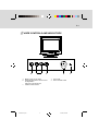
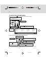
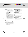
E-1
PACKING CONTENTS
The package contains:
• CRT monitor (M/T 6331)
• ac power cord
• User manual
UNPACKING
PROCEDURE
1
INTRODUCTION
This microprocessor-based, digital control 15-in.
color monitor is a high-performance, easy-to-use
product. This monitor uses a mini-neck CRT to
reduce power consumption during normal operation.
It also employs the latest on-screen-menu technology.
The microprocessor capability offers 13 most
commonly used factory-preset VESA timing modes,
and eight modes for the user to adjust to the special
timings that user might prefer.
This manual provides operating, usage, and safety
information for your monitor.
2
POWER SAVING
The monitor is driven to different power saving states
when it receives control signals from the display
controller. This process meets the Environmental
Protection Agency (EPA) Energy Star requirements
and reduces power consumption.
4
3
The monitor works in the following four states
according to the VESA-standard Display Power
Management Signal:
State
Power
Consumption
LED
Color
5
REPACKING
Save the origional box and all packing material for
future shipping needs.
* Packing materials and product are recyclable.
113393-0A-E.pm6
1
ON
Normal
Green
STANDBY
<15W
Yellow
SUSPEND
<15W
Yellow
OFF
< 5W
Amber
The power saving states are sustained until a control
signal has been detected or the keyboard or mouse is
activated. The recovery time from STANDBY/
SUSPEND state to ON state occurs within three
seconds. It usually takes less than 15 seconds from
OFF state back to ON state.
8/1/00, 6:38 PM
E-2
INSTALL THE
MONITOR
•
POWER CORD
To connect the tilt/swivel base to the monitor,
align hooks with the sockets on the bottom side
of the monitor, and gently push the base towards
the front of the monitor.
•
The 15-pin D-shell signal connector on the signal
cable connects easily to the video adapter output
on your computer. Lock both screws on the
connector to ensure a firm connection.
•
Turn the computer power switch to ON. Then turn
the monitor power switch to ON by pressing the
switch inward. The green power light-emitting
diode (LED) will light.
•
Allow about 30 seconds for the CRT tube to warm
up. Data will display on the screen.
•
If your display fails to function properly, refer to
the “Troubleshooting” section in this manual.
113393-0A-E.pm6
2
•
Check first to make sure that the power cord you
use is the correct type required for your area.
•
This monitor has a universal power supply that
allows operation in a 100/120 V ac or 220/240 V
ac voltage area. No user-adjustment is required.
•
First connect the power cord into your monitor
power input socket, and then plug the other end
into a 3-pin ac outlet. The power cord can be
connected to a wall outlet or the power output
socket on your computer, depending on the type
of power cord supplied with your monitor.
•
For units to be used at 120 V ac:
Use a UL-Listed Cord Set consisting of a
minimum No. 18 AWG, Type SVT or SJT threeconductor that is 4.5 m (15 ft) long and a parallel
blade, grounding-type attachment plug rated 10
A, 125 V.
•
For units to be used at 240 V ac (domestic use):
Use a UL-Listed Cord Set consisting of a
minimum No. 18 AWG, Type SVT or SJT threeconductor cord a maximum of 4.5 m (15 ft) long
and a tandem blade, grounding-type attachment
plug rated 10 A, 250 V.
•
For units to be used at 220/240 V ac (outside of
the United States):
Use a Cord Set consisting of a mininum No.18
AWG cord and grounding-type attachment plug
rated 15 A, 250 V. The cord set must have the
appropriate safety approvals for the country in
which the equipment will be installed and marked
HAR.
8/1/00, 6:38 PM
E-3
USER CONTROLS AND INDICATORS
a
b
c
a. Displays menu & exits menu
b. Scrolls through menu to choose an icon
for adjustment /
Adjusts level of selected icon
c. Confirms menu selection
113393-0A-E.pm6
3
2
1.
2.
Power LED
Power ON/OFF switch
8/1/00, 6:38 PM
1
E-4
USING THE ON-SCREEN MENU
1) Menu screen-press the 1 button to display the menu below and exit menus
Select mark
Press the
button to move the selection
mark to the desired location.
Adjustment icons
1:
CONTRAST
The item presently
being adjusted is
shown.
When the 2 button is pressed.
The selected adjustment screen appears.
:2
CONTRAST
BRIGHTNESS
H.SIZE
H.POSITION
V.SIZE
V.POSITION
PINCUSHION
TRAPEZOID
ROTATION
COLOR
LANGUAGE
DISP.FREQ.
DEGAUSS
RECALL
H.MOIRE
V.MOIRE
1:
CONTRAST
:2
2) Adjustment screen (example: horizontal position adjustment)
Name of adjustment screen
Adjustment icon
H .P OS ITION
50
/
1 :
The adjustment level is shown by both a number
and a bar. It can be varied with the front
buttons.
: 2
When the 2 button is pressed, the horizontal
size adjustment screen appears.
End Button
When the 1 button is pressed,
the adjustment level is stored,
the adjustment screen is ended
and the menu screen returns.
On the adjustment screen where these two adjustment
icons appear, it is possible to switch between the two
screens by pressing the 2 button.
NOTE: The amount of adjustment depends upon how long you depress the adjustment button. You might
have to tap the button to obtain the desired results.
113393-0A-E.pm6
4
8/1/00, 6:38 PM
E-5
INDIVIDUAL
ADJUSTMENT
VERTICAL SIZE adjustment
CONTRAST adjustment
Adjust the screen contrast to match your
personal perference.
Press the
button to decrease contrast and
press the button to increase it.
Direct operation: You can access the
CONTRAST adjustment
screen by pressing the
or
before entering the menu
screen.
Press the 2 key toggles between CONTRAST
and BRIGHTNESS.
Fills the viewable area vertically.
Press the button to make the image smaller,
or press the
button to make it larger. Press
the 2 key toggles between VERTICAL SIZE
and VERTICAL POSITION.
VERTICAL POSITION adjustment
Shifts the image on the screen vertically.
Press the
button to move it downward, or
press the button to move it upward.
Press the 2 key toggles between VERTICAL
SIZE and VERTICAL POSITION
PINCUSHION adjustment
BRIGHTNESS adjustment
Adjusts the brightness to get the desired
background level.
Press the
button to make the background
lighter, the button to make it darker.
Press the 2 key toggles between CONTRAST
and BRIGHTNESS.
HORIZONTAL SIZE adjustment
Fills the viewable area horizontally.
Press the button to make the image narrower,
or press the button to make it wider.
Press the
2
key toggles between
HORIZONTAL SIZE and HORIZONTAL
POSITION.
HORIZONTAL POSITION adjustment
Shifts the image on the screen horizontally.
Press the button to move the screen image to
the left, or press the button to move it to the
right.
2
Press the
key toggles between
HORIZONTAL SIZE and HORIZONTAL
POSITION.
113393-0A-E.pm6
5
The image can be corrected for barrel
distortion.
Press the button or the button to eliminate
curved vertical lines.
Press the 2 key toggles between VERTICAL
PINCUSHION and TRAPEZOIDAL
correction.
TRAPEZOID adjustment
The image can be corrected for the trapezoidal
distortion.
Press the
button to narrow the top edge, or
press the button to make the top edge wider.
Press the 2 key
toggles
between
PINCUSHION and TRAPEZOID correction.
ROTATION adjustment
The image can be corrected for tilt picture.
Press the button to tilt the image to the left,
or press the
button to tilt the image to the
right.
8/1/00, 6:38 PM
E-6
COLOR selection
The white in the image can be adjusted.
1) Use the
button to select: (1)9300O K,
(2)6500OK or (3)the user’s preferred color.
2) If the (3):the user’s color is selected, “2”
appears in the lower right of the On-Screen
Menu.
Press the front 2 button to display the USER
COLOR adjustment screen.
USER COLOR
The white in the video image can be adjusted
to the user’s preferred color.
1) Use the 2 button to select R (red) or B
(blue).
2) Use the
button to adjust the color as
desired.
*The GREEN color is fixed and cannot be
adjusted.
IMPORTANT-Memory recall of the user’s
color is not possible, so take note of the initial
setting before adjusting.
When the monitor is turned OFF, user color
keeps the last adjustment.
MANUAL DEGAUSSING
After moving the selector to the degauss icon,
press the 2 button. The degaussing action
takes place a few seconds later.
NOTE: A sharp snap noise may be heard when
degaussing occurs. This is normal.
MEMORY RECALL
It is possible to restore adjustments to the
original factory settings. If the monitor is
operating in a user defined mode, this control
has no effect.
HORIZONTAL MOIRE
Reduce the dark wavy line Moire pattern on
the screen.
Press the
or
button to minimize the
horizontal moire image on the screen.
VERTICAL MOIRE
Reduce the dark wavy line Moire pattern on
the screen.
Press the
or
button to minimize the
vertical moire image on the screen.
LANGUAGE selection
The language of the On-Screen Menu can be
selected among English, French, German,
Italian and Spanish. Select with the
buttons.
DISP. FREQ (Input frequency display)
This displays the input synchronization signal
frequency.
It identifies the horizontal and vertical
frequency sent to the monitor from the video
card currently in use.
113393-0A-E.pm6
6
8/1/00, 6:38 PM
E-7
TROUBLESHOOTING
If your monitor fails to operate functionally, it might
be possible to correct the problem by making simple
checks as follows:
Problem
Blank screen
(* NOTE)
Check and Adjust
·
·
·
SERVICING
Refer all servicing to qualified service personnel.
Serious shock hazards exist within the covers of
this monitor.
Do not open the covers under any circumstancesthere are no serviceable parts inside.
Monitor power switch,
power cord, signal cable,
or connector
computer power switch
Brightness and Contrast
controls
Display position
off-center
·
Display too small
or too large
·
Vertical and horizontal
size controls
Display too bright
or too dim
·
Brightness and Contrast
controls
SIGNAL CONNECTOR
INFORMATION
Vertical centering and
horizontal phase controls
Refer to the operation instructions for your computer
or video adapter to ensure that you have the correct
signal output source for the monitor. Ensure that the
switches on the video adapter are set correctly for
operation with this monitor.
If the above steps fail to correct the problem contact
your dealer for servicing by qualified service
personnel.
You must include the power cord if you return the
monitor for service.
* NOTE: You can easily distinguish the problem is
on the monitor or on the computer by
using the monitor’s built-in selftest
function.
With the monitor power ON, disconnect
the signal cable from monitor. If there is
no image on the monitor screen,
disconnect the signal cable. If you see a
“NO SIGNAL” image on the screen
(shown below), the monitor is function
properly, and the problem is at computer
side, or signal cable.
5
1
15
P in
F unc tio n
P in
1
Red signal
9
F unc tio n
5V
2
Green signal
10
Digital ground
3
Blue signal
11
Ground
4
Ground
12
SDA (DDC 1/DDC 2B)
5
* (N OTE)
13
Horizontal
Synchronization
6
Red return
14
Vertical synchronization
and VC LK (DDC 1)
7
Green
return
15
SC L (DDC 2B)
8
Blue return
*NOTE : This pin is used for self-test detection; at
computer side, this pin has to be connected
to ground.
N O S IGN AL
113393-0A-E.pm6
7
8/1/00, 6:38 PM
E-8
TECHNICAL SPECIFICATIONS
S c r e e n S iz e
1 5 - in . v is u a l d ia g o n a l
V ie w a b le s c re e n s ize 1 3 . 8 "
A nt i- G la r e C o a t ing * *
P o w e r I n pu t
V o l ta g e
F re qu e nc y
D o t P i tc h
0 . 2 8 m m (0 . 0 1 in. )
C ur re n t
R a t in g
1 .8 A
Powe r
C o n s u m pt i o n
7 0 W (m a ximu m )
D is pl a y A r e a
D e fault
F ul l S c a n
(H x W)
1 9 6 x 2 6 2 mm
( 7 . 7 x 1 0 . 3 in . ), t y p ic a l
2 11 x 2 8 2 mm
( 8 . 3 x 1 1 . 1 in . ), d e p e nd s
o n s ig na l tim in g
1 00 to 2 40 V A C
5 0 - 60 H z
D is pl a y C o l o r s
I nfin ite
D im e n s io n
371 x 391 x 399 mm
(14.6 x 15.4 x 15.7 in.)
M a x . R e s o l u ti o n
1 0 2 4 D o t s x 7 6 8 L in e s
We ight
1 3 . 5 k g (2 9 . 5 lb )
C o m p a t ib i li ty
A ll g r a p hic m o d e s w ith
h o r iz o nt a l fr e q u e n c ie s
b e t w e e n 3 0 K H z to 6 9
K Hz
O pe ra t in g
T e m p e r a t u re
1 0 ° C t o 3 5 °C
( 5 0 °F to 9 5 ° F )
S to ra g e
T e m p e r a t u re
- 2 0 °C to 4 5 ° C
( - 1 6 ° F t o 11 3 °F )
S y n c h r o n i za ti o n
H o r iz o nt a l:
V e r ti c a l :
3 0 to 6 9 K H z
5 5 to 1 2 0 H z
B a n dw i dt h
9 4. 5 M Hz
H um id i ty
2 0% to 8 0%
( no n- c o n d e n s in g)
I np ut S i g n a l
V id e o R G B A n a lo g
S yn c . T T L S e p a r a te
A lt it u de
U p to 2 1 3 3 . 6 m
( 7 0 0 0 ft)
S ig na l C a b l e
1 5 - p in D - s u b c o n ne c t o r
M PR I I / TC O
M P R 1 9 9 0 :1 0 ,
TC O 9 5 / 99
O p t io n a l
*
Specifications are subject to change without notice.
** TCO version has a different surface treatment.
*** This product is ERGONOMICS APPROVED.
113393-0A-E.pm6
8
8/1/00, 6:38 PM
E-9
PRESET MODES
M ode
R es olution
(H x V)
H. Freq.
(KHz)
V. Freq.
(Hz)
M ode
R es olution
(H x V)
H. Freq.
(KHz)
V. Freq.
(Hz)
1
720 x 400
31.4
70
8
1024 x 768
48.3
60
2
640 x 480
31.4
60
9
800 x 600
53.6
85
3
640 x 480
35.0
66
10
1024 x 768
56.4
70
4
800 x 600
37.8
60
11
1024 x 768
60.0
75
5
640 x 480
37.5
75
12
1280 x 1024
64.3
60
6
640 x 480
43.3
85
13
1024 x 768
68.6
85
7
800 x 600
46.8
75
113393-0A-E.pm6
9
8/1/00, 6:38 PM