1
i-data Electronic Documentation
The i-data Printing Solutions
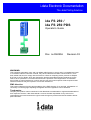
ida FS 250 /
ida FS 250 PDS
Operator’s Guide
Doc. no D60256
Revision 03
WARNING:
This equipment generates, uses, and can radiate radio frequency energy and if not installed and used
in accordance with the instruction manual, may cause interference to radio communications. It has
been tested and found to comply with the limits for a Class A computing device pursuant to Subpart
B of Part 15 of FCC Rules, which are designed to provide reasonable protection against such interference when operated in a commercial environment. Operation of this equipment in a residential
area is likely to cause interference in which case the user at his own expense will be required to take
whatever measures may be required to correct the interference.
EMC directive:
This product observes the rules and regulations of the EMC directive. If so required, a declaration of
conformity in local language stipulating the applied rules and regulations can be obtained.
Trademarks:
Company and product names mentioned in this datasheet are trademarks or registered trademarks of
their respective owners. i-data international a-s cannot be held responsible for any technical or
typographical errors and reserves the right to make changes to products and documentation without
prior notification.
ida FS 250, Operator's Guide
Document No.: D60256-03
© Copyright i-data international a-s 1997
i-data international a-s
Vadstrupvej 35-43
DK-2880 Bagsvaerd
Denmark
Telephone:
+45 44 36 60 00
Telefax:
+45 44 36 61 11
E-mail: i-data i-data.com
WWW: http://www.i-data.com
SUBSIDIARIES
i-data Denmark
Vadstrupvej 35
DK-2880 Bagsvaerd
Denmark
Telephone:
+45 44 44 77 50
Telefax:
+45 44 44 85 50
i-data Sweden
Datavägen 21
S-43600 Askim
Sweden
Telephone:
+ 46 31 680710
Telefax:
+ 46 31 682670
i-data UK Ltd.
Unit 3, Cartel Business Centre
Stroudley Road
Basingstoke, Hants RG24 8FW
United Kingdom
Telephone:
+ 44 1256 460033
Telefax:
+ 44 1256 460066
i-data France
Parc de Haute Technologie
2, rue Alexis de Tocqueville
92183 Antony Cedex
France
Telephone:
+ 33 1 46114340
Telefax:
+ 33 1 46114341
i-data, Inc.
250-V Executive Drive
Edgewood
New York 11717
U.S.A.
Telephone:
+1 (516) 243-6600
Telefax:
+1 (516) 243-6500
i-data Australia Pty. Ltd.
14, Gipps Street
Collingwood, Victoria 3066
Australia
Telephone:
Telefax:
+ 61 3 4195877
+ 61 3 4195610
About i-data
Founded in 1981 to provide direct attachment of PC laser printers in SNA
environments, i-data has grown to become the world leader in printer
connectivity technology. With the advent of network attached printers,
i-data expanded its product range to include comprehensive host-to-LAN
printing concepts, in addition to the traditional Coax and Twinax interfaces.
All i-data products are designed to complement IBM’s own printing strategy,
yet also provide the flexibility needed to conform to the specialised needs of
large enterprises.
i-data products and services are marketed worldwide through the company’s
comprehensive network of sales, offices and distributors.
-2-
Table of Contents
ida FS 250, Operator's Guide
Preface
September 1997
This manual applies to the ida FS 250 and the ida FS 250 PDS protocol
converters.
NOTE:
Both products: “ida FS 250” and “ida FS 250 PDS”
will be referred to as “ida FS 250” unless specific
reference is made to the IPDS functionality of the ida
FS 250 PDS.
The ida FS 250 supports twinax Centronics and RS232 inputs. The default
output is Centronics.
The manual describes how the ida FS 250 is connected and oper ated. Read it
before you start using the protocol conver ter and keep the manual in a safe
place for future referen ce.
It is assumed that the reader has a basic knowledge and under standing of
IBM computer systems, especially the IBM 5250 Information Display System.
It is also assumed that the reader has adequate knowledge of the printer
which is going to be connected to the ida FS 250.
The ida FS 250 can be used with all PCL 4/5 printers .
Related Manuals
ida FS 250 PDS
"MakeITDS"
Document No.: D60253
“MakeITDS for VM/MVS, Setup Guide”
Document No.: D60272
Both FS converters
"5250 Programmer's Guide"
Document no. D62079.
-3-
Table of Contents
ida FS 250, Operator's Guide
As the ida FS 250 emulates the IBM 3812 printer in IBM 5219 emulation, useful
information may be obtained from:
"IBM 5219 Printer, Models DO1/DO2, Programmer's Reference Guide"
IBM Order no. GA 23-1025
"Using the IBM Page printer 3812 with an IBM System /36 or System /38"
IBM Order no. S544-3343
"AS/400 Device Configuration Guide", IBM Order no. SC21-8106
-4-
Table of Contents
ida FS 250, Operator's Guide
Table of Contents
Preface................................ ................................ ................................ ....................... 3
Related Manuals ................................ ................................ ................................ . 3
Table of Contents................................ ................................ ................................ ...... 5
Kit Contents................................ ................................ ................................ ............... 7
1. Introduction to ida FS 250................................ ................................ .................... 8
1.1 Introduction to ida FS 250 ................................ ................................ ............ 8
1.2 ida FS 250 Product Features ................................ ................................ ........ 8
1.3 Supported Control Units ................................ ................................ ............... 9
2. Installation Requirements................................ ................................ .................. 10
2.1 Environment requirements ................................ ................................ .......... 10
2.2 Pre-Installation Requirements ................................ ................................ .... 10
2.2.1 National Language Selection ................................ .......................... 10
2.2.2 Paper Size (EU/US) ................................ ................................ ........ 11
3. Installation and Connections of the ida FS 250
................................ ................ 12
3.1 The Rear Panel ................................ ................................ .......................... 12
3.2 Emulation ................................ ................................ ................................ .... 14
3.2.1 Via the Address Switch ................................ ................................ ... 14
3.2.2 Via the Line ................................ ................................ ..................... 15
3.3 Upgrading to IPDS ................................ ................................ ...................... 16
3.4 Connecting the ida FS 250 to the Printer ................................ ................... 17
3.4.1 Connecting via Centronics output ................................ ................... 17
3.4.2 Connecting via RS-232 output ................................ ........................ 18
3.5. Connecting the ida FS 250 to System ................................ ....................... 19
3.5.1 Testing ................................ ................................ ............................ 20
3.5.2 Timeout ................................ ................................ ........................... 21
4. Operation of ida FS 250................................ ................................ ..................... 22
4.1 ida FS 250 top panel ................................ ................................ .................. 22
CU ................................ ................................ ................................ ............ 22
PAR (Parallel input) ................................ ................................ ................. 22
SER (Serial input/output) ................................ ................................ ......... 23
READY (Printer Ready) ................................ ................................ ........... 23
5. Specifying Share Timeout and String................................ ............................... 24
6. idaSetup - IPDS Programming................................ ................................ ........... 26
7. IRQ Handling................................ ................................ ................................ ....... 27
8. Programming ida FS 250 - non-IPDS
................................ ................................ . 28
8.1 The Escape Character ................................ ................................ ................ 28
8.2 Defining a Temporary Escape Character ................................ ................... 29
8.3 Syntax of an FSL Function ................................ ................................ ......... 29
8.4 Invalid Escape Character ................................ ................................ .......... 29
8.5 Setup Functions supported (PCL Mode) ................................ .................... 30
-5-
Table of Contents
ida FS 250, Operator's Guide
8.6 Quick Reference Guide of Supported FSL Functions ................................ 32
9. Programming via Shareport................................ ................................ ............... 43
9.1 Updating firmware ................................ ................................ ...................... 45
10. Errors and Recovery................................ ................................ ......................... 46
10.1 ida FS 250 Error Messages ................................ ................................ ...... 46
10.1.1. Two Devices with Same Address ................................ ................. 46
Appendix A: Use of ida FS 250 Serial Port
................................ ........................... 47
Appendix B: Test Printout................................ ................................ ...................... 48
Appendix C: Default GFID Table................................ ................................ ............ 49
Scalable Fonts ................................ ................................ ................................ .. 51
Appendix D: i-data Product Platform................................ ................................ .... 53
Index................................ ................................ ................................ ......................... 56
-6-
Kit Contents
ida FS 250, Operator's Guide
Kit Contents
Please check that your kit is complete with the following:
ida FS 250
•
ida FS 250 converter
•
Wall plug power supply
•
Parallel printer cable
•
Auto-terminating twinax T-cable
•
Product documentation (electronic format):
ida FS 250 / ida FS 250 PDS Operator's Guide; Doc. no. D60256
•
Product documentation (hardcopy format):
ida FS 250 / ida FS 250 PDS Quick Guide; Doc. no. D10256
ida FS 250 PDS
•
Same contents as above except converter comes equipped with IPDS
module
In addition the following i-data accessories can be used:
•
Parallel input cable (Order no. 999008 030)
•
Serial input cable (Order no. 999010 030)
•
Serial output cable has to be ordered for the specific printer you are
going to connect to. Please contact your i-data dealer for more details.
(See also Appendix A)
•
PC printer share cable (Order no. 999022-030)
IPDS Upgrade Kit
• IPDS option (for upgrade), ida PDS Supra (Order no. 993011-001)
-7-
Introduction
ida FS 250, Operator's Guide
1. Introduction to ida FS 250
This chapter gives a short description of the ida FS 250 converter
1.1 Introduction to ida FS 250
The ida FS 250 is a protocol converter which enables any printer to be
connected to an IBM computer system. See Section 1.3, Supported Control
Units, for information on the IBM systems to which the ida FS 250 connects.
The printer or device should have either a Centronics Parallel connector or an
RS 232 serial connector in order to be con nected to the ida FS 250 protocol
converter.
1.2 ida FS 250 Product Features
The ida FS 250 protocol converter gives you the following fea tures:
•
Autoconfiguration of printers with minimum PCL4 and PJL,
supporting IEE1284, Bidirectional Centronics Communication.
This automatically configures
• Paper size
• Paper tray
• Duplex (IPDS)
• Memory (IPDS)
To enable the automatic configuration, use function 119.
Non-IPDS:
•
Support of 5224, 5225, 5256, 4234, 4245/6262 printer emulations as
alternatives to 3812/5219
•
Twinax setup via share port
•
Flash prom allowing downloading of new firmware via the twinax or the
Centronics port
•
Support of ida PSS
•
Automatic input sharing between Twinax, Centronics and RS 232 serial
input ports
•
Support of duplex printing
•
Support of bar code printing
-8-
Introduction
ida FS 250, Operator's Guide
•
Support of Automatic Page Orientation
IPDS:
IPDS support - IBM 4028 and 3812 or 3816 emulation.
• Non-IPDS support via the installed i-data interface card, with full
emulation of IBM3812/5219/3816 and IBM 5224/ 5225/5256/4234.
• Support of the ida PSS software package
• Support of the i-data Function Selection via the Line (FSL) facility in
non-IPDS mode.
• Automatic input sharing between Twinax, Centronics and RS-232 input
ports.
• Flash prom allowing downloading of new firmware via the centronics
port.
• Multiple VPA (Valid Printable Area) check options available.
• IM Smoothing (3812 and 3816 emulations).
1.3 Supported Control Units
The ida FS 250 will connect to the following control units :
•
IBM /34
•
IBM /36, all models
•
IBM /38, all models
•
IBM AS/400
•
IBM 5294 and 5394 remote controllers
-9-
Connecting to System
ida FS 250, Operator's Guide
2. Installation Requirements
Before connecting the ida FS 250, you should check the requirements
described in this chapter.
2.1 Environment requirements
The ida FS 250 protocol converter can be installed in the following
environment:
•
Temperature range from 10 ° - 40°
•
Humidity between 8-80 %, non-condensing
•
Power consumption: 120 and 220 Volt version - max. 21.5 VA
WARNING!
The equipment must be grounded. Operation with
out a
ground may cause exposed metal parts to carry main voltage.
This can lead to malfunction and personal injury.
2.2 Pre-Installation Requirements
Prior to installation and connection you must first make sure that you have
set the desired national language - do this via the line (activating function
Y8). See the section: National Language Selection.
2.2.1 National Language Selection
Via the Line (Function 8)
Below is a short description of how you change national language via the line
(Function 8). For further details on programming the ida FS 250, please see
the chapter: Programming ida FS 250.
The commands shown in Figure 1-1 have to be sent to the ida FS 250 . You
can either do this in a file you transmit to the printer or by entering the
command sequence on your screen and making a local copy (print screen).
-10-
Connecting to System
ida FS 250, Operator's Guide
&&??%
(defines % as temporary ESC character)
%Y8,<number of new language>%
(selects language)
%X1
(saves setup)
Changing Language via the Line
Your can select between the following languages:
Option
37
256
273
274
275
276
277
278
280
281
282
283
284
285
297
500
871
Description
English (US) EBCDIC
International
Austrian/German
Belgian
Brazilian
Canadian French
Danish/Norwegian
Finnish/Swedish
Italian
Japanese (English)
Portuguese
Spanish Speaking
Spanish
English (UK)
French
Multinational
Iceland
NOTE: Factory default depends on the settings on the DIP switch bank; i.e.:
EU = multinational
US = English (US) EBCDIC
2.2.2 Paper Size (EU/US)
When you receive the ida FS 250, the interface is already in the box and
is ready to connect to the system and to the printer. From the factory, the
ida FS 250 is set up for either US (Letter) or European (A4) paper size
depending on what you specified when ordering the ida FS 250.
In the event that you should have to change this setting, please contact
your point of purchase for instructions.
-11-
Connecting to System
ida FS 250, Operator's Guide
3. Installation and Connections of the
ida FS 250
This chapter starts with an overview of the functionality of the rear panel.
Then follows a description of how you connect the ida FS 250 box to a
printer and finally you will find instructions for connection to a system.
NOTE:
Before you start the installation, make sure that you set the address
switch and the desired emulation. See the description in the section
:
Emulation.
3.1 The Rear Panel
RS232
ADDR
PARALLEL IN
PARALLEL OUT
12-18 VDC.
12 3
4
0
5
B
AT6
+
--
0.7A
A = PCL
Fig 2-1 ida FS 250 Rear Panel
PARALLEL OUT
The parallel output port is connected to the parallel/Centronics in put port
on the target printer (standard parallel out cable supplied with printer
should be used).
PARALLEL IN
The parallel input port can be connected to the parallel/Centronics out put
on a PC or similar source which enables it to share the printer with the
host. For this connection you need a spare part cable ending in a 25-pole
D-Sub connector (i-data order no. 999022 030).
SERIAL (IN/OUT)RS232
The serial port can be configured either as input or as output.
Default configuration is input.
Serial input
The serial port is connected to the serial output on a PC or similar source able
to share the printer with the host.
-12-
Connecting to System
ida FS 250, Operator's Guide
For this connection you need a spare cable ending in a 25-pole RS connector
(i-data order no. 999010 030).
Y24 = 0 is also To use the serial input, Function 24 Data Input/Output Port Select must be set
used for
to zero (which is factory default).
Centronics
output.
On the PC you must also make the following settings to match the default
settings on the box:
Function Y15: Baud rate, set to 5 = 9600
Function Y16: Number of data bits, set to 8 = 8 bits
Function Y17: Parity, set to 1 = No Parity
Function Y18, Number of Stop Bits, set to 1 = 1 Stop Bit
If this is not possible, you must change the functions 15, 16, 17 and 18 on the
box to match the PC's values.
NOTE:
Programming of functions 15, 16, 17, 18 and 24 is not possible via the
serial port. These functions have to be programmed either via the twinax
or via the parallel input port.
TWINAX CONNECTOR
Before the twinax cable is connected, be sure to turn the box power
OFF.
When power is turned off, plug the automatically terminating twinax
T-cable into the socket on the rear panel and turn the connector ring
clockwise to lock.
ADDRESS SWITCH: EMULATION & PRINTER DRIVER SELECTION
You use the address switch for selecting/changing emulation, setting
the address and for generating test printouts. Tests can also be
made via the line. See the section Testing for details.
For details on emulation see the section : Emulation
The switch is also for future printer driver selection. Note that the
device is set to PCL mode as a default which is the only supported
printer driver mode. Do not attempt to change this.
-13-
Connecting to System
ida FS 250, Operator's Guide
3.2 Emulation
As a default the ida FS 250 will emulate IBM 3812/5219/3816.
The ida FS 250 PDS emulates IPDS as a default.
You can select emulation in two ways. Either via the address switch or via the
line using FSL function Y37.
The following emulations are supported by the ida FS 250:
IBM 3812/5219/3816
IBM 5224
IBM 5225
IBM 5256
IBM 4234
If you wish to see the current emulation, you can generate a test printout by
turning the address switch to the T-position.
3.2.1 Via the Address Switch
Emulation selected on the address switch is described below.
The T-cable must be disconnected from the converter before changing
emulation.
NOTE: Make sure that you have set the address switch before you switch
power on.
Select emulation on the address switch as follows:
1. Switch off the box.
2. Turn the address switch to the "T" position. Switch on power to box.
3. When the ida FS 250 is ready, it will eject a page with the following
message:
"Current emulation is xxxx"
4. When the address switch is turned to a new position, a new message
stating the current emulation will be printed after a few seconds.
5. When the desired emulation has been set, you must switch power off and
set the address correctly again (values 0-6). Select one of the following
emulations shown below.
-14-
Connecting to System
ida FS 250, Operator's Guide
Non-IPDS
Selection
*0
1
2
3
4
5
Emulation
3812 / 5219 / 3816
5224
5225
5256
4234
3812/5219/
3816
* default value
Matrix printers
Selecting emulation via address switch
6. Connect the twinax cable and switch power on.
7. Activate the "T" position again and check that the emulation and address
switch have been changed. (See the settings printout). See the section:
Testing.
Check whether the configuration complies with the requirements of your
installation and print jobs.
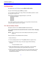
3.2.2 Via the Line
You can set the desired emulation in FSL function Y37 1.
Note that if you select emulation via function 37, you must physically write
the emulation. See the chart in the following for details.
E.g.
%Y37,5224%
will select emulation 5224
%Y37,3812%
will select emulation 3812/5219/3816
Below you will find information on the emulations which can be selected in
the n1 parameter of function Y37.
NOTE:
Please note that you have to WRITE the parameter you require
(shown in "Write" column).
Non-IPDS
1For
further details on programming the ida FS 250, please see the chapter:
Programming ida FS 250.
-15-
Connecting to System
ida FS 250, Operator's Guide
Y37,n1
Write
3812
5224
5225
5256
4234
Emulation
*3812 / 5219 / 3816
5224
5225
5256
4234
* default value
SCS printers
Selecting emulation via the line
The default configuration of the ida FS 250 can be used for most
application programs and uses. You should only change the address and
the emulation. The rest of the settings should only be changed if you have
special requirements.
3.3 Upgrading to IPDS
If you need to upgrade your ida FS 250 with the IPDS module, please
follow these instruction before proceeding with the installation.
1. Unscrew the 4 screws from the bottom of the converter.
2. Place you hands on each side of the box, bottom facing down and the
rear panel facing you. Carefully press open the top cover of the
converter.
3. Place the IPDS module (main component side facing up) on the PCB of
the box. Note that the connector has to be placed on top of the PCB’s
connector (to the right on the PCB).
4. Make sure the plastic supports fit in the holes of the IPDS module.
5. Press the module gently into position and, while still facing the rear
panel, place the top cover precisely above the bottom cover so that all
edges are aligned. Press the top cover gently into a locked position.
6. Re-insert the screws and fasten.
7. Now proceed to the actual installation of the converter to the printer
and the system.
-16-
Connecting to System
ida FS 250, Operator's Guide
3.4 Connecting the ida FS 250 to the Printer
CAUTION:
All connections to theida FS 250 protocol converter should be
made while the power is switched OFF to both the printer and
converter.
3.4.1 Connecting via Centronics output
Connecting the ida FS 250 to the printer is done by following these steps:
1. Check that the printer's parallel input port is available on printer.
2. Connect the cable supplied with the product between the printer's parallel
input port and the protocol converter's PARALLEL OUT port.
3. Power on the printer and the ida FS 250.
4. Turn the address switch (on the rear panel) to the "T" position . A settings
printout will be generated and the CU indicator will start flashing.
The interface can be set up in many ways. From the factory, the interface
has been set up to cover most needs and uses. Appendix B.: "Test
Printout" is a sample printout of settings and is just one way of setting up
your interface.
Keep the settings printout you make together with this manual for future reference.
If the printout format does not match the test printout in Appendix B., or if
nothing was printed, this means that the printer setup does not match the
protocol converter setup. Contact your systems support personnel or your
i-data dealer for assistance.
5. When the printout is in order, you proceed to the chapter: Connecting ida
FS 250 to System.
-17-
Connecting to System
ida FS 250, Operator's Guide
3.4.2 Connecting via RS-232 output
Note: This does not apply for the ida FS 250 PDS
1. To use the RS-232 port as an output por t you must set function Y24 to 1.
(For further details on programming the ida FS 250, please see the chapter
Programming ida FS 250).
If possible, the serial output device you are connecting has to be set to
Baud rate = 9600, Number of data bits = 8, No parity and 1 Stop Bit to
match the default settings of the box. If this is not possible, you must
change the functions 15, 16, 17 and 18 to match the settings of the serial
output device.
2. The cable you need for connecting the serial output device to the serial
port on the box must be ordered from your point of purchase especially for
the serial output device.
NOTE:
Programming of Functions 15, 16, 17, 18 and 24 is not possible via the
serial port. These functions have to be programmed either via the
twinax port or via the parallel input port.
For full details on the FSL functions (Y functions), see the " 5250
Programmer's Guide; Document No.: D62079.
3. Power on the printer and the ida FS 250.
4. Turn the address switch on the rear panel t o the T-position..
A settings printout will be generated and the CU indicator will start
flashing.
The interface can be set up in many ways. From the factory, the interface
has been set up to cover most needs and uses. Appendix B.: Test Printout
is a sample printout of settings.
Keep the settings printout together with this manual for future reference.
5. If the connection between the printer and the protocol con verter does not
work properly, the reason is probably that the
Y functions 24, 15, 16, 17 and 18 do not match the values of the printer.
-18-
Connecting to System
ida FS 250, Operator's Guide
If the printout format does not match the test printout in Appendix B. or if
nothing was printed, this means that the printer setup does not match the
protocol converter setup. Contact your systems support personnel or your
i-data dealer.
6. Power OFF and ON the ida FS 250 and check that all indicators light up
momentarily.
7. Proceed to the chapter: Connecting ida FS 250 to System.
3.5. Connecting the ida FS 250 to System
After a successful test printout has been generated to establish that the
connection between the ida FS 250 converter and the printer is working
correctly (see previous section), you are now ready to connect the ida FS
250 to the system.
WARNING:
All connections to theida FS 250 protocol converter
should be made while the power is switched OFF.
1.
Turn off the power and connect the ida FS 250 to your host system
using the twinax cable, and the auto-terminating T-cable.
2.
When the connection has been made, tu rn power ON and check that
the CU and READY indicators turn ON. When they do, you have
completed the installation procedure and are ready to operate the
protocol converter as described below.
What if the CU Indicator fails to turn on?
If the CU indicator does not turn ON, this means that there is no
communication with the control unit. You should check the follow ing:
a. The twinax cable connection from the control unit to the ida FS 250.
b. The control unit (is it powered up etc.)
c. Is the control unit supported by the ida FS 250 ?
(See the section. Supported Control Units, for a list of sup ported control
units).
-19-
Connecting to System
ida FS 250, Operator's Guide
If all three (a. b. and c.) are in order, contact your systems support personnel
or your point of purchase.
3.5.1 Testing
The test printout pages can be generated in two ways - via the address switch
or via the line activating the T function . For details on the T function, please
see the section: Quick Reference Guide of the Supported FSL Functions.
Test via the address switch
1. Turn the address switch to the "T" position. A settings printout will be
generated (test 4).
2. Turn the switch away from the T-position.
3. When the CU indicator flashes, turn the switch back to the T-position.
4. The printer will now enter Online HEX Dump mode and print all data
received in on-line HEX dump format ( test 1).
5. Hex dump mode is terminated by turning the address switch to its power up
position.
Keep the settings printout together with this manual for future reference.
Finally, a settings printout can also be generated at power on by activating
function Y120. See the Section: Quick Reference Guide of the Supported
FSL Functions for details.
NOTE:
When installing the interface, it is recommended that you carry out Test
4, Settings Printout, to check whether the printer is set to the correct
language. If the language is incorrect, contact your systems support or
your point of purchase.
-20-
Connecting to System
ida FS 250, Operator's Guide
3.5.2 Timeout
The ida FS 250 enables printer sharing between the system and a PC. For
this purpose it is possible to specify a timeout period.
If the printer is receiving input on the parallel port, for example, and there is
a break in the transmission of data, the other input ports will not be polled for
the period speci fied.
The factory default timeout is 20 seconds
. The timeout may be changed
to suit your requirements. This is done by sending a new setup to the ida FS
250 input port where you want it to take effect.
When specifying the timeout it is also possible to specify a user string. A
user string may be used for changing from one symbol set (e.g. Roman 8) to
another (e.g. IBM-PC8), for example.
NOTE:
Settings on the twinax input port are automatically reestablished after
another input port has been using the printer.
On the parallel and RS input port, you have to pro
gram the required
setup yourself.
For more detailed information on the commands required, see the chapter:
Specifying Share Timeout and String.
-21-
Specifying Share Timeout and String
ida FS 250, Operator's Guide
4. Operation of ida FS 250
The ida FS 250 top panel has been designed to register the operation of the
box via the four following indicator LEDs :
•
CU (contact to control unit)
•
PAR (parallel input)
•
SER (serial input)
•
READY (printer)
4.1 ida FS 250 top panel
CU
The CU indicator has 3 states which signal the following:
State
ON
BLINKING
OFF
Indication
Contact with the control unit.
In test mode.
No contact of the control unit, or the contact
has been broken for more than 1 minute.
PAR (Parallel input)
The indicator LED has 2 states:
State
ON
OFF
Indication
Indicates that the box is processing data from the
Centronics parallel port
Indicates that the box is idle or processing data from
the twinax/RS232 inputs
-22-
Specifying Share Timeout and String
ida FS 250, Operator's Guide
SER (Serial input/output)
The indicator LED has 3 states
State
ON
BLINKING
OFF
Indication
Indicates that the box is processing data from the RS232 Serial input
Indicates that the box has defined the RS-232 as
output for the box.
Indicates that the box is idle or is processing data from
the twinax/Centronics inputs.
READY (Printer Ready)
The indicator LED has 3 states:
State
ON
BLINKING
OFF
Indication
Indicates that the connected printer is ready; i.e. that
printer's "Select" condition is active and the "PE"
signal is inactive. If the connected printer is an RS 232
printer, the ready validation is done by the "DTR"
signal.
The printer is not ready and print may be pending
in the buffer.
Indicates that the connected printer is not ready for
data input.
-23-
Specifying Share Timeout and String
ida FS 250, Operator's Guide
5. Specifying Share Timeout and String
In order to specify the timeout for a specific input port, an FSL ( Function
Selection via the Line) sequence must be sent to the port in question. To do
this a temporary Escape (ESC) Character must be defined first. This is done
in the following way:
&&??<character>
The sequence "&&??%" will define " %" as the ESC Character.
Timeout is specified in FSL Function 100 . This function has the following
syntax ("%" is the ESC Character):
%Y100,<timeout>[,user string]%
Factory default = 20 seconds
Timeout:
1 to 255 indicating number of seconds
User string:
Optional - string in HEX to be sent to the
printer before transmission of data, when the
printer is selected by the share unit.
If function 100 is sent to the twinax, a user
string number can be defined instead of a
HEX string. The user string then has to be
defined in function 61.
NOTE:
The Timeout string must be written in ONE line (see example below).
The user string and settings will only be sent if a share condition has
occurred.
The new setup must be saved in the NVRAM with the following command
("%" is the ESC Character):
-24-
Specifying Share Timeout and String
ida FS 250, Operator's Guide
%X1
NOTE:
%X1 will delete the temporary escape character.
The FSL string above was split up into several lines for reasons of
clarification to simplify the explanation of the different functions. Below is an
example where the FSL string is typed in one line.
Example:
&&??%%Y100,30,1B,45%%X1
The FSL string above has the following effect:
•
•
•
•
Defines % as ESC character
Sets timeout to 30 seconds
Send 1B 45 HEX (RESET) before the next data transmission.
Saves setup in the NVRAM and deletes "%" as escape character
NOTE:
FSL 100 works on the port it is sent to. If it is sent to the parallel or serial
input port, the string containing the Function 100 programming will be
printed when it is sent to the ida FS 250.
-25-
IPDS Setup
ida FS 250 PDS, Operator's Guide
6. idaSetup - IPDS Programming
NOTE:
This chapter only applies to the converter when
mounted with an IPDS module.
idaSetup is a program developed with the purpose of setting up the wide
range of IPDS protocol converters via a PC share port or from a host.
For details on how to configure the IPDS parameters for the
ida
FS 250 PDS using the program idaSetup, see the separate
documentation for this, “IPDS Programmer’s Guide”, doc. no.
D60253. The manual is available as an electronic document.
-26-
Programming
ida FS 250, Operator's Guide
7. IRQ Handling
This section describes how to recover from various IRQ conditions.
•
•
•
Paper jam
Out-of paper
Stacker full
The printer will recover from these conditions without loss of data as long
as you do not power off the printer.
•
Printer Not READY
The ida FS 250 PDS will detect if the printer is NOT READY and will
interrupt data transmission to the printer. If the printer is OFFLINE (i.e. not
READY) there will be no data loss as long as you do not power off the
printer.
•
Out of toner
This condition is indicated by the printer's front panel. If printing
continues, the print quality may not be acceptable. There will be
no loss of data as long as you do not power off the printer
.
•
Door Open
This condition is indicated by the printer's front panel. There will be
no loss of data as long as you do not power off the printer
•
Printer Power Off
You should not power off the printer, unless you power off the box as well.
If only the printer is powered off, unpredictable results may occur.
-27-
Programming via Shareport
ida FS 250, Operator's Guide
8. Programming ida FS 250 - non-IPDS
The ida FS 250 works using a large number of internal Setup Functions (FSL
Functions). FSL setup functions can be sent either from your IBM system or
from a PC.
When the protocol converter has been installed and connected to a printer,
you may have to consider the use of these setup options.
The factory default setup will meet the demands of most host systems and
users, and special programming is therefore normally not required.
However, special circumstances may require changes in the pro gramming of
the box. For full details on this please see the "5250 Programmer's Guide;
D62079". In the Programmer's Guide you will find an extensive description of
the FSL Functions with notes, comments and examples.
NOTE:
This section is a brief description of how to set up the interface with FSL
functions from the line. The section is primarily aimed at users who are
already familiar withi-data products.
8.1 The Escape Character
No escape character is defined when you receive the ida FS 250 from the
factory. When you send FSL Functions via the data stream, the functions
must be "separated" from the data stream, so that they are not printed. For
this you need to define an Escape (ESC) Character.
The ESC Character tells the interface that the characters following the ESC
Character in the data stream are to be regarded as a command. The
command string must also end with the ESC Character .
Before you define the ESC Character please note the following:
• Once the ESC character has been defined, it cannot be printed. For
this reason you must select a character which will not normally appear
in the data stream. If the character defined appears elsewhere in the
data stream (i.e. outside an FSL Function), the interface will regard it
as an ESC character and you will get a syntax error.
• However, you need not have an ESC Character defined all the
time. When it has served its purpose you can remove it again.
-28-
Programming via Shareport
ida FS 250, Operator's Guide
8.2 Defining a Temporary Escape Character
The ESC Character may be defined as a temporary as well as a
permanent ESC Character.
Below see how to define "%" as a temporary ESC Character.
&&??%
Defining "%" as a temporary ESC Character
.
Since the temporary ESC Character is defined in the temporary memory
(RAM) alone, it is only in effect as long as the printer is switched on - or until
you remove it again. To remove it you define it as "space".
&&??<space>
Removing the temporary ESC Character
NOTE:
For information on how to define a permanent ESC Character,
please refer to the 5250 Programmer's Guide; D62079.
8.3 Syntax of an FSL Function
The special sequence that the interface will interpret as an FSL Function
as shown below:
%Y<function number>,<parameters>%
Syntax of an FSL Function. "%" is the defined ESC Character
8.4 Invalid Escape Character
The error message "Invalid Escape Sequence" will be printed on paper if an
invalid escape sequence has been sent to the printer.
Recovery:
Locate and correct the error in your setup file.
-29-
Programming via Shareport
ida FS 250, Operator's Guide
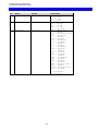
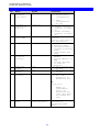
8.5 Setup Functions supported (PCL Mode)
No.
Description
Y2
Y3
Y8
Y10
Y11
Y12
Y15
Y16
Y17
Y18
Y19
Y21
Y24
Y48
Y51
Y59
Y61
Y62
Y73
Y74
Y75
Y88
Y89
Y90
Y91
Y92
Y93
Y94
Y96
Y97
Y98
Y100
Y119
Y120
Y249
T
LPI
CPI
LU1 Language
Page Format
Paper Path
Paper Size
Baud Rate for Serial Input
Number of Data Bits for Serial Input
Parity for Serial Input
Number of Stop Bits for Serial Input
Duplex Printing
Horizontal Compression and Vertical Scaling
Interface selection
Permanent Escape Character Selection
User Defined String(s) at Power Up
Bar Code Type Definition
Setup for User Defined Strings
Setup for IBM Defined Strings
Select Translate Table
Printer Symbol Set Definition Strings
Overwrite Translate Table
Physical Margin
Physical Margin Compensation
Define User Escape String
Font Definition
Font Point Size Definition String
Font Attribute Definition String
Font Typeface Definition String
Font Change Simulation
GFID/Font Selection
Automatic Page Orientation
Printer Share String and Timer
Autoconfiguration Select
Settings Printout at Power Up
Enter Engineering Mode
Initiate Test
T1 On-line Hex Dump
T3 ASCII Hex Dump
T4 Settings Printout
T5 Printout Translate Table
T6 Cancel ASCII Hex Dump
-30-
Programming via Shareport
ida FS 250, Operator's Guide
No.
Description
X
Save/Overwrite Settings
X1 Store Settings in Permanent Memory
X3 Restore Factory Default Settings
X4
Restore Settings from Permanent Memory
Send User String
Send User String
Send Bar Code (as defined in Y59)
Program Flash Prom
Z
S
W
P
ESC Features:
%%
Special transparent feature (Multiple paired Hex transparent).
e.g.: %%1B45%
where % is the defined ESC character.
%
Special transparent feature (Single paired Hex transparent).
where % is the defined ESC character.
-31-
Programming via Shareport
ida FS 250, Operator's Guide
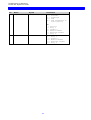
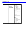
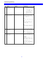
8.6 Quick Reference Guide of Supported FSL Functions
In this section the supported FSL Functions in twinax will only be described
with their syntax and parameters.
The notation below will apply to the following FSL Functions table:
%
is the defined escape character
*
factory default
< >
mandatory parameter which must be defined
[ ]
optional pa rameter which can be defined
-32-
Programming via Shareport
ida FS 250, Operator's Guide
No.
2
Name
LPI
Syntax
%Y2,<n1>%
3
CPI
%Y3,<n1>%
8
Language
%Y8,<n1>%
Parameters
3 = 3 LPI
4 = 4 LPI
*6 = 6 LPI
8 = 8 LPI
5 = 5 CPI
*10 = 10 CPI
12 = 12 CPI
15 = 15 CPI
16 = 16.7 CPI
**37 = Engl. US
EBCDIC
256 = International
273 = Austrian/
German
274 = Belgian
275 = Brazilian
276 = Canadian
French
277 = Danish/
Norwegian
278 = Finnish/
Swedish
280 = Italian
281 = Japanese
(Latin)
282 = Portuguese
283 = Spanish
284 = Spanish
Speaking
285 = English (UK)
297 = French
*500= Multinational
871 = Iceland
* EU default
** US default
-33-
Programming via Shareport
ida FS 250, Operator's Guide
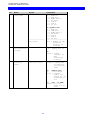
No.
10
11
Name
Page Format
Paper Path
Syntax
%Y10,<n1>[,n2]%
Parameters
n1
0 = Portrait
1 = Landscape
*2 = COR
82 = COR regardless of
Print Quality
n2
1 = Tractor
2 = Tray 1
3 = Drawer 2
4 = Manual feeder
5 = Envelope feeder
6 = Tray 3
1 = Tractor
*2 = Tray 1
3 = Drawer 2
4 = Manual feeder
5 = Envelope feeder
6 = Tray 3
%Y11,<n1>%
-34-
Programming via Shareport
ida FS 250, Operator's Guide
No.
12
Name
Paper Size
Syntax
%Y12,
<n1>[,n2,n3]%
NOTE:Factory
default depends
on DIP switch
settings
Parameters
n1 (Physical paper
size)
*1 = A4
2 = Legal
3 = Letter
4 = Executive
5 = Letter
(Monarch)
6 = Business
7 = International
DL
8 = International
C5
10 = A3
11 = Ledger
99 = Use system SPPS or
SHF/SVS values
n2 (Tray)
1 = Tractor
2
3
4
5
6
=
=
=
=
=
Tray 1
Tray 2
Manual feeder
Envelope feeder
Tray 3
n3 (Validation paper
size)
*1 = A4
2 = Legal
3 = Letter
4 = Executive
5 = Letter(Monarch)
6 = Business
7 = Internat.
8 = Internat.C5
10 = A3
11 = Ledger
15 = Comm 9 Envel.
16 = B5 Envelope
-35-
Programming via Shareport
ida FS 250, Operator's Guide
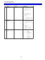
No.
15
Name
Baud Rate for
RS232 interface
Syntax
%Y15,<n1>%
16
Number of Data
Bits
%Y16,<n1>%
17
Parity
%Y17,<n1>%
18
Number of Stop
Bits
%Y18,<n1>%
19
Duplex
Printing
%Y19,<n1>%
21
Horizontal
Compression &
Vertical
scaling
%Y21,<n1>[,n2,n3]%
Parameters
n1
0 = 300 baud
1 = 600 baud
2 = 1200 baud
3 = 2400 baud
4 = 4800 baud
*5 = 9600 baud
6 = 19200 baud
n1
7 = 7 bits
*8 = 8 bits
n1
0 = odd parity
*1 = no parity
2 = even parity
n1
*1 = 1 stop bit
2 = 2 stop bits
*0 = Simplex
1 = Long-edge duplex
2 = Short-edge duplex
n1
0 = Compression
*1 = No compression
n2
1 =
2 =
3 =
4 =
5 =
6 =
22
24
Printer driver
selection
Interface
Selection
Tractor - Tray 1
Drawer 1
Tray 2
Manual feeder
Envelope feeder
Tray 3
n3
1-255 = Vertical
scaling in %
*100
2 = HP PCL 4
*4 = HP PCL 5
n1
*0 = Port 0
(Centronics out or
Serial in)
1 = Port 1
(Serial out)
%Y22<n1>%
%Y24<n1>%
-36-
Programming via Shareport
ida FS 250, Operator's Guide
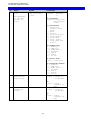
No.
36
37
48
Name
Suppress IBM
control codes
IBM Printer
Emulation
Select
Permanent Escape Character
Selection
Syntax
%Y36<n1>%
Parameters
*0 = Respect codes
1 = Suppress codes
n1 device address
*3812
5224
5225
5256
4234
4245
(IPDS)
%Y37,n1,<n2>%
n2 secondary address
0-6
'<n1>'
= value can be
entered by means
of an apostrophe
notation
or:
= HEX value of the
character selected
from the table
%Y48,'<n1>'%
or:
%Y48,<n1>%
-37-
Programming via Shareport
ida FS 250, Operator's Guide
No.
51
Name
User-Defined
String(s) at
Power-Up
Syntax
%Y51,<n1>%
59
Bar Code Type
Definition
%Y59,<n1>,<n2>,
<n3>,<n4>[,n5]%
Parameters
0-7 = One or more
strings stated
in the form:
(n1),(n2)
,....(nx) in
ascending order
The strings
must be predefined in FSL
61
n1
Numeric value from
1-8 specifying the
bar code no.
n2
22-39 = Bar code type
n3
Bar code height in
inches with values
from 1-255
n4
Horizontal expansion
with values from 1-16
61
Setup for User
Strings
%Y61,<n1>,<n2>%
62
Setup for IBM
defined
strings
%Y62,n,<string>%
n5
Optional GFID number
n1
0-99 = User Strings
supported
n2
00-FF = Hexadecimal
string data
n
string id number (0255)
string
string contents in
HEX and/or char. with
apostrophe notation
For details on
function, please see
the 5250 Programmer's
Guide, Doc. No.:
D62079
-38-
Programming via Shareport
ida FS 250, Operator's Guide
No.
73
Name
Select Translate Table
Syntax
%Y73,<n1>[,n2]%
----------------%Y73,<n1>%
74
75
Printer Symbol
Set Definition
Strings
User Defined
Translate
Table
%Y74,<n1>,<n2>%
%Y75,
<n1>,<n2>,<n3>%
Parameters
n1 (Translate Table)
*1 = Roman-8
2 = IBM PC-8
3 = ECMA Latin 1
5 = US ASCII
6 = OCR A
7 = OCR B
8 = PC 850
n2 (Symbol Set)
*1 = Roman-8
2 = IBM PC-8
3 = ECMA Latin 1
5 = US ASCII
6 = OCR A
7 = OCR B
8 = PC 850
--------------------*1-9 = Number of the
translate
table to be
selected
n1
1-8 = Symbol set no.
n2
00-FF = String
contents in
HEX
apostrophe
notation
n1 (EBCDIC)
40-FF = corresponds
to position
in translate
table
n2
(Symbol Set)
00
= no change
01-08 = printer
symbol set
string no. as
specified in
Y74
n3
(ISO - in HEX)
00-FF = up to 16
bytes can be
used
-39-
Programming via Shareport
ida FS 250, Operator's Guide
No.
88
Name
Physical
Margins
Syntax
%Y88,<n1>,<n2>
[,n3]%
Parameters
n1
0 - +/-32000
= Horizontal margin
compensation in
1/1440"
n2
0 - +/-32000
= Vertical margin
compensation in
1/1440"
89
90
Physical
Margin
Compensation
User Escape
String Definition
%Y89,<n1>[,n2]%
%Y90,<n1>,<n2>%
n3
0-2 = Orientation as
defined in FSL
10
n1
*0 = No compensation
1 = Compensation as
defined in FSL
88
n2
1 =
2 =
3 =
4 =
5 =
6 =
n1
Tractor
Tray 1
Tray 2
Manual feeder
Envelope feeder
Tray 3
0 = Erase
strings
01-FF = Hexadecimal
user Esc.
string no.
n2
= String
contents in
apostrophe
notation.
-40-
Programming via Shareport
ida FS 250, Operator's Guide
No.
91
Name
Font Definition
Syntax
%Y90,<n1>,<n2>,
<n3>,<n4>,<n5>
[,n6]%
See Appendix
D. for more
details on
fonts
Parameters
n1 (IBM GFID)
1-65535 = IBM GFID
no.
n2 (Typeface)
0-255 = Pre-programmed typeface
value
n3 (Attribute)
0 = Remove all
current attributes
1 = Bold
2 = Italic
3 = Bold and Italic
4 = Proportional
5 = Prop. Bold
6 = Prop. Italic
7 = Prop. Bold and
Italic
n4
*1
2
3
5
6
7
8
(Symbol Set)
= Roman-8
= IBM PC-8
= ECMA Latin 1
= US ASCII
= OCR A
= OCR B
= PC 850
n5 (Point Size)
1-255 = Point size
92
93
Font Point
Size Definition String
Font Attribute
Definition
String
%Y92,<n1>,<n2>%
%Y93,<n1>,<n2>%
n6 (Translate Table)
*1 = Roman-8
2 = IBM PC-8
3 = ECMA Latin 1
5 = US ASCII
6 = OCR A
7 = OCR B
8 = PC 850
n1
10-255 = String no
in decimal
n2
00-FF = String
contents in
HEX
n1
10-255 = String no
in decimal
n2
00-FF = String
contents in
HEX
-41-
Programming via Shareport
ida FS 250, Operator's Guide
No.
94
96
97
Name
Font Typeface
Definition
String
Font Change
Simulation
See Appendix D
for details on
scalable fonts
GFID/Font
Selection
Syntax
%Y93,<n1>,<n2>%
Parameters
n1
10-255 = String no
in decimal
%Y96,<n1>%
n2
00-FF = String
contents in
HEX
1-65535 = GFID no.
%Y97,
n1>,<n2>:<n3>%
n1
1-65535 = GFID No.
n2
<string> = String
for 0°
rotation
98
Automatic Page
Orientation
(APO)
%Y98,<n1>[,n2]%
n3
<string> = String
for 90°
rotation
n1
*0 = Activate APO
1 = Deactivate APO
n2
1 = Tractor
100
Port Sharing
Option
%Y100,<n1>[,n2]%
2 = Tray 1
3 = Tray 2
4 = Manual feeder
5 = Envelope feeder
6 = Tray 3
n1
0-255 = Timeout in
seconds
*20
n2
00-FF = Optional
string in
HEX to be
sent to
printer
before
transmission
of data when
printer is
selected by
sharing unit
-42-
Programming via Shareport
ida FS 250, Operator's Guide
No.
119
Name
AutoConfigura
tion select
Syntax
%Y119,<n1>%
120
Settings
printout at
power up
%Y120,n1%
249
Enter Engineering Mode
%Y249,n1%
T
Initiate Tests
%T#
X
Save/
Overwrite
Settings
%X#
S
Send User
String
Send User
String
Bar Code
Printing
%Sn%
Z
W
Parameters
n1
*0 = Disable Autoconfiguration
2 = Autoconfiguration
via PJL
n1
*0= disable settings
printout at power
up
1= enable settings
printout at power
up
n1
password
(contact your local idata distributor)
1= On-line hex dump
3= ASCII hex dump
4= settings printout
5= printout translate
table
6= cancel ASCII hex
dump
1= store RAM in
EEPROM
3= factory default to
RAM
4= restore settings
to power up
defaults
1-99 user strings may
be sent
1-8 user strings can
be sent
n1
1-8 Bar code
definition as
defined in Y59.
%Zn
%W,<n1>,<n2>%
n2
a-z,A_Z,0-9
Number or
alphanumeric
data to be
printed in bar
code. Data must
not exceed one
line
P
Program Flash
Prom
%P2,area_id,
intel_hex_data%
-43-
This function is only
available in
engineering mode
(Y249)
Programming via Shareport
ida FS 250, Operator's Guide
9. Programming via Shareport
In order to ease customization of the ida FS 250, FSL parameters for twinax
input can be programmed directly via the interface's Centronics or serial
(RS-232) port using the Engineering Function Y249.
The Engineering Function enables the system to detect whether FSL
sequences on shareport are intended for twinax FSL input or for shareport
setup and will direct the sequences received to the twinax FSL interpreter.
The sequence works as a switch for FSL sequences. The defined Escape
Character will also be translated and defined as Escape Character for the
twinax FSL module. Function Y 249 is automatically deactivated after
timeout on the shareport (i.e. settings defined in Y249 cannot be saved in
the NVRAM).
The setup sequence must only contain ASCII characters. Apostrophe
notation can be used if characters are included in the US ASCII 7 bit
character set. All other data must be in HEX notation.
All functions which are accessible from the twinax input can be used via
Centronics/RS-232 setup.
Activating the Y249 Engineering Function
Before the Engineering Function can be activated, an Escape character must
be defined:
&&??<character>
The sequence "&&??%" will define "%" as the ESC Character.
-44-
Programming via Shareport
ida FS 250, Operator's Guide
If you have defined % as Escape Character, you activate the engi neering
function by typing:
%Y249,n%
n = password. As this is sensitive information, system operators can contact
point of purchse for password details.
Deactivating the Y249 Engineering Function
The function will be deactivated automatically after timeout on the share port
(timeout is defined in Y100 Port Sharing Option). See also the chapter:
Specifying Share Timeout and String.
Limitations when Y249 is active
Escape sequences must be in HEX
Unprintable characters (i.e. the escape character) must be defined in HEX
notation if they are to be part of the setup print job. Only the FSL sequences
are allowed.
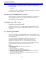
9.1 Updating firmware
The ida FS 250 firmware (complete firmware) may be updated either via the
twinax line or via centronics input port. For further in formation please contact
your i-data distributor.
If errors are detected, the downloading will be terminated and an error
message will be printed if possible. If serious errors occur during
programming, the firmware has to be downloaded via the share port.
The downloading of firmware is considered complete if no data is received
within 30 seconds. The interface will then make a soft re set.
NOTE:
In case of damaged FLASH PROM, try the following procedure:
Boot Download of firmware:
1. Turn the power off
2. Place the rotary switch in the “B” position
3. Turn the power on and note that the READY LED is lit
4. Download the boot firmware (Syntax: “Copy 140.xxx.1 /b”)
5. Download the new firmware. When download is completed and the FLASH PROM is
programmed, the LED will start flashing
6. Turn off the power and set the rotary switch in a position different from “A”, “B” or “T”
before turning on the power again.
-45-
Error Messages
ida FS 250, Operator's Guide
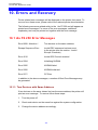
10. Errors and Recovery
Printer-related error messages will be displayed on the printer front panel. To
recover from these errors, please refer to the relevant printer documentation.
The following errors are related solely to the ida FS 250 and will appear as
printed error messages. For some of the error messages, additional
explanatory text may be printed out together with the error message.
10.1 ida FS 250 Error Messages
Error 8008 - Attention !
Two devices on the same address
Escape Sequence Error
Invalid ESC sequence has been sent
to the printer (see the section: Invalid
Escape Character)
Error 4510
Invalid SCS Control received
Error 5004
Initializing NVRAM
Error 5005
NVRAM failed
Error 5006
NVRAM initialized
Error 50??
CP Error
In addition to the above messages, a number of Boot Error Messages may
be generated.
10.1.1. Two Devices with Same Address
If two devices on the same twinax line has the same address, the printer will
print an error message. To recover follow these steps:
1. Turn the power off
2. Check each device on the same line against the system configuration.
3. Change the device address accordingly.
-46-
Appendix Section
ida FS 250, Operator's Guide
Appendix A: Use of ida FS 250 Serial Port
The following connections are available in the serial plug:
pin 1:
pin 2:
pin 3:
pin 4:
pin 5:
pin 6:
pin 7:
pin 8:
pin 9:
N.C.
RX data
TX data
DTR
GND (signal)
DSR (busy)
RTS (always high)
N.C.
N.C.
-47-
Appendix Section
ida FS 250, Operator's Guide
Appendix B: Test Printout
ida FS 250
Firmware version: S20 140.010/00970005
i-data international a-s
Vadstrupvej 35-43
2880 Bagsvaerd, Denmark
Phone: +45 44366000
Fax: +45 44366111
Boot id: 80023102 HW id:
Current escape code = 00 in hexadecimal as Character = ' '
Dipswitch: National character set = Multinational
Line Set Up: Addr. 0 3812 model 1.
4 *IPDS
Function 2:
Default LPI 6
Function 3:
Default CPI 10
Function 8:
Default codepage Multinational
Function 10: Default orientation = COR
Function 11: Default paperpath Drawer 1 Destination 2
Function 12: Papersize A4
Function 15: Baud rate: 9600
Function 16: Databits: 8
Function 17: Parity: None
Function 18: Stopbits: 1
Function 21: Horizontal compression = OffLine spacing 100%
Function 22: Print driver: PCL 5
Function 24: Output Source: 0
Function 36: Suppress SCS Controls: 0
Function 48: Permanent escape code: None
Function 51: User strings at power on: None
Function 59: Barcode definitions: None
Function 61: User strings: None
Function 62: Setup strings: None
Function 73: Translate table: 1 ROMAN 8
Function 74: Symbol set def.: None
Function 88: Physical margins: -288, -480 -288, -480- 288, -480
Function 89: Physical margin comp. = Off
Function 90: User Esc. strings: None
Function 91: User defined font translation table: None
Function 92: Point size strings: None
Function 93: Attribute strings: None
Function 94: Typeface strings: None
Function 97: User GFID/font selection
Function 98: Orientation select = Automatic
Function 100: IBM mode definition: Timeout 20 Sec.
Centronics input definition: Timeout 20 Sec.
RS232 input definition: Timeout 20 Sec.
Function 119: Autoconfiguration = 0
Function 120: Settings Printout at Power up = Off
Free bytes:
1851
Substitute character in hexadecimal = 60
Left margin in 1/1440"
=
0
Indent margin in 1/1440" =
0
Right margin in 1/1440" =
19008
Paper width in 1/1440"
=
19008
Paper depth in 1/1440"
=
15840
Top margin in 1/1440"
=
174
Line distance in 1/1440 =
240
Maximum print line
=
66
-48-
Appendix Section
ida FS 250, Operator's Guide
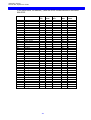
Appendix C: Default GFID Table
The factory default GFID Table below lists all the predefined fonts which are
supplied with the interface GFIDs (GFIDs 1 - 399) 2.
Fonts with GFIDs above 400 (i.e. scalable fonts) are described in the section
Scalable Fonts below.
For further details on defining fonts, please see the section: Quick Reference
of Supported FSL Functions, Function Y91 and Y96.
If more details on these FSL functions are required , you are referred to the
Programmer's Guide (D62079).
In the following Default GFID Table, the Attribute, Symbol Set and Translate
Table figures will refer to the following:
ATTRIBUTE
0 = No attributes
1 = Bold
2 = Italic
3 = Bold and italic
4 = Proportional
5 = Proportional bold
6 = Proportional italic
7 = Proportional bold and italic
SYMBOL SET and TRANSLATE TABLE
1 = Roman 8
2 = IBM PC-8
3 = ECMA Latin 1
4 = Roman 8
5 = US ASCII
6 = OCR A
7 = OCR B
8 = PC 850
2If,
for reasons of backward compatibility, you wish to reestablish the fonts > 400 in the
default GFID table, please contact you i-data supplier.
-49-
Appendix Section
ida FS 250, Operator's Guide
In the table below, an asterisk (*) after the GFID number denotes a simulated
IBM GFID.
GFID
Font
Typeface
3*
OCR B
0
11*
Courier
3
12*
Prestige
8
18*
Courier
3
19*
OCR A
0
38*
Presentation
11
39*
Letter Gothic
6
40*
Letter Gothic
6
46*
Courier
3
51
Courier
3
52
Courier
3
53
Courier
3
60
Letter Gothic
6
66*
Letter Gothic
6
68*
Letter Gothic
6
69*
Letter Gothic
6
80
Prestige
8
85
Courier
3
86*
Prestige
8
87*
Letter Gothic
6
91*
Letter Gothic Italic
6
95*
Courier Italic
3
109*
Letter Gothic Italic
6
110*
Letter Gothic
6
111*
Prestige
8
112*
Prestige
8
115
Courier
3
116
Courier
3
117
Prestige
8
118
Prestige
8
119
Prestige
8
204*
Letter Gothic
6
221*
Prestige
8
223*
Courier
3
230*
Letter Gothic
6
252*
Line Printer
0
253
Line Printer
0
255
Letter Gothic
6
256
Prestige
8
Default GFID Table for GFIDs 1 - 399
-50-
Attribute
0
0
0
2
0
1
1
0
1
0
1
2
0
0
2
1
0
0
0
0
2
2
2
1
1
2
1
2
0
0
2
0
0
0
0
0
0
0
0
Symbol
Set
7
1
1
1
6
5
1
1
1
5
5
5
5
1
1
1
1
1
1
1
1
1
1
1
1
1
1
1
5
5
5
5
1
1
1
1
1
1
5
Point
Size
12
12
10
12
12
14
14
14
12
12
12
12
14
12
12
12
10
12
10
12
12
10
12
12
10
10
10
10
10
10
10
12
7
8
9
8.5
8.5
9.5
7
Translate
Table
7
0
1
1
6
5
1
1
1
5
5
5
5
1
1
1
0
1
1
1
1
1
1
1
1
1
1
1
5
5
5
5
1
1
1
1
0
1
5
Appendix Section
ida FS 250, Operator's Guide
Scalable Fonts
NOTE:
Only applies to printers running PCL Level .5
The ida FS 250 allows GFID access to all the scalable fonts found in the
printer. These GFIDs are in the range 400 - 65535.
Typeface, typeface attributes and point size have been linked together using
the system described below.
GFID Number = XXXYY
where XXX = point size
and
YY = typeface + attribute
Possible typeface values are:
Typeface
ID
0
4
10
14
20
24
30
34
40
44
50
54
60
PCL No.
Name of Typeface
5
4116
4
36
23
4297
17
4168
31
4197
16901
16602
52
Times Roman
Coronet
Helvetica / Swiss
Helvetica Compressed
Century Schoolbook
Mangold
Humanist / CG Optima
Antique Olive
ICT Avantgarde
Garamond Antique
Times New
Arial
Univers
Possible attribute values are:
Style
0
1
2
3
Strokeweight
Medium upright
Bold upright
Medium italic
Bold italic
-51-
Appendix Section
ida FS 250, Operator's Guide
%Y96,4815%
This is 48 point, Helvetica Compressed, bold upright
%Y96,1301%
This is 13 point, Times Roman, bold upright
Font examples
Other relationships between IBM GFID and printer typefaces/fonts can be
programmed using Function 91 or 97 (See Programmer's Guide for more
details on Function 97). GFIDs may be selected with the normal
procedure or using Function 96.
-52-
Appendix Section
ida FS 250, Operator's Guide
Appendix D: i-data Product Platform
Coax
ida LS 170
ida LS 270
ida FS 270
ida FS 270 PDS
ida PDS 270x MIO
ida PDS 270x Optra
Twinax
ida LS 150
ida LS 250
ida FS 250
ida FS 250 PDS
ida PDS 250x MIO
ida PDS 812-1x Optra
S/370 - 390
External
S/370 - 390
External
External
S/370 - 390
External
Internal
Internal
AS/400
External
AS/400
External
External
AS/400
External
Internal
Internal
SCS
For Centronics attached matrix printers
SCS + AFP
For Centronics attached laser printers
For PCL printers
IPDS
For PCL printers
For HP MIO printers with HP PCL4 or higher
For Lexmark Optra L, N, R and C series
SCS
For Centronics attached matrix printers
SCS/DCA
For Centronics attached laser printers
For PCL printers
IPDS
For PCL printers
For HP MIO printers with HP PCL4 or higher
For Lexmark Optra L, N, R and C series
-53-
Appendix Section
ida FS 250, Operator's Guide
Token Ring
ida PS 03 TR
ida PrintServer 03 IOP TR
ida PrintServer 03 MIO TR
ida PS 03 NP TR
ida PS 23 TR 270
ida PrintServer 23 IOP TR 270
ida PrintServer 23 MIO TR 270
ida PS 23 NP TR 270
ida PS 23 TR 250
ida PrintServer 23 IOP TR 250
ida PrintServer 23 MIO TR 250
ida PS 23 NP TR 250
ida PS 13 TR
ida PrintServer 13 IOP TR
ida PrintServer 13 MIO TR
ida PS 13 NP TR
Ethernet
ida PS 04 ETH
ida PrintServer 04 IOP ETH
ida PrintServer 04 MIO ETH
ida PS 04 NP ETH
ida PS 24 ETH 270
ida PrintServer 24 IOP ETH 270
ida PrintServer 24 MIO ETH 270
ida PS 24 NP ETH 270
ida PS 24 ETH 250
ida PrintServer 24 IOP ETH 250
ida PrintServer 24 MIO ETH 250
ida PS 24 NP ETH 250
ida PS 14 ETH
ida PrintServer 14 IOP ETH
ida PrintServer 14 MIO ETH
ida PS 14 NP ETH
SOFTWARE
ida HPR
ida PSS MVS
ida PSS VM
ida RPPC NLM
ida RPPC AIX
ida RPPC HP UX
ida RPPC Windows NT
ida RPPC Sinix
S/370 - 390
External
Internal
Internal
Internal
S/370 - 390
External
Internal
Internal
Internal
AS/400
External
Internal
Internal
Internal
AS/400 & S/370-390
External
Internal
Internal
Internal
S/370 - 390
External
Internal
Internal
Internal
S/370 - 390
External
Internal
Internal
Internal
AS/400
External
Internal
Internal
Internal
AS/400 & S/370-390
External
Internal
Internal
Internal
AFP
For Centronics attached laser and matrix printers
For Lexmark Optra L, R, N and C series
For HP MIO printers with HP PCL4 or higher
For IBM Network Printer series
SCS + AFP
For Centronics attached laser and matrix printers
For Lexmark Optra L, N, R and C series
For HP MIO printers with HP PCL4 or higher
For HP MIO printers with HP PCL4 or higher
SCS/DCA
For Centronics attached laser and matrix printers
For Lexmark Optra L, N, R and C series
For HP MIO printers with HP PCL4 or higher
For HP MIO printers with HP PCL4 or higher
IPDS
For Centronics attached PCL printers
For Lexmark Optra L, N, R and C series
For HP MIO printers with HP PCL4 or higher
For IBM Network Printer series
AFP
For Centronics attached laser and matrix printers
For Lexmark Optra L, N, R and C series
For HP MIO printers with HP PCL4 or higher
For IBM Network Printer series
SCS + AFP
For Centronics attached laser and matrix printers
For Lexmark Optra L, N, R and C series
For HP MIO printers with HP PCL4 or higher
For IBM Network Printer series
SCS/DCA
For Centronics attached laser and matrix printers
For Lexmark Optra L, N, R and C series
For HP MIO printers with HP PCL4 or higher
For IBM Network Printer series
IPDS
For Centronics attached PCL printers
For Lexmark Optra L, N, R and C series
For HP MIO printers with HP PCL4 or higher
For IBM Network Printer series
S/370 - S/390
Host software
S/370 - S/390
Host software
Host software
Server software
Server software
Server software
Server software
Server software
PRINT REDIRECTION
For PCL or PostScript printers
AFP
For PCL or PostScript printers
For PCL or PostScript printers
For local or remote PCL printers
For local or remote PCL printers
For local or remote PCL printers
For local or remote PCL printers
For local or remote PCL printers
-54-
Index
ida FS 250, Operator's Guide
Programmer's Guide, 28
Index
—Q—
Quick FSL Reference Guide, 32
—S—
—C—
Scalable Fonts (Typographic), 51
Shareport
Connections
A/B Switch, 13
Address Switch, 13
Parallel In, 12
Parallel Out, 12
Serial Port (Out), 47
Serila (In/Out), 12
Twinax Connector, 13
Activating Y249, 44
Deactivating Y249, 45
Programming via, 44
—T—
Testing
Control units, 9
Via address switch, 20
via function T, 20
—D—
Timeout, 21
Specifying, 24
Default FGID Table, 49
—E—
Emulation, 13
Via address switch, 14
Via the line, 15
error messages, 46
ESC
Invalid, 29
ESC Character
Define temporary, 29
Defining, 24
Remove, 29
Escape Character, 28
Define temporary, 29
—F—
Firmware updating, 45
Front panel, 22
FSL 100
Defining Timeout, 24
FSL functions, 30
Function Selection via the Line
Syntax, 29
—I—
i-data Product Platforms, 54
Indicator LEDs
PAR, 22
READY, 23
SER, 23
SYNC, 22
Installation
Pre-inst. requirements
EU/US settings, 11
National language, 10
IRQ Handling, 27
—P—
Pre-installation requirements, 10
Printer sharing, 21
Product features, 8
-55-
Reader's Comments
ida FS 250, Operator's Guide
READER'S COMMENTS
This manual is part of a library that serves as a reference source for programmers
and operators of i -data equipment. This form may be used to communicate your view
about this publication. Your in terest is appreciated.
Comments may be written in your own language, use of English is not required.
Documentation
i-data international a-s
Vadstrupvej 35-43
DK-2880 Bagsvaerd
Denmark
or use our E-mail address at the Internet:
i-data
i-data.com
-56-