1
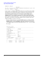
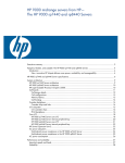
AB290A PCI-X 2-Port U320 SCSI and 2-Port Gigabit Ethernet Combination Card Installation Guide For mpt Driver Versions B.11.11.02 and B.11.23.01 and For iether Driver Versions B.11.11.07 and B.11.23.05 HP 9000 and HP Integrity Systems Manufacturing Part Number : AB290-90001 E0405 Printed in the U.S.A. © Copyright 2005 Hewlett-Packard Development Company L.P. Legal Notices The information in this document is subject to change without notice. Hewlett-Packard makes no warranty of any kind with regard to this manual, including, but not limited to, the implied warranties of merchantability and fitness for a particular purpose. Hewlett-Packard shall not be held liable for errors contained herein or direct, indirect, special, incidental or consequential damages in connection with the furnishing, performance, or use of this material. Warranty A copy of the specific warranty terms applicable to your Hewlett- Packard product and replacement parts can be obtained from your local Sales and Service Office. Restricted Rights Legend Use, duplication or disclosure by the U.S. Government is subject to restrictions as set forth in subparagraph (c) (1) (ii) of the Rights in Technical Data and Computer Software clause at DFARS 252.227-7013 for DOD agencies, and subparagraphs (c) (1) and (c) (2) of the Commercial Computer Software Restricted Rights clause at FAR 52.227-19 for other agencies. HEWLETT-PACKARD DEVELOPMENT COMPANY L.P. 20555 S.H. 249 Houston, Texas 77070 Use of this document and any supporting software media supplied for this pack is restricted to this product only. Additional copies of the programs may be made for security and back-up purposes only. Resale of the programs, in their present form or with alterations, is expressly prohibited. Trademark Notices UNIX is a registered trademark in the United States and other countries, licensed exclusively through The Open Group. Itanium, Itanium2, and Intel are registered trademarks of Intel Corp. HP Serviceguard and Superdome are registered trademarks of Hewlett-Packard Co. This Installation Guide has been translated to: http://www.docs.hp.com/ja/index.html 2 Hardware and Software Installation Procedure Step 1: Access the system card bay Hardware and Software Installation Procedure These instructions apply to AB290A PCI-X 2-Port U320 SCSI and 2-Port Gigabit Ethernet combination cards. For pre-requisite information such as system firmware requirements or card firmware requirements, please see the AB290A Combination Card Support Matrix on the web at http://docs.hp.com under “I/O Cards and Networking Software” and then under “Combination Cards.” If your combination card was factory installed (ordered on product option 0D1), the two software bundles required for this card --IEther-00 (for LAN) and scsiU320-00 (for SCSI) are already loaded onto your system’s hard drive.1 Adding in the card: HP-UX 11i v 1.0 If your system is HP-UX 11i v 1.0 based, you need to get the two driver bundles from the December 2004 version of HP-UX 11i v 1.0. You do not necessarily have to load the entire OE if you don’t want to. To add the product for 11i v 1.0: • You can either load the entire HP-UX 11i v 1.0 December 2004 OE from the distribution media and you will automatically get the correct LAN and SCSI driver bundles. or • You can just select and load the two driver bundles IEther-00 and scsiU320-00 required for this card. Adding in the card: HP-UX 11i v 2.0 of September 2004 or later • In order to use the AB290A combination cards with HP-UX 11i v 2.0 of September 2004, your system needs to be on that OE. • So, if your system does not have 11i v 2.0 of September 2004 (or later), you need to load the entire HP-UX 11i v 2.0 September 2004 (or later) OE from the distribution media, and you will automatically get the correct LAN and SCSI driver bundles. These AB290A combination cards can be added to your system or replaced without the need to shut down or reboot the system--a process called online addition and replacement (OLAR). The following instructions assume you are not performing online addition and replacement. Step 1: Access the system card bay • If the system is running, first, issue the sync command. Then, shut down the system by executing: shutdown -h. Respond “y” to the continue to shutdown prompt. • Wait for the system to shut down completely, and then power off the system by pressing the system off button. Ensure that the system is grounded. • Open the system to gain access to the PCI backplane. • Select an empty PCI or PCI-X slot and remove the slot cover. The card can operate in PCI as well as PCI-X mode. Some servers have “shared” slots. If you put this card in a shared slot that is shared with a slower card, both cards will then operate at the slower card’s speed. 1. If your combination card was factory installed (ordered on product option 0D1), you do not need to perform the hardware and software installation steps,. You still need to configure the card’s IP address and possibly set other parameters and options such as those mentioned in Table 2 on page 12 The Network Configuration worksheet. 3 Hardware and Software Installation Procedure Step 2: Install the card Step 2: Install the card • Check the latest support matrixes to see the systems that support this card, how many cards per system, and if any software updates are needed. There are support matrixes for both Gigabit Ethernet and SCSI available on the web at http://docs.hp.com under “I/O Cards and Networking Software.” • Observe the antistatic precautions. HP recommends wearing ESD straps when installing the card. • Record the serial number and MAC address located on the card for future reference. The MAC address labelled on the card refers to LAN port A. Add 1 to obtain the MAC address for LAN port B. • Grasp the card by its edges or faceplate with both hands, insert the card into the slot, and firmly but gently press the card in until it is fully seated. • Secure the card and reassemble the system. Step 3: Connect the card to the network • Attach two LAN cables to the card (Figure 1). For 1000Base-T, cabling must be Cat 5 UTP or better with RJ-45 connectors. The maximum cable length for 1000Base-T (Copper UTP) is 100 meters over Cat 5 or Cat 5E. • Attach the free end of a LAN cable to any unused port on the switch. Do the same for the other port. The LAN ports on the cards operate at 10 or 100 Mbit/s in either full- or half-duplex modes and at 1000 Mbit/s only in full-duplex mode. Set the ports on the card and on your switch according to the following table. Table 1 HP-UX 1000Base-T Supported Configurations HP-UX 1000Base-T Port Link Partner Resulting Speed AUTO AUTO Highest Common Speed (HP-UX supports 10/100/1000) AUTO 1000 FD fixed/manual 1000 Mbit/s FD 10 HD 10 HD (for example, a 10Base-T Hub) 10 Mbit/s HD 10 FD 10 FD 10 Mbit/s FD 100 HD 100 HD 100 Mbit/s HD 100 FD 100 FD 100 Mbit/s FD If you are using Jumbo Ethernet frames, ensure that: — all end stations on a given LAN1 have the same maximum transmission unit (MTU) setting; — intermediate stations such as switch ports in your LAN have an MTU equal to or greater than the end station’s MTU. 1. In the Jumbo Frames discussion, “LAN” means that the end stations do not have any routers or layer 3 switches in between them. 4 Hardware and Software Installation Procedure Step 4: Connect the SCSI peripherals Step 4: Connect the SCSI peripherals You can connect as many as 15 other SCSI devices to each port on this card by chaining them together serially with shielded external SCSI cables. The maximum length of the SCSI bus is 12 meters when using LVD signalling and 6 meters when using SE. • Plug the 68-pin very high density cable interconnect (VHDCI) connector on the shielded external cable into SCSI port A or B. • Plug the 68-pin connector on the other end of the shielded external SCSI cable into the SCSI connector on your external SCSI device. SCSI Bus Termination The pieces of equipment on the ends of a SCSI bus normally have terminators. Remove or disable termination on all other SCSI devices or initiators in the middle of the bus. This card’s SCSI ports have automatic termination when shipped from the factory--no physical terminators are required on unused ports of the card. Please be aware of the following conditions: — Connect only external SCSI devices to this SCSI card. Terminate the last external device on the SCSI bus, and disable the termination on all other devices. Termination on this SCSI card is automatically enabled in this case (if the jumper is off). — Low-voltage differential peripheral devices are normally terminated with external terminators but are sometimes set with jumpers or a switch on the peripheral. Refer to the device manual to identify terminator settings and how to change them. Step 5: Power Up the system • Determine the SCSI ID required for each device on the SCSI bus. • Power up the system. • Record the IDs of the SCSI ports on this card. Setting SCSI IDs Offline For PA-RISC based systems, you can use the Boot Console Handler (BCH) menus to set SCSI IDs offline according to the instructions in the manual HP A7173A PCI-X Dual Channel Ultra320 SCSI Host Bus Adapter Support Guide available at http://docs.hp.com. For Itanium based systems, use EFI to set the SCSI IDs offline. See the HP A7173A PCI-X Dual Channel Ultra320 SCSI Host Bus Adapter Support Guide for details. Setting SCSI IDs Online For all supported systems (HP Integrity or HP 9000), you can use the mptconfig command to display and set SCSI IDs online . See the HP A7173A PCI-X Dual Channel Ultra320 SCSI Host Bus Adapter Support Guide for details. NOTE Peripheral device SCSI IDs are typically determined automatically by the storage enclosure, or they may be set manually by a switch on the storage enclosure. Refer to the peripheral device documentation, to determine how the SCSI ID of each peripheral device is set, and how to change it. 5 Hardware and Software Installation Procedure Step 6: Prepare to install the software IMPORTANT You must not have duplicate SCSI IDs on a SCSI bus; the system may hang or crash if you have duplicate SCSI IDs on the same bus. Setting SCSI IDs You must set each SCSI device and its corresponding port on the SCSI card to a separate SCSI ID, 0 through 15 for a 16-bit SCSI. SCSI ID 7 is the preset host adapter setting, giving it the highest priority on the SCSI bus. To change this default to a different SCSI address for high availability (HA) systems, you must use the Boot Code Handler or BCH. You must invoke the appropriate commands in the SCSI section of the BCH and change the address electronically to whatever is required for the HA configuration being used. Peripheral device SCSI IDs are usually set with jumpers or a switch on the peripheral. Refer to the peripheral manufacturer’s instructions to determine the ID of each device and how to change it. You must have no duplication of SCSI IDs on a SCSI bus. • Upon power up, any error messages will appear on the terminal display or system console. You can also use the dmesg command to retrieve startup messages later. • Verify that the Ethernet LAN connector’s Link LED is on. • When the system is up, log in as root and verify that the card and its hardware path are displayed by executing the command: ioscan. Step 6: Prepare to install the software • Check that the /usr/bin, /usr/sbin, and /sbin directories are in your PATH using the command: echo $PATH • Check the HP-UX version by entering: uname -r # uname -r B.11.11 or B.11.23 The version must be B.11.11 for 11i v 1.0 or B.11.23 for 11i v 2.0. • Check the Release Notes for IEther-00 and scsiU320-00 to see if you need to install any appropriate patches for your system. Release Notes are available on the Web at http://docs.hp.com under I/O Cards and Networking Software. Step 7: Install the latest software. • Load the software media into the appropriate drive. — If you are adding the Gigabit Ethernet software bundle (IEther-00) for 11i v 1.0, you can get the Gigabit Ethernet software bundle on the December 2004 (or later) OE distribution media. — If you are adding the Gigabit Ethernet software bundle (IEther-00) for 11i v 2.0, you must use the September 2004 (or later) OE distribution media. • Run the swinstall program to install the software using the command: swinstall. • Change the host name after “Source Host Name,” if necessary. 6 Hardware and Software Installation Procedure Step 8: Configure the card using SAM • Click the Source Depot Path to identify the registered depot for the appropriate source depot path and activate the OK button to return to the Software Selection Window. • Highlight the 1000Base-T software IEther-00 (for cards such as AB290A). • Choose Mark for Install from the “Actions” menu to choose the product to be installed. • Choose Install from the “Actions” menu to begin product installation and open the Install Analysis Window. • Activate the OK button in the Install Analysis Window when the Status field displays a “Ready” message. • Activate the YES button at the Confirmation Window to confirm that you want to install the software. swinstall loads the fileset, runs the control scripts for the filesets, and builds the kernel. This should take about 3 to 5 minutes. When the status field indicates Ready, click Done. A Note Window then opens. Click the OK button to reboot the system. • If you are adding the SCSI driver (scsiU320-00) for 11i v 1.0, you can find the SCSI driver on the December 2004 (or later) OE distribution media. If you are adding the SCSI driver (scsiU320-00) for 11i v 2.0, you must use the September 2004 (or later) OE distribution media. Just repeat Step 7 to load it. Step 8: Configure the card using SAM • Log in as root and verify that the card and its hardware path are displayed by entering: ioscan. • Run the System Administration Manager by entering: sam. • Double-click Networking and Communications. • Double-click Network Interface Cards. • Highlight the AB290A combination SCSI/Gigabit Ethernet card and choose Configure from the “Actions” menu. • Fill in the form according to the instructions using the “Network card Configuration Worksheet” in this document. • Click the OK button to activate the card and then select exit from the “File” menu until you exit SAM. Step 9: Verify the SCSI installation After installing the scsiU320-00 software bundle containing the mpt driver, installing the AB290A adapter, and attaching the peripheral devices, verify that all of the components are working by following these steps: • To verify that the mpt driver appears for each installed card, enter: ioscan -fnkd mpt The ioscan output will be similar to the following example: # ioscan -fnkd mpt Class I H/W Path Driver S/W State H/W Type Description ================================================ ext_bus 6 1/0/2/0/0 mpt CLAIMED INTERFACE HP AB290A PCI-X 2port U320 SCSI/2port 1000Base-T Adapter /dev/mpt6 ext_bus 7 1/0/2/0/1 mpt CLAIMED INTERFACE HP AB290A PCI-X 2port U320 SCSI/2port 1000Base-T Adapter /dev/mpt7 ext_bus 8 1/0/4/0/0 mpt CLAIMED INTERFACE HP AB290A PCI-X 2port U320 SCSI/2port 7 Hardware and Software Installation Procedure Step 9: Verify the SCSI installation 1000Base-T Adapter /dev/mpt8 ext_bus 9 1/0/4/0/1 mpt CLAIMED INTERFACE HP AB290A PCI-X 2port U320 SCSI/2port 1000Base-T Adapter /dev/mpt9 In this example, two AB290A adapters are installed on the system. The fourth and fifth columns in the ioscan output indicate that the adapters have been claimed by the mpt driver. The third column shows the hardware path of the slot in which the card is installed. This path will be different for each installed card. The AB290A adapter supports two PCI devices or functions (one per channel). Two lines are listed for each AB290A adapter, —one for channel A (denoted by a 0 as the last digit in the hardware path), and one for channel B (denoted by a 1 as the last digit in the hardware path). The device file for each channel of each installed adapter is in the second line of the ioscan output, for example: /dev/mpt6 or /dev/mpt7. — For more detailed information on installed AB290A adapter(s), including the SCSI parameter settings as well as verification of devices that have been connected to the AB290A adapter(s), issue the mptconfig <dev file> command for each channel of each AB290A adapter. Use the device files displayed in the ioscan -fnkd mpt output. For example: # mptconfig /dev/mpt8 Scan For Devices ... ---- ADAPTER INFORMATION ----------------------------------------------------Device File : /dev/mpt8 Hardware Path : 1/0/4/0/0 ---- BUS PARAMETERS ---------------------------------------------------------Initiator SCSI ID : 5 SCSI Bus Rate : Ultra320 SCSI Bus Width : Wide ---- CHANNEL CAPABILITIES ---------------------------------------------------Req/Ack Offset : 127 Bus Mode : LVD Quick Arbitration Selection : Enabled DT Clocking : Enabled Packetized : Enabled ---- TARGET PARAMETERS ------------------------------------------------------Target Description Firmware In Use In Use Id Version Rate Width -----------------------------------------------------------------------------0 ST318453LC HPC3 Ultra320 Wide 2 ST373453LC HPC3 Ultra320 Wide 4 ST373453LC HPC4 Ultra320 Wide 8 Hardware and Software Installation Procedure Step 10: Verify the LAN installation -----------------------------------------------------------------------------# NOTE When the system boots after installation, the insf command creates the proper device files for the “ctl” interfaces (which would include the AB290A adapter) as well as the SCSI devices attached to the AB290A adapter. Sometimes, however, the insf command does not create all of the device files that are needed. For example, this happens when you attach SCSI disks to the adapter after the system boots, but the adapter is already installed in the system. If you see a SCSI device listed in the ioscan output, but there is no device file in the second line of the ioscan output for that device, the device file is missing. To solve this problem, issue the insf -e command, which will create all of the device files. For more information about the ioscan command, see the ioscan(1M) man page. For more information about the insf command, see the insf (1M) man page. Refer to your system documentation for information about verifying system operation. Step 10: Verify the LAN installation • Verify that the LAN connector’s Link LED is steadily on (this means the card and driver are installed successfully). • Obtain the PPA number and the station address of each card by using the lanscan command. • To verify link-level connectivity with a remote system, enter: $ linkloop -i PPA_number remote_station_address Note: when you use linkloop, ensure that the remote system is on the same subnet and is an HP-UX-based system. • To verify IP-level connectivity with a remote system, enter: $ping Remote_IP_Address and netstat -in When you use netstat -in, the output values Ipkts and Opkts should be incrementing. • Installation is complete when you have successfully run linkloop, ping, and netstat. To configure remote systems, see the Ethernet Support Guide available on the web at http://docs.hp.com. Do this step only if remote systems have not been previously configured. • Optionally, if you want to verify that the iether driver appears for each installed card, enter: ioscan -fknClan The ioscan output for each port would look something like the following: Class I H/W Path Driver S/W State H/W Type Description lan 3 1/10/0/1 iether CLAIMED INTERFACE HPAB290A PCI-X 2port U320 SCSI/2port 1000Base-T 9 Hardware and Software Installation Procedure Optional Step: Configure Jumbo Frames Size (Jumbo frames are supported only at 1000 Mbit/s) Adapter The last two digits of the hardware path (third column) reflect the path of each port. Optional Step: Configure Jumbo Frames Size (Jumbo frames are supported only at 1000 Mbit/s) • Jumbo frames for the iether driver on HP-UX 11i v 1.0 and on11i v 2.0 of September 2004 (or later) have an mtu_size in the range from 1501 to 9000 bytes. If you are using Jumbo Ethernet frames, ensure that: — all end stations on a given LAN1 have the same maximum transmission unit (MTU) setting; — intermediate stations such as switch ports in your LAN have an MTU equal to or greater than the end station’s MTU. • Obtain the PPA number of the card by entering lanscan. • Choose one of two configuration methods that will permanently save your configuration. — use the GUI-based system admin manager (SAM). To use SAM, type sam at the HP-UX system prompt; then double-click Networking and Communications, and then Advanced Configuration--see Ethernet Support Guide for details, and then do the steps for verifying the MTU size; or edit the following configuration file using an editor such as “vi”: /etc/rc.config.d/hpietherconf. Set the mtusize by editing HP_IETHER_MTU[0]=mtusize, and insert the proper interface name: HP_IETHER_MTU[i]=HP_IETHER_INTERFACE_NAME. When the system reboots, the interface will be configured for jumbo frame operation. • Verify MTU change by entering netstat -rn. If MTU has not changed, enter the following commands: $ifconfig lan PPA_number unplumb $ifconfig lan PPA_number ip_address netmask netmask up • To check (or verify) the current Ethernet frame size, enter: $lanadmin -m PPA_number An alternative way to temporarily configure jumbo frame size is to enter: lanadmin -M mtu_size PPA_number. Using lanadmin is temporary because it will not preserve your settings across reboots. The PPA_number is the one we obtained from the output of lanscan. For using Jumbo Frames with the iether Gigabit Ethernet driver on HP-UX 11i v 1.0 or 11i v 2.0 of September 2004 (or later), set the mtu_size to a number from 1501 to 9000 (bytes). For Further Information For further information on the Gigabit Ethernet and SCSI as implemented in this card, please refer to http://docs.hp.com and then look under I/O Cards and Networking Software. This card’s information is primarily located under the subsection called “Combination Cards.” 1. In the Jumbo Frames discussion, “LAN” means that the end stations do not have any routers or layer 3 switches in between them. 10 Hardware and Software Installation Procedure For Further Information Maintenance and troubleshooting information about the drivers used in this product can be found in various documents on: http://docs.hp.com under “I/O Cards and Networking Software.” The iether Gigabit Ethernet driver used in this product is located in the Ethernet Support Guide. There is maintenance and troubleshooting information about the mpt SCSI driver used in this product in the SCSI Support Guide. The mpt driver is the same one used in the A7173A SCSI product and has the same features as the driver described in that product’s documentation. For further details on advanced features, see the HP A7173A PCI-X Dual Channel Ultra320 SCSI Host Bus Adapter Support Guide. There is also a Support Matrix for Gigabit Ethernet and a separate one for SCSI. 11 Hardware and Software Installation Procedure Network Configuration Worksheet Network Configuration Worksheet Fill out one worksheet for the networking data of each LAN port on the combination card you are installing. Table 2 Data Type Network Configuration Worksheet Required/ Optional Default How to Configure (see Note 1) Example Internet Address Required 0.0.0.0 SAM or ifconfig or edit /etc/rc.config.d/ netconf 196.6.20.2 Subnet mask Required if using subnetting Subnet mask not used SAM or ifconfig or edit /etc/rc.config.d/ netconf 255.255.248.0 Station address Built-in but can be optionally changed As shown on card SAM or edit /etc/rc.config.d/ hpietherconf or temporarily: lanadmin -A 0x0060b0c4012f Host name alias for this network interface (card) Required if the system is connected to more than 1 network None SAM or edit /etc/hosts host1 Link configuration Required Autonegotiating SAM or temporarily: lanadmin -X lanadmin -X auto_on ppa# (if already turned off) Link speed/duplex mode Required Autonegotiating Hub or switch (see Note 2) SAM or temporarily: lanadmin -X lanadmin -X 100fd ppa# MTU (Maximum Transmission Unit): Jumbo Frames Optional 1500 bytes SAM or edit /etc/rc.config.d/ hpietherconf or temporarily: lanadmin -M lanadmin -M 9000 ppa# (see Note 3 below) Receive flow control Optional On SAM or edit /etc/rc.config.d/ hpietherconf or temporarily: lanadmin -X lanadmin -X fctrl off Your System Note 1: To configure values permanently, edit the configuration files using SAM or an editor such as “vi”. Using lanadmin will not preserve your settings across reboots. Note 2: The speed configuration of the card can be 10, 100, or 1000Mbps and is determined by the speed setting of the hub or switch port to which the card is connected. The card automatically senses this speed. The Base-T ports only run at one speed at a time. To verify the speed selection, run lanadmin -x ppa#. 12 Hardware and Software Installation Procedure Network Configuration Worksheet Note 3: Following are the valid MTU sizes: • For normal frames using the iether driver on HP-UX 11i v 1.0, the MTU size is a number from 257 to 1500 bytes. On HP-UX 11i v 2.0, the MTU size for normal frames is a number from 1024 to 1500 bytes. • For jumbo frames using the iether driver on HP-UX 11i v 1.0 or HP-UX 11i v 2.0, the MTU size is a number from 1501 to 9000 bytes. Figure 1 AB290A PCI-X 2-Port U320 SCSI and 2-Port 1000Base-T Combination Card T A T A SCSI Termination enable and Activity LEDs CH A SCSI LVD/SE CH B SCSI LVD/SE 68-Pin VHDCI SCSI Connectors LAN B } LAN A Activity/Link LEDs Flashing = Data traffic Solid = Active link OFF = No link 1000Base-T Connectors (RJ-45) Speed LEDs Off = 10 Mbit/s Green = 100 Mbit/s Yellow = 1000 Mbit/s 13 Hardware and Software Installation Procedure Product Overview and Requirements Product Overview and Requirements The AB290A PCI-X Combination cards have the following features and requirements: • PCI-X 133 MHz capable card. It can operate at 32-bit or 64-bit modes and is supported in the following frequencies: PCI 66, PCI-X 66, and PCI-X 133. Best performance is achieved by putting the card in a “dual-rope” PCI-X 133 slot. To identify which slots are the dual rope slots in a particular system, please refer to the hardware users’ guide for each system. The AB290A card is not supported in PCI 33 bus mode. It operates in 3.3V slots only. • Requires either HP-UX 11i v 2.0 (64 bit) operating environment (OE) of September 2004 (or later) or the two software bundles, IEther-00 (for LAN) and scsiU320-00 (for SCSI), from the 11i v 1.0 of December 2004 (or later) software distribution. — For 11i v 2.0, your system needs to be on the September 2004 operating environment or later, so you need to load the entire OE. — For systems that are already running 11i v 1.0, you can either just load the required software driver bundles, or you can load the entire OE and you will automatically get the two drivers you need for this card. • The Gigabit Ethernet ports support use of Jumbo Frames. • Supports HP Serviceguard for the whole card and Auto-Port Aggregation (APA) for high availability of the 1000Base-T ports. • The Gigabit Ethernet ports support virtual LANs (VLANs). This feature is described in Using HP-UX VLANs on http://docs.hp.com. • Supports PCI-X online addition/replacement (OLA/R) on specified systems. For instructions on how to perform online addition and replacement (OLAR) for PA-RISC-based systems running HP-UX 11i v 1.0, see Configuring HP-UX For Peripherals. For instructions on performing OL* for Itanium-based systems and PA-RISC systems running HP-UX 11i v 2.0 of September 2004 or later, refer to the Interface Card OL* Support Guide. • Supports configuration through SAM or command line. • Online/Offline Diagnostics. • Ignite UX support. • Maximum data rate of 320 Mbytes/s over each SCSI channel. • Supports boot over the 1000Base-T and SCSI interfaces. • SCSI T10 Parallel Interface SPI-4 operates as two 16-bit wide, synchronous or asynchronous, low-voltage differential (LVD) or single ended (SE) interfaces. • Supports vPars. • The AB290A does not support any configuration where it is in the middle of the SCSI bus (using “Y” cables or simultaneous internal and external connections. • SCSI termination is enabled by default. HP only supports configurations where the termination is enabled. The termination Disabled LED will glow when termination is disabled (basically during unsupported configurations)-- for example, when the terminators on that bus have been disabled. The channel A termination disable LED will only glow if the jumper is installed across both posts. The channel B termination disable LED will glow if the jumper is installed or if cables are connected to both the internal and external channel B connectors (this is not a supported configuration). 14 Hardware and Software Installation Procedure Interoperability: Supported Systems Interoperability: Supported Systems Supported Systems The combination card is supported in the HP Integrity (Itanium or Itanium2-based) systems specified in Table 3. Table 3 Combination Card in HP Integrity Systems rx1600 and rx1620 rx2600 rx2620 rx4640 rx7620 HP Integrity Superdome IA 16-way, 32-way, 64-way,128-way, and 192-way rx8620 and rx8620 with Server Expansion unit The combination card is supported in the HP 9000 (PA-RISC processor-based) systems specified in Table 4. Table 4 Combination Card in HP 9000 Systemsa rp3410-2 rp3440-4 rp4440-8 rp7420-16 HP 9000 Superdome (in 3.3 volt slots; PA8800 or later processors) PA 16-way, 32-way, 64-way, 128-way, and 192-way rp8420-32 and rp8420 with Server Expansion unit a. The AB290A combination card is not supported on rp7410, rp8400, or on HP 9000 Superdomes that have 8600 or 8700 processors. 15 Card Physical and Environmental Specs and Regulatory Information Card Physical and Environmental Specifications Card Physical and Environmental Specs and Regulatory Information Card Physical and Environmental Specifications Following are the product physical and environmental specifications of the AB290A PCI-X 2-Port U320 SCSI and 2-Port Gigabit Ethernet Combination Card. Physical Specifications Form Factor PCI-X (2.3) PCI support 64-bit 3.3V only 133Mhz Height 10.8 cm (4.25 in) Depth 21.6 cm (8.5 in) Width 2 cm (0.7 in) Weight 0.18 kg (0.4 lb) kg Electrical Power consumption: 25 Watts Environmental Temperature Degrees F = (1.8 x Degrees C) + 32 Operating Temperature Range (Degrees Celsius) +5o C to 40o C Recommended Operating Temperature Range (Degrees Celsius) +10o C to 40o C Non-operating/ storage Temperature Range (Degrees Celsius) -40o C to 70o C Temperature Shock Immunity - Max Rate of Change 20 C/hr Non-operating/storage Humidity Range in %RH 90 Recommended Operating Humidity Range @ 22 Degrees Celsius in %RH 40 to 60 Heat Dissipation (in Watts) 17 Maximum kV (if less than 15 kV) with no loss of function 8 Maximum kV (if less than 25 kV) with no component damage 25 Operating Altitude 3,000 meters (9900) ft Non-operating Altitude 4,500 meters (14850 ft) 16 Card Physical and Environmental Specs and Regulatory Information FCC Statement (For U.S.A.) Electromagnetic Compatibility This document contains regulatory statements for the United States and the European community. FCC Statement (For U.S.A.) Federal Communications Commission Radio Frequency Interference Statement WARNING This device complies with Part 15 of the FCC rules. Operation is subject to the following two conditions: (1) This device may not cause harmful interference and (2) this device must accept any interference received, including interference that might cause undesired operation. This equipment has been tested and found to comply with the limits for a Class A digital device, pursuant to Part 15 of the FCC rules. These limits are designed to provide reasonable protection against harmful interference when the equipment is operated in a commercial environment. This equipment generates, uses and can radiate radio frequency energy, and, if not installed and used in accordance with the instruction manual, may cause harmful interference to radio communications. Operation of this equipment in a residential area is likely to cause interference, in which case the user at his own expense will be required to take whatever measures may be required to correct the interference. Hewlett-Packard’s system certification tests were conducted with HP-supported peripheral devices and cables, such as those received with your system. Changes or modifications to this equipment not expressly approved by Hewlett-Packard could void the user’s authority to operate the equipment. Canada Warning: This Class A digital apparatus meets all requirements of the Canadian Interference-Causing Equipment Regulations. Cet appareil numérique de la classe A respecte toutes les exigences du règlement sur le matériel brouilleur du Canada. EMI Statement (European Community) NOTE This is a Class A product. In a domestic environment, this product may cause radio interference, in which case you may be required to take adequate measures. 17 Card Physical and Environmental Specs and Regulatory Information EMI Statement (European Community) 18