1
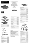
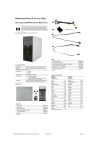
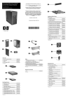
HP Compaq Business Desktop
dc7100 Series Personal Computer
Illustrated Parts Map
Small Form Factor
© 2004 Hewlett-Packard Development Company, L.P.
Mass Storage Devices (not illustrated)
HP and the HP logo are trademarks of Hewlett-Packard
Development Company, L.P.
40 GB\7200 RPM SATA hard drive
80 GB\7200 RPM SATA hard drive
345713-005
All other product names mentioned herein may be
trademarks of their respective companies.
120 GB\7200 RPM SATA hard drive
365556-001
160 GB\7200 RPM SATA hard drive
345712-005
HP shall not be liable for technical or editorial errors or
omissions contained herein. The information in this
document is provided “as is” without warranty of any kind
and is subject to change without notice. The warranties for
HP products are set forth in the express limited warranty
statements accompanying such products. Nothing herein
should be construed as constituting an additional
warranty.
September 2004
365555-001
Diskette drive with mounting screws
333505-005
48X CD-ROM drive with mounting screws
326773-005
52X CD-ROM drive
333969-005
48X/32X/48X CD-RW
346788-005
48X/32X/48X +16X DVD/CD-RW
359493-005
8X DVD+R/RW
358688-005
16/40X DVD ROM Drive
325313-005
Zip 250 Drive with mounting bracket
333504-005
Zip 250 drive without mounting bracket
326772-005
MultiBay Components
MultiBay drive adapter
Document Number
361291-001
335805-005
Diskette drive, MultiBay
335169-005
24X CD-ROM MultiBay drive
325314-005
24X/24X/24X/8X CD-RW/DVD ROM MultiBay
346789-005
8X/24X DVD-ROM MultiBay drive
325316-005
Miscellaneous Parts
Standard and Optional Boards
System Unit
1
Computer cover assy with front bezel and no inserts
378007-001
1
Computer cover assembly with front bezel and no
inserts (not painted, for Blue Angel use only)
367855-001
1
Front bezel assembly with no inserts
368086-001
1
Front bezel only, Blue Angel
378046-001
*
5.25” Bay bezel blank (carbonite)
335937-005
2
CD drive bezel with diskette drive
370501-001
2
CD drive bezel with diskette drive (Blue Angel)
374792-001
3
CD drive bezel without diskette drive
367852-001
4
CD drive bezel with Zip drive
370504-001
4
CD drive bezel with Zip drive (Blue Angel)
374793-001
5
Speaker with alcohol pad and thermal grease
368084-001
367857-001
1
System board with alcohol pad and thermal grease
361682-001
6
Heatsink with thermal grease and alcohol pad
2
Riser board (riser board is spared complete with
371291-001
expansion/riser card holder and computer backwall )
7
Chassis fan
366641-001
*
Heatsink duct baffle
375514-001
Memory Modules
*
128 MB/400 MHz FSB
335697-005
2
Power supply, PFC
350030-001
*
256 MB/400 MHz FSB
335698-005
3
Chassis assembly
not spared
*
512 MB/400 MHz FSB
335699-005
*
1.0 GB/400 MHZ FSB
335700-005
Intel Pentium 4 Processors with alcohol pad and thermal grease
8
Heatsink retention plate with thumbscrew
370709-001
9
Solenoid lock with cable
367854-001
*
Hood sensor
267529-005
*
Mouse, 2-Button, PS/2 with scroll wheel
323614-005
*
Mouse, 2-Button, USB, optical with scroll wheel
323615-005
*
Mouse, 2-Button, USB, with scroll wheel
323617-005
*
Power switch holder with LED holders (use with
368387-001 switch)
370857-001
*
2.8 GHz\800 MHz FSB, 1MB cache
367594-001
*
3.0 GHz\800 MHz FSB, 1MB cache
366643-001
*
3.2 GHz\800 MHz FSB, 1MB cache
366644-001
*
Drive Key, 16 MB
324780-005
*
3.4 GHz\800 MHz FSB, 1MB cache
367415-001
*
Drive Key, 128 MB
349988-005
*
3.6 GHz\800 MHz FSB, 1MB cache
367416-001
*
Drive Key, 256 MB
344249-005
*
Real-time-clock battery
153099-001
377661-001
Other Cards
*
TPM security module
366504-001
*
Expansion card retainer kit
*
PCI Modem, International, FH bracket
361286-021
*
Port control cover
367856-001
*
PCI Modem, International, LP bracket
361287-021
*
Universal clamp lock without cable
335808-005
*
Broadcom Gigabit NIC, FH bracket
321793-005
*
Universal clamp lock with cable
335809-005
*
Broadcom Gigabit NIC, LP bracket
367853-001
*
Flying serial port with cable
370500-001
*
Intel Gigabit NIC
314901-005
*
Intel Pro 10/100/1000 MT NIC, LP bracket
338154-005
*
FireWire 1394 card, 2 ext/1 int port, LP bracket
361551-001
*
FireWire 1394 card, 2 ext/1 int port, FH bracket
361552-001
*Not shown
#The heatsink must be removed before removing the speake. Make sure
the mating surfaces between the heatsink and the processor have been
cleaned with the alcohol pad provieded and fresh thermal grease has
been applied when reinstalling the heatsink.
*
PCI serial port card without internal cable/mtg bkt.
(see cable 302652-005)
283984-005
Miscellaneous Screw Kit (not illustrated)
Wireless LAN adapters (802.11b)
*
11 channel, FH bracket - use cable 333365-005
332963-005
Miscellaneous screw kit
*
13 channel, FH bracket - use cable 333365-005
333364-005
M3 x 5mm, hitop (263585-001) 4 ea
368388-001
*
13 channel, LP bracket - use cable 333365-005
354900-005
#6-32 x .250, hitop (262508-001) 8 ea
Power switch/LED cable - use switch holder
(370857-001)
368387-001
Graphics Solutions
3
Audio cable (CD to system board) (387527-001)
4
Cables
1
2
SATA hard drive cable, 24” (326965-007)
#6-32 x .250, pan head (101517-067) 3 ea
*
4 Layer ADD2 Graphics, LP bracket
361264-001
#6-32 x .312, hitop (262508-002) 4 ea
149806-001
*
ATI RV370 VGA graphics, 64M, LP bracket
364833-001
#6-19 x .312, pan head (101346-068) 2 ea
Front I/O device with cable
368386-001
*
ATI RV370 VGA graphics, 128M, LP bracket
364834-001
#6-19 x .315, T15 head (331310-001) 2 ea
*
Diskette drive cable (168999-006)
370499-001
*
UATA data cable, 8.6” (108950-054)
368389-001
*
Cable for PCI serial port card (use with 283984-005) 302652-005
*
Cable for Wireless LAN (use with 332963-005,
333364-005, 354900-005, 354901-005)
333365-005
*
Y-adapter power cable
374791-001
*Not shown
*Not shown
LP= Low profile mouinting bracket
FH = Full height mounting bracket
See next page for keyboard spares
337237-005
Keyboards (not illustrated)
PS/2, Basic
USB, Basic
USB, Modular
Computer Diagnostic LEDs (on front of computer)
355630-xxx
355631-xxx
355102-xxx
LED
Color
LED/Beep Activity
State/Message
Power
Green
On
(S0) Computer on
Arabic
-175
German
-045
Portuguese
-135
Power
Green
1 blink every 2 seconds
(S1) Suspend Mode
Belgian
-185
Greek
-155
Russian
-255
Power
Green
1 blink every 2 seconds
(S3) Suspend to RAM
BHCSY
-B45
Hebrew
-BB5
Slovakian
-235
Brazilian Portuguese
-205
Hungarian
-215
Spanish
-075
Czech
-225
International**
-B35
Swedish
-105
Danish
-085
Italian
-065
Swiss
-115
Europe*
-025
Japanese
-295
Taiwanese
-AB5
Finnish
-355
Korean (Hanguel)
-KD5
Thai
-285
French
-055
LA Spanish
-165
Turkish
-145
French Arabic
-DE5
Norwegian
-095
U.S.
-005
French Canadian
-125
PRC
-AA5
U.K.
-035
* For 355102 only
**Not for 355102
USB Basic Keyboard (not illustrated)
Europe, gray and carbonite (Blue Angel)
Power
Clear
Off
(S4) Hibernation
Power
Clear
Off
(S5) Computer off
Power
Red*
2 blinks 1 second apart
CPU thermal shutdown
Power
Red*
3 blinks 1 second apart
CPU not installed
Power
Red*
4 blinks 1 second apart
Power supply overload (crow bar)
Power
Red*
5 blinks 1 second apart
Defective or missing memory
Power
Red*
6 blinks 1 second apart
Defective or missing graphics
Power
Red*
7 blinks 1 second apart
System board failure (detected prior to video)
Power
Red*
8 blinks 1 second apart
Invalid ROM based on checksum
Power
Red*
9 blinks 1 second apart
System not fetching code
Power
Red*
10 blinks 1 second apart
System hang while loading an option ROM
Hard Drive
Green
Blinking
Hard drive activity
*Blinking codes are repeated after a 2 second pause. Beeps stop after fifth iteration but LEDs continue until problem is
resolved.
355632-B35
Keyboard Diagnostic LEDs, PS/2 Keyboards Only
LED
Color
LED Activity
State/Message
Num, Caps,
Scroll Lock
Green
On (Rising Tone)
ROM reflashed successfully
Num Lock
Green
On
ROMPaq diskette not present, is bad, or drive
not ready.*
Caps Lock
Green
On
Enter password.
Num, Caps,
Scroll Lock
Green
Blink On in sequence, one at a
time - N, C, SL
Keyboard locked in network mode
* Insert valid ROMPaq diskette in drive A. Turn power switch off, then on to reflash ROM. If ROM flash is successful, all
three keyboard LEDs will light up, and you will hear a rising tone series of beeps. Remove diskette and turn power off,
then on to restart the computer. For more information about flashing the ROM, refer to the Troubleshooting guide.
Clearing CMOS
The computer's configuration (CMOS) may occasionally be corrupted. If it is, it is necessary to clear the CMOS
memory using switch SW50.
To clear and reset the configuration, perform the following procedure:
1. Prepare the computer for disassembly.
Ä
System Board Connectors and Jumpers (position of some untitled components may vary in location)
2.
3.
4.
5.
CAUTION: The power cord must be disconnected from the power source before pushing the Clear CMOS
Button (NOTE: All LEDs on the board should be OFF). Failure to do so may damage the system board
Remove the access panel.
Press the CMOS button located on the system board and keep it depressed for 5 seconds.
Replace the access panel.
Turn the computer on and run F10 Computer Setup (Setup-utility) to reconfigure the system.
CR1
5V Aux power
P24
USB connector, front panel
E14
Boot block
P27
Multi Bay
E49
Password jumper
P29
SCSI LED connector
Disabling or Clearing the Power-On and Setup Passwords
J20
PCI slot 1
P52
Serial port “B”
J21
PCI slot 2
P54
Serial Port “A”
J31
PCI Express x1
P60
Primary Serial ATA (SATA) Port
J41
PCI Express x16
P61
Secondary Serial ATA (SATA) Port
P1
Main power (24 pin)
P124
Hood lock
1.
2.
3.
4.
5.
6.
P3
Processor VccP Power 12V (6 pin)
P125
Hood sensor
P5
Main power switch/LED
SW50
CMOS button
P6
Internal chassis speaker
XBT1
Battery
P7
CD audio in
XMM1
Memory socket
P8
Primary chassis fan
XMM2
Memory socket
P9
Secondary chassis fan
XMM3
Memory socket
P10
Diskette drive
XMM4
Memory socket
P11
Aux audio in
XU1
Microprocessor
P20
IDE
XU100
Security
P23
Front audio
Riser Board Connectors
J9020
PCI connector
J9021
PCI connector
System Hardware Interrupts
IRQ
System Function
IRQ
System Function
0
Timer Interrupt
8
Real-Time Clock
1
Keyboard
9
Unused
2
Interrupt Controller Cascade
10
Unused, available for PCI
3
Serial Port (COM B)
11
Unused, available for PCI
4
Serial Port (COM A)
12
Mouse
5
Unused, available for PCI
13
Coprocessor
6
Diskette Drive
14
Primary ATA (IDE) Controller
7
Parallel Port (LPT 1)
7.
8.
Turn off the computer and any external devices, and disconnect the power cord from the power outlet.
Remove the access panel.
Locate the header and jumper labeled E49.
Remove the jumper from pins 1 and 2. Place the jumper over pin 2 only, in order to avoid losing it.
Replace the access panel.
Plug in the computer and turn on power. Allow the operating system to start.
NOTE: Placing the jumper on pin 2 clears the current passwords and disables the password features.
To re-enable the password features, repeat steps 1-3, then replace the jumper on pins 1 and 2.
Repeat steps 5-6, then establish new passwords.
Refer to the Computer Setup (F10 Setup) instructions to establish new passwords.
Computer Setup (F10) Utility Features (not all features may be available)
File
System Information
About
Set Time and date
Replicated Setup
Default Setup
Apply Defaults and Exit
Ignore Changes and Exit
Save Changes and Exit
Storage
Device Configuration
Storage Options
DPS Self-Test
Boot Order
Security
Setup Password
Power-On Password
Password Options
Smart Cover
Embedded Security
Drivelock Security
Data Execution Prevention
Master Boot Record Security
Save Master Boot Record
Restore Master Boot Record
Device Security
Network Service Boot
System IDs
Power
OS Power Management
Hardware Power Management
Thermal
Advanced
Power-On Options
BIOS Power On
Onboard devices
PCI Devices
Bus Options
Device Options
PCI VGA Configuration