1
HP P6000 Command View User Guide
Abstract
This document describes how to use HP P6000 Command View (formerly HP Command View EVA) to manage HP Enterprise
Virtual Array models. It also describes how to use HP P6000 Performance Data Collector (formerly HP Command View EVAPerf)
to monitor array performance. This document is intended for HP P6000 Command View software and HP P6000 Performance
Data Collector users and administrators.
HP Part Number: T5494-96442
Published: October 2011
Edition: 13
© Copyright 2004–2011 Hewlett-Packard Development Company, L.P.
Confidential computer software. Valid license from HP required for possession, use or copying. Consistent with FAR 12.211 and 12.212, Commercial
Computer Software, Computer Software Documentation, and Technical Data for Commercial Items are licensed to the U.S. Government under
vendor's standard commercial license.
The information contained herein is subject to change without notice. The only warranties for HP products and services are set forth in the express
warranty statements accompanying such products and services. Nothing herein should be construed as constituting an additional warranty. HP shall
not be liable for technical or editorial errors or omissions contained herein.
Warranty
For information about HP product warranties, see the warranty information website:
http://www.hp.com/go/storagewarranty
Acknowledgments
Microsoft® and Windows® are U.S. registered trademarks of Microsoft Corporation.
NOTE: IPv6 is supported on server-based management HP Command View beginning with Version 8.0.2. IPv6 is supported on
array-based management HP Command View beginning with Version 9.2.
See Internet Protocol support.
Contents
1 Overview..................................................................................................7
Prerequisites.............................................................................................................................7
HP P6000 Command View software suite....................................................................................7
HP P6000 Command View features............................................................................................8
Server-based and array-based management.................................................................................8
HP Management Integration Framework....................................................................................10
User interface.........................................................................................................................11
Storage systems point of view..............................................................................................12
Settings point of view.........................................................................................................13
Accessing HP P6000 Command View.......................................................................................14
Internet Protocol support..........................................................................................................15
2 Managing security and passwords.............................................................16
Server-based HP P6000 Command View security groups.............................................................16
Array-based HP P6000 Command View security groups..............................................................16
Password protection for storage systems.....................................................................................16
Enabling management of a password-protected storage system.....................................................17
Disabling management of a password-protected storage system....................................................18
Setting a password for HP EVA storage systems..........................................................................18
Reestablishing communication with a password-protected storage system.......................................19
Single sign-on from HP Systems Insight Manager........................................................................19
3 Licensing HP P6000/EVA storage systems...................................................21
Licenses to use and license keys................................................................................................21
Activating an instant-on license.................................................................................................23
Retrieving licenses...................................................................................................................23
Entering license keys...............................................................................................................23
Importing licenses...................................................................................................................24
Deleting incorrectly entered license keys....................................................................................25
Displaying temporary license expiration date.............................................................................25
4 Provisioning storage..................................................................................26
Disk groups...........................................................................................................................26
Disk group capacity................................................................................................................28
Redundancy (Vraid) levels........................................................................................................29
Virtual disks...........................................................................................................................30
Hosts....................................................................................................................................32
Presentation...........................................................................................................................33
Online virtual disk migration....................................................................................................33
Mirrorclone migration..............................................................................................................33
Thin provisioning....................................................................................................................33
5 Replicating storage...................................................................................35
HP P6000 Business Copy software...........................................................................................35
Snapclones.......................................................................................................................35
Snapshots.........................................................................................................................36
Mirrorclones .....................................................................................................................37
Containers........................................................................................................................39
Optimizing replication performance..........................................................................................40
Planning for host I/O workloads..........................................................................................40
Optimizing snap creation....................................................................................................40
Using containers (preallocation)...........................................................................................40
Minimizing snapclone workloads.........................................................................................41
Contents
3
Minimizing the number of snapshots....................................................................................41
Setting virtual disk cache to write-through before a snapshot or snapclone.................................41
Suspending a DR group before a making a snapshot of a virtual disk.......................................41
Minimizing simultaneous replication operations.....................................................................41
HP P6000 Continuous Access software......................................................................................42
DR groups ........................................................................................................................42
Creating DR groups...........................................................................................................43
Data replication protocol options.........................................................................................43
6 Maintaining and managing HP P6000/EVA storage systems.........................45
Initializing storage systems.......................................................................................................45
Configure WEBES to generate alerts using Insight Remote Support...........................................45
User-initiated service mode..................................................................................................46
Uninitializing storage systems...................................................................................................47
Starting the storage system.......................................................................................................47
Shutting down the storage system..............................................................................................47
Hardware..............................................................................................................................49
Verifying hardware status.........................................................................................................50
Storage system identity information...........................................................................................50
Remote service test..................................................................................................................50
Updating HP controller software...............................................................................................51
Using multiple management servers to manage arrays.................................................................51
Configuring iSCSI devices........................................................................................................52
7 Monitoring storage system events................................................................53
Events overview......................................................................................................................53
Management server event log..............................................................................................53
Controller event log............................................................................................................53
Controller termination event log...........................................................................................54
Viewing events.......................................................................................................................54
Viewing additional information............................................................................................55
Corrective action code...................................................................................................55
More details.................................................................................................................55
Configuring event notification...................................................................................................55
Configuring host notification................................................................................................55
Entering hosts individually..............................................................................................55
Applying a customized host notification list.......................................................................56
Filtering events by severity...................................................................................................56
Selecting individual events..................................................................................................57
Applying a customized event configuration file.......................................................................57
Retrieving the parse file...........................................................................................................57
Retrieving the Management Information Base.............................................................................58
Sending the event file..............................................................................................................59
8 Configuring HP P6000 Command View (advanced tasks)..............................60
Setting user interface options....................................................................................................60
Creating page footer messages................................................................................................60
Setting audit logging options...................................................................................................61
Setting a remote location for audit logs.................................................................................61
Changing port and timeout parameters.....................................................................................62
Changing the login credentials (array-based management)..........................................................62
Running HP P6000 Command View in a multi-homed environment................................................63
9 Troubleshooting HP P6000 Command View.................................................64
Optimizing performance.........................................................................................................64
Restarting the HP P6000 Command View service........................................................................64
Using the right-click menu........................................................................................................64
4
Contents
Changing system time causes your session to end.......................................................................64
Navigation pane lists duplicate arrays.......................................................................................65
Failed communication path between management server and array..............................................65
Error messages in the user interface..........................................................................................66
Failed communication link to iSCSI devices................................................................................66
Failed connection warning for empty controller host ports............................................................66
Failed entities reported on the disk enclosure..............................................................................66
Troubleshooting access to array-based HP P6000 Command View................................................67
Virtual disk sizes displayed incorrectly.......................................................................................68
IP_Filter page incorrectly displays IPv6 address...........................................................................68
Unexpected behavior when using older Windows HBA driver.......................................................68
Storage system connection down error message..........................................................................68
Version numbers differ.............................................................................................................69
DR group, host port data replication settings page help not displayed...........................................69
WEBES 5.5 receiving events inconsistently.................................................................................69
Client applications not notified when disks are grouped using Add disks ......................................69
10 Monitoring array performance using HP P6000 Performance Data Collector...70
Components..........................................................................................................................70
HP P6000 Performance Data Collector server side logging of performance and state data...............71
Performance and state logs retrieval from HP P6000 Performance Data Collector client...............71
Configuration file for performance and state data logging...........................................................73
Configuring HP P6000 Performance Data Collector.....................................................................74
Events and logs......................................................................................................................74
Logging configuration file........................................................................................................74
Configuration recommendations...............................................................................................75
Connecting to HP P6000 Performance Data Collector remotely.....................................................75
SSL protocol......................................................................................................................76
Prohibited commands.........................................................................................................76
Backward compatibility......................................................................................................77
Using friendly names...............................................................................................................77
Creating the friendly names host file.....................................................................................77
Adding friendly names.......................................................................................................77
Mapping worldwide names to friendly names........................................................................78
Adding friendly names manually..........................................................................................78
Using short names.............................................................................................................79
Using the command line interface.............................................................................................80
Viewing arrays..................................................................................................................80
Specifying the output..........................................................................................................80
Commands.......................................................................................................................82
Command modifiers...........................................................................................................84
Using the graphical user interface.............................................................................................85
Data filtering.....................................................................................................................87
Configure filtering.........................................................................................................87
Objects and counters.........................................................................................................87
HP EVA storage array....................................................................................................88
HP EVA storage controller..............................................................................................88
HP EVA virtual disk........................................................................................................88
HP EVA virtual disk group..............................................................................................89
HP EVA host connection.................................................................................................90
HP EVA host port statistics..............................................................................................90
HP EVA physical disk.....................................................................................................91
HP EVA physical disk group............................................................................................91
HP EVA DR tunnels........................................................................................................92
HP EVA DR Group Information........................................................................................93
Contents
5
11 Support and other resources.....................................................................94
Contacting HP........................................................................................................................94
HP technical support..........................................................................................................94
Subscription service............................................................................................................94
Documentation feedback....................................................................................................94
Product feedback...............................................................................................................94
Related information.................................................................................................................94
Documentation..................................................................................................................94
Websites..........................................................................................................................95
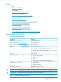
Typographical conventions ......................................................................................................95
A HP array event code formats and descriptions..............................................96
Event code format...................................................................................................................96
Event code types and descriptions.............................................................................................96
Software component IDs.....................................................................................................96
Corrective action codes......................................................................................................97
Event information packet (EIP) types......................................................................................97
Coupled crash control codes...............................................................................................98
Dump/restart control codes.................................................................................................99
Glossary..................................................................................................100
Index.......................................................................................................103
6
Contents
1 Overview
This chapter provides an overview of the HP P6000 Command View software suite.
IMPORTANT: General references to HP P6000 Command View may also refer to earlier versions
of HP Command View EVA. P6000 is the new branding for the Enterprise Virtual Array product
family.
Prerequisites
HP P6000 Command View must be installed on at least one of the following:
•
HP 4400 Enterprise Virtual Array (EVA4400), P6300 Enterprise Virtual Array (P6300 EVA),
or P6500 Enterprise Virtual Array (P6500 EVA) management module
•
General-purpose server
•
Dedicated management server
•
HP X1000/X3000 Network Storage Systems and Gateways
Earlier versions of HP P6000 Command View were required to be installed on a management
server. HP P6000 Command View EVA and Command View EVA 8.1 or later is installed on the
management module (9.4 or later on the P6300/P6500 EVAs), eliminating the need for a separate
management server. Other arrays continue to require a management server.
HP P6000 Command View software suite
Use the HP P6000 Command View software suite to configure, manage, and monitor HP's family
of advanced, enterprise storage arrays. The software suite includes:
•
HP P6000 Command View—Use the graphical user interface for initial configuration, storage
provisioning, and ongoing storage system management and monitoring.
•
HP Storage System Scripting Utility—Use the command line interface to script and run repetitive
and complex configuration tasks. See HP Storage Scripting Utility Reference for more
information.
•
HP P6000 Performance Data Collector—Use this tool to monitor array performance (server-based
management only).
•
Storage Management Initiative Specification for P6000 Enterprise Virtual Array (SMI-S
EVA)—Install SMI-S EVA on a management server to provide a common management interface
in a server-based management environment. It is a standard management interface developed
by SNIA to ease the management burden in multi-vendor SAN environments.
•
HP Management Integration Framework (MIF)—Use the interface provided by the HP MIF
software to provide storage-related security for HP P6000 Command View.
•
HP P6000 Performance Advisor—Use this tool to monitor HP P6000 storage systems and
collect metrics to analyze performance (server-based management only).
•
HP P6000 SmartStart—You can use this DVD-based wizard to install HP P6000 Command
View. The wizard also helps you configure, provision and mount storage volumes on Windows
and Linux servers.
This document describes how to use HP P6000 Command View and HP P6000 Performance Data
Collector. For information about other components of the software suite, see the online help or the
following:
•
HP Storage System Scripting Utility Reference
•
HP Management Integration Framework Administrator Guide
Prerequisites
7
•
HP P6000 Performance Advisor User Guide
•
HP P6000 SmartStart User Guide
HP P6000 Command View features
HP P6000 Command View enables you to:
•
Manage storage security and passwords
•
License storage systems
•
Provision storage to hosts
•
Replicate storage using HP P6000 Business Copy and HP P6000 Continuous Access
•
Maintain and manage storage systems
•
Monitor storage system events
•
Monitor performance data
Server-based and array-based management
HP P6000 Command View is available in server-based and array-based versions.
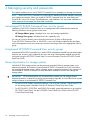
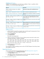
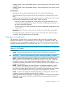
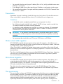
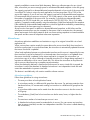
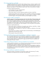
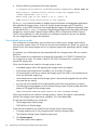
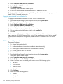
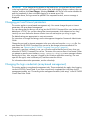
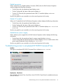
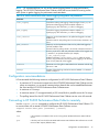
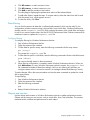
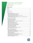
Server-based management. The server-based version of HP P6000 Command View is installed on
a management server which is connected to one or more HP EVA storage arrays. See Figure 1 (page
9). All components of the software suite (HP P6000 Command View, HP P6000 Performance
Data Collector, HP Storage System Scripting Utility, HP P6000 Performance Advisor, and SMI-S
EVA) can be installed on the server. Server-based management can be used with all P6000 storage
arrays.
8
Overview
IMPORTANT: HP P6000 Command View relies on the IP address assigned to the server for
management lock verification. Therefore, the HP P6000 Command View server must have a unique
IP address to ensure proper control locking.
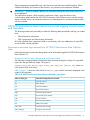
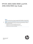
Figure 1 Server-based configuration
1
5
4
3
2
6
1. LAN
4. Browsing computer
2. SAN
5. Hosts
3. Management server
6. HP EVA storage systems
Figure 1 (page 9) shows multiple HP EVA storage arrays and hosts in a Fibre Channel SAN being
managed by one instance of server-based HP P6000 Command View on a management server.
The management server is also connected to a LAN so that users and administrators can browse
to the HP P6000 Command View interface.
HP P6000 Command View does not require hosts to be connected to the LAN. However, a LAN
connection can be a requirement of other HP server-based applications.
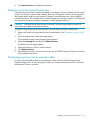
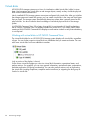
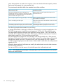
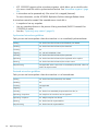
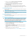
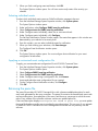
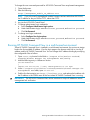
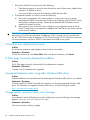
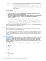
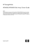
Array-based management. The array-based version of HP P6000 Command View comes
factory-installed on HP EVA4400, P6300 EVA, and P6500 EVA storage arrays. With these storage
arrays, a separate management server is not required. Only one component of the software suite,
HP P6000 Command View itself, is installed on a storage array. The other components of the
software suite can be installed on a separate server. See Figure 2 (page 10).
Server-based and array-based management
9
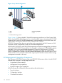
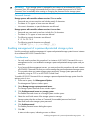
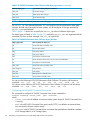
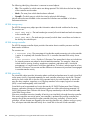
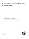
Figure 2 Array-based configuration
1
5
4
2
3
1. LAN
4. Browsing computer
2. SAN
5. Hosts
3. HP EVA4400 storage systems
Figure 2 (page 10) shows multiple HP EVA4400 storage arrays and hosts in a Fibre Channel SAN.
In this case, each EVA4400 storage array has a factory-installed instance of array-based HP P6000
Command View. Each HP EVA4400 storage array is also connected to a LAN so that users and
administrators can browse to each HP P6000 Command View interface.
HP P6000 Command View does not require hosts to be connected to the LAN. However, a LAN
connection can be a requirement of other HP server-based applications.
HP EVA4400, P6300 EVA, and P6500 EVA storage arrays can also be managed from an instance
of server-based HP P6000 Command View. For example, to configure an HP EVA4400 for remote
replication, you must use server-based management. A feature in both versions of HP P6000
Command View allows HP EVAs to be selectively managed by more than one instance of HP
P6000 Command View. However, only one instance can manage an EVA at a time. The HP P6000
Command View server must take control of the array away from all other instances before issuing
management commands to the array.
HP Management Integration Framework
Each instance of HP P6000 Command View and HP P6000 Performance Advisor includes HP MIF
software which provides HP storage applications with:
•
Single Pane of Glass interface
•
Management Group capabilities
•
Enhanced single sign-on capabilities
HP MIF software also includes the following interfaces for administrators:
10
•
Security interface
•
Configuration interface
•
Command line interface
Overview
For more information, see the online help or the HP Management Integration Framework
Administrator Guide and the HP Management Integration Framework Maintenance and Service
Guide.
User interface
HP P6000 Command View uses a SPoG interface, which can display multiple HP P6000 storage
software applications in a single browser window. When multiple instances of server-based or
array-based HP P6000 Command View are in the same Management Group, the SPoG interface
displays all of the storage systems managed by those instances.
NOTE: If you add more than one array-based management instance to a Management Group,
HP recommends that you assign a unique name to each instance.
The SPoG interface has two points of view:
•
The storage systems point of view is the primary means of viewing and managing the storage
systems in a management group. If you have Performance Advisor installed, you can view
storage system performance information by clicking the Performance tab.
•
The settings point of view is the primary means of viewing and changing options in HP P6000
Command View and HP P6000 Performance Advisor.
For information about HP P6000 Performance Advisor, see the HP P6000 Performance Advisor
User Guide or online help.
NOTE: HP P6000 Command View does not support the internationalization and localization
(i18n) format for object names and comments.
The following illustrations show examples of the HP P6000 Command View interface.
User interface
11
Point of view selectors
Located on the lower left of the window, these selectors enable you to select the point of view that
is displayed. The selector for the active point of view is colored orange.
•
When the storage systems point of view is selected, all of the managed and initialized storage
systems in the Management Group are displayed in an expandable tree in the navigation
pane.
•
When the settings point of view is selected, storage applications and folders of unmanaged
and uninitialized storage systems are displayed in the navigation pane. In the settings point
of view you can change storage application settings, assume management control of
unmanaged storage systems, and initialize storage systems.
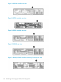
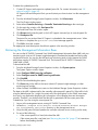
Storage systems point of view
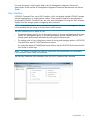
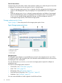
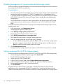
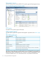
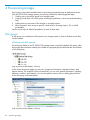
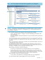
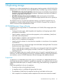
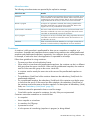
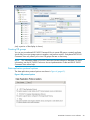
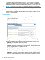
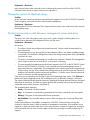
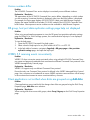
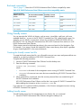
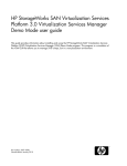
Figure 3 (page 12) shows the panes for the storage systems point of view.
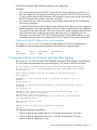
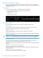
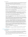
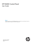
Figure 3 Storage systems point of view
1. Point of view selectors
4. Aspect tabs
2. Navigation pane
5. Session pane
3. Content pane
Navigation pane
The navigation pane displays an expandable resource tree for the selected point of view. When
you select a resource in the navigation pane, the information and available actions for the resource
are displayed in the content pane.
You can click the plus (+) or minus (–) icon next to a storage system to expand or collapse its
components tree.
The tree for each storage system consists of:
•
Virtual disks—See “Virtual disks” (page 30)
•
Hosts—See “Hosts” (page 32)
•
Disk groups—See “Disk groups” (page 26)
•
Data replication (DR) groups—See “DR groups ” (page 42)
•
Hardware—See “Hardware” (page 49)
You can create subfolders to further organize virtual disks and hosts.
12
Overview
Content pane
The content pane displays information and actions that you can perform on the storage system or
component that is selected in the Navigation pane.
Aspect tabs
The displayed aspect tabs depend on your configuration. They display organized content based
on your HP storage applications. For example, the Management aspect tab includes content from
the HP P6000 Command View application and the Performance tab includes content from the HP
P6000 Performance Advisor application. For more information about the Performance tab, see HP
P6000 Performance Advisor User Guide.
Session pane
The session pane displays the name of the Management Group in which the resources are members,
the name of the user that is logged in, a link to online help, and a logout button.
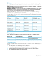
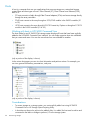
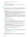
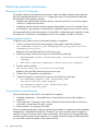
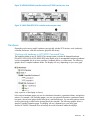
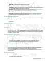
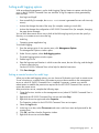
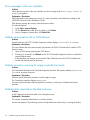
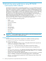
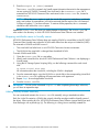
Settings point of view
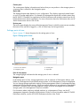
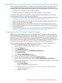
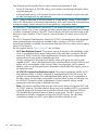
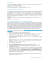
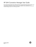
Figure 4 (page 13) shows the panes for the settings point of view.
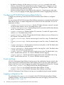
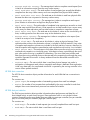
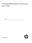
Figure 4 Settings point of view
1. Point of view selectors
3. Content pane
2. Navigation pane
4. Aspect tab
Point of view selector
The orange highlight indicates that the settings point of view is selected.
Navigation pane
In the settings point of view, storage applications such as instances of Performance Advisor, and
folders of unmanaged and uninitialized storage systems in the Management Group are displayed.
You can change storage application settings, assume management control of unmanaged storage
systems and initialize storage systems. If there are multiple instances of server-based or array-based
HP P6000 Command View in the Management Group, all of the unmanaged and uninitialized
storage system in the Management Group are included.
For information about combining multiple machines in a Management Group, see the HP
Management Integration Framework Administrator Guide. For more information about HP P6000
Performance Advisor, see the HP P6000 Performance Advisor User Guide.
User interface
13
Content pane
Displays information and actions that you can perform on the resource that you selected in the
navigation pane.
Aspect tabs
The displayed aspect tabs depend on your configuration. They display organized content based
on your HP storage applications. For example, the Management aspect tab includes content from
the HP P6000 Command View application and the Performance tab includes content from the HP
P6000 Performance Advisor application. For more information about the performance tab, see
HP P6000 Performance Advisor User Guide.
Accessing HP P6000 Command View
IMPORTANT: The first time you log in to HP P6000 Command View from a browser, the following
message appears:
Failed to connect to Discovery. The Management Group (MG) certificate
may not be installed. Please refer to help for more information.
Click here to install the Management Group certificate
You must install the Management Group security certificate and refresh the browser to unblock the
connection.
Browsing to server-based HP P6000 Command View
1.
2.
Open a browser.
Using the network name or IP address of the server on which HP P6000 Command View is
installed, enter:
https://server_name or IP_address:2374
The HP P6000 Command View login window opens.
3.
Enter a valid user name and password, and click Logon. Valid user names are members of
the appropriate local or domain group on the management server. See “Server-based HP
P6000 Command View security groups” (page 16).
The HP P6000 Command View user interface opens.
Running server-based HP P6000 Command View from the desktop
1.
2.
3.
On the management server desktop, locate the icon for HP P6000 Command View.
Double-click the icon. The HP P6000 Command View login window opens.
Enter a valid user name and password, and click Logon. Valid user names are members of
the appropriate local or domain group on the management server. See “Server-based HP
P6000 Command View security groups” (page 16).
The HP P6000 Command View user interface opens.
The port to access server-based HP P6000 Command View can be changed, if necessary. See
“Changing port and timeout parameters” (page 62)
Browsing to array-based HP P6000 Command View
1.
2.
Open a browser.
Using the network name or IP address of the HP EVA4400, P6300, or P6500 storage array,
enter:
https://array_name or IP_address:2374/SPoG
The HP P6000 Command View login window opens.
14
Overview
3.
Enter a valid user name and password. This is the same user name and password to log onto
the HP P6000 Control Panel. See the HP P6000 Control Panel User Guide.
You can also launch HP P6000 Command View from the HP P6000 Control Panel GUI.
Internet Protocol support
HP P6000 Command View is designed for use with internet protocols as follows:
•
Server-based versions 8.0.2 and later—IPv4, IPv6, and mixed IPv4/IPv6 networks
•
Server-based versions earlier than 8.0.2—IPv4 networks only
•
Array-based 9.2 and later—IPv4, IPv6, and mixed IPv4/IPv6 networks
•
Array-based versions earlier than 9.2—IPv4 networks only
•
Internet Explorer 8.0 and later, or Mozilla FireFox 3.6 and later is required to access HP
P6000 Command View using the IPv6 address.
•
For server-based configurations, if IPv4 and IPv6 are installed on a single system, HP P6000
Command View starts on the IPv4 address by default. If you want to start HP P6000 Command
View on a specific address, you must add the address entry under the webserver section
of the cveva.cfg configuration file. For example, to start HP P6000 Command View on
IPv6, enter address 0::0 under the webserver section of cveva.cfg.
•
Using the IPv6 link local address to run the management server can result in connectivity issues.
•
For server-based systems, the management server is available on either the IPv4 or the IPv6
address only.
NOTE: HP P6000 Performance Data Collector has the same behavior with IPv6 as HP P6000
Command View. To start HP P6000 Performance Data Collector on a specific IPv6 address, you
must add the evapdcs.address entry in the evaperf.conf file and specify the address.
IP address formats
IP addresses in IPv6 have a different format than IPv4.
•
IPv6 IP addresses are generally shown in eight groups of four hexadecimal digits, separated
by colons, for example, 2001:0db8:85a3:08d3:1319:8a2e:0370:7334.
•
IPv4 IP address are generally shown in decimal notation, separated by dots (periods), for
example: 192.0.2.235.
•
IPv6 IP addresses with port numbers are enclosed in brackets to avoid confusion with port
numbers, for example:
https://[2001:0db8:85a3:08d3:1319:8a2e:0370:7344]:443/.
•
IPv4 addresses with port number do not use brackets.
Internet Protocol support
15
2 Managing security and passwords
This chapter explains how to use HP P6000 Command View to manage your storage environment.
NOTE: See the HP P6000 Command View online help for detailed procedures related to managing
your storage environment. When you install HP P6000 Command View, the initial folders are
Virtual Disks, Hosts, Disk Groups, Data Replication, and Hardware. You can create subfolders to
further organize and manage your hosts and virtual disks.
Server-based HP P6000 Command View security groups
Installation of HP P6000 Command View on a management server automatically creates the
following Windows security groups on the server:
•
HP Storage Admins group—Members have view and manage capabilities.
•
HP Storage Users group—Members have view capability only.
You can set a local or domain user to have the permissions of either of these groups.
To use HP P6000 Command View or SMI-S EVA, a user with Windows administrator privileges
for the management server must create user accounts and assign them to the appropriate security
group.
Array-based HP P6000 Command View security groups
Array-based HP P6000 Command View in each HP EVA management module has one administrator
and one user account. Login credentials are set in the array's management module and can be
configured using the HP P6000 Control Panel. For more information, see the HP P6000 Control
Panel User Guide.
Password protection for storage systems
Individual HP EVA storage systems can be password protected. When a storage system is not
password protected, all instances of server-based HP P6000 Command View in the SAN fabric
can manage the storage system. When a storage system is password protected, only instances of
server-based HP P6000 Command View that have been enabled for access can manage the
storage system.
IMPORTANT: HP recommends that you use passwords to protect your HP storage systems.
Password protection is optional but strongly recommended, especially for SAN fabrics that include
multiple instances of server-based HP P6000 Command View.
16
•
For most HP EVA models, password protection is set using the Operator Control Panel (OCP)
on the storage system controllers. See the HP Enterprise Virtual Array User Guide.
•
For HP EVA4400, P6300 EVA, and P6500 EVA models, password protection is set using the
HP P6000 Control Panel. See the HP P6000 Control Panel User Guide or the HP P6000
Control Panel online help.
Managing security and passwords
IMPORTANT: If your storage system is managed by an instance of server-based HP P6000
Command View, HP strongly recommends that you store or update the password in HP P6000
Command View immediately after creating or changing the password on the storage system.
Password formats
Storage systems with controller software versions 5.1xx or earlier
•
Passwords are not case sensitive and include exactly 8 characters.
•
The letters A–Z in upper or lower case are allowed.
•
No numeric characters or special characters are allowed.
Storage systems with controller software versions 6.xxx or later
•
Passwords are case sensitive and can include 8 to 16 characters.
•
The letters A–Z in upper or lower case are allowed.
•
The following numeric characters are allowed:
0123456789
nl
•
The following special characters are allowed:
!"#$%&'()*+,-./:;<=>?@[]^_{|}
nl
Enabling management of a password-protected storage system
Use this procedure to enable management of a password-protected storage system from an instance
of server-based HP P6000 Command View.
Considerations
•
You only need to perform this procedure if an instance of HP P6000 Command View on a
management server is not enabled to manage a password-protected storage system and you
want it to.
•
If you have multiple management servers, you must perform this procedure with each instance
of HP P6000 Command View that you want to manage the password-protected storage system.
•
This procedure does not create storage system passwords. Storage system passwords are
created by using an OCP or an HP P6000 Control Panel.
To enable HP P6000 Command View to manage a password-protected storage system from the
settings point of view:
1. In the session pane, click Management Options.
The Management Options window opens.
2.
Select Manage storage system password access.
The Storage System Password Access window opens.
3.
Click Enable password access to a storage system.
The Enable Password Access to a Storage System window opens.
4.
Select the world wide name of the storage system to manage.
Storage systems that do not have a Command View-enabled password are listed.
5.
6.
Enter and confirm the storage system password.
Click Enable password.
The Enable password access dialog box opens.
7.
Click OK.
A status window opens, indicating success or failure.
Enabling management of a password-protected storage system
17
Disabling management of a password-protected storage system
Use this procedure to disable management of a password-protected storage system from an instance
of server-based HP P6000 Command View.
Considerations
•
You only need to perform this procedure if you no longer want to manage a password-protected
storage system from an instance of HP P6000 Command View on a management server.
•
If you have multiple management servers, you must perform this procedure with each instance
of HP P6000 Command View that you no longer want to manage the password-protected
storage system.
•
This procedure does not remove or clear a password from the storage system itself. Storage
system passwords can only be removed or cleared from an OCP or an HP P6000 Control
Panel.
To disable HP P6000 Command View to manage a password-protected storage system from the
settings point of view:
1. In the session pane, click Management Options.
The Management Options window opens.
2.
Select Manage storage system password access.
The Storage System Password Access window opens.
3.
Select Disable password access to a storage system.
The Disable Password Access to Storage Systems page opens.
4.
5.
Select the storage system that you no longer want to manage.
•
To select multiple storage systems, press the Ctrl key while you select each storage system.
•
To select a range of storage systems, select the first storage system, and then press the
Shift key and click the last storage system in the range.
Click Disable password access.
Management of the storage system by the instance of HP P6000 Command View is ended.
Setting a password for HP EVA storage systems
Use this procedure to set the password on EVA4400, P6300 EVA, and P6500 EVA storage systems.
1. On the Management Module Properties page, click Launch OCP.
The HP P6000 Control Panel GUI opens.
2.
3.
4.
5.
6.
Log on to the HP P6000 Control Panel.
In the HP P6000 Control Panel, select Configure Administrator login options.
Under Management Server Password, enter the new password in the Password box.
Enter the password again in the Confirm Password box.
Click Set Password.
The password for an HP EVA4400, P6300 EVA, or P6500 EVA affects access by external
applications such as server-based HP P6000 Command View. It does not affect access by the
instance of array-based HP P6000 Command View that is internally installed on the storage system.
18
Managing security and passwords
Reestablishing communication with a password-protected storage system
A communication problem between an instance of server-based HP P6000 Command View and
a password-protected storage system can be caused when the stored password in HP P6000
Command View does not match the password that is set on a storage system. This can occur when:
•
The password on a storage system has been changed.
•
Controller software on a storage system has been updated to a newer version.
If you believe that a password mismatch is causing a communication problem with a storage
system, proceed as follows to synchronize the passwords.
1. In HP P6000 Command View, clear the stored password for the effected storage system. See
“Disabling management of a password-protected storage system” (page 18).
2. On the affected storage system, clear the password using the operator control panel (OCP).
See the user guide for your array model.
3. On the management server, stop and then restart the HP P6000 Command View service.
4. On the affected storage system, enter the new password using the OCP. See the user guide
for your array model.
5. In HP P6000 Command View, store the new password for the affected storage system. See
“Enabling management of a password-protected storage system” (page 17).
nl
Single sign-on from HP Systems Insight Manager
Single sign-on (SSO) enables you to have a single login from HP Systems Insight Manager (HP
SIM) by establishing a trust relationship with HP P6000 Command View. A user on HP SIM can
go directly to HP P6000 Command View without having to re-enter a user name and password.
The access level of the HP SIM account is passed to HP P6000 Command View; therefore, an
account with administrator rights in HP SIM will have administrator rights in HP P6000 Command
View and a user account in HP SIM will have user rights in HP P6000 Command View.
Perform the following steps to use single sign-on from HP SIM to HP P6000 Command View:
1. From the HP P6000 Command View management server:
a. Open HP P6000 Command View GUI at https://localhost:2374
b. Click the Settings tab.
c. Click Management options.
d. Under Security Options, select SIM/RSM trust relationships.
e. Click Install certificate.
f. Select System Insight Manager as type.
g. Enter 280 as the SIM Server IP address port.
h. Provide the necessary details, and then click Install certificate.
i. Return to the Server options page, and click Other Application Trust relationships.
j. Determine whether the HPEVA_SMIS_Provider certificate is installed. If it is not, install
the certificate as follows:
i. Click Install certificate.
ii. Provide an application name, such as SSO.
iii. Browse to <install_path>\Hewlett-Packard\SMI-S\EVAProvider\
config\HPSMISSSO.cert
iv. Install the certificate.
Reestablishing communication with a password-protected storage system
19
2.
Perform the following steps from the SIM server:
a. Discover the HP P6000 Command View management server.
Wait until the initial data collection for the attached arrays completes.
b.
c.
d.
Select the array from the SIM page.
Select the Tools & link tab.
Launch HP P6000 Command View using the URL of the HP P6000 Command View
web-based element manager.
An HP P6000 Command View login window opens.
e.
Enter your username and password.
NOTE:
20
Subsequent logins do not prompt for username and password.
Managing security and passwords
3 Licensing HP P6000/EVA storage systems
Licenses to use and license keys
License types
The following types of licenses to use (LTUs) are available for HP P6000/EVA storage systems:
•
HP P6000 Command View LTUs. These LTUs are required to manage a given storage system
with HP P6000 Command View.
Each HP P6000 storage system must be licensed with the appropriate HP P6000 Command
View LTUs to be in compliance with the End User License Agreement.
•
HP MPX200 LTUs. These LTUs provide the ability to interconnect SANs via a LAN/WAN,
connect an FC device to a SAN over a LAN/WAN, or migrate the data between source and
destination arrays. The LTUs are installed on the MPX200 controller.
•
HP P6000 Business Copy LTUs. These LTUs enable the use of optional local replication features,
such as snapshot, snapclone, and mirrorclone.
•
HP P6000 Continuous Access LTUs. These LTUs enable the use of optional remote replication
features.
•
HP P6000 Performance Advisor LTU. These LTUs allow you to monitor and analyze performance
of P6000 storage systems.
•
Thin provisioning LTU. This LTU enables the thin provisioning feature.
•
DC-Management LTU. This LTU enables the P6000 Dynamic Capacity Management feature.
NOTE: For the P6300/P6500 EVAs, the license keys for HP P6000 Dynamic Capacity
Management and thin provisioning are included with the HP P6000 Command View License
Entitlement.
Instant-on licenses
You can use the factory-installed instant-on license key to immediately start using the features with
the exception of P6000 Dynamic Capacity Management and thin provisioning. The instant-on key
is valid for all arrays managed by an HP P6000 Command View server and enables HP P6000
Command View, HP P6000 Business Copy, and HP P6000 Continuous Access with unlimited
capacity for 60 days from the first use. Upon expiration of the instant-on license key, these features
will be disabled. Your data is preserved and you can continue to use the array but cannot create
new resources. To continue using the features, you must obtain a permanent license key.
Permanent licenses
•
Licenses are available in various capacities to support the maximum capacity of the array.
Model-upgrade licenses are also available.
•
You can enter a license key before or after initializing the array. When a license key is
installed, the license immediately takes effect.
•
HP P6000 Command View, HP P6000 Business Copy, HP P6000 Performance Advisor, and
HP P6000 Continuous Access LTUs are locked to an array and are not transferable.
•
HP thin provisioning LTUs are model-locked.
When you install a permanent license, the temporary instant-on license no longer appears in the
license list.
Licenses to use and license keys
21
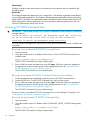
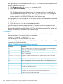
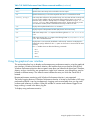
Data migration licenses
HP P6000 Command View and the MPX200 iSCSI controller support the Data Migration licenses.
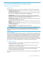
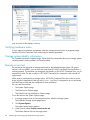
Figure 5 Initalized Storage System Properties window
FCIP licenses
The MPX200 iSCSI controller supports FCIP licenses.
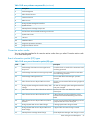
Model upgrade licensing
Only data-in-place upgrades are supported. Model upgrade is supported as shown Table 1 (page
22).
Table 1 Model upgrade support
You can upgrade from:
To:
EVA3000
EVA4100, EVA6100, or EVA8100
EVA4000
EVA4100, EVA6100, or EVA8100
EVA5000
EVA4100, EVA6100, or EVA8100
EVA6000
EVA6100 or EVA8100
EVA8000
EVA8100
EVA4400 (HSV300)
EVA4400 (HSV300-S), EVA6400, or EVA8400
EVA4400 (HSV300-S)
EVA4400 (HSV300), EVA6400, or EVA8400
P6300 (FC)
P6300 (FC-iSCSI), P6300 (iSCSI/FCoE), P6500 (FC, FC-iSCSI, or iSCSI/FCoE)
P6500 (FC)
P6500 (FC-iSCSI) or P6500 (iSCSI/FCoE)
Upgrading an array model requires a Model Upgrade license. Model Upgrade licenses are effective
only if there is a base permanent license for the lower version of controller. During installation, the
base permanent license is validated and if one is not found, a warning message displays to inform
you that the upgrade license is not in effect because there is no permanent unlimited license.
22
Licensing HP P6000/EVA storage systems
Obtaining license keys
To obtain a license:
1. Browse to HP Webware at http://webware.hp.com/.
2. Click Generate New Licenses.
3. Enter a username and password.
4. Enter the Order Number which can be found on your License Entitlement Certificate.
5. Select the licenses to purchase, and provide the WWN.
For more information about HP P6000 Command View LTUs, browse to:
http://h18006.www1.hp.com/products/storage/software/cmdvieweva/index.html
Under Product Information, click CV EVA Licensing.
Activating an instant-on license
NOTE:
This section applies to EVA4400, P6300 EVA, and P6500 EVAs only.
After initializing a storage system with array-based management, you must activate instant-on
licensing before you can use it. This is a one-time procedure. See also “Licenses to use and license
keys” (page 21).
To activate a license key from the storage system point of view:
1. In the navigation pane, select the storage system.
The Initialized Storage System Properties page opens.
2.
3.
Select the Licensing tab and click Install Licenses.
Click Activate Instant-on.
The instant-on license is activated.
Retrieving licenses
License keys can be retrieved from HP P6000 Command View using the Export Licenses option
within Server options. To store a copy of a key in a text file:
1. From the settings point of view, click Management Options.
2. Click Import/Export Licenses.
3. Click Export Licenses.
A pop-up window with File Download options appears.
4.
Click Save to save the license keys in a file on the local system.
Entering license keys
See the HP P6000 Enterprise Virtual Array License Key Installation Instructions shipped with the
product and available online.
Configuring email to receive LTUs
If you receive a license by email, HP recommends that you configure your email application to use
ASCII format to preserve the format of the information. To change an Microsoft Outlook message
format to ASCII:
1. In Outlook, select Tools→Options.
2. Select the Mail Format tab.
3. Under Message format, select Plain Text.
4. Click OK.
Activating an instant-on license
23
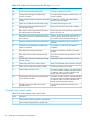
Validating the license
Validation occurs automatically to verify the license installation. If there is a problem with the
installation, one of the following messages appears:
Message
Description
ERROR: License String is not regular
structure please install the correct
license string
The license text does not fit the standard structure of a
license text, or contains error in checksum/any error.
ERROR: Cannot add expired license to EVA
You have entered an expired temporary license.
ERROR: License already exist in database
The license key has already been installed in the autopass
database.
Warning: license string got added with few A verification of the WWN and Model discovered an error.
warnings, License did not match the array As the license string is syntactically correct, the license
string is added to the autopass database but not to the
WWN and Model Type
selected array MLD.
Warning: License string got added with few The license key provides lower access than what is already
warnings, License string is of lower access installed.
and is of no effect
Warning: License string got added with few While importing a license, verification of the WWN and
Model discovered an error. This can occur when you add
warnings, License did not match for the
licenses for more than one array. Despite the warning, the
array WWN and Model Type
license is installed.
Warning: License string got added with few An imported license key provides lower access than what
warnings, License string is of lower access is already installed.
and is of no effect
Adding an LTU
1.
In the HP P6000 Command View navigation pane, select the specific storage system to license.
The Initialized Storage System Properties page opens.
2.
3.
Select the Licensing tab.
Click Install Licenses.
The Install Licenses page opens.
4.
Follow the instructions on the page. Copy only the key text from the email or online source,
including the annotation in quotes. For example,
ADSG
L762
QVCE
WRSX
5.
6.
C9AA
QKB2
ZSCH
4JUN
H9P9
HWR4
W4A9
M2UH
KHW3
KJVT
8E4K
KMDX
VVA4
D5KM
WJKW
CFNX
HWSN
EFVW
48WF
E3QS
Y9JL KMPL B89H MZVU DXAU 2CSM GHTG
TSNJ N6CJ Q9R9 LB2K QAJV QNMZ PSPQ
3YHV NK79 G4FB VP86 FCYX 5KG2 F6AH
“sample annotation”
Paste the license key into the text box.
Click Install Licenses.
For an alternative method of adding a license, see the HP P6000 Enterprise Virtual Array License
Key Installation Instructions.
Importing licenses
You
1.
2.
3.
24
can import licenses that were exported previously. See “Retrieving licenses” (page 23).
From the settings view, click Management Options.
Click Import/Export Licenses.
Under Import Licenses, provide the location of the file in the space indicated. You can also
use the Browse button to locate the file on the local system.
Licensing HP P6000/EVA storage systems
4.
Click Import Licenses to complete the operation.
Deleting incorrectly entered license keys
If a license key for an array is entered incorrectly (for example, a license is entered with the correct
WWN, but with the incorrect model number), the license will appear under the Licensing tab but
the licensed option might not work properly. Enabling a licensed option can include installing
multiple license keys. For example, there could be multiple keys for higher capacity (1 TB keys that
are cumulative in nature or capacity upgrades) or model upgrade scenarios.
CAUTION: Individual license keys cannot be removed. The following procedure removes all
license keys associated with the selected option.
To remove a license you must remove all licenses for that feature, and then reinstall them:
1. Retrieve all license keys associated with the licensed feature. See “Retrieving licenses” (page
23).
2. In the navigation pane, select the storage system.
The Initialized Storage System Properties page appears.
3.
Select the Licensing tab, and then click Remove Licenses.
The Remove licenses page appears.
4.
5.
6.
Select the feature for which to remove licenses.
Click Remove Licenses.
Reinstall the license keys. For more information, see HP P6000 Enterprise Virtual Array License
Key Installation Instructions.
Displaying temporary license expiration date
You can view the expiration date for the temporary license on the Initialized Storage System
Properties page section of the Licensing tab. When you install a permanent license for a product,
the temporary license is removed.
Deleting incorrectly entered license keys
25
4 Provisioning storage
Provisioning is the industry-standard term for providing networked storage to application servers.
With HP P6000/EVA storage systems, provisioning includes the following general steps:
1. Creating one or more disk groups on a storage system.
2. Creating virtual disks within disk groups and assigning attributes, such as size and redundancy
level.
3. Adding hosts as consumers of the storage on a storage system.
4. Allowing specific hosts access to specific virtual disks on a storage system. This is called
presentation.
See the online help for detailed procedures on each of these steps.
Disk groups
A disk group is a named pool of disk space on a storage system in which individual virtual disks
can be created.
Working with disk groups
The disk group folder for an HP P6000/EVA storage system includes the default disk group, other
disk groups that have been created, plus a folder of ungrouped physical disks that are not members
of any disk group.
(only a portion of the display is shown)
In the various disk group pages you can view component information, operational status, and
perform actions. For example, from the General tab, you can view general information, including
attributes, condition, and capacity. You can also perform actions such as adding physical disks
to the disk group and locating disks.
(only a portion of the display is shown)
26
Provisioning storage
Disk types
The disk type specifies the type of physical disk drives that can be included in a disk group. The
types are:
Online disk type. All physical drives must be Fibre Channel or enterprise SAS drives. This disk type
provides first tier performance and reliability.
Near-online disk type. All physical drives are lower cost, lower performance hybrid Fibre Channel
or midline SAS disk drives. Hybrid drives are dual ported, Fibre Attached Technology Adapted
(FATA) drives. This disk type provides second tier performance and reliability.
Solid state drive disk type. All physical drives must be solid state drives (SSD). This disk type
provides first tier, very high performance and reliability.
Disk type support varies with HP XCS controller software versions. The following table summarizes
support and typical uses.
Feature
Online
Near-online
Solid state drive
XCS support
All versions
All versions
XCS 09500000 or later
Physical disks
Fibre Channel/SAS drives
FATA/SAS drives
Solid state drives
Preferred usage
Preferred usage
Preferred usage
Typical uses
Disaster tolerance
Disk-to-disk backup
Preferred usage
Disk-to-tape backup
Preferred usage
Frequent file access
Preferred usage
Infrequent file access
High performance
Preferred usage
Preferred usage
Preferred usage
Virus attack recovery
Preferred usage
Preferred usage
Disk group types
When a disk group is created, it is assigned a disk group type: basic or enhanced (default).
Disk group type
Supported Vraid levels
EVA support
Basic
Vraid0, Vraid1, and Vraid 5
EVA4000/4100/4400/6000/
6100/6400/8000/8100/8400
Enhanced
Vraid0, Vraid1, Vraid5, and Vraid6
EVA4400/6400/8400 P6300/P6500 EVA
General guidelines
One disk group (the default) is created when the system is initialized. You can add disk groups as
needed.
•
Each physical disk drive can belong to only one disk group.
•
A single disk group may contain all the physical disk drives in the storage system.
•
Multiple virtual disks can be created in a disk group, up to the disk group's capacity.
•
Each virtual disk exists entirely within one disk group.
Disk groups
27
Number of physical disks in a group
•
With online and near-online disk types, the minimum number of physical disks is 8.
•
With the solid state drive disk type, the minimum number of physical disks is 6.
•
If the number of disks is not specified when creating a disk group, the minimum is assigned.
If the minimum number of disks is not available, the disk group cannot be created.
•
There is no maximum number of physical disks.
Disk group occupancy and occupancy alarm level
The term occupancy refers to the amount of disk space being used for user data in a disk group.
There are two occupancy alarm levels:
•
The warning level is the point (percent of capacity) at which the array issues a disk group
allocation warning message. The default warning alarm level is 70% of capacity.
•
The critical alarm level is the point (percent of capacity) at which the array issues a disk group
allocation critical message. The default critical alarm level is 90% of capacity.
For example, if a disk group's capacity is 200 GB, and the default alarm levels are set, a warning
is issued when the total capacity of the virtual disks in the disk group reaches 140 GB, and a
critical message is issued when the total capacity of the virtual disks in the disk group reaches 180
GB.
If you change the occupancy alarm default values, the critical alarm level must be greater than the
warning alarm level.
NOTE: HP P6000 Command View 9.x and earlier have a warning alarm level only. The default
value is 90%.
Disk group capacity
Disk group capacity (in GB) is presented differently for different versions of HP XCS controller
software.
XCS 6.xxx, and XCS 09xxxxxx
The maximum virtual disk size shown cannot exceed 2 TB, regardless of the total capacity.
•
Total. Shows the formatted physical disk drive capacity of the disk group.
•
Maximum Vdisk Size, Vraid0. Shows the largest virtual disk that could be created in the disk
group, using Vraid0.
•
Maximum Vdisk Size, Vraid1. Shows the largest virtual disk that could be created in the disk
group, using Vraid1.
•
Maximum Vdisk Size, Vraid5. Shows the largest virtual disk that could be created in the disk
group, using Vraid5.
HP XCS 095xxxxx or later
The estimated capacity is based on factors, such as the estimated number and size of virtual disks
that you might typically create. The actual total capacity can be more or less than the estimates.
The maximum virtual disk size cannot exceed 32 TB, regardless of the total capacity.
28
•
Total. Shows the formatted physical disk drive capacity of the disk group.
•
Available, Vraid0. Shows the estimated capacity, if the entire disk group was used for Vraid0
virtual disks.
•
Available, Vraid1. Shows the estimated capacity, if the entire disk group was used for Vraid1
virtual disks.
Provisioning storage
•
Available, Vraid5. Shows the estimated capacity, if the entire disk group was used for Vraid5
virtual disks.
•
Available, Vraid6. Shows the estimated capacity, if the entire disk group was used for Vraid6
virtual disks.
XCS 10000000
•
Total capacity. Shows the formatted physical disk drive capacity of the disk group.
•
Allocated capacity. Shows the amount of disk group capacity that is being used for virtual
disks.
•
Available capacity (estimated). Shows the capacity remaining in a disk group if all new virtual
disks were to be created as either Vraid0, Vraid1, Vraid5, or Vraid6.
◦
Physical. This value is estimated from various factors such as the number and size of
virtual disks that might typically be created. The actual available physical capacity can
be more or less than the estimate.
◦
Thin provisioning. This value is based on the maximum addressable storage space of the
storage system.
•
Requested capacity. Shows the amount of space in disk group that has been requested for
virtual disks.
•
Oversubscribed capacity. Shows the amount of space requested via thin provisioning that
exceeds the physical capacity that can be allocated.
Redundancy (Vraid) levels
The redundancy (Vraid) level for a virtual disk determines the virtual disk's availability (data
protection) and influences its I/O performance. If you are using XCS 09500000 or earlier, the
Vraid type cannot be changed after a virtual disk is created. For information about changing the
Vraid level on arrays running XCS 10000000 or later, see “Online virtual disk migration” (page
33).
NOTE: HP strongly recommends that you use Vraid6 if you are using disk drives with a physical
capacity of 1TB or greater.
Vraid levels are:
•
Vraid0. Is optimized for speed and disk space utilization, but provides no redundancy.
IMPORTANT:
HP does not recommend using Vraid0 when high availability is required.
•
Vraid1. Is optimized for speed and high redundancy, but requires twice the disk space of
other Vraid levels. Vraid1 provides sufficient data redundancy to recover from a single disk
drive failure. However, if your system uses large capacity disk drives (1TB or larger),
reconstruction time may increase the risk of a second disk drive failure occurring prior to the
completion of reconstruct.
•
Vraid5. Is optimized for speed, disk space utilization, and moderate redundancy. Vraid5
provides sufficient data redundancy to recover from a single disk drive failure. However, if
your system uses large capacity disk drives (1TB or larger), reconstruction time may increase
the risk of a second disk drive failure occurring prior to the completion of reconstruct.
•
Vraid6. Is optimized for speed and the highest redundancy. Vraid6 provides sufficient data
redundancy to recover completely from two disk drive failures.
Vraid6 is applicable only for EVA4400, EVA6400, and EVA8400 running controller software
09500000 or later and for P6300 EVA and P6500 EVA running controller software XCS
10000000 or later.
Redundancy (Vraid) levels
29
Virtual disks
HP P6000/EVA storage systems use a form of virtualization called virtual disks (vdisks) to store
data. Host computers see virtual disks as real storage objects, exactly as they would see physical
disks with the same characteristics.
Newly installed HP EVA storage systems are not pre-configured with virtual disks. After you initialize
the storage system and create disk groups, you can create virtual disks in the sizes and Vraid types
that you need. The storage system automatically determines where data is actually stored on the
physical disks. You do not need to have knowledge of individual physical disks in the storage
system.
In HP P6000 Command View 9.3 or later, when a LUN is provisioned with Vraid0 redundancy,
the HP P6000 Command View GUI displays an R0 icon on the LUN. If you select Vraid0 when
creating a LUN HP P6000 Command View displays a confirmation window to verify that redundancy
is not required.
Working with virtual disks in HP P6000 Command View
The virtual disks folder for an HP P6000/EVA storage system displays all virtual disks, regardless
of type. You can further organize virtual disks into subfolders that you create and name. You can
also move virtual disks from one subfolder to another.
(only a portion of the display is shown)
In the various virtual disk pages you can view virtual disk information, operational status, and
perform actions. For example, you can view general information, operational status, presentation,
and data replication (DR group) membership. You can also perform actions such as replicating
the virtual disk (creating snapclones, snapshots and mirrorclones) or migrating the disk group or
Vraid of a virtual disk.
30
Provisioning storage
NOTE:
The GUI only displays action buttons that are supported in your configuration.
Considerations
CAUTION: Ensure that your host operating system can handle changes in volume size before
you change the underlying virtual disk size. Changing the size on some operating systems can
cause instability or data loss.
•
XCS 10000000 supports online migration without disrupting host workload.
◦
Online virtual disk migration—Changes a virtual disk redundancy level (Vraid) or disk
group membership
◦
Mirrorclone migration—Reverses the identities of a source virtual disk with its synchronized
mirrorclone
•
Some operating systems require a unit identifier (unit ID). You can change the OS unit ID when
you create a virtual disk. For OpenVMS and Tru64 UNIX, enter a unique OS unit ID for each
virtual disk.
•
When using GUID Partition Table (GPT) in Windows, the virtual disk should be a minimum of
1 GB greater than the host volume size.
•
The management lock feature allows a virtual disk to be protected from certain actions or
changes in key properties by users or applications that have storage administrator permissions.
This feature is available in arrays running XCS 09500000 or later.
When locking a virtual disk, consider the following:
◦
Do not lock a virtual disk that was created by another user or by an application.
◦
Besides adding a lock owner comment, HP recommends that you use the virtual disk's
general comment field to clearly indicate the owner and purpose of the lock. This provides
a more permanent record about the lock, should the lock be disabled later.
When unlocking a virtual disk, consider the following:
◦
Do not unlock a virtual disk that was locked by another user or by an application.
For more information about using management lock, see the online help.
Virtual disks
31
Hosts
A host is a computer that runs user applications that consume storage on a networked storage
system. There are three types of hosts—Fibre Channel (FC), Fibre Channel over Ethernet (FCoE),
and iSCSI.
•
FC hosts connect to a fabric through Fibre Channel adapters (FCAs) and access storage directly
through the array controllers.
•
FCoE hosts connect to the array through an iSCSI/FCoE module in the P6000 controller (01
or 02).
•
iSCSI hosts connect to the array through HP iSCSI Connectivity Options or through an FC-iSCSI
module in the P6000 controller (01 or 02).
Working with hosts in HP P6000 Command View
The hosts folder for an HP P6000/EVA storage system displays all hosts that have been explicitly
added to the HP P6000 Command View interface. You can further organize hosts into subfolders
that you create and name. You can also move hosts from one subfolder to another.
(only a portion of the display is shown)
In the various host pages you can view host information and perform actions. For example, you
can view general information, presentations, and ports.
(only a portion of the display is shown)
Considerations
32
•
To access storage on a storage system, you must explicitly add a host using HP P6000
Command View or HP Storage System Scripting Utility.
•
A host does not have to be online to be added. After it is added, the host must be online and
connected to the fabric or bridge to perform I/O to the storage system.
Provisioning storage
•
You can add a host by specifying an IP address (IPv4 or IPv6), a fully qualified domain name
(FQDN), or a host alias.
•
If you attempt to add a host without providing an IP address, a confirmation window opens.
•
You can define the number of host ports and other parameters in HP P6000 Command View
after the host is added.
Presentation
Presentation is the act of making a virtual disk known to a host so that I/O to the disk can occur.
When a virtual disk is unpresented from a host, I/O with the disk can no longer occur.
Guidelines
•
A virtual disk must be completely created before you can present it to a host.
•
For a fully provisioned virtual disk in the range of 100 GB or larger, creation can take from
10 minutes to several hours before it can be presented.
•
It is possible to create and present a virtual disk in a single step; however, HP recommends
that you create a virtual disk first, then present it after it is created. This leaves HP P6000
Command View free to perform other tasks.
IMPORTANT: If you present a virtual disk as part of virtual disk creation step, HP P6000
Command View will be unresponsive until the virtual disk has been completely created and
presented.
•
You can present the virtual disk to an FC host, an iSCSI host, or an FCoE host.
Online virtual disk migration
XCS 10000000 controller software supports online virtual disk migration, which allows you to
change the Vraid of the virtual disk, move a virtual disk from one disk group to another, or do both
in a single action, without impacting host I/O.
When a virtual disk is migrated, the storage system creates a mirrorclone of the virtual disk and
performs an online mirrorclone migration. This underlying operation is invisible to users and to the
presented hosts.
The online virtual disk migration features are part of the HP P6000 Business Copy license. Migrations
can occur only if a valid instant-on or permanent HP P6000 Business Copy license is present.
For more information, see the online help.
Mirrorclone migration
XCS 10000000 controller software supports online mirrorclone migration, which allows you to
switch the identities (LUN WWNs), and thus the properties, of a source virtual disk with its
synchronized mirrorclone. The migration is accomplished without impacting presentations or host
I/O to the virtual disks. Data is not actually moved.
The online mirrorclone migration features are part of the HP P6000 Business Copy license.
Migrations can occur only if a valid instant-on or permanent HP P6000 Business Copy license is
present.
Thin provisioning
Thin provisioning is a feature of HP P6000 storage systems that allows you to create and manage
thin provisioned virtual disks. The maximum capacity of a thin provisioned virtual disk can differ
from its allocated capacity. When a thin provisioned virtual disk is created, the user specifies a
maximum capacity, and the reserved capacity is set to zero. As writes occur, disk space is
dynamically allocated, but reserved capacity and maximum capacity remain unchanged. The
Presentation
33
space allocated does not need to be contiguous. In the event that the allocated capacity reaches
the physical disk capacity, the write operation fails.
Thin provisioned virtual disks differ from standard virtual disks as follows:
Thin provisioned disk
Standard virtual disk
The amount of physical disk space allocated can
automatically change in response to the amount of data
being stored, up to the specified size of the virtual disk or
until all available disk space is used
Requires the full amount of physical disk space to be
allocated at all times
Does not require explicit resizing (manually or with scripts) Must be explicitly resized whenever the amount of disk
space needs to be changed
Has no unused physical disk space
Physical disk space that is allocated but unused can create
stranded capacity
The maximum requested capacity can exceed the amount The requested capacity is limited by the amount of
of available physical disk capacity that can be allocated available physical disk capacity that can be allocated
The following example demonstrates thin provisioning:
A storage administrator is planning to create two virtual disks for two new host applications. His
HP P6000 storage system currently has a total capacity of 10 TB, with 6 TB unused disk space.
The administrator determines that each host application initially requires 2 TB of disk space, but
eventually, the host applications will require 4 TB of space. With these requirements in mind, the
administrator creates two 4 TB thin provisioned virtual disks.
Each host application recognizes a 4 TB virtual disk, even though initially only 2 TB of physical
disk space is allocated. As the amount of stored data increases, the storage system automatically
allocates more space (up to the 4 TB maximum size). And, even though only 6 TB of space is
available on the storage system, the administrator is able to add 2 virtual disks with a total potential
capacity of 8 TB.
Allocation alarms and email notification are used by the administrator to monitor data increases
and send email notifications.
You can use SSSU to view the amount of virtual disk space that is allocated and used.
NOTE: SSSU displays the percentage of allocated space used. This allocation level is rounded
down to the whole number.
34
Provisioning storage
5 Replicating storage
Replication is an industry-standard term for making copies or backing up data. With HP P6000/EVA
storage systems, entire virtual disks can be replicated locally or remotely using a variety of methods:
•
HP P6000 Business Copy (local replication). Make local copies of virtual disks using snapclones,
snapshots, mirrorclones and preallocated containers. Replicated virtual disks are located on
the same storage system as the source.
•
HP P6000 Continuous Access (remote replication). Make remote copies of virtual disks.
Replicated virtual disks are located on a different storage system than the source, typically at
a geographically separate site.
This chapter focuses on using the local replication features in HP P6000 Command View. For
information on using the remote replication features in HP P6000 Command View, see the HP
P6000 Continuous Access Implementation Guide.
HP P6000 Business Copy software
HP P6000 Business Copy software is a licensed feature of HP P6000/EVA storage systems that
enables you to:
•
Create point-in-time copies, called snapshots and snapclones, and ongoing copies called
mirrorclones of virtual disks
•
Specify snapshot, snapclone, and mirrorclone properties, such as redundancy (Vraid) level,
read cache, and write protection.
•
Present snapshots, snapclones, and mirrorclones as disks to hosts
•
Allow host I/O to snapshots and snapclones
•
Instantly restore the content of a virtual disk from snapshots or mirrorclones or from snapshots
of mirrorclones
HP recommends that you unmount the target virtual disk before restoring the data. This ensures
that the host server cache is flushed.
•
Perform virtual disk online migration, which allows you to change the Vraid of the virtual disk,
move a virtual disk from one disk group to another, or do both in a single action without
impacting host I/O.
Features vary based on the array controller software version. For specific supported features and
maximums, see HP P6000 Enterprise Virtual Array Compatibility Reference. Specialized replication
user interfaces, such as HP P6000 Replication Solutions Manager, offer additional features.
Snapclones
A snapclone is an independent point-in-time copy of a virtual disk. It is independent because all
of the data from the source virtual disk is copied to the snapclone. Use snapclones when you need
independent and durable copies; for example, for data mining, data warehousing, or preproduction
testing.
Follow these guidelines for the use of snapclones:
•
The array must have a local replication license.
•
A snapclone can be in a different disk group than the source.
•
The redundancy (Vraid) level of a snapclone can be any level relative to the source.
•
Until a snapclone is normalized, another snapclone of the same source cannot be created.
HP P6000 Business Copy software
35
Snapclones cannot be created when the disk to be replicated is:
•
A snapshot
•
A disk that has a snapshot or mirrorclone
•
In the process of normalizing (snapclone in progress) or being deleted (P6000 Command
View running XCS 10000000 or earlier)
See also, “Optimizing snap creation” (page 40).
Snapshots
A snapshot is a dependent point-in-time copy of a virtual disk. It is dependent because data is not
actually copied to the snapshot until it is overwritten on the source. Use snapshots when you need
temporary copies; for example, to create a copy of a database that you then store on tape.
Snapshot types
Snapshot types are defined by how the array allocates space for the snapshot.
•
Demand allocated—The array allocates only enough space to store metadata and pointers to
the source data. As the source is overwritten, the array allocates more space and copies the
original data to the snapshot. Use demand-allocated snapshots when less than 10–25% of
the capacity of the source will change over the life of the snapshot.
•
Fully allocated—The array allocates only enough space to store metadata and pointers to the
source data, but reserves space equal to the capacity of the source virtual disk. As the source
is overwritten, the array allocates more space and copies the original data to the snapshot.
Use fully-allocated snapshots when more than 25% of the capacity of the source will change
over the life of the snapshot.
Snapshot guidelines
Follow these guidelines for using snapshots:
•
The array must have a local replication license.
•
The maximum number of snapshots per source varies based on the array controller software
version. For specifics, see the HP P6000 Enterprise Virtual Array Compatibility Reference.
•
A snapshot must be created in the same disk group as the source virtual disk.
•
The redundancy (Vraid) level of a snapshot must be the same as, or lower than, the source.
•
All snapshots of the same virtual disk must be the same type (demand allocated or fully
allocated) and redundancy (Vraid) level.
•
If the disk group has insufficient space for demand-allocated snapshots, the snapshots will
automatically be invalidated, but the source virtual disks will continue accepting requests.
•
Snapshots are included in the maximum number of virtual disks per array.
Snapshots cannot be created when the disk to be replicated is:
•
A snapshot
•
A disk that is the source of a mirrorclone (however, snapshots from a mirrorclone are possible)
•
In the process of normalizing (snapclone in progress) or being deleted (P6000 Command
View 10000000 or earlier)
•
See also, “Optimizing snap creation” (page 40).
Monitoring snapshot space
Demand-allocated snapshots must be able to grow as the source or snapshot is modified, otherwise
all snapshots in the disk group become inoperative. As demand-allocated snapshots grow, the
36
Replicating storage
capacity available to create virtual disks decreases. Before you allocate space for new virtual
disks, ensure that you reserve enough space for all demand-allocated snapshots in the disk group.
The capacity required for a demand-allocated snapshot depends on how much of the source disk
is modified. This value is unique for each application, but can range from 0% to 100% of the
source disk capacity. If you do not know the capacity required for a demand-allocated snapshot,
HP recommends that you reserve a minimum of 10% of the capacity of the source virtual disk times
the number of snapshots of the source disk. For example, if you have two demand-allocated
snapshots of a 500 GB virtual disk, you would reserve 100 GB (500 GB x 10% x 2) of usable
capacity. Compute the usable capacity using the redundancy (Vraid) level selected for the snapshot.
If the availability of demand-allocated snapshots is critical for application availability, overestimating
the requirements for free space may be warranted.
Always monitor free space. In addition to demand-allocated snapshots, a disk failure and the
subsequent reconstruction can also compete for free space. After a reconstruction, the reserved
space requirements for the disk protection level can cause existing snapshots to exceed available
free space and thus cause all snapshots to become inoperative.
Mirrorclones
Mirrorclone replication establishes and maintains a copy of an original virtual disk via a local
replication link.
When a mirrorclone contains exactly the same data as the source virtual disk, the mirrorclone is
said to be synchronized. In a synchronized state, the mirrorclone is automatically updated whenever
the source virtual disk is updated.
When local replication between a synchronized mirrorclone and its source is stopped by the user,
the mirrorclone is said to be fractured. In a fractured state, the mirrorclone is not updated when
the source virtual disk is updated. At the instant replication is stopped, the mirrorclone is a
point-in-time copy of its source. Although a fractured mirrorclone is no longer being replicated, it
maintains a relationship with its source virtual disk. This allows the mirrorclone to resynchronize
with its source without requiring a complete resynchronization.
When the relationship between a fractured mirrorclone and its source virtual disk is severed, the
mirrorclone is said to be detached. A detached mirrorclone is an independent virtual disk and
cannot be reattached to its parent virtual disk.
This feature is available only with certain controller software versions.
Mirrorclone guidelines
Follow these guidelines for using mirrorclones:
•
The array must have a local replication license.
•
A mirrorclone can be in a different disk group than the source. For optimum protection from
hardware failures, HP recommends creating a mirrorclone in a different disk group than the
source.
•
A mirrorclone delta restore can be made when the mirrorclone source is also the source for
a DR group.
•
The redundancy (Vraid) level of a mirrorclone can be the same, lower, or higher than the
source.
•
The maximum number of mirrorclones per source is one.
•
A detached mirrorclone cannot be reattached to its source. (You can remove a mirrorclone
from its source virtual disk, to make it an independent virtual disk. This action is called detaching
the mirrorclone.)
HP P6000 Business Copy software
37
•
XCS 10000000 supports online mirrorclone migration, which allows you to switch the roles
of a source virtual disk with its synchronized mirrorclone. See “Mirrorclone migration” (page
33).
•
A mirrorclone can be presented only if the mirror link is stopped (fractured).
For more information, see the HP P6000 Replication Solutions Manager Release Notes.
A mirrorclone cannot be created if the intended source virtual disk is:
•
A snapshot or has any snapshots.
•
Has any snapclones that are in the process of being normalized (P6000 Command View
10000000 or earlier).
•
See also, “Optimizing snap creation” (page 40).
Synchronized mirrorclone guidelines
Tasks you can and cannot perform when the mirrorclone is in a normalized/synchronized state:
Deleting
No. The disk must first be fractured and detached, then deleted.
Detaching
No. The disk must first be fractured, then detached.
Fracturing
Yes.
Migrating
Yes, with XCS 10000000 or later.
Presenting
No. The disk must first be fractured, then presented.
Replicating
No. The disk must first be fractured, then replicated with a snapshot.
Restoring
No. The disk must first be fractured, then used to restore.
Resynchronizing
Not applicable. When a mirrorclone is normalized/synchronized, it does not
need to be resynchronized.
Fractured mirrorclone guidelines
Tasks you can and cannot perform when the mirrorclone is in a fractured state:
38
Deleting
No. The disk must first be detached, then deleted.
Detaching
Yes.
Fracturing
Not applicable.
Migrating
No.
Presenting
Yes. The disk can immediately be presented to hosts for I/O.
Replicating—Snapclones
No. Snapclones of mirrorclones are not supported.
Replicating—Snapshots
Yes. Multiple snapshots are allowed.
Restoring
Yes. The disk must be unpresented first.
Resynchronizing
Yes. The disk must be unpresented first.
Replicating storage
Mirrorclone states
The following mirrorclone states are reported by the replication manager.
Mirrorclone state
Remarks
Fractured
There is no replication activity between the mirrorclone virtual disk and its
source virtual disk. At the instant of the fracture, data on the mirrorclone
is identical to its source. After a fracture, data on the two disks might no
longer be identical due to host I/O to the source or the mirrorclone.
Restore in progress
In response to a replication command, data is being copied from the
mirrorclone virtual disk to its original source virtual disk. Data on the
original source is not yet identical to its mirrorclone.
Synchronized or normalized
The source virtual disk and its mirrorclone are synchronized. Data on the
mirrorclone is identical to its source. Any changes to data on the source
virtual disk are automatically copied to its mirrorclone.
Sync in progress
In response to a user Sync command, data is being copied from the source
virtual disk to its mirrorclone virtual disk. Data on the mirrorclone is not
yet identical to its source.
Detached
When a mirrorclone has been detached, it is no longer a mirrorclone. It
becomes a normal virtual disk, independent of its source virtual disk.
Containers
A container is disk space that is preallocated for later use as a snapclone, a snapshot, or a
mirrorclone. Snapshots and snapclones that are created using containers are called preallocated
snapshots and preallocated snapclones, respectively. Use containers when you need faster copies,
for example, to reduce the time a host application is suspended for a backup.
Follow these guidelines for using containers:
•
The array must have a local replication license.
•
When used for mirrorclones and preallocated snapclones, the container can be in a different
disk group than the source virtual disk. When used for preallocated snapshots, the container
must be in the same disk group as the source virtual disk.
•
A container must be exactly the same size as the source of the preallocated snapclone or
snapshot.
•
The redundancy (Vraid) level of the container determines the redundancy (Vraid) level of a
preallocated snapclone.
•
For a preallocated snapshot, the redundancy (Vraid) level of the container must be the same
or lower than the source. If the source has other snapshots, the redundancy (Vraid) level of
the container must be the same as the other snapshots. For descriptions of redundancy (Vraid)
levels, see “Redundancy (Vraid) levels” (page 29).
•
Containers cannot be presented to hosts or used for storage.
•
Virtual disks can be converted to containers, but only if they are not presented.
Containers cannot be created from a virtual disk that:
•
Is a snapshot
•
Has a snapshot or mirrorclone
•
Is a member of a DR group
•
Is presented to a host
•
Is in the process of normalizing (snapclone in progress) or being deleted
HP P6000 Business Copy software
39
Optimizing replication performance
Planning for host I/O workloads
For the best snapshot and snapclone performance, create and delete snapshots and snapclones
during low-demand periods for host I/O, or configure the array to meet performance demands
during snapshot and snapclone activities.
•
Snapshot and synchronized mirrorclone activity is driven by the host I/O and must compete
with the I/O workload on the disks.
•
Snapclones and fractured mirrorclones operate independently of host I/O workload. That is,
the snapclone copy operation is initiated by the snapclone request (not by host I/O activity).
HP recommends that you plan the migration of virtual disks in advance because migration involves
the creation of a mirrorclone in the background which can compete with other I/O activity.
Optimizing snap creation
To optimize snap creation with a pre-allocated snapshot or snapclone:
1. Create a container that has the same capacity as the parent virtual disk as follows:
ADD CONTAINER container_name diskgroup=disk_group_name size=size
redundancy=vraid_level.
Repeat for all virtual disks that have a point-in-time copy.
2.
3.
Prepare the empty container by using one of the following commands:
•
SET MULTISNAP prepare vdisk=vdisk_name container=container_name
snaptype
•
SET VDISK container_nameprepare vdisk=vdisk_name snaptype
Flush the cache as follows:
SET VDISK vdisk_name writecache=writethrough.
Repeat for all virtual disks that have a point-in-time copy.
4.
5.
Quiesce the I/O throughout your application.
Create the snapshot or snapclone by using one of the following commands:
•
ADD MULTISNAP snapshot_name vdisk=vdisk_name
container=container_name snaptype
•
ADD SNAPSHOT snapshot_name vdisk=vdisk_name
container=container_name
Using containers (preallocation)
There are three steps to the creation of a snapclone or snapshot:
1. Metadata management—The preallocation of internal data structures of the snapshot or
snapclone
2. Write cache flush—The array's write cache is flushed to ensure that the data on the source
virtual disk is current before the disk is copied
3. Data movement—The copying of the data
When you create (preallocate) a container, the first step of snapshot or snapclone creation (metadata
management) is completed ahead of time. Therefore, when you eventually create a snapshot or
snapclone using the container, that first step is eliminated, which saves time. Using preallocated
containers greatly improves system response. If you create containers during low-demand periods,
you can further reduce the impact on the system workload.
40
Replicating storage
Minimizing snapclone workloads
A snapclone copies the entire source disk without stopping. However, creating a snapclone creates
an additional workload on the snapclone's disk group while the data is being copied. You may
observe an increase in command response time and a decrease in the disk group's maximum I/O
during the copy operation. This performance impact ceases when the copy operation completes.
For optimum snapclone performance:
•
Create snapclones during low-demand periods.
•
Keep virtual disks as small as possible.
•
Minimize the number of concurrent snapclone operations (use fewer virtual disks).
•
Organize clone operations into consistency groups of virtual disks, and then clone consistency
groups sequentially. In an EVA storage system, a consistency group is a collection of related
virtual disks against which operations should be performed together (consistently).
Minimizing the number of snapshots
Snapshots copy point-in-time data as it changes on the source disk. The performance impact is less
than for snapclones. For many applications, less than 10% of the data on a virtual disk changes
over the life of the snapshot. When this 10% has been copied, the performance impact ceases.
Also, in typical workloads, the performance impact decreases exponentially over time as the source
and snapshot virtual disks diverge. In other words, the performance impact is greater on a new
snapshot than on an old snapshot and, unlike snapclones, occurs during the host write operation.
For optimum snapshot performance:
•
Minimize the number of virtual disks with snapshot copies. Use fewer virtual disks; it is better
to have a few large virtual disks than many small virtual disks.
•
Minimize the number of snapshots for a virtual disk. For capacity considerations, do not keep
extra snapshots.
•
Minimize the life of a snapshot. If snapshot copies are used for backup, consider deleting the
snapshot after saving the copy on tape.
•
Delete snapshots in age order, oldest first.
Setting virtual disk cache to write-through before a snapshot or snapclone
The array automatically flushes the write cache before copying data to a snapclone or snapshot.
You can reduce the performance impact of creating a snapshot or snapclone by presetting the
write cache on the source disk to write-through mode. The performance benefit is greatest when
there are multiple snapshots or snapclones for a single source disk. Be sure to re-enable write
caching after the copy is initiated.
Suspending a DR group before a making a snapshot of a virtual disk
In remote replication configurations, you can improve system performance by temporarily suspending
a DR group before creating a snapshot of the destination virtual disk.
The performance impact of an improperly sized (in a performance sense) snapshot or snapclone
can cause HP P6000 Continuous Access to suspend replication. System and application performance
and availability can be improved when replication is suspended as a planned event rather than
an unplanned disruption.
Minimizing simultaneous replication operations
Minimize the number of simultaneous local replication requests on the same array. Too many
simultaneous local replication events can reduce array performance.
Optimizing replication performance
41
HP P6000 Continuous Access software
HP P6000 Continuous Access is a licensed feature of HP P6000/EVA storage systems that enables
you to:
•
Create DR groups and remote copies of virtual disks on two separate HP P6000/EVA storage
systems.
•
Fail over (reverse) the direction of replication between storage systems.
•
Suspend and resume remote replication.
•
Configure various DR group parameters.
NOTE: This information about HP P6000 Continuous Access software is abridged. For more
information, see the HP P6000 Continuous Access Implementation Guide and the HP P6000
Command View online help.
DR groups
A DR group consists of one or more virtual disks in an storage system organized into a group for
the purposes of managing their remote replication characteristics.
DR groups operate in a paired relationship, with one DR group being a source and the other a
destination. The terms source and destination are sometimes referred to as a DR mode or DR role.
The terms source and destination are also applied to virtual disks, with a destination virtual disk
also being known as a remote copy. A pair of source and destination virtual disks is sometimes
called a copy set. Various actions, such as a planned or unplanned failover, allow you to reverse
the relationship so that the source DR group becomes the destination and destination becomes the
source.
Working with DR groups in HP P6000 Command View
The Data Replication folder for an HP P6000/EVA storage system displays the DR groups on that
array, and indicates if their DR mode (role) is currently as a source or as a destination.
(only a portion of the display is shown)
In the various Data Replication pages you can view DR group information, operational status, and
perform actions. For example, you can view general information, operational status, virtual disk
members of the DR group, and remote connects. You can also perform actions such as deleting a
DR group.
42
Replicating storage
(only a portion of the display is shown)
Creating DR groups
You can use server-based HP P6000 Command View to create DR groups, remotely replicate
virtual disks from one storage system to another, and perform actions. Array-based HP P6000
Command View only allows you to view DR groups that are on that array.
NOTE: This information about HP P6000 Continuous Access software is abridged. For more
information, see the HP P6000 Continuous Access Implementation Guide and the HP P6000
Command View online help.
Data replication protocol options
The data replication protocol options are shown in Figure 6 (page 43).
Figure 6 DR protocol options
HP P6000 Continuous Access software
43
Fibre Channel switches typically offer two types of frame routing between N_Ports:
•
Source ID/Destination ID (SID/DID) routing, which transfers all exchanges through the fabric
using the same path
•
Exchange-based routing, which transfers all frames within an exchange using the same path,
but other exchanges may use alternate paths
NOTE: B-class switches refer to SID/DID protocol as in-order delivery routing. C-class switches
refer to SID/DID protocol as flow-based load balancing . Both switch classes use exchange-based
routing terminology. See the individual switch user guides for configuration details.
The current HP FC Data Replication Protocol (HP-FC) uses multiple exchanges for each data
replication transfer. One or more exchanges are used to transfer data and an additional exchange
is used for command information. The HP-FC Protocol requires all frames within the transfer to be
delivered in order. Therefore, if HP-FC Protocol is used in the fabric, the fabric must use SID/DID
routing.
HP SCSI FC-Compliant Data Replication Protocol (HP SCSI-FC) was developed to take advantage
of the exchange-based routing protocol available in fabric switches. HP SCSI-FC and HP-FC
protocols are available on controller software versions later than 0952xxxx; earlier versions support
only the FC-HP Protocol.
The three options listed in Figure 6 (page 43) are as follows:
•
HP FC Data Replication Protocol. This protocol requires all transfers to be completed in order,
which is accomplished by the proper configuration of the SAN fabric switches for SID/DID.
See the HP P6000 Continuous Access Implementation Guide for specific settings and the
appropriate switch user guides for detailed instructions.
An array configured for this protocol successfully creates a DR group only with an array
capable of HP-FC, which is the default protocol for controller software versions 0952xxxx and
earlier, and is user-selectable in later versions. Fabric misconfiguration with this protocol
selection results in significant performance degradation and possible data integrity issues on
the destination array.
44
•
HP SCSI FCP Compliant Data Replication Protocol. This protocol supports the transfer of EVA
data replication traffic in a fabric configured for exchange-based or SID/DID routing. The
protocol can take advantage of the exchange-based fabric setting, but is not dependent on
the fabric setting. For the proper configuration of the SAN fabric switches for Exchange, see
the HP P6000 Continuous Access Implementation Guide; for specific settings, see the
appropriate switch user guides for detailed instructions.
•
Either. This selection should be used when the SAN contains arrays running both HP-FC and
HP SCSI-FC protocols. The Either selection allows arrays only capable of HP-FC to successfully
create DR groups with the arrays running controller software version later than 0952xxxx.
This facilitates the migration of data from older to newer arrays. The HP-FC protocol is
dependent on the fabric configuration being set for SID/DID routing. The same fabric
considerations noted in the HP-FC option apply to the Either selection as well.
Replicating storage
6 Maintaining and managing HP P6000/EVA storage
systems
This chapter describes how to use HP P6000 Command View to maintain the arrays.
Initializing storage systems
If Insight Remote Support is installed on the management server (server-based management), see
the documentation for instructions on adding entitlement details for the new array at:
http://h18023.www1.hp.com/support/svctools/webes/
When you install an array, it appears as an uninitialized storage system. Initializing an array
makes it ready for use, binds the controllers as an operational pair (for models other than the HP
EVA4400 and P6x00), and establishes preliminary data structures on the array. Initializing also
sets up the first disk group, which is called the default disk group. If you are upgrading an existing
version of HP P6000 Command View, the arrays remain initialized and any other existing
components are retained.
When initializing an array, you must enter a name for the array.
You can also perform the following optional tasks:
•
Enter the number of disks to be included in the default disk group.
•
Set the drive type.
•
Set the array date and time.
•
Enter a console LUN ID.
•
Select a disk failure protection level.
•
Enter comments.
See the online help for instructions for completing these tasks.
Configure WEBES to generate alerts using Insight Remote Support
After installing Insight Remote Support, you must configure WEBES to generate alerts using Insight
Remote Support. Use the Desta tool to add the host to the Insight Remote Support SNMP list and
then run the commands desta SNMP off and desta SNMP on.
You must configure WEBES to generate alerts using Insight Remote Support if either of the following
situations occur:
•
You install Insight Remote Support and the HP P6000 Command View software suite on the
same management server for the first time.
•
You observe that events are listed in the Insight Remote Support user interface, but alert
indications are not received through the WEBES client.
To configure WEBES:
1. Open a command view window on the management server.
2. Change to the directory where Insight Remote Support is installed. Typically, the directory is
<install path>\Hewlett-Packard\svctools\common\bin.
3. Enter the following commands at the system prompts:
C:\Program Files\Hewlett-Packard\svctools\common\bin> desta snmp off
Do you really want to turn off SNMP service trap notification [Yes]:
yes
SNMP Service Trap notification is now disabled.
Initializing storage systems
45
4.
Enter the following commands at the system prompts:
C:\Program Files\Hewlett-Packard\svctools\common\bin> desta snmp on
Which host(s) should receive service traps for logged calls
(comma-separated) [127.0.0.1]:
Which Trap type to use (Enter 2 or 3) [null]: 3
SNMP Service Trap notification is now enabled.
The desta snmp command enables or disables support notification to management applications.
All Insight Remote Support clients, such as HP Systems Insight Manager and HP OpenView
Operations, using SNMP Notification from Insight Remote Support are affected momentarily when
you execute the desta snmp off command. Insight Remote Support clients using other notification
mechanisms, such as Instant Support Enterprise Edition (ISEE) or Simple Mail Transfer Protocol
(SMTP) are not affected. For more information on notification mechanisms that are not affected,
see your Insight Remote Support documentation.
User-initiated service mode
User-initiated service mode allows you to perform service tasks on your storage system without
causing undue support calls to HP. When you activate user-initiated service mode, you specify the
amount of time your remote support service is to suppress support calls regarding a specific storage
system.
For example, you could temporarily stop automated calls for a storage system while you reseat a
disk drive.
The user-initiated service mode does not change the functionality of HP P6000 Command View,
nor its response to events. This mode is solely for HP P6000 Command View interaction with
external HP support tools.
When user-initiated service mode for a storage system is active:
•
Automated support calls to HP regarding the storage system are stopped.
•
If the storage system experiences a problem, you must notify HP support.
•
HP remote support continues to monitor the storage system and writes a user-initiated service
event into the remote support log.
•
User-initiated service mode for that storage system is automatically stopped at the end of the
time span that you specify.
•
You can stop user-initiated service mode before the end of the time span that you specify.
•
The following message appears on the Initialized Storage System Properties page and at the
bottom of GUI pages for that storage system:
USER-INITIATED SERVICE MODE ACTIVE ON THIS STORAGE SYSTEM
When user-initiated service mode for a storage system is inactive, HP support is automatically
notified if the storage system experiences a problem. This is the default state.
You activate user-initiated service mode from:
•
The Storage System Options page
•
The Field Service Options page
To activate user-initiated service mode from the Storage System Options page:
1. In storage systems point of view navigation pane, select the storage system.
The Initialized Storage System Properties page opens.
2.
Click System options.
The system options menu appears.
46
Maintaining and managing HP P6000/EVA storage systems
3.
Under Service, select elect Configure User-Initiated Service Mode (USIM).
The Configure User-Initiated Service Mode page opens.
4.
5.
6.
Enter your name and reason for suppressing support calls in the Reason box.
Enter the amount of time for the storage system to remain in service mode.
Click Start service mode.
When service mode is enabled, the Configure User-Initiated Service Mode window displays
Support calls to HP disabled and the amount of time remaining in service mode. There
are also options for you to Stop service mode or Restart service mode.
Uninitializing storage systems
See the HP P6000 Command View online help for detailed procedures related to managing your
storage environment.
CAUTION: If you uninitialize an array, you will lose all virtual disks, associated data, and host
presentations that you created for the array.
Uninitializing an array is not a common procedure. Uninitialize an array only if you want to clear
all data for that array. See the online help for instructions.
Starting the storage system
The procedure for starting a storage system varies by array model. For information on how to start
an array, see the user guide for your array.
Shutting down the storage system
CAUTION: Ensure that any active commands, layered applications (for example, HP Storage
System Scripting Utility, HP P6000 Continuous Access, HP P6000 Business Copy, or HP P6000
Replication Solutions Manager) or functions have completed before you begin this procedure.
Shutting down an array makes application data unavailable to host applications. Shutting down
one array controller affects the performance of any presented virtual disks.
To shut down the array (both array-based and server-based management):
1. From Storage System point of view, array Properties page, click System Options.
2. Under Service, click Shut down system.
The Shutdown Options window opens.
3.
Under System Shutdown, select Power Down. To delay the shutdown, enter a value in the
Shutdown delay box to set a time delay (in minutes).
The controllers perform an orderly shutdown and then power-off. The disk controllers then
power-off.
4.
Wait for the shutdown to finish, and then turn off the power.
For the location of the power switch, see Figure 7 (page 48) through Figure 13 (page 49).
Uninitializing storage systems
47
Figure 7 HSV210A controller rear view
Figure 8 HSV300 controller rear view
Figure 9 HSV400 controller rear view
Figure 10 HSV450 rear view
Figure 11 HSV340/HSV360 controller enclosure (FC version) rear view
48
Maintaining and managing HP P6000/EVA storage systems
Figure 12 HSV340/HSV360 controller enclosure (FC-iSCSI version) rear view
Figure 13 P6000 EVA iSCSI/FCoE controller enclosure (rear view)
Hardware
Depending on the array model, hardware can typically include iSCSI devices, racks (cabinets),
controller enclosures, and disk enclosures (physical disk drives).
Working with hardware in HP P6000 Command View
The hardware folder for an HP P6000/EVA storage system includes all detected hardware.
EVA4000/4100/6000/6100/8000/8100 also display a list of unmappable hardware (hardware
can be unmappable due to an error condition, hardware failure, or restart state). The following
graphic shows a sample hardware folder. The display will vary, depending on your array type.
(only a portion of the display is shown)
In the various hardware pages you can view hardware information, operational status, and perform
actions. For example, with controller pages, you can view general information, operational status,
host ports, device ports (physical disk drive ports), and the enclosure. You can also perform actions
such as performing a code load or shutting down the controller. The following graphic shows a
sample Controller Properties page. The display will vary, depending on your array type.
See the HP P6000 Command View online help for more information about the displays.
Hardware
49
(only a portion of the display is shown)
Verifying hardware status
To view status of a hardware component, select the component and review its properties page.
See the HP P6000 Command View online help for detailed procedures.
Storage system identity information
The Controller Enclosure Properties page, General tab lists information about your storage system,
including model, product number, and serial numbers.
Remote service test
The remote service test sends a management event for the selected storage system. HP remote
services, such as WEBES, can use the event to test that HP P6000 Command View notification is
working properly. The test does not change the functionality of HP P6000 Command View, nor its
response to events. The test is solely for HP P6000 Command View interaction with external HP
support tools.
When a test is performed for a storage system, HP P6000 Command View also writes an event
to the Windows Application Event Log and cvseh*.log files (if configured to do so) and sends
an SNMP trap to hosts that are configured for host notification.
You can start the test from:
•
The System Options page
•
The Field Service Options page
•
The SNMP/Event Log Notification Options page
To run the test from the System Options page:
1. In storage systems point of view navigation pane, select the storage system.
The Initialized Storage System page opens.
2.
Click System Options.
The system options menu appears.
3.
Under Service, select Perform remote service test.
The Perform Remote Service Test page opens.
50
Maintaining and managing HP P6000/EVA storage systems
4.
Click Perform Remote Service Test.
Updating HP controller software
For information about updating the controller software, see the following documents:
To upgrade
See
HP P6000 Command View
Controller software
HP Enterprise Virtual Array Updating Product Software Guide (for your
array model)
Disk drive firmware—Multiple disk drives
Disk drive firmware—Individual disk drives
HP Enterprise Virtual Array Individual Disk Drive Firmware Upgrade
Using multiple management servers to manage arrays
If you have configured two or more management servers to manage arrays, you can change the
management server that is currently managing a specific array.
There can only be one active management server at a time in the SAN. The others are on standby
to provide a high-availability environment. This procedure allows a standby management server
to take over from an active one.
To change the management server managing an array:
1. Log in to HP P6000 Command View on the management server that you want to manage the
array.
2. From the settings point of view navigation pane, select the array and click Discover Storage
Systems.
It can take several minutes for all arrays to appear. The array icons in the Navigation pane
are shaded gray to indicate that another server is managing the array.
3.
Select an array in the Navigation pane, Unmanaged Storage Systems folder.
The Unmanaged Storage System window opens.
4.
Click OK.
A confirmation dialog box opens.
5.
Click OK.
The array is removed from the Unmanaged Storage Systems folder.
In the storage systems point of view, the array icon in the Navigation pane becomes green
to indicate that the server you are logged in to has control of this array. The color change
may not happen immediately.
6.
If you want to change management for another array, repeat Step 3 through Step 5.
If the management server now managing the array is in an HP P6000 Continuous Access
environment, see the HP P6000 Continuous Access Implementation Guide for information about
coordinating active and standby management servers on multiple sites.
Updating HP controller software
51
NOTE: If an unmanaged array is moved from the initialized state to an uninitialized state by the
managing HP P6000 Command View instance, the passive HP P6000 Command View instance
does not display this change until the node is clicked or the array is refreshed on the navigation
pane.
Configuring iSCSI devices
You can use HP P6000 Command View to manage EVAs that include iSCSI devices (called the
iSCSI connectivity option). If your configuration includes iSCSI controllers, configure them as follows:
1. Install the iSCSI devices. See HP EVA iSCSI Connectivity Quick Start Instructions for Windows
for installation instructions.
2. If the iSCSI controllers are not discovered:
From the storage system point of view navigation pane, select the iSCSI controller icon in the
Hardware folder, and:
a. Force a discovery cycle by clicking Discover ISCSI Devices.
b. If the discovery cycle does not detect the devices, click Add ISCSI Devices, and then add
them manually.
If HP P6000 Command View does not detect a device or an error message is displayed
when you manually enter the IP address of a device, ensure that the Fibre Channel ports
of the iSCSI controllers are zoned with the host ports of the EVAs.
The discovery cycle adds a single iSCSI controller object to the hosts folder. Add the iSCSI hosts,
and then you can present virtual disks to the iSCSI host as you would present any virtual disk to a
host.
NOTE: HP P6000 Command View supports the mpx100 and MPX200 iSCSI controllers. HP
P6000 Command View 9.4 or later supports the FC-iSCSI and iSCSI/FCoE controller options for
the P6300/P6500 EVAs. For more information, see the HP P6000 Command View online help.
You cannot delete auto-generated iSCSI mpx hosts manually; however, they are deleted
automatically when you delete the iSCSI controller. For documentation and other information, see
the HP Business Support Center Manuals website:
http://www.hp.com/support/manuals
52
•
For EVA iSCSI Connectivity Option documentation: Under Storage, select Options and
Accessories. Under Options and Accessories for Storage, select Storage Array Options, and
then select Storage EVA Array iSCSI Connectivity Option.
•
For MPX200 Multifunction Router documentation: Under Storage select Storage Networking,
and then under Routers/Gateways/Multiplexers, select HP MPX200 Multifunction Router.
•
For P6300/P6500 EVA FC-iSCSI and iSCSI/FCoE controller documentation: Under Storage
select Disk Storage Systems, and then under P6000/EVA Disk Arrays, select HP P6300/P6500
Enterprise Virtual Array.
Maintaining and managing HP P6000/EVA storage systems
7 Monitoring storage system events
This chapter describes how to manage events using HP P6000 Command View.
Events overview
Events track the progress of actions, both normal and exceptional, that occur on the array. Examples
of typical events are creating virtual disks or initializing an array. Examples of exceptional events
are an incomplete function or a reduction in array capabilities. Normal events are more common
than exceptional events.
You can use HP P6000 Command View to configure and view these events. Managing events
from the HP P6000 Command View user interface is especially useful when you are monitoring
multiple arrays.
Events are captured in one or more of the following logs:
•
Management server
•
Controller
•
Controller termination
All event logs are stored in the C:\Program Files\Hewlett-Packard\Sanworks\Element
Manager for StorageWorks HSV\cache\ directory on the management server (server-based
management only). There is a separate directory for each storage system that the management
server sees. Directories are named by storage system WWN.
For array-based management, click Capture System Information on the Server Options page to
capture the event logs and download them to the computer from which you are browsing.
Email notification
You can configure HP P6000 Command View to send email notifications regarding storage system
alarms and hardware conditions. For more information, see the online help.
Management server event log
The management server is the server on which HP P6000 Command View is installed. Management
server events are triggered by:
•
Responses to user actions in the user interface
•
Actions initiated through the HP P6000 Command View application program interface (API)
Controller event log
A controller event is a normal or exceptional action on any hardware component or logical object
within the array. Examples of controller events are:
•
Disk or disk enclosure changes
•
Configuration changes (such as creating a disk group)
•
Controller reboots
•
Changes detected by the environmental monitoring unit (EMU) within the array (does not apply
to the EVAx400 or P6000 models)
Events overview
53
A normal event is informational and requires no action by you. An example of a normal event
would be the controller reporting that creation of a virtual disk has completed. An example of an
exceptional event would be a disk enclosure that has lost communication on a Fibre Channel loop.
CAUTION:
Uninitializing an array deletes all of the controller events cached in the controllers.
For more information about uninitializing an array, see “Uninitializing storage systems” (page 47).
Controller termination event log
Controller termination events report that a controller has ceased operation, but do not report on
controllers in uninitialized arrays.
Viewing events
To view events:
1. While viewing the properties of the selected storage system, click View events.
The View Events menu opens.
2.
Select an event log (management server, controller, controller termination).
The selected event log appears.
Hundreds of events can exist for a controller; therefore, events are displayed in groups to
facilitate viewing. Select a specific range in the Display Range list or click Previous group or
Next group to move between ranges.
The following information is provided for each controller event or controller termination event:
•
Date/Time—The date and time that the event occurred.
•
Severity—The severity types are informational, critical, warning, and undetermined.
•
Controller—Name of the controller on which the event occurred. The name and worldwide
ID of all controllers appears at the top of the event log.
•
Description—The text description of the event. For more information, see “Viewing additional
information” (page 55) and “Event code types and descriptions” (page 96).
•
Event Code—A hexadecimal number assigned to the event. For information about how the
hexadecimal number for the event code is formed, see “Event code format” (page 96).
nl
•
54
Sequence #—The sequence number assigned to the event. Some tasks generate a series of
events. The sequence number helps you identify the order in which related events occurred.
Monitoring storage system events
The following information is provided for each management server event:
•
Date/Time—The date and time that the event occurred.
•
Severity—The severity types are informational, critical, warning, and undetermined.
•
Event Source—Name of the controller on which the event occurred. The name and worldwide
ID of all controllers appears at the top of the event log.
•
Description—The text description of the event. For more information, see “Viewing additional
information” (page 55) and “Event code types and descriptions” (page 96).
•
Notified?—Provides event notification status about the event.
•
Event Code—A hexadecimal number assigned to the event. For information about how the
hexadecimal number for the event code is formed, see “Event code format” (page 96).
nl
Viewing additional information
You can view additional information for controller and controller termination events by clicking the
following links in the event description:
•
Corrective action code
•
More details
Corrective action code
The corrective action code (CAC) shows you the recommended action to resolve the event. If the
event severity is informational, the CAC is 00 and there is no corrective action to take.
More details
Depending on the host operating system, the More details link directs you to open or save the
cveva00000x.txt file. This file is generated by the controller and pulls descriptions from various
event logs, including the controller port number. For port identifiers, see the Enterprise Virtual Array
user guide for your array model.
Configuring event notification
You can configure HP P6000 Command View to send an SNMP-compliant notification to any
vendor's SNMP-compliant management product such as Insight Manager, Tivoli, or EMC Patrol.
Event logs contain information about events that have occurred. In HP P6000 Command View,
you can configure:
•
Which EVA events (individually or by severity level) cause a notification to be sent
•
Which SNMP-enabled servers will receive P6000 Command View's notifications
For instructions for creating your own event configuration file, see the documentation for your
SNMP-compliant product.
Configuring host notification
You can specify the hosts that receive the SNMP traps that the management server generates for
events. Any SNMP-enabled host in the same network as the array can be used.
You can enter individual hosts or you can apply a customized host notification list to HP P6000
Command View.
Entering hosts individually
To enter hosts individually:
1. From the Initialized Storage System Properties window, click System options.
The System Options window opens.
Configuring event notification
55
2.
3.
4.
Select Configure SNMP/event log notification.
Select Configure SNMP host notification list.
Click Modify host list.
The Modify Host Notification window opens.
5.
In the Host Name box, enter the domain name or IP address of the host.
The designated host should begin receiving SNMP traps. If the host is not receiving traps, restart
the HP P6000 Command View service.
Applying a customized host notification list
To apply a customized host notification list to HP P6000 Command View:
1. From the Initialized Storage System Properties window, click System options.
The System Options window opens.
2.
3.
4.
5.
6.
7.
Select Configure SNMP/event log notification.
Select Configure SNMP host notification list.
Under Replace the host notification list, click Browse.
Locate and select the host notification list you created.
On the Configure Host Notification window, click Send list file.
Click OK.
The hosts in the notification list should begin receiving SNMP traps. If the hosts are not receiving
traps, restart the HP P6000 Command View service in the management server's Services applet.
For array-based management configurations, restart HP P6000 Command View in the Server
Options menu.
Filtering events by severity
The severity levels are:
•
0—Normal (informational only)
•
1—Undetermined (more information is needed to determine severity)
•
2—Warning (not failed but attention is recommended or required)
•
3—Critical (failure or failure is imminent)
To select a severity level:
1. From the Initialized Storage System Properties window, click System options.
The System Options window opens.
2.
3.
4.
5.
6.
56
Select Configure SNMP/event log notification.
Select Configure events for SNMP host notification.
Under Configure events individually, select one or more of the following options:
•
All events
•
Critical events
•
Warning events
•
Normal events
Click Configure.
Select one of the following options:
•
Default
•
Notify all
•
None
Monitoring storage system events
7.
When you finish configuring event notification, click OK.
The System Options window opens. You will now receive only events of the severity you
selected.
Selecting individual events
To select which individual events cause an SNMP notification message to be sent:
1. From the Initialized Storage System Properties window, click System options.
The System Options window opens.
2.
3.
4.
5.
Under notification, select Configure SNMP/event log notification.
Select Configure events for SNMP/event log notification.
Under Configure events individually, select one or more event levels.
Under Configure events individually, click Configure.
The Set Event Notification Options window opens. The events that appear in this window are
determined by your selection of a severity level.
6.
7.
From this window, you can select individual events for notification.
When you finish making your selections, click Save changes.
The Configure Event Notification window opens.
8.
Click OK.
The System Options window opens. You must configure host notification for your event
configuration to take effect.
Applying a customized event configuration file
To apply your customized event configuration file to HP P6000 Command View:
1. From the Initialized Storage System Properties window, click System options.
The System Options window opens.
2.
3.
4.
5.
6.
7.
Select Configure SNMP/event log notification.
Select Configure events for SNMP/event log notification.
Under Configure events using a configuration file, click Browse.
Locate and select the event configuration file you created.
On the Configure Event Notification window, click Configure.
Click OK.
Retrieving the parse file
The parse file provides HP P6000 Command View with a human-readable description for each
event code generated by the array controllers. The parse file contains the hexadecimal event code
and event description, an explanation of the event, and the array component to which the event
refers. Every release of the controller software contains an updated parse file.
If the event description displays Description not found in parse file, you must update
the parse file that the controller uses to populate the event description. This can occur if you upgrade
or install HP P6000 Command View on a management server that has not previously run this
software.
Retrieving the parse file
57
To obtain the updated parse file:
1. Contact HP Support and request an updated parse file. For contact information, see “HP
technical support” (page 94).
HP Support will email the parse file to you and instruct you where to store it on the management
server.
2.
From the Initialized Storage System Properties window, click View events.
The View Events window opens.
3.
4.
Select either Controller Event Log or Controller Termination Event Log as the event type.
On the event log window, click Send parse file.
The Send Event Parse File window opens.
5.
6.
Click Browse and locate the path in which HP Support instructed you to save the parse file.
Click Send parse file.
The parse file you received from HP Support is uploaded to the management server. When
the action is complete, the Operation succeeded message appears.
7.
Click OK to close the window.
The appropriate event descriptions should now appear in the event log window.
Retrieving the Management Information Base
You can use the HP P6000 Command View SNMP Management Information Base (MIB) with your
monitoring tools (such as HP Systems Insight Manager) to translate the hexadecimal event code
into decimal format. You can use the MIB and your monitoring tools to help interpret the SNMP
notifications sent by HP P6000 Command View. The format of the HP P6000 Command View
SNMP MIB is SEMI.
To download the MIB:
1. From the Initialized Storage System Properties window, click System options.
The System Options window opens.
2.
3.
4.
Select Configure SNMP/event log notification.
Select Configure events for SNMP/event log notification.
Click Get MIB.
The File Download dialog box opens.
5.
6.
Click Save and put the MIB on the server where HP Systems Insight Manager (or other
monitoring tool) resides.
When finished, click OK twice to return to the Initialized Storage System Properties window.
The data in the MIB is determined by the controller software-specific parse file. If the MIB is built
using the default parse file, it might not contain all of the descriptions for the SNMP event traps.
As a result, any application displaying this information will not display the event information
correctly. Therefore, you should ensure that the MIB is generated with the current parse files.
To determine if you are using the current parse file:
1. Log on to the management server running HP P6000 Command View.
2. Locate the C:\Program Files\Hewlett-Packard\Sanworks\Element Manager
for StorageWorks HSV\events directory on the management server.
3. Verify that the parse file listed matches the controller software version running on the array.
4. Do one of the following:
58
•
If the correct parse file is listed, download the MIB.
•
If the correct parse file is not listed, see “Retrieving the parse file” (page 57) for instructions
before downloading the MIB.
Monitoring storage system events
Sending the event file
If you contact HP Support for assistance, be prepared to provide a copy of the current event file,
which is the current output translated from the controller.
To send the event file to HP Support:
1. Go to the appropriate event log:
2.
3.
•
In Management, click Event file.
•
In Controller Event, click Log file.
•
In Controller Termination Event, click Log file.
When prompted, save the file to your local hard drive.
Email the file to the support technician.
Sending the event file
59
8 Configuring HP P6000 Command View (advanced tasks)
This chapter describes configuration options for the HP P6000 Command View user interface and
is for advanced tuning only.
For information about other configuration options available from the Server options window, see
the HP P6000 Command View online help.
Setting user interface options
To set user interface options:
1. Select the Settings point of view.
2. In the Session pane, click Management Options.
The Management Options window opens.
3.
Under Display Options, select User interface options.
The User Interface Options window opens.
4.
Under General Options, select a default operating system for new hosts from the list.
This operating system is set as the default when you add a host.
5.
6.
Under Display Refresh Options, select or edit the desired settings for the content pane:
•
Enable refresh—Select this check box to start the refresh interval for the selected pane. If
you do not select this check box, the pane is not refreshed automatically, and you must
manually refresh all panes using the browser refresh tool.
•
Refresh interval—Enter the amount of time between a refresh of the selected pane (valid
values are 45 to 600 seconds). For example, if you enter 60, the selected pane is refreshed
every 60 seconds.
Click Save changes.
Creating page footer messages
Use the Set Page Footer Message options to enter or edit a text message to display at the bottom
of each Content pane for browser sessions on the management server. The message can be a
security message or can contain other applicable information. The maximum length is 64 characters;
the text appears in red.
To set a page footer message:
1. From the settings point of view session pane, click Management Options.
The Management Options window opens.
2.
Under Display Options, select Set page footer message.
The Set Page Footer Message window opens.
3.
4.
Enter text or edit the existing message in the text box.
Click Save Changes.
The new message appears in red at the bottom every Content pane.
60
Configuring HP P6000 Command View (advanced tasks)
Setting audit logging options
With server-based management, use the Audit Logging Options feature to capture activities that
occur in the HP P6000 Command View user interface. A log file captures events generated by
these activities:
•
User login and logoff
•
User accessibility (for example, the Access Denied event is generated for users with view-only
access)
•
Actions that change the state of the array (for example, creating a virtual disk)
•
Actions that change the configuration of HP P6000 Command View (for example, changing
the page footer message)
You can have these events sent to one or both of the following logs and you can also specify a
directory on a remote server to store the log:
•
Audit log
•
Operating system application log
To set audit logging:
1. From the settings point of view session pane, click Management Options.
The Management Options window opens.
2.
Under Security options, select Audit logging options.
The Audit logging options window opens.
3.
4.
Enable Log to a file.
Enter the log name and location in which to store the events, the size of the log, and the length
of time to retain the log.
See the HP P6000 Command View online help for detailed instructions.
5.
Click Save changes.
Setting a remote location for audit logs
When you set the audit logging options, you can choose a file location on a local or remote server.
To use a location on a remote server, the remote server must be accessible to the management
server on which HP P6000 Command View is installed. If necessary, contact your network
administrator to establish the permissions required for the HP P6000 Command View server to
access the remote server.
After permissions are set, complete the following steps:
1. Open the Services window on the management server (where HP P6000 Command View is
installed).
2. Right-click the HP P6000 Command View service and select Stop.
3. Right-click the service again and select Properties.
The Properties window for the HP P6000 Command View service opens.
4.
5.
6.
7.
Select the Log On tab.
In the Log on as box, select This account and enter a valid user name and password for the
remote server.
Click OK, and then close the Properties window.
Right-click the service and select Start.
Setting audit logging options
61
IMPORTANT: If you change the log location to the local server, you must enter the new location
in the Log location box in the Log to a file section of the Audit Logging Options window in the user
interface, and then click Save Changes. Selecting Disabled in the Log to a file section disables the
audit log completely. It does not disable logging to a remote server only.
If, for some reason, the logs cannot be placed in the requested location, an error message is
displayed.
Changing port and timeout parameters
This section applies to server-based management only. You cannot change the port or timeout
parameters with array-based management.
You can change the port that you use to log into the HP P6000 Command View user interface (the
default port is 2374). You can also change the timeout parameter, which determines how long
inactivity can occur before the browser session times out and requires you to log in again.
The default settings are appropriate in most environments.
For instructions to change the settings, see the Management Integration Framework Administrator
Guide.
Change the port and/or timeout parameter to the new value and save the cveva.cfg file. You
must restart the HP P6000 Command View service for the changes to become effective. For
instructions, see “Restarting the HP P6000 Command View service” (page 64).
If you enter a port that is already in use, you will not be notified that the port is busy when you
restart the HP P6000 Command View service. The status of the service shows it has started. When
you attempt to open the user interface, a Page cannot be displayed error message indicates
that the port is busy. Also, an event is logged in the Windows application event log. You must
open this file again, enter a different port, and then restart the service.
For information about other parameters, see the online help.
Changing the login credentials (array-based management)
This section applies to array-based management only. These credentials also apply when logging
into the HP P6000 Control Panel. If you have not previously completed the initial setup for the
management module, see “Connecting to the management module (initial setup)” in the HP P6000
Control Panel User Guide.
62
Configuring HP P6000 Command View (advanced tasks)
To change the user name and password for HP P6000 Command View array-based management:
1. Open the browser.
2. Enter the following:
https://management_module_IP_address:2373
NOTE: If you are running management module firmware versions earlier than 0001.1000,
the IP address for the port will be 2372, rather than 2373.
3.
4.
Log into the HP P6000 Control Panel.
To change administrator login credentials:
a. Select Configure Administrator login options.
b. Under Administrator Login, enter the username, password, and confirm password.
c. Click Set Password.
5.
To change user login credentials:
a. Select Configure User login options.
b. Under Administrator Login, enter the username, password, and confirm password.
c. Click Set Password.
Running HP P6000 Command View in a multi-homed environment
When HP P6000 Command View is installed in a multi-homed environment, the services at startup
bind to the first available IP address. View the login page or the browser web link to view the IP
address used by HP P6000 Command View. You can change this IP address binding by modifying
the configuration files as follows:
1. Open cveva.cfg located in the folder C:\Program Files\Hewlett-Packard\
Sanworks\Element Manager for StorageWorks HSV\config.
2. Add the following entry in Webserver Section
Section WebServer
{
address xxx.xxx.xxx.xxx // newly added–ipaddress or the FQDN
3.
4.
In the C:\Program Files\Hewlett-Packard\Sanworks\Element Manager for
StorageWorks HSV folder, open cv-eva.url.
Find the line that contains URL=https://localhost:2374, and replace the localhost with
the IP address or the FQDN name of the host where HP P6000 Command View is running.
IMPORTANT: The HP P6000 Command View server must have a unique IP address to ensure
management lock verification.
Running HP P6000 Command View in a multi-homed environment
63
9 Troubleshooting HP P6000 Command View
This chapter provides recommendations for optimizing performance and describes issues you may
encounter and how to resolve them.
Optimizing performance
Consider the following tips to optimize performance:
•
Minimize the number of non-administrative users connected to the array.
•
Open only one GUI session to HP P6000 Command View at a time.
•
Use HP P6000 Command View, not the array operator control panel, to complete all
management functions, such as code loads. If you use the array to perform management
functions, you must first shut down HP P6000 Command View and then restart it after
completing the management function.
•
For UAC-enabled systems, when you run SSSU or HP P6000 Performance Data Collector, you
must use the Run As Administrator option.
•
After completing an HP P6000 Command View upgrade, you must clear your browser's cache
files.
For
1.
2.
3.
Internet Explorer:
Select Tools→Internet Options.
On the General tab, under Browsing History, click Delete.
Next to Temporary Internet files, click Delete files.
Restarting the HP P6000 Command View service
To restart the HP P6000 Command View server-based management service:
1. Open the Services window on the management server.
2. Right-click the HP P6000 Command View service and select Stop.
3. Right-click the HP P6000 Command View service again and select Start.
To restart the HP P6000 Command View array-based management service, on the Server Options
page, select Shutdown or restart P6000 Command View.
Using the right-click menu
In some browser configurations, the right-click menu is disabled. If the right-click menu is enabled
in your browser configuration, do not use the following Internet Explorer right-click menu options
(or the Mozilla equivalents) when using the HP P6000 Command View interface:
•
Open Link in New Window
•
Save Target As
•
Set as Desktop Item
•
Add to Favorites
Selecting any of these right-click menu options redirects you to the user interface without the proper
context and can display incorrect information.
Changing system time causes your session to end
Problem
Increasing ABM system time via system options→set time options logs you out from the HP P6000
Command View GUI.
64
Troubleshooting HP P6000 Command View
Explanation / Resolution
Login sessions expire after a period of time. Advancing the system clock forces the HP 6000
Command View session to expire and you must log back in.
Navigation pane lists duplicate arrays
Problem
Arrays that were zoned out and then imported back to appear twice in the HP P6000 Command
View navigation pane with Windows system based management.
Explanation / Resolution
Restarting the HP P6000 Command View instance that the arrays were zoned away from removes
the duplicate arrays.
Failed communication path between management server and array
Problem
The array icon in the Navigation pane is gray with a yellow triangle, indicating there is no
communication between the management server and the array.
Explanation / Resolution
Ensure that:
•
The fabric switches are configured and zoned correctly. See the switch documentation for
more information.
•
The management server, through the host bus adapters (HBAs), can detect available storage
on the fabric. Use the Emulex configuration utility or the QLogic configuration utility (SANblade)
to perform this step.
•
The array is connected and powered up, and the array software is booted. The management
server might not discover an array that is in the process of booting.
•
The same properly formatted password has been entered in the OCP (or the HP P6000 Control
Panel on the HP EVA4400 or P6x00) of one controller and in the management server (if
password protection is applicable). The management server uses this password to communicate
with the array, and the array validates the management server with this password. Password
problems can resemble communication path problems. If in doubt, ensure that the passwords
match in the array and the management server.
If the array is not responding, the Storage System Not Responding page opens. Click Path test to
determine if the management server has a valid path to any of the array controller's host ports.
The output of Path test lists all controller host ports, identifying the master port and listing a command
status state for each port. The Path test output identifies the controller host ports by the controller
worldwide name, not the host port worldwide ID.
The command status states are:
•
Ready—Commands can be accepted.
•
Busy—A command is currently being processed and no other commands can be accepted.
•
Waiting—Only part of the command has been processed.
•
Not Available—The controller software version does not support the Command Status state
option.
Under most conditions, this problem is temporary. HP P6000 Command View recovers the
connection when the array is able to respond to management commands. If this problem occurs
frequently or does not resolve itself after a short period of time, contact HP Support for assistance.
HP recommends that you save a screen capture of the Path test output for further analysis by HP
Support.
Navigation pane lists duplicate arrays
65
Error messages in the user interface
Problem
When performing tasks in the user interface, an error message such as This page cannot be
displayed appears.
Explanation / Resolution
Verify that the browser settings are correct. For more information, see the browser settings in the
HP P6000 Command View Installation Guide.
If the browser settings are correct, clear the browser cache:
For
1.
2.
3.
Internet Explorer:
Select Tools→Internet Options.
On the General tab, under Browsing History, click Delete.
Next to Temporary Internet files, click Delete files.
Failed communication link to iSCSI devices
Problem
Several boxes on the iSCSI Controller Properties window display unavailable or unknown.
Explanation / Resolution
This can indicate that the communication link between HP P6000 Command View and the iSCSI
device is down.
1. Open a DOS prompt and ping the iSCSI device.
2. If the ping is successful, click Refresh on the iSCSI Controller Properties window to refresh the
communication status.
If the state does not change, ensure that the Fibre Channel ports of the iSCSI controllers are
zoned with the host ports of the arrays.
Failed connection warning for empty controller host ports
Problem
The Connection state box on the Controller Properties Host Ports Tab window displays Connection
failed for an empty host port.
Explanation / Resolution
Insert an optical loop-back connector into the empty host port.
The Connection state box displays Connected.
For more information about optical loop-back connectors, contact your HP-authorized service
provider.
Failed entities reported on the disk enclosure
Problem
A red X appears on the entire shelf in the Navigation pane.
Explanation / Resolution
This can be caused by failed entities on a disk enclosure.
Use the information in the following sections to help determine which entity is causing the failure:
66
Troubleshooting HP P6000 Command View
Failed transceiver
When a transceiver (or Gigabit Interface Converter (GBIC)) fails, the Disk Enclosure Properties
window displays the following information:
•
On the Power tab, the operational state displays Good.
•
On the Cooling tab, the status of the sensors displays OK.
•
On the I/O-Comm tab, the operational state of the I/O modules displays Bad or Not
Installed.
See the user guide for your controller to view the event log entries for this entity.
Failed I/O module
When an I/O module fails, the Disk Enclosure Properties window displays the following information:
•
On the Power tab, the operational state displays Good.
•
On the Cooling tab, the status of the sensors displays OK.
•
On the I/O-Comm tab, the operational state of the I/O modules displays Not Installed
or Failed.
See the user guide for your controller to view the event log entries for this entity.
Failed blower power supply
When a blower power supply fails, the Disk Enclosure Properties window displays the following
information:
•
On the Power tab, the operational state of a power supply displays Unknown.
•
On the Cooling tab, the operational state of a blower displays Unknown and the status of the
power supply temperature sensor displays Not Available.
See the user guide for your controller to view the event log entries for this entity.
Troubleshooting access to array-based HP P6000 Command View
Problem
The logon to array-based HP P6000 Command View indicates Access Denied.
Explanation / Resolution
The HP P6000 Command View client filter in the HP P6000 Control Panel is enabled and access
has been denied.
Troubleshooting access to array-based HP P6000 Command View
67
1.
2.
Review the client filter list and do one of the following:
•
If the denied computer is not on the client list and you want to allow access, add the client
computer's IP address to the list.
•
If you want to allow access for all computers, disable the client filter.
If the denied computer is on the list, review the following:
a. Proxy server configuration. If the client computer is using a proxy server to access
array-based HP P6000 Command View, the proxy server settings in the HP P6000 Control
Panel must be configured correctly. Otherwise, the detected client IP address may not
match the IP address in the list.
b. DNS resolution issue. If the DNS server settings are not configured correctly in the HP
P6000 Control Panel, a host name that is added to the client filter list may not be resolved
to the correct IP address.
IMPORTANT: Certain IP addresses are reserved for array internal communication and cannot
be used. For XCS 095xxxxx and earlier, IP addresses 10.0.0.1 through 10.0.0.3 are reserved.
For XCS 10000000 or later, IP addresses 10.253.251.230 through 10.253.251.249 are reserved.
For more information, see the HP P6000 Control Panel online help or user guide.
Virtual disk sizes displayed incorrectly
Problem
The disk group properties page displays incorrect sizes for virtual disks.
Explanation / Resolution
To view the correct sizes, click Create Vdisk. After viewing the information, click Cancel.
IP_Filter page incorrectly displays IPv6 address
Problem
The IP_Filter page incorrectly indicates that IPv6 addresses are accepted.
Explanation / Resolution
Currently, only IPv4 addresses are supported.
Unexpected behavior when using older Windows HBA driver
Problem
Unexpected behavior may be observed if the latest supported Windows HBA driver is not installed.
Explanation / Resolution
To ensure proper HP P6000 Command View operation, use the latest supported Windows HBA
driver. For information on supported Windows HBA drivers, see the following HP website:
http://www.hp.com/storage/spock
Storage system connection down error message
Problem
If you attempt to create a DR group soon after initializing an array, the following error message
appears: Storage system connection down.
Explanation / Resolution
Wait a few minutes, and then try again.
68
Troubleshooting HP P6000 Command View
Version numbers differ
Problem
The HP P6000 Command View version displays inconsistently across different windows.
Explanation / Resolution
The appearance of the HP P6000 Command View version differs, depending on which window
you are accessing. Sometimes the date is displayed; other times the build number is displayed.
For example, the Login page displays 09.00.00.090131 (date), and Add/Remove Programs
displays the master installer build number (9.0.0.88) instead of the HP P6000 Command View
build number. Subcomponent version numbers are not available in Add/Remove Programs.
DR group, host port data replication settings page help not displayed
Problem
When using server-based management to view the DR group host port data replication settings
page for EVA4400 or P6x00 storage systems, the context-sensitive help topic is not displayed.
Explanation / Resolution
To view the help page:
1. Open the HP P6000 Command View help system.
2. Select a book of help topics for any EVA model with XCS 6.x or XCS 9.5.
3. In the help table of contents, navigate to Page help→DR group pages→Host port data
replication settings page, and open the help topic.
WEBES 5.5 receiving events inconsistently
Problem
WEBES 5.5 does not receive events consistently when using multiple HP P6000 Command View
user name and password credentials that are entered as different Command View protocols in the
WEBES Managed Entity Protocol page.
Explanation / Resolution
WEBES 5.5 supports only one defined Command View protocol.
Ensure that only one Command View protocol is defined in the WEBES Managed Entity Protocol
page. Use a common set of credentials to ensure WEBES maintains communication with all arrays
in the monitored environment to ensure consistent delivery of events.
Client applications not notified when disks are grouped using Add disks
Problem
Client applications are not notified of the change when disks are grouped using the Disk Group
Properties page, Add disks menu selection.
Explanation / Resolution
When moving disk drives across disk groups, select Group/Ungroup on the Disk Group Properties
page.
Version numbers differ
69
10 Monitoring array performance using HP P6000
Performance Data Collector
With HP P6000 Command View server-based management, you can use HP P6000 Performance
Data Collector (formerly HP Command View EVAPerf) to monitor and display array performance
metrics from a command line interface or a graphical user interface. HP P6000 Performance Data
Collector is not directly available on array-based management; however, HP P6000 Performance
Data Collector can be installed on a host or server with an Fibre Channel connection to the array.
This allows you to monitor performance with array-based management. You can also view
performance metrics in an external application, such as Microsoft Excel, after you export data to
either a comma-separated value (CSV) or tab-separated value (TSV) format.
HP P6000 Performance Data Collector can use any available path to retrieve metrics. However,
when used with VMware ESX 3.5, metrics are provided for one controller only.
You can monitor and display the following metrics:
•
Arrays
•
Array controllers
•
Disk group information
•
DR groups
•
DR tunnels
•
Host connections
•
Host port statistics
•
Physical disks
•
Port status
•
Virtual disks
IMPORTANT: For UAC-enabled systems, when you install or run HP P6000 Performance Data
Collector, you must use the Run As Administrator option.
Components
HP P6000 Performance Data Collector components are installed in the following directory:
C:\Program Files\Hewlett-Packard\EVA Performance Monitor
The software components are:
70
•
evapdcs.exe—EVA Data Collection service, which gathers data from the arrays that are
visible to a host and stores it in memory cache
•
evaperf.exe —HP P6000 Performance Data Collector command line interface
•
evapmext.dll—DLL extension for Windows Performance Monitor, the graphical user
interface
•
EVAPerf-TLViz-Formatter.exe–HP P6000 Performance Data Collector TLViz Formatter
user interface, which formats the HP P6000 Performance Data Collector all/nall command
output so you can view it with the HP TLViz tool
•
EVADATA.MDB–A Microsoft Access database template you can use to view the all command
output in a database. The data from the command output resides in individual tables.
•
MSADODC.OCX–A file required to operate the HP P6000 Performance Data Collector TLVIZ
Formatter user interface
Monitoring array performance using HP P6000 Performance Data Collector
These components are applicable only when the server and client are installed together. When
installed individually, the contents of the directory vary, based on the component installed.
IMPORTANT: When a controller reboots, the connection between the client to the server must
be reestablished.
The path failover feature, which provides a mechanism where, upon the failure of one
communication path between the HP P6000 Performance Data Collector server and the storage
system controller, there is an automatic failover to an alternate path for continued communication
with the controller.
HP P6000 Performance Data Collector server side logging of performance
and state data
This feature provides the functionality to collect the following data periodically and log it to a data
store:
•
EVA Performance information
•
EVA Configuration and State change information
All of the collected data is organized under a root directory with one subdirectory for each EVA
for which data is being collected.
Performance and state logs retrieval from HP P6000 Performance Data Collector
client
Historical performance and state change data can be retrieved through the HP P6000 Performance
Data Collector CLI.
Displaying historical state changes and performance data
The following command displays performance data and state changes for objects of a specified
type within the specified time range. The syntax is:
evaperf hist wwn object_type start_time end_time [object_id], where wwn
is the node WWN of the array.
Table 2 (page 71) shows the valid values for object_type and the information displayed in the
output of the command.
Table 2 HP P6000 Performance Data Collector valid object_type values
Value of object_type
Information displayed by the command
Cs
Controller statistics
As
Array statistics
Vd
Virtual disk statistics
Pd
Physical disk statistics
Vdg
Virtual disk group statistics
Pdg
Physical disk group statistics
Hps
Host port statistics
Hc
Host connection statistics
Drt
DRM tunnel statistics
state_vdisk
Virtual disk state changes
state_diskgroup
Disk group state changes
HP P6000 Performance Data Collector server side logging of performance and state data
71
Table 2 HP P6000 Performance Data Collector valid object_type values (continued)
Value of object_type
Information displayed by the command
state_disk
Disk state changes
state_drm
DRM group state changes
state_array
Array state changes
NOTE:
Start_time and end_time are in mm-dd-yyyy hh-mm-ss format.
The object_id is an optional parameter. If it is not specified, all the performance data/state
changes, that fall within the specified time window, for all the objects of the type specified by
object_type are displayed.
Table 3 (page 72) shows how to specify the object_id value for different object types.
For object types not listed in Table 3 (page 72), retrieval by object_id is not supported and the
command will show an error message if object_id is specified.
Table 3 HP P6000 Performance Data Collector object_id values
Object_type value
How to specify the object_id
Vd
Virtual disk UUID or friendly name
Pd
Physical disk WWN
Vdg
Disk group number
Pdg
Disk group number
Hps
Host port (FP1/FP2/FP3/FP4)
Hc
Last 8 characters of the Host's Port ID in the form XXXX-XXXX
Drt
Host port (FP1/FP2/FP3/FP4)
state_vdisk
Virtual disk UUID or friendly name
state_diskgroup
Disk group ID
state_disk
Disk WWN
state_drm
DRM group ID or friendly name
state_array
Array WWN or friendly name
You can use the following HP P6000 Performance Data Collector CLI options with the above
command: -csv, -tsv, -nh, -KB, -us, -nfn, -fo, -ts2, -fnid, -fd, -cn.
You cannot use the following HP P6000 Performance Data Collector CLI options with the above
command: -sz, -fvd, -cont, -dur, -ts1, -nots, -od, -tlc
Configuring the HP P6000 Command View server
The command to configure HP P6000 Command View access credentials is:
evaperf cvconfig server_name
port username
where:
72
•
server_name is the IP address or hostname of the system where HP P6000 Command View
is running
•
port is the HP P6000 Command View port (usually 2372). No defaults are assumed here;
you must specify the port number exactly.
•
username is the HP P6000 Command View user name (the specified user should be a member
of HP Storage Admins or HP Storage Users)
Monitoring array performance using HP P6000 Performance Data Collector
HP P6000 Performance Data Collector prompts you for a password.
Note that:
•
This command accepts the HP P6000 Command View access information provided as is. It
does not validate the information by connecting to the specified HP P6000 Command View.
To verify whether the provided information can be used to communicate with the specified HP
P6000 Command View, another command is provided.
•
This command results in the overwriting of any previously configured HP P6000 Command
View access information.
•
The HP P6000 Performance Data Collector data collection service does not use the credentials
passed through this command immediately. A service restart is required for the new credentials
to be used for state data collection. After service restart, the newly configured credentials are
used. The same access credentials are used by the server until it is changed by the user,
followed by a service restart. HP P6000 Performance Data Collector data collection service
restart does not cause loss of the configured HP P6000 Command View access information.
Displaying HP P6000 Command View access credentials
The EVAperf verifycvconfig command verifies whether HP P6000 Command View is
accessible using the specified access credentials. The following is a sample output:
Host
localhost
Port
2374
Username
adm
Accessible
No
Configuration file for performance and state data logging
The logging.conf file is located in the HP P6000 Performance Data Collector install directory.
This file contains the parameters that control the logging. The format of the file is as follows:
#”state_logging” parameter controls the tracking and logging of state changes
#if this is set to yes, the performance data logging also needs to be enabled
state_logging no
#perf_logging parameter controls the logging of performance metrics
perf_logging no
#Frequency at which state data needs to be polled and logged (time is in
minutes)
state_interval 60
#Frequency at which performance data needs to be polled and logged (time is
in seconds)
perf_interval 300
#Directory under which state and performance data will be logged (use /
instead of \ to separate directories)
#for example c:/all_logs/eva_logs
#default log directory is performance_history under the current directory
root /performance_history
#Max size of a log file in MB
filesize 50
#Number of days for which the logs need to be retained
numdays 3
The logging parameters are as follows:
•
Minimum value for perf polling interval is 30 seconds and maximum is 24 hours.
•
Minimum value for state polling interval is 30 minutes and maximum is 24 hours.
•
Minimum value for logfilesize is 1 MB.
Configuration file for performance and state data logging
73
•
By default, a directory with the name performance_history is created in the install
directory, where all the state and performance data is logged. If this is changed, you must
ensure that the directory specified as the root directory for logging exists. Otherwise, state
and performance data will not be logged.
•
Minimum number of days for which logs must be retained is 1. Specifying any value other
than yes for perf_logging and state_logging parameters results in logging being turned off.
Configuring HP P6000 Performance Data Collector
To begin array monitoring, ensure that HP P6000 Performance Data Collector is configured
properly.
You can configure HP P6000 Performance Data Collector parameters to customize the performance
data collector service. A sample configuration file can be found in the install folder. You can set
parameters as follows:
•
evapdcs.ScsiDiscoveryInterval—Sets the SCSI device discovery interval in seconds
for the EVA data collection service. The default value is 600.
•
evapdcs.PollingInterval—Sets the polling interval in seconds for the EVA data collection
service. The default value is 10 seconds.
•
evapdcs.SslEnabled—Enables/disables SSL connection. To enable SSL support set the
value to True. The default value is False.
•
evapdcs.RPCPort—Sets the TCP port that the EVA data collection service will listen on for
RPC requests. The default value is 860.
•
evapdcs.TraceFileAge—Sets the maximum age of trace files in days. The default value
is 2.
•
evapdcs.EventFileAge—Sets the maximum age of event files in days. The default value
is 2.
•
evapdcs.MaxLogSize—Sets the maximum size for server log files, in MB. The default value
is 0 MB, which indicates no specified limits.
•
evaperf.MaxLogSize—Sets the maximum size for client log files, in MB. The default value
is 0 MB, which indicates no specified limits.
•
evapdcs.LogLevel—Sets the log level for logging server events. The default value is log
level 2. Possible values are from 1–4, where 4 indicates maximum logging.
•
evaperf.LogLevel—Sets the log level for logging client events. The default value is log
level 2. Possible values are from 1–4, where 4 indicates maximum logging.
Events and logs
HP P6000 Performance Data Collector client log, service log, and Perfmon logs are saved on the
system running the HP P6000 Performance Data Collector service. The array system password is
stored on the server side. Levels of logging are enabled. The logging level can be set to 1 through
4 in the sample_evaperf conf file by modifying the following parameters:
•
evaperf.loglevel (for HP P6000 Performance Data Collector CLI logs)
•
Evapdcs.loglevel (for HP P6000 Performance Data Collector service logs)
HP P6000 Performance Data Collector client logs are not enabled during the remote operation.
Logging configuration file
The configuration file logging.conf is located in the HP P6000 Performance Data Collector
installation directory. This file contains the parameters that control the logging. The format of the
file is shown in Table 4 (page 75).
74
Monitoring array performance using HP P6000 Performance Data Collector
NOTE: HP recommends that you not use the remote logging feature for array performance
logging. The HP P6000 Performance Data Collector client and server should be running on the
same system to gather logging for performance and state data.
Table 4 HP P6000 Performance Data Collector logging configuration file parameters
Parameter
Description
state_logging
Controls the tracking and logging of state changes. If set to yes, the
performance data logging must be enabled. Default is no.
Specifying any value other than yes will turn off logging.
Controls the logging of performance metrics. Default is no.
perf_logging
Specifying any value other than yes will turn off logging.
state_interval
Frequency at which state data is to be polled and logged in minutes).
Default is 60.
Minimum value for state polling interval is 30 minutes; maximum is 24
hours.
perf_interval
Frequency at which performance data is to be polled and logged (in
seconds). Default is 300.
Minimum value for polling interval is 30 seconds; maximum is 24 hours.
root
Directory under which state and performance data will be logged. Use
/ instead of \ to separate directories (for example,
c:/all_logs/eva_logs) .
Default log directory is performance_history under the current
directory. Log root directory must be present for logging; if the directory
does not exist, data will not be logged.
filesize
Maximum size of a log file in MB. Default is 50. Minimum value for log
file size is 1 MB.
numdays
Number of days that logs need to be retained. Default is 3. Minimum
number of days is 1.
Configuration recommendations
HP recommends the following maximum configuration for HP P6000 Performance Data Collector:
•
A maximum of 20 concurrent connections to the HP P6000 Performance Data Collector service,
where a connection is a successful communication channel that can be established between
the client and the HP P6000 Performance Data Collectorserver.
•
A maximum of 16 arrays.
•
A maximum active I/O on approximately 4,000 virtual disks in parallel across the 16 arrays.
•
The polling interval for the HP P6000 Performance Data Collector service set to 60 seconds.
Connecting to HP P6000 Performance Data Collector remotely
Use the evaperf server command to configure the HP P6000 Performance Data Collector CLI
to communicate with a remote HP P6000 Performance Data Collector service:
evaperf server host port [username] [-usessl]
where:
host
is the hostname or IP address of the server running the HP P6000 Performance Data Collector
service.
port
is the TCP port from which the HP P6000 Performance Data Collector data collection service will
receive an RPC request (default is 860).
Configuration recommendations
75
username
is the account username on the server running the HP P6000 Performance Data Collector service.
The user is a member of HP Storage Admins or HP Storage Users group. This is required only if
SSL is enabled. The user is prompted for a password.
usessl
is the switch that will enable an open SSL connection. If SSL is enabled, the user account used
for logging in should belong to either the HP Storage Admins or HP Storage Users group. The
parameter evapdcs.SslEnabled needs to be set to true in evaperf.conf file to enable
SSL mode operations.
Note the following:
•
Authentication is required only for remote clients.
•
A new file, rpcserver.conf, is created on the client side after the remote HP P6000
Performance Data Collector service configuration.
•
The TCP port for the HP P6000 Performance Data Collector service port can be changed by
changing the parameter Evapdcs.RPCPort to the required port number in the
evaperf.conf file.
•
Any change to the default settings is accomplished by changing the values in the
evaperf.conf file. Before executing the change, the sampleevaperf.conf file must be
renamed to evaperf.conf. HP recommends that you then change the value for the desired
parameter. After changing the values, save the file and restart the HP P6000 Performance
Data Collector service for the changes to take effect.
Return to the normal mode of operation by deleting the rpcserver.conf file and restarting the
HP P6000 Performance Data Collector service.
SSL protocol
HP P6000 Performance Data Collector supports SSLv3 protocol only. Earlier versions are not
supported. The default port number remains 860.
SSL is slower than a traditional unsecured TCP/IP connection. The initial handshake involves use
of public key cryptography, which is very slow. After the initial handshake is complete and the
session is established, the overhead is significantly reduced, but is slower than an unsecured TCP/IP
connection.
Prohibited commands
HP P6000 Performance Data Collector is not installed or available on the EVA4400, P6300 EVA,
or P6500 EVA management module. However, with HP P6000 Command View array-based
management, you can install HP P6000 Performance Data Collector on a server with a Fibre
Channel connection to the array and use it to monitor the performance of the EVA4400, P6300
EVA, or P6500 EVA.
When HP P6000 Performance Data Collector client is remotely connected to the HP P6000
Performance Data Collector server, you cannot execute the following commands:
76
•
dpw wwn
•
luns
•
pfa [array]*
•
pfd
•
pfh
•
pfs
•
pfvd [vdisk]*
•
vpw
•
rc
Monitoring array performance using HP P6000 Performance Data Collector
Backward compatibility
Table 5 (page 77) shows the HP P6000 Performance Data Collector compatibility matrix.
Table 5 HP P6000 Performance Data Collector server-client compatibility matrix
HP Command View
EVAPerf remote client
version
HP Command View EVAPerf Possibility of remote
service version
collection of metrics
8.0 or later
7.0 or earlier
Yes
Prohibited commands do not
work.
7.0 or earlier
7.0 or earlier
No
None
8.0 or later
8.0 or later
Yes
Prohibited commands do not
work.
7.0 or earlier
8.0 or later
No
None
nl
Issues
Using friendly names
You can associate the WWNs of objects, such as arrays, virtual disks, and hosts, with more
readable identifiers , as seen in the HP P6000 Command View GUI, called friendly names. For
example, you can identify an array that is known by its WWN of 5000-1FE1-5000-A9F0 as
RSG14HSV1. You can extract this information from HP P6000 Command View and use it in HP
P6000 Performance Data Collector.
Object names cannot be duplicated anywhere in the same root branch of the Navigation Tree.
For example, if you name a virtual disk mydisk001, there cannot be any other object, regardless
of type, named mydisk001 in the same root branch.
Creating the friendly names host file
To create the friendly names host file, you will need the account user name and password that was
created for you during installation of HP P6000 Command View.
Complete the following procedure:
1. Launch HP P6000 Performance Data Collector from the desktop icon.
2. Enter the following command:
evaperf fnh [hostname] [username]
where:
3.
•
hostname is the name of the management server running HP P6000 Command View.
•
username is the account user name that was created during HP P6000 Command View
installation.
When prompted for a password, enter the account password that was created during HP
P6000 Command View installation.
HP P6000 Performance Data Collector verifies that it can access HP P6000 Command View
before adding the information to the fnamehosts.conf file.
If you enter the fnh command without parameters, a list of known management servers running
HP P6000 Command View appears.
Adding friendly names
To load friendly names from the management servers listed in the fnh command:
1. Launch HP P6000 Performance Data Collector through the desktop icon.
Using friendly names
77
2.
Enter the evaperf fn [short] command.
The fnames.conf file is created. Any friendly name information that exists for the management
servers running HP P6000 Command View and listed in the fnamehosts.conf file is
extracted from HP P6000 Command View and stored in the fnames.conf file, located in
INSTALLROOT.
NOTE: When the short option is used, the virtual disk properties (redundancy, preferred
path, and number of presentations) will not be retrieved and the output of the vd command
will have a hyphen (—) for these columns. To retrieve all the properties, the fn command
should be used without the short option.
Update the fnames.conf file when you make changes to the arrays. The fnames.conf file
must reside in the directory in which HP P6000 Performance Data Collector was installed.
Mapping worldwide names to friendly names
HP P6000 Performance Data Collector does not map the WWN for virtual disks to the HP P6000
Command View friendly name when the WWN value differs from the unique unit identifier (UUID).
The mismatch of WWN and UUID occurs if:
•
The virtual disk has failed over in an HP P6000 Continuous Access environment.
•
The WWN of the virtual disk is changed from the default WWN.
To match WWNs and UUIDs:
1. Open the fnames.conf file in a text editor.
2. Identify each virtual disk for which HP P6000 Performance Data Collector is not displaying a
friendly name.
3. Using the HP Storage System Scripting Utility, run the following command for each virtual
disk:
LS VDISK virtual disk name
All information about the virtual disk, including the WWN is displayed.
4.
5.
6.
From the command output, copy the WWN for a virtual disk to the corresponding virtual disk
in the fnames.conf file, replacing all lowercase letters with uppercase.
Repeat Step 4 for each applicable virtual disk.
Save the fnames.conf file.
IMPORTANT: Do not run the command evaperf fn after completing these steps; otherwise,
you will have to repeat the steps.
Adding friendly names manually
You can create and maintain the fnames.conf file manually using a standard text editor.
Each line in the file contains a WWN that uniquely identifies an object and the friendly name of
the object. When reading this file, HP P6000 Performance Data Collector ignores blank lines and
lines that begin with a pound sign (#). The following is a listing from a manually created file:
78
Monitoring array performance using HP P6000 Performance Data Collector
Using short names
If the friendly names you created in HP P6000 Command View are impractical for the HP P6000
Performance Data Collector command line interface, you can substitute contractions for full names
in the fnames.dict file.
When you install HP P6000 Performance Data Collector, the fnames_sample.dict file is also
installed. You can either:
•
Rename this file to fnames.dict and modify its contents to include the short names.
•
Create a separate file called fnames.dict using a standard editor.
Within the fnames.dict file, enter a short name for each long friendly name as follows:
<long name> <short name>
For example:
# Sample contractions dictionary:
“Test1\\Copy of Test1” Test1-c
chienchi cc
Test1\Test1 VV
“Test1\Test1” VV
Consider the following when creating names:
•
If either the long or short name contains spaces, enclose the name in quotes.
•
If a back slash appears within a string enclosed in quotes, you must add another back slash.
•
Enter one long and short name combination per line.
To use the short name you have entered in this file, add the –cn modifier to any command you
enter in the HP P6000 Performance Data Collector command line interface. The short name is
substituted when a long name is encountered.
Using friendly names
79
Using the command line interface
You can use the HP P6000 Performance Data Collector command line interface to display array
performance data in a tabular format. The procedures in this section assume you are familiar with
command line interfaces.
Viewing arrays
To view arrays that are visible to HP P6000 Performance Data Collector:
1. Launch HP P6000 Performance Data Collector from the desktop icon.
2. Enter the following command:
evaperf ls
The visible arrays are listed.
Specifying the output
This section describes the ways you can specify the command line interface output.
Refreshing data
The command line interface output does not refresh automatically while you are viewing it.
To continuously refresh the array data, enter the following command:
evaperf as -cont
To set a refresh frequency (in seconds), include the n modifier in the command:
evaperf as -cont 10
If you do not specify an interval or you provide an invalid polling frequency argument, the default
interval of one second is set.
IMPORTANT: If a controller reboot occurs, the connection to the HP P6000 Performance Data
Collector service from HP P6000 Performance Data Collector client needs to be reestablished.
Limiting data quantity
You can limit the amount of data that is collected and presented, which can be useful if your
configuration includes numerous arrays, physical disks, and virtual disks.
To limit the arrays for which HP P6000 Performance Data Collector collects data, enter the following
command:
evaperf as -sz array1 array10 array32
The output contains data only for the specified arrays.
To limit the virtual disks for which HP P6000 Performance Data Collector collects data, enter the
following command:
evaperf vd -fvd disk2 disk4 disk8
The output contains data only for the specified virtual disks.
80
Monitoring array performance using HP P6000 Performance Data Collector
Filtering data
You can filter the data that is collected for specific items, such as a word or a host port name. For
example, enter the following command:
evaperf as -sz array1 array2 -fd test
The output indicates where test appears on array 1 or array 2.
Specifying data output in multiple files
You can generate output for several commands and save the output for each command in a separate
file, organized by array. When you run the mof command with the -csv and -od modifiers, it
executes the ls, as, cs, vd, vdg, hc, ps, hps, pd, pdg, drg, and drt commands and saves
the output of each command for each array in a separate, CSV-formatted file in the directory you
specify. The naming convention for each file is array name_command name_date and time
stamp.csv.
For example, enter the following command to store the output of the mof command in the analysis
directory:
mof -csv -od C:\analysis
Using the HP P6000 Performance Data Collector TLViz formatter
The HP TimeLine Visualizer (TLViz) is a tool to generate graphical representations of performance
data. The HP P6000 Performance Data Collector TLViz formatter is a graphical user interface that
helps convert the output from HP P6000 Performance Data Collector into a TLViz-compatible format.
The formatter is installed as part of the HP P6000 Performance Data Collector software, which is
installed through the HP P6000 Command View Software Suite. The formatter includes a Microsoft
Access database template. After running the TLViz formatter tool, an option is provided to load
the database with the data obtained from HP P6000 Performance Data Collector software.
The HP TLViz tool is available for download at http://h71000.www7.hp.com/openvms/products/
t4/index.html.
To format HP P6000 Performance Data Collector data for TLViz:
1. Execute any of the following commands and redirect it to a file:evaperf all -csv -cont
<no of sec> -dur <no of sec> -fo <filename> or evaperf hist wwn
objecttype starttime endtime [objectid] —csv —fo <filename>
2. Place the command output file, the EVAPerf-TLViz-Format.exe and EVADATA.MDB files
in the same directory.
By default, EVAPerf-TLViz-Format.exe and EVADATA.MDB are located in the install
directory (C;\Program Files\Hewlett-Packard\EVA Performance Monitor)
3.
Run the EVAPerf-TLVIZ-Format.EXE file.
The formatter user interface opens.
4.
5.
6.
Select the Evaperf Command output to be formatted from the drop down list.
Click Browse to select the corresponding command output file generated by HP P6000
Performance Data Collector.
(Optional:) In the TLViz title box, enter a title for the TLViz-formatted files that will be generated.
The formatting of the evaperf vd and evaperf pd output can be disabled by selecting
either or both of the check boxes, Disable TLVIZ-VD Output and Disable TLVIZ-PD Output. If
one or both of these options are checked, the corresponding TLVIZ files will not be generated.
7.
Select Build TLViz files to format the data.
This generates TLViz-formatted output files using the data from the command output file. The
output file names begin with TLViz-.
Using the command line interface
81
After generating the TLViz-formatted files from evaperf all output, you can build the Microsoft
Access database EVADATA.MDB:
1. Click Browse and select the evaerf all command out file.
2. Select Build Access Database.
3. Open the EVADATA.MDB file to view the database tables.
HP TLViz has limited space to display names (30 characters maximum). Included with the
TLViz-formatted files are map files (PDISK-MAP.txt and VDISK-MAP.txt) that map the
virtual disk and physical disk names displayed in HP TLViz to the LUN and enclosure/bay
names displayed in the HP P6000 Performance Data Collector output.
After generating the TLViz-formatted files, you can build a Microsoft Access database, if applicable:
1. Click Browse and select the all command output file.
2. Click Build Access Database.
3. Open the EVADATA.MDB file to view the database tables.
HP TLViz has limited space for displaying names (30 character maximum). Included with the
TLViz-formatted files are map files (PDISK-MAP.txt and VDISK-MAP.txt) that map the virtual
disk and physical disk names that display in HP TLViz to the LUN and enclosure/bay names that
display in the HP P6000 Performance Data Collector output.
Commands
This section describes the commands you can use in the command line interface to gather
performance metrics. The general syntax for commands is:
evaperf <command> [modifiers]
You can specify the command modifiers in any order.
Table 6 (page 82) describes the available HP P6000 Performance Data Collector commands. The
commands are listed alphabetically.
Table 6 HP P6000 Performance Data Collector commands
Command
Description
all
Displays a summary of the array status by running the following commands together:
ls, as, cs, vd, vdg,hc, ps, hps, pd, pdg, drg, and drt.
as
Displays array status.
cs
Displays controller status.
cvconfig <server port Configures HP P6000 Command View login parameters to be used for state data
collection.
username>
dginfo
Displays the disk group configuration for the arrays managed by that host.
drg
Displays data replication groups for HSV300, HSV400, and HSV450. The drg data
is displayed only from firmware version 9xxxxxx and later.
drt
Displays data replication tunnel statistics.
dpw wwn
Deletes the password for the specified array from the host's Windows registry. The
password is not deleted on the array.
fnh
Manages friendly name hosts as follows:
• Displays a list of known hosts running HP P6000 Command View.
• Adds a host to the friendly name host list.
82
Monitoring array performance using HP P6000 Performance Data Collector
Table 6 HP P6000 Performance Data Collector commands (continued)
Command
Description
fn [short]
Performs the following series of tasks:
• Scans the hosts on the friendly name host list.
• Queries HP P6000 Command View on each host for known friendly name
information.
• Adds the friendly name information found to the fnames.conf file.
h, help, or evaperf without Displays help for HP P6000 Performance Data Collector.
a modifier
hc
Displays host connection information. The Port column in the output does not display
data for the HSV200 series of controllers onward; therefore, a hyphen (—) appears in
the Port column.
hist
Displays the performance data/state changes for objects of a specified type within the
specified time range.
hps
Displays host port statistics. The field Port WWN is included as part of the hps command
output in HP P6000 Performance Data Collector. This field provides the WWN of the
host port.
ls
Displays a list of arrays that are visible to the host.
luns
Displays LUNs visible to the host.
mof
Displays output for the ls, as, cs, vd, vdg, hc, ps, hps, pd, pdg, drg, and drt
commands and saves the output for each command in a separate file. The -od modifier
is required.
pd
Displays physical disk data.
pda
Displays statistics for physical disk activity.
pdg
Displays the total physical disk data by disk group.
pfa [array]*
In Windows Performance Monitor, sets the array filter list.
pfd
Deletes the filter configuration for Windows Performance Monitor.
pfh
Displays help for the Windows Performance Monitor filter commands.
pfs
Displays the filter configuration for Windows Performance Monitor.
pfvd [vdisk]*
In Windows Performance Monitor, sets the virtual disk filter list.
ps
Displays Fibre Channel port status.
rc
Resets the error counters reported by the ps command.
server host port
[username] [-usessl]
Configures HP P6000 Performance Data Collector RPC server for remote client.
showcvconfig
Displays HP P6000 Command View login parameters used for state data collection.
vd
Displays virtual disk statistics and DR log disk information. Only virtual disks that have
been presented to a host are displayed.
vdg
Displays the total virtual disk data by disk group.
vdts
Displays virtual transfer size histograms. This command is available on the HSV200
series of controllers onward.
vdtsg [lunwwn]
Graphs virtual disk transfer size histograms for all LUNs or a given WWN. This command
is available on the HSV200 series of controllers onward.
vdrl
Displays virtual disk read latency histograms. This command is available on the HSV200
series of controllers onward.
Using the command line interface
83
Table 6 HP P6000 Performance Data Collector commands (continued)
Command
Description
vdrlg [lunwwn]
Graphs virtual disk read latency histograms for all LUNs or a specific WWN. This
command is available on the HSV200 series of controllers onward.
vdwl
Displays virtual disk write latency histograms. This command is available on the HSV200
series of controllers onward.
vdwlg [lunwwn]
Graphs virtual disk write latency histograms for all LUNS or a specific WWN. This
command is available on the HSV200 series of controllers onward.
vpw
Verifies array passwords for use with HP P6000 Performance Data Collector.
verifycvconfig
Verifies whether HP P6000 Command View is accessible for state data collection.
Command modifiers
Table 7 (page 84) lists the modifiers you can use in the command line interface. Modifiers must
be preceded by a minus sign (–). The modifiers are listed alphabetically.
When using Time Line Vizualizer (TLViz), only the -cont, -csv, -dur, and -ts2 command
modifiers are supported.
Table 7 HP P6000 Performance Data Collector command modifiers
84
Modifier
Description
-cn
Substitutes contractions from the fnames.dict file.
-contn
Runs an HP P6000 Performance Data Collector command continuously. You can specify
the interval by adding a number (n). Otherwise, the default interval is one second. Press
Ctrl+C to exit from this mode.
-csv
Displays data in comma-separated value (CSV) format and automatically includes a
timestamp. The timestamp format can be modified using the -ts1 or -ts2 modifiers.
-durn
Specifies the duration of a continuous mode session. For example, if you enter evaperf
vd -csv -cont -dur 30, virtual disk data is displayed in CSV format at one second
intervals for a total of 30 seconds.
-fdkeyword
Displays data that contains the specified keywords. You must enter at least one keyword.
To enter multiple keywords, separate each keyword with a space. For example, if you
enter evaperf vd -fd test preliminary good, the data that displays contains
the words test, preliminary, and good.
-fnid
Displays the WWNs, GroupId, DRMGroupId, and HostName along with their
corresponding friendly names. If friendly names are not configured a No FN message
is displayed in place of the friendly name.
-fofilename
Copies output to a file as well as displaying it in the command prompt. You can combine
this modifier with -cont and -dur for a fixed-time data capture. For example, if you
enter evaperf vd -cont 5 -dur 30 -fo capture.log, virtual disk data is
displayed in CSV at five second intervals for a total of 30 seconds and is also written to
the capture.log file.
-fvdvdisk [vdisk]*
Limits virtual disk data collection to the specified virtual disks. You must enter at least one
virtual disk. You can also combine this modifier with -sz to limit data collection to the
specified array(s). For example, if you enter evaperf vd -fvd test1 test2 -sz
server1, data is collected for virtual disks test1 and test2 on array server1. You can
use this modifier with the vd, vdrl, vdwl, and vdts commands.
-KB
Displays output data in kilobytes per second (1,024). The default is megabytes per
second (1,000,000).
-nfn
Specifies that friendly names should not be used.
-nh
Specifies that no headings be included in CSV output.
Monitoring array performance using HP P6000 Performance Data Collector
Table 7 HP P6000 Performance Data Collector command modifiers (continued)
Modifier
Description
-nots
Specifies that a time stamp not be included in the CSV output.
-od
Specifies the directory in which the output files from the mof command are saved.
-szarray [array]*
Limits array data collection to the specified arrays. You must enter at least one array and
you can use this modifier with any command. When specifying arrays, you can use
either the array's WWN or friendly name. For example, if you enter evaperf as -sz
server1 server3, data is displayed for arrays server1 and server3 only. If you do
not include this modifier, data is collected from all arrays visible to the host.
-tlc
Displays TLC-compliant data for the mof command.
-tsv
Displays output in tab-separated variable (TSV) format with a time stamp.
–ts1
Adds a time stamp to the -csv output in the following format: Fri Jul 23 16:23:05
2004.
-ts2
Adds a time stamp to the -csv output in the following format: 23/Jul/2004 16:23:05
2004. This is the default format.
-us
Display times in microseconds (the default is milliseconds). Latencies are displayed in
milliseconds (ms) by default. Use the -us option to show times in microseconds for more
accuracy.
The -us modifier does not affect the following commands:
• vdrl
• vdrlg
• vdwl
• vdwlg
Using the graphical user interface
This section describes how to display and manage array performance metrics using the graphical
user interface, Windows Performance Monitor, and assumes that you are familiar with the tool.
Windows Performance Monitor does not permit more than one hierarchical object level. Therefore,
objects, such as virtual disks, are grouped as a single list of instances, even though they may be
located on different arrays. The instance name indicates the array on which the virtual disk is
located.
Remote performance monitoring with Windows Performance Monitor is not supported.
The binary logging feature of Windows Performance Monitor is limited in the number of HP array
performance objects it can log simultaneously. Logging works most reliably when you log small
numbers and instances of counters. When the number of counters and instances logged is too
large, nothing is saved in the binary log file.
To display array performance metrics:
Using the graphical user interface
85
1.
Start Windows Performance Monitor.
The Performance window opens.
2.
Right-click in the graphics area.
A menu opens.
3.
Select Add Counters.
The Add Counters dialog box opens.
To view a description of a counter, select a counter, and then click Explain.
4.
5.
86
Click Use local computer counters and, in the adjacent box, select the host on which HP P6000
Performance Data Collector is running.
From the Performance object box, select an object to monitor (for example, HP EVA Storage
Array).
Monitoring array performance using HP P6000 Performance Data Collector
6.
7.
8.
Click All counters, or select counters to view.
Click All instances, or select instances to view.
Click Add to add the counters to the window.
The utility begins displaying the performance metrics of the selected object.
9.
To add other objects, repeat the steps. To remove metrics, select the metric from the list and
click the remove icon, which appears as an X.
10. To close the utility, click Close.
Data filtering
You can limit the amount of data that is collected and presented, which can be useful if your
configuration includes numerous arrays, physical disks, and virtual disks. Windows Performance
Monitor uses the evapmfilt.conf file, which contains the names of the virtual disks and arrays
for which you want to retrieve data. Use the HP P6000 Performance Data Collector command line
interface to create or update the evapmfilt.conf file.
Configure filtering
To configure filtering for Windows Performance Monitor:
1. Stop Windows Performance Monitor.
2. Open the command line interface.
3. To filter data for specific arrays, enter the following command with the array names:
pfa [array]*
This creates the evapmfilt.conf file.
4.
To filter data for specific virtual disks, enter the following command with the virtual disk names:
pfvd [vdisk]*
You can use friendly names in these commands.
5.
When filtering configuration is complete, restart Windows Performance Monitor. When you
click Add counters in a new Windows Performance Monitor session, the evapmfilt.conf
file is detected and data is filtered accordingly. Until you turn filtering off, the filters you
configure remain active in successive sessions. (A message indicates that filtering is active.)
To make changes, follow the same procedure and use the same commands to update the virtual
disk or array names.
To stop filtering:
1. Stop Windows Performance Monitor.
2. Open the command line interface.
3. Enter the following command:
pfd
4.
Restart Windows Performance Monitor.
Objects and counters
Use the objects and counters in Windows Performance Monitor to gather performance metrics.
Objects are the items you can monitor, such as virtual disks, hosts, and controllers. The counters
characterize the workload and performance for each object.
Using the graphical user interface
87
The following identifying information is common to several objects:
•
Ctlr—The controller for which metrics are being reported. This field shows the last four digits
of the controller serial number.
•
Node—The array from which data has been collected.
•
GroupID—The disk group to which the virtual or physical disk belongs.
Not all metrics that are available in the command line interface are available in Windows
Performance Monitor.
HP EVA storage array
The HP EVA storage array object provides information about the total workload on the array.
The counters are:
•
Total Host Req/s—The total number (per second) of host-initiated read and write requests
to the controller pair.
•
Total Host MB/s—The total rate (per second) at which data is read from and written to
the disk by the controller pair.
HP EVA storage controller
The HP EVA storage controller object provides information about controller processor and host
data transfer utilizations.
The counters are:
•
% Processor Time—The percentage of time that the central processing unit on the controller
is active. A completely idle controller shows 0%. A controller saturated with activity shows
100%.
•
% Data Transfer Time—Similar to % Processor Time except that it does not include time
for internal processes not related to host-initiated data transfers. For example, it does not
include time for sparing, leveling, snapclones, snapshots, replication traffic, virtual disk
management, or communication with other applications. The value is always equal to or less
than the % Processor Time counter and the difference is the amount of processor time engaged
in non-data transfer activity.
HP EVA virtual disk
The virtual disk object provides information about workload and performance for each virtual disk
on the array. Activity is reported separately for each controller accessing a virtual disk. The total
activity for each virtual disk is the sum of the reported activity for each controller. A virtual disk
may also be a snapshot, snapclone, or a DR group member. In the output, logical unit number
(LUN) is used interchangeably with virtual disk.
Virtual disks must be presented to a host to be seen by HP P6000 Performance Data Collector.
However, replication volumes on the replication system are visible without being presented. HP
P6000 Performance Data Collector also shows DR group membership with the virtual disk table
in the DRM Group column.
If the array controllers are active/standby, all activity to a virtual disk is through the active controller.
If the array controllers are active/active, one controller is preferred (the owning controller) but
requests can still be processed by the other controller (the proxy controller). In active/active
controllers, all host requests are logged by the receiving controller only, whether owning or proxy.
Thus, all request rate and data rate activity for a virtual disk is the sum of both controllers.
88
Monitoring array performance using HP P6000 Performance Data Collector
The counters are:
•
Read Hit Req/s—The number of read requests per second completed from the array cache
memory. Data may reside in the cache memory due to a previous cache miss or because of
a prefetch operation generated by a sequential read data stream.
•
Read Hit MB/s—The rate at which data is read from the array cache memory because of
read hit requests.
•
Read Hit Latency—The average time it takes to complete a read request (from initiation
to information receipt) from the array cache memory.
•
Read Miss Req/s—The number of read requests (per second) that failed to complete from
the array cache memory and were completed from physical disks instead.
•
Read Miss Data Rate—The rate at which data is read from physical disks because the
data was not present in the array cache memory.
•
Read Miss Latency—The average time it takes to complete a read request (from initiation
to information receipt) from the physical disks.
•
Write Req/s—The number of write requests per second completed to a virtual disk that
were received from all hosts. Write requests may include transfers from a source array to this
array for data replication and host data written to snapshot or snapclone volumes.
•
Write Data Rate—The rate at which data is written to the virtual disk by all hosts and
includes transfers from the source array to the destination array.
•
Write Latency—This average time it takes to complete a write request (from initiation to
receipt of write completion).
•
Flush MB/s—The rate at which data is written to physical storage. Data replication data
written to the destination volume is included in the flush statistics. Host writes to snapshot and
snapclone volumes are included in the flush statistics. However, data flow for internal snapshot
and snapclone normalization and copy-before-write activity is not included.
•
Mirror MB/s—The rate at which data moves across the mirror port in servicing read and
write requests to a virtual disk. Write data is always copied through the mirror port when
cache mirroring is enabled for redundancy. The mirror data rate includes read data from the
owning controller that must be returned to the requesting host through the proxy controller.
Reported mirror traffic is always outbound from the referenced controller to the other controller.
•
Prefetch MB/s—The rate at which data is read from physical storage into cache in
anticipation of subsequent reads when a sequential read stream is detected. Data replication
initial copy data traffic for a replicated virtual disk is reported by the owning controller in the
source volume prefetch statistics.
•
Redundancy—This displays the virtual disk RAID level.
•
Number of presentations—This displays the number of hosts that the virtual disk has
been presented to.
•
Preferred path—This displays the path that is preferred for the I/O communication.
HP EVA virtual disk group
The virtual disk group object provides the aggregate virtual disk statistics on a disk group basis.
The counters are:
•
Total Read Hit Req/s—The total number of read requests per second completed from
the array cache memory. Data can reside in the cache memory due to a previous cache miss
or because of a prefetch operation generated by a sequential read data stream.
•
Total Read Hit MB/s—The total rate at which data is read from the array cache memory
because of read hit requests.
Using the graphical user interface
89
•
Average Read Hit Latency—The average time it takes to complete a read request (from
initiation to information receipt) from the array cache memory.
•
Total Read Miss Req/s—The total number of read requests (per second) that failed to
complete from the array cache memory and were completed from physical disks instead.
•
Total Read Miss Data Rate—The total rate at which data is read from physical disks
because the data was not present in the array cache memory.
•
Average Read Miss Latency—The average time it takes to complete a read request
(from initiation to information receipt) from the physical disks.
•
Total Write Req/s—The total number of completed write requests per second to a virtual
disk that were received from all hosts. Write requests can include transfers from a source array
to this array for data replication and host data written to snapshot or snapclone volumes.
•
Total Write Data Rate—The total rate at which data is written to the virtual disk by all
hosts, including transfers from the source array to the destination array.
•
Average Write Latency—The average time it takes to complete a write request (from
initiation to receipt of write completion).
•
Total Flush MB/s—The total rate at which data is written to physical storage. Data
replication data written to the destination volume is included in the flush statistics. Host writes
to snapshot and snapclone volumes are included in the flush statistics; however, data flow for
internal snapshot and snapclone normalization and copy-before-write activity is not included.
•
Total Mirror MB/s—The total rate at which data moves across the mirror port in servicing
read and write requests to a virtual disk group. Write data is always copied through the mirror
port when cache mirroring is enabled for redundancy. The mirror data rate includes read
data from the owning controller that must be returned to the requesting host through the proxy
controller. Reported mirror traffic is always outbound from the referenced controller to the
other controller.
•
Prefetch MB/s—The rate at which data is read from physical storage into cache in
anticipation of subsequent reads when a sequential read stream is detected. Data replication
initial copy data traffic for a replicated virtual disk is reported by the owning controller in the
source volume prefetch statistics.
HP EVA host connection
The HP EVA host connection object provides information for each HBA that has a connection to
an array.
The counters are:
•
Queue Depth, the average number of outstanding requests from each host adapter.
•
Busies, the number of host requests that are throttled by the array controller for each host
adapter when some internal array resource has reached a limitation.
HP EVA host port statistics
The EVA host port statistics object provides information about performance and data flow of
host-initiated activity on each array host port. Data replication traffic is not included in these
counters. Depending on the array model, there are either two ports per controller (four per controller
pair) or four host ports per controller (eight per controller pair).
The counters are:
90
•
Read Req/s—The number of read requests (per second) completed from each host port.
•
Read MB/s—The rate at which data is read from each host port.
Monitoring array performance using HP P6000 Performance Data Collector
•
Read Latency—The amount of time it takes to complete a read request (from initiation to
information receipt) through a host port. The time is an average of the read request latency
for all virtual disks accessed through this port, and includes cache hits and misses.
•
Write Req/s—The number of write requests (per second) completed from each host port.
•
Write MB/s—The rate at which data is written from each host port.
•
Write Latency—The amount of time it takes to complete a write request (from initiation to
information receipt) through a host port. The time is an average of the write request latency
for all virtual disks accessed through this port.
•
Average Queue Depth—The average number of outstanding host requests against all
virtual disks accessed through this host port. This number includes all host-initiated commands,
including non-data transfer commands.
HP EVA physical disk
The physical disk performance object reports information on each physical disk on the system that
is or has been a member of a disk group. These counters record all the activity to each disk and
include all disk traffic for a host data transfer, as well as internal system support activity. This activity
includes metadata updates, cache flushes, prefetch, sparing, leveling, snapclone and snapshot
support, and redundancy traffic. Metrics for each controller are reported separately. Therefore,
the total activity to each disk is the sum of activity to both controllers. The ID of each disk is from
an internal representation and is not definitive for disk identification.
The counters are:
•
Drive Queue Depth—The number of all active requests to each disk in the disk group,
over all the disks in the disk group.
•
Drive Latency—The amount of time from a data transfer command is sent to a disk to a
command completion notification is returned from the disk. The time is not separated into read
and write latencies. Completion of a disk command does not necessarily imply host request
completion, because the request to a specific physical disk can be part of a larger request
operation to a virtual disk. On the HSV100 series of controllers, average latency (the average
of read and write latencies) is reported. Starting with the HSV200 series of controllers, separate
metrics are provided for read and write latency.
•
Read Req/s—The number of read requests (per second) sent to physical disks.
•
Read MB/s—The rate at which data is read (per second) from physical disk.
•
Read Latency—The average time it takes for a disk to complete a read request.
•
Write Req/s—The number of write requests (per second) sent to physical disks.
•
Write MB/s—The amount of data written (per second) to physical disks.
•
Write Latency—The amount of time it takes for a disk to complete a write request.
HP EVA physical disk group
The HP EVA physical disk group object provides information about physical disk activity per disk
group. For each disk group, metrics are reported that represent the averages of various counters
across all the disks in the disk group. The counters record all activity to the disks, including traffic
for host data transfers and internal system support. This activity includes metadata updates, cache
flushes, prefetch, sparing, leveling, snapclone and snapshot support, and redundancy traffic such
as parity reads and writes or mirror copy writes. Each controller’s activity is reported separately,
so the total activity to each disk group is the sum of both controllers’ activity.
For each counter, the results are an average of all disks in the disk group.
Using the graphical user interface
91
The counters are:
•
Average Drive Queue Depth—The average number of all active requests to each disk
in the disk group, over all the disks in the disk group.
•
Average Drive Latency—The average time between when a data transfer command is
sent to a disk and when command completion is returned from the disk. The time is not
separated into read and write latencies. Completion of a disk command does not necessarily
imply host request completion, because the request to a specific physical disk might be only
a part of a larger request operation to a virtual disk.
On the HSV100 series of controllers, only average latency (the average of read and write
latencies) is reported. From the HSV200 series of controllers onwards, separate metrics are
provided for read and write latency.
•
Average Read Req/s—The number of read requests (per second) sent to physical disks.
•
Average Read MB/s—The rate at which data is read (per second) from physical disk.
•
Average Read Latency—The average time it takes for a disk to complete a read request.
This average is weighted by requests per second (HSV200 controller series onwards).
•
Average Write Req/s—The number of write requests (per second) sent to physical disks.
•
Average Write MB/s—The amount of data written (per second) to physical disks.
•
Average Write Latency—The average time it takes for a disk to complete a write request.
This average is weighted by requests per second (HSV200 controller series onwards).
HP EVA DR tunnels
The HP EVA DR tunnels object reports the intensity and behavior of the link traffic between source
and destination arrays. The counters for this object display information only if there is at least one
active DR group on the array; otherwise, only the header appears. You can display metrics in
either MBs or KBs. Creation and management of DR groups is not supported by HP P6000
Command View array-based management.
Although some arrays allow up to four open tunnels on a host port, only one tunnel is active for a
single DR group. Multiple DR groups can share the same tunnel. Statistics for each tunnel are
reported by both the source and destination arrays, but the directional counters are complementary.
The port names are displayed as FP1 and FP2 for the HSV100, HSV110, HSV200, and HSV300
controller series, and as FP1, FP2, FP3, and FP4 for the HSV210 and HSV340 series onwards.
The counters are:
92
•
Round Trip Delay—The average time, in milliseconds, for a signal (ping) to travel from
the source to the destination and back. In replication traffic, the signal is queued behind data
transmissions, which increases the round trip delay. If the destination controller is busy, the
value also increases. Round trip delay is reported for all active tunnels.
•
Copy Retries—The number of copies from the source array that were retransmitted due to
a failed copy transmission. Each retry creates a 128-KB copy. Retries are reported by both
the source and destination arrays.
•
Write Retries—The number of writes from the source array that were retransmitted due
to a failed write to the destination array. Each retry creates an 8-KB copy. If the write contains
multiple 8–KB segments, only the failed segments are retransmitted. Retries are reported by
both the source and destination arrays.
•
Copy In MB/s—The rate at which data is copied to an array to populate the members of
a DR group with data when an initial copy or full copy is requested.
•
Copy Out MB/s—The rate at which data is copied from an array to populate the members
of a DR group with data when an initial copy or full copy is requested.
Monitoring array performance using HP P6000 Performance Data Collector
•
Write In MB/s—The rate at which data is written to an array because of write activity to
the members of the source array. The write activity includes host writes, merges, and replication
retries. A merge is an action initiated by the source array to write new host data that has been
received and logged while a replication write to the destination array was interrupted, and
now has been restored.
•
Write Out MB/s—The rate at which data is written from an array because of write activity
to the members of the source array. The write activity includes host writes, merges, and
replication retries.
•
Free Write Resources—The minimum number of free resources available for DR write
operations.
•
Free Copy Resources—The minimum number of free resources available for DR copy
operations.
•
Free Command Resources—The minimum number of free resources available for DR
command operations.
HP EVA DR Group Information
The EVA DR Group Information object provides information about the performance of the DR Group
Write History Log (WHL) files. The performance metrics are provided for each DR group. The WHL
fill and drain rates can be displayed in either MBs or KBs.
Creation and management of DR groups is not supported by HP P6000 Command View array-based
management.
The counters are:
•
Log full percentage—An instantaneous value representing the percentage of the log
disk which is used, in tenths of a percent. For example, 1000 is equal to 100 percent, and
10 is equal to 1 percent.
•
Log fill Req/s—The rate at which requests to put data into the log disk owned by this
DRM group come in
•
Log fill KB/s—The rate at which data is put into the log disk owned by this DRM group.
•
Log drain Req/s—The rate at which requests to remove data from the log disk owned by
this DRM group to send to the destination via the DRM tunnel come in.
•
Log drain KB/s—The rate at which data is removed from the log disk owned by this DRM
group to send to the destination via the DRM tunnel.
Using the graphical user interface
93
11 Support and other resources
Contacting HP
HP technical support
Telephone numbers for worldwide technical support are listed on the HP support website:
http://www.hp.com/support/
Collect the following information before calling:
•
Technical support registration number (if applicable)
•
Product serial numbers
•
Product model names and numbers
•
Error messages
•
Operating system type and revision level
•
Detailed questions
For continuous quality improvement, calls be recorded or monitored.
Subscription service
HP recommends that you register your product at the Subscriber's Choice for Business website:
http://www.hp.com/go/wwalerts
After registering, you will receive email notification of product enhancements, new driver versions,
firmware updates, and other product resources.
Documentation feedback
HP welcomes your feedback.
To make comments and suggestions about product documentation, please send a message to
[email protected].
All submissions become the property of HP.
Product feedback
To make comments and suggestions about HP P6000 Command View, please send a message to
[email protected].
Related information
Documentation
For documents referenced in this guide, see the Manuals page on the Business Support Center
website:
http://www.hp.com/support/manuals
In the Storage section, click Disk Storage Systems or Storage Software, and then select your product.
94
Support and other resources
Websites
•
HP:
http://www.hp.com
•
HP Storage:
http://www.hp.com/go/storage
•
HP Software Downloads:
http://www.hp.com/support/downloads
•
HP Software Depot:
http://www.software.hp.com
•
HP Single Point of Connectivity Knowledge (SPOCK):
http://www.hp.com/storage/spock
•
HP SAN manuals:
http://www.hp.com/go/sdgmanuals
•
HP Support Center:
http://h20566.www2.hp.com/portal/site/hpsc/public/
Typographical conventions
Table 8 Document conventions
Convention
Element
Blue text: Figure 1 (page 9)
Cross-reference links
Blue, underlined text: http://www.hp.com
Website addresses
Blue, underlined, bold text: [email protected]
Email addresses
Bold text
• Keys that are pressed
• Text entered into a GUI element, such as a box
• GUI elements that are clicked or selected, such as menu and
list items, buttons, tabs, and check boxes
Italic text
Text emphasis
Monospace text
• File and directory names
• System output
• Code
• Commands, their arguments, and argument values
Monospace, italic text
• Code variables
• Command variables
Monospace, bold text
CAUTION:
IMPORTANT:
NOTE:
Emphasized monospace text
Indicates that failure to follow directions could result in damage to equipment or data.
Provides clarifying information or specific instructions.
Provides additional information.
Typographical conventions
95
A HP array event code formats and descriptions
This appendix describes how the hexadecimal number for the event code is formed.
Event code format
Controller and controller termination event codes appear as 32–bit hexadecimal numbers (for
example, 060f4013). The bits in the event code differ slightly for each controller event type. The
bits of a controller event have the following format:
Table 9 HP array controller event code bits
31............24
23.........16
15........8
7........................1
Software component ID
Event number
Corrective action code
Event information packet type
The bits of a controller termination event have the following format:
Table 10 HP array controller termination event code bits
31.........24
23.......16
15.......8
.....7......
6........5
4........0
Software
component ID
Event number
Corrective action
code
Coupled crash
control code
Dump/restart
control code
Parameter count
The following table provides the interpretation of each bit.
Table 11 HP array event code bit interpretation
Bit
Interpretation
24:31
The software component ID (SCID or SCWID) identifies the software component that generated the event.
The ID ranges from 0x00 to 0xFF.
16:23
The event number is unique for each software component and ranges from 0x00 to 0xFF. Each event code
is uniquely identifiable by the combination of the SCID and the event number in bits 16:23.
8:15
The corrective action code is in the range 0x00 to 0xFF.
0:7
(Controller events only) The event information packet type contains a reason for the event and a template
that defines the meaning of the data in the packet. It is in the range 0x00 to 0x2F.
7
(Controller termination events only) The coupled crash control code specifies whether both controllers are
terminating operation.
5:6
(Controller termination events only) The dump/restart control code specifies whether a crash dump is
occurring as part of the termination and whether the controllers will restart following termination.
0:4
The termination parameter count specifies the number of entries in the Termination Parameters array that
are valid for this termination. If the parameter count is greater than zero, the termination code description
in the parse file will describe the meaning of each parameter.
Event code types and descriptions
This section lists the event code types and descriptions.
Software component IDs
Table 12 HP array software component IDs
96
ID
Description
1
Executive Services
2
Cache Management Component
3
Storage System State Services
HP array event code formats and descriptions
Table 12 HP array software component IDs (continued)
ID
Description
4
Fault Management
6
Fibre Channel Services
7
Container Services
8
RAID Services
9
Storage System Management Interface
b
System Services
c
Data Replication Manager Component
d
Disk Enclosure Environmental Monitoring Unit Services
e
System Data Center
42
Host Port
80
Metadata Utilities
83
Diagnostic Operations Generator
84
Diagnostic Runtime Services
Corrective action codes
You can view the complete list of corrective action codes when you select Corrective action code
in an event description.
Event information packet (EIP) types
Table 13 HP array event information packet (EIP) types
Code
Title
Description
01
Fault Manager Termination Processing Recursive
Entry Event
A machine check occurred while a termination event
was being processed.
02
Fault Manager Termination Processing Unexpected
An unexpected event occurred while a termination
event was being processed.
03
Fault Manager Management Event
An event that affects Fault Manager operation
occurred.
04
Fibre Channel Services Physical Disk Drive Error
An error was encountered while accessing a physical
disk drive.
05
Storage System Management Interface Entity State
Change
The state of a Storage System Management Interface
entity was changed.
07
Fibre Channel Services Fibre Channel Port Link Error Excessive link errors were detected on a Fibre
Channel port.
08
Fibre Channel Services Fibre Channel Port Link
A Fibre Channel port link has failed or a Drive
Enclosure Environmental Monitoring Unit task has
failed.
09
Fibre Channel Services Physical Disk Drive/Mirror
Port Error
An error was encountered while attempting to access
a physical disk drive or the mirror port.
0A
Storage System State Services State Change
A Storage System state change occurred.
0B
Storage System State Services Physical Disk Drive
State Change
A physical disk drive state change occurred.
0C
Data Replication Manager State Change
A Data Replication Manager state change occurred.
Event code types and descriptions
97
Table 13 HP array event information packet (EIP) types (continued)
Code
Title
Description
0D
Executive Services System Time Change
A change in system time occurred.
0E
Storage System Management Interface Entity
Creation or Deletion
A Storage System Management Interface entity was
created or deleted.
0F
Storage System Management Interface Entity Attribute An attribute of a Storage System Management
Change
Interface entity has changed.
10
System Services HSV210 Controller State Change
A controller state change occurred.
11
Disk Enclosure Environmental Monitoring Unit
Services Status Change
Status of a disk enclosure element has changed.
12
Fibre Channel Services Physical Disk Drive/Mirror
Port Unexpected Work Encountered
Unexpected work was received from a physical disk
drive or the mirror port.
13
Fibre Channel Services Physical Disk Drive/Mirror
Port/Drive Enclosure Environmental Monitoring Unit
Error Summary
Summary of errors encountered while attempting to
access a physical disk drive, the mirror port, or a
Drive Enclosure Environmental Monitoring Unit.
14
Diagnostic Operations Generator Detected Failure
A failure was detected during the execution of a
diagnostic.
15
Container Services Management Operation has
started or completed
An operation on a Disk Group has started or
completed.
16
Data Replication Manager Time Report
An HSV210 controller has received a time report
message.
17
Fibre Channel Services Fibre Channel Port Loop
Config
A new device map has been generated on a Fibre
Channel port.
18
Storage System State Services Redundant Storage
Set State Change
A Redundant Storage Set state change occurred.
19
System Data Center Services Status Change
Status of a System Data Center element has changed.
1A
System Services Code Load Operation Update
A code load operation has occurred.
1C
Fault Manager Termination Event
An HSV210 controller operation was terminated due
to an unrecoverable event detected by either software
or hardware or due to an action initiated via the
Storage System Management Interface.
1D
Fault Manager Termination Event (old Termination
Event Information Header)
An HSV210 controller operation was terminated due
to an unrecoverable event detected by either software
or hardware or due to an action initiated via the
Storage System Management Interface.
1E
General Storage System State Services State
Information Event
General Storage System state information to be
reported.
Coupled crash control codes
Table 14 HP array coupled crash control codes
98
Code
Description
0
Other controller should not perform a coupled crash.
1
Other controller should perform a coupled crash.
HP array event code formats and descriptions
Dump/restart control codes
Table 15 HP array dump/restart control codes
Code
Description
0
Perform crash dump then restart.
1
Do not perform crash dump, just restart.
2
Perform a crash dump and do not restart.
3
Do not perform crash dump and do not restart.
Event code types and descriptions
99
Glossary
This glossary defines terms that are used in this guide or are related to the software.
A
array
A synonym of storage array, storage system, and virtual array. A group of disks in one or more
disk enclosures combined with controller software that presents disk storage capacity as one or
more virtual disks.
array-based
management
A management structure in which HP P6000 Command View is installed on the management
module within the array controller enclosure.
C
client
An intelligent device that requests services from other intelligent devices. In the context of EVA
software, a client is a computer used to access the software remotely using a supported browser.
consistency group
A collection of related virtual disks against which operations should be performed together
(consistently).
controller software
Software used by array controllers to manage all aspects of array operations.
D
default disk group
The disk group created when the array is initialized. The disk group must contain a minimum of
eight disks. The maximum is the number of installed disks.
disk group
A named group of disks selected from all the available disks in a disk array. One or more virtual
disks can be created from a disk group. Also refers to the physical disk locations associated with
a parity group.
DR group
Data replication group. A logical group of virtual disks in a remote replication relationship with
a corresponding group on another array.
DR relationship
When one array mirrors data to a second, remote array, they are said to have a DR relationship.
E
enabled host
A host that is equipped with a replication manager host agent.
EVA
Enterprise Virtual Array. An HP disk array product that allows pooled disk capacity to be presented
to hosts as one or more variably sized physical devices. An EVA consists of disks, controllers,
cables, power supplies, and controller software. Storage system, virtual array, and storage array
are other names for an EVA.
F
failover
The process that occurs when one device assumes the workload of a failed companion device.
Failovers can be planned or unplanned.
FCoE
Fiber Channel over Ethernet.
G
general-purpose
server
A server that runs customer applications such as file and print services.
H
host
100 Glossary
A computer that runs user applications and uses the information stored on an array.
J
job
A repeatable custom script that automates replication tasks. A job can be simple (for example,
create a DR group) or complex (for example, perform cascaded replication). Jobs can be run
from the GUI, from the command line, from batch files, or by a scheduler.
M
management
server
A server on which HP management software is installed.
MIF
Management Integration Framework.
mirrorclone
A copy of a virtual disk that is continually updated to reflect changes in the source. When first
created (and whenever re-synchronized by an action or command), the content of a mirrorclone
is synchronized to the source virtual disk.
N
near-online
storage
The on-site storage of data on media that takes only slightly longer to access than online storage
kept on high-speed disk drives.
normalization
The background process of copying the contents of a source virtual disk to a snapclone. The
snapclone is dependent on the source until normalization is complete. Also called unsharing.
O
OCP
Operator control panel.
online storage
An allotment of storage space that is available for immediate use, such as a peripheral device
that is turned on and connected to a server.
S
SAN
Storage area network. A network of storage devices available to one or more servers.
SAS
Serial Attached SCSI.
server-based
management
Management from a server.
See also management server..
snapclone
A copy that begins as a fully allocated snapshot and becomes an independent virtual disk. Applies
only to the HP EVA.
snapshot
A nearly instantaneous copy of the contents of a virtual disk created without interruption of
operations on the source virtual disk. Snapshots are typically used for short-term tasks such as
backups.
solid state disk
(SSD)
A high-performance storage device that contains no moving parts. SSD components include either
DRAM or EEPROM memory boards, a memory bus board, a CPU, and a battery card.
SPoG
Single pane of glass. An HP P6000 Command View interface that can display multiple HP P6000
storage software applications in a single browser window.
storage array
See array.
storage system
See array.
U
UNC
Universal naming convention. Specifies a common syntax to describe the location of a network
resource such as a shared file, directory, or printer.
The UNC syntax for Windows systems is \\ComputerName\SharedFolder\Resource,
where ComputerName is the hostname, SharedFolder is a shared directory with a name
chosen by the host providing the share, and Resource is a shared directory, file, or printer. The
hostname can also be identified by a fully qualified domain name or an IP address.
UUID
Unique Universal Identifier. A unique 128-bit identifier for each component of an array. UUIDs
are internal system values that users cannot modify.
101
V
virtual array
Synonymous with disk array and storage system, a group of disks in one or more disk enclosures
combined with control software that presents disk storage capacity as one or more virtual disks.
See also virtual disk.
virtual disk
Variable disk capacity that is defined and managed by the array controller and presented to
hosts as a disk. Can be called Vdisk in the user interface.
102 Glossary
Index
A
adding hosts, 32
array
initializing, 45
maintaining, 45
monitoring performance, 70
shutting down, 47
starting, 47
uninitializing, 47
verifying health and status, 50
B
blower power supply, failed, 67
browser
refreshing, 66
right-click menu, 64
C
cache
setting mode, 41
CLI
HP P6000 Performance Data Collector, 80
commands
HP P6000 Performance Data Collector, 82
communication path
failed, 65
configuring iSCSI devices, 52
container
guidelines, 39
containers
creating snapclones and snapshots, 40
definition, 39
controller event log, 53
controller software, 51
controller termination event log, 54
conventions
text symbols, 95
copy set, 42
corrective action code (CAC), 55
creating
DR groups, 43
virtual disks, 30
D
data filtering, 87
data output, multiple files, 81
demand-allocated snapshot
definition, 36
disk enclosure, failed entities, 66
disk groups
managing space, 36
document
conventions, 95
documentation
HP website, 94
providing feedback, 94
downloading the MIB, 58
DR group, 42
DR groups
creating, 43
creating snapshots of, 41
E
error messages, user interface, 66
EVA Data Collection service, 70
event code interpretation, 96
event information packet (EIP) types, 97
event notification
customized configuration file, 57
individual events, 57
severity levels, 56
events
code types and descriptions, 96
configuring notification, 55
controller event log, 53
controller termination event log, 54
corrective action code, 55
downloading the MIB, 58
management server event log, 53
More details, 55
overview, 53
parse file, 57
sending the event file, 59
viewing, 54
F
failed
blower power supply, 67
communication link to iSCSI devices, 66
communication path between management server and
array, 65
connection warning for empty controller host ports, 66
entities on disk enclosure, 66
I/O module, 67
transceiver, 67
feedback
documentation, 94
product, 94
filtering
data, 81
events, 56
fnames.dict file, 79
format
controller event code, 96
controller termination event code, 96
friendly names, 77
adding, 77
using short names, 79
fully allocated snapshot
definition, 36
103
H
O
help
obtaining, 94
host notification, 55
customized notification list, 56
individual hosts, 55
hosts
adding, 32
empty controller host ports, 66
HP
support website, 94
technical support, 94
HP P6000 Continuous Access , 42
HP P6000 Performance Data Collector, 70
command line interface, 80
command modifiers, 84
commands, 82
components, 70
displaying metrics, 85
filtering data, 87
friendly names, 77
overview, 70
TLViz formatter, 81
using Windows Performance Monitor, 85
objects and counters, Windows Performance Monitor, 87
obtaining the parse file, 57
optimizing performance, 64
options
page footer message, 60
user interface, 60
overview
HP P6000 Command View, 7
HP P6000 Performance Data Collector, 70
I
I/O module, failed, 67
initializing the array, 45
Internet protocol supports, 15
iSCSI, 66
iSCSI devices, 52
J
jobs
avoiding failure, 41
L
layout, user interface, 11
limiting data quantity, 80
login
management server, 14
M
maintaining arrays, 45
management server
changing storage management, 51
login, 14
types, 7
management server event log, 53
MIB, 58
mirrorclones
description, 37
guidelines, 37
monitoring array performance, 70
N
notification
configuring for events, 55
configuring for hosts, 55
104 Index
P
P6000 Command View
configuring, 60
optimizing performance, 64
overview, 7
restarting the service, 64
troubleshooting, 64
user interface layout, 11
page footer message options, 60
parse file, 57
performance
monitoring, 70
optimizing, 40, 64
preallocated snapclone, 39
preallocated snapshot, 39
presenting virtual disks to hosts, 33
product
providing feedback, 94
provisioning, 26
R
redundancy level
container guidelines, 39
snapclone guidelines, 35
snapshot guidelines, 36
refreshing data, 80
related documentation, 94
remote copy, 42
remote replication, 42
restarting the HP P6000 Command View service, 64
right-click menu, 64
S
sending the event file, 59
service, HP P6000 Command View, 64
severity levels for events, 56
snapclone
guidelines, 35
preallocated, 39
snapclones
description, 35
optimizing performance, 41
using containers, 40
snapshot
guidelines, 36
preallocated, 39
types, 36
snapshots
demand allocated, 36
description, 36
in jobs, 41
of destination virtual disks, 41
optimizing performance, 41
using containers, 40
specifying the output, 80
storage system
initializing, 45
maintaining, 45
monitoring performance, 70
shutting down, 47
starting, 47
uninitializing, 47
verifying health and status, 50
Storage System Scripting Utility, 7
Subscriber's Choice, HP, 94
symbols in text, 95
T
technical support
HP, 94
text symbols, 95
TLViz, 81
troubleshooting, 64
empty controller host ports, 66
failed blower power supply, 67
failed communication link (iSCSI), 66
failed communication path, 65
failed entities on disk enclosure, 66
failed I/O module, 67
failed transceiver, 67
user interface error messages, 66
types of management servers, 7
U
uninitializing an array, 47
user interface
layout, 11
options, 60
V
verifying
hardware status and health, 50
virtual disks
creating, 30
presenting to hosts, 33
W
websites
HP, 95
HP Subscriber's Choice for Business, 94
HP support, 94
Windows Performance Monitor
displaying metrics, 85
objects and counters, 87
overview, 85
write cache
flushing, 41
105