1
HP Data Center Environmental Edge
Hardware Installation Guide
Abstract
This document is for the person who installs, administers, and troubleshoots HP Data Center Environmental Edge systems.
Part Number: 531667-003
April 2011
Edition: 3
© Copyright 2009, 2011 Hewlett-Packard Development Company, L.P.
The information contained herein is subject to change without notice. The only warranties for HP products and services are set forth in the express
warranty statements accompanying such products and services. Nothing herein should be construed as constituting an additional warranty. HP shall
not be liable for technical or editorial errors or omissions contained herein.
Confidential computer software. Valid license from HP required for possession, use or copying. Consistent with FAR 12.211 and 12.212,
Commercial Computer Software, Computer Software Documentation, and Technical Data for Commercial Items are licensed to the U.S. Government
under vendor’s standard commercial license.
Windows is a U.S. registered trademark of Microsoft Corporation. Bluetooth is a trademark owned by its proprietor and used by Hewlett-Packard
Company under license.
Contents
HP Data Center Environmental Edge hardware overview ................................................................... 5
Recommended base configuration ............................................................................................................... 5
Required tools ........................................................................................................................................... 6
HP Environmental Edge Installer Kit .................................................................................................... 6
HP Base Station Gateway .............................................................................................................. 7
Overview: Gateway .................................................................................................................................. 7
Configuring the HP Base Station Gateway .................................................................................................... 7
Installing the HP Base Station Gateway ...................................................................................................... 16
Gateway LED status ................................................................................................................................. 18
HP Environmental Base Station installed on a rack .......................................................................... 20
Overview: Installing a base station on a rack .............................................................................................. 20
Installing the HP Environmental Base Station on a rack ................................................................................. 20
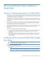
HP Environmental Base Station installed on a CRAH/CRAC............................................................. 25
Overview: Installing a base station on a CRAH/CRAC ................................................................................. 25
Installing the HP Environmental CRAH/CRAC (Single) Base Station ................................................................ 25
Single CRAH installation diagram .................................................................................................... 27
Installing the HP Environmental CRAH/CRAC (Dual) Base Station .................................................................. 28
Dual CRAH installation diagram ...................................................................................................... 30
HP Air Pressure Base Station ........................................................................................................ 31
Overview: Air Pressure Base Station .......................................................................................................... 31
Installing the HP Air Pressure Base Station .................................................................................................. 31
(Optional) Sensor Base Stations .................................................................................................... 34
Overview: (Optional) Sensor base stations ................................................................................................. 34
Installing the HP Door Position Base Station ................................................................................................ 34
Installing the HP Chilled Water Energy Base Station..................................................................................... 36
Single Chilled Water installation diagram......................................................................................... 38
Configuring the Chilled Water Base Station ...................................................................................... 38
Installing the HP Water Leak Detector Base Station ...................................................................................... 46
Water Leak Detector installation diagram ......................................................................................... 49
Installing the HP Current Sensing Relay Base Station .................................................................................... 49
Installing the HP 200A Current Base Station ............................................................................................... 51
200A Current installation diagram .................................................................................................. 54
Installing the HP Energy Base Station ......................................................................................................... 54
Energy Base Station installation diagram .......................................................................................... 57
Programming the ION power meter ................................................................................................. 57
Configuring the Modbus Base Station .............................................................................................. 61
Power up procedure .................................................................................................................... 70
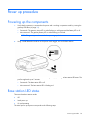
Powering up the components .................................................................................................................... 70
Base station LED status ............................................................................................................................. 70
Troubleshooting .......................................................................................................................... 72
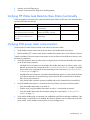
HP Insight Environmental troubleshooting tips .............................................................................................. 72
Power cycle the wireless gateways .................................................................................................. 72
Contents
3
Verifying
Verifying
Verifying
Verifying
Verifying
gateway communication ................................................................................................... 72
network settings ............................................................................................................... 73
HP Water Leak Detection Base Station functionality .............................................................. 74
ION power meter communication ...................................................................................... 74
the CT shorting block position ............................................................................................ 75
Regulatory compliance notices ..................................................................................................... 76
Wireless devices ..................................................................................................................................... 76
Federal Communications Commission notice ............................................................................................... 76
Modifications ................................................................................................................................ 76
FCC Operation Notice ............................................................................................................................. 76
Canadian notices .................................................................................................................................... 76
European Union regulatory notice ............................................................................................................. 77
Brazilian notices ..................................................................................................................................... 78
Japanese notices ..................................................................................................................................... 78
Taiwan notices ........................................................................................................................................ 78
Taiwan battery recycling notice ................................................................................................................. 79
Acronyms and abbreviations ........................................................................................................ 80
Index ......................................................................................................................................... 81
Contents
4
HP Data Center Environmental Edge hardware
overview
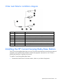
Recommended base configuration
HP recommends the following base configuration for your data center:
•
Two Base Station Gateways for every 400 base stations (A minimum of one base station gateway is
required per wireless network.)
•
One Environmental Base Station and Plenum Rated Sensor Array for every CRAH/CRAC
•
One Environmental Base Station and Rack Sensor Array or Three Point Sensor Array for every three
racks
•
One Air Pressure Base Station for every 50 m2 (500 ft2) of data center floor space
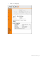
Callout
Component
1
HP Air Pressure Base Station
2
HP Environmental Base Station
3
HP Base Station Gateway
4
HP Rack Sensor Array
5
HP Plenum Rated Sensor Array
6
HP Three Point Sensor Array
Consult your data center administrator for detailed placement and configuration information.
HP Data Center Environmental Edge hardware overview 5
Required tools
The following items are required for installation:
•
HP Environmental Edge Installer Kit
•
Ladder
•
Floor tile suction lifter
•
Perforated floor tile lifter
•
Battery-operated label maker with:
o
Spare batteries
o
Spare ribbon
•
USB barcode scanner
•
Small wire cutting pliers
•
18-30 AWG wire strippers
•
No. 1 Phillips screwdriver
•
1/8-inch standard flathead screwdriver
•
CAT5e Ethernet cable
HP Environmental Edge Installer Kit
The installer kit is provided to ease installation of the hardware components.
NOTE: Most installations do not use all items included in the Mounting Supplies Kit. Do not
discard these items.
The following items are included in the HP Environmental Edge Installer Kit:
•
6-in zip ties (bag of 100)
•
7-in zip ties (bag of 100)
•
Thermistor sensor mounting clips (100)
•
Cable restraint clips
•
Command strips (100)
•
Double-sided tape
•
Mounting tape liner
•
Labels
•
Alcohol wipes
For more information, see the HP Data Center Environmental Edge Installation Kit Information document.
HP Data Center Environmental Edge hardware overview 6
HP Base Station Gateway
Overview: Gateway
The gateway collects information from all wireless base stations within a wireless network and sends the
information to the HP Insight Environmental Observer software over an Ethernet connection.
Only one instance of the HP Insight Environmental Observer software can connect to a gateway device,
though it can connect to multiple gateways within the data center, depending on the available network
connection.
Configuring the HP Base Station Gateway
NOTE: The default IP address for each gateway is 192.168.0.2.
Each installed gateway must have a static IP address. Configure the gateway IP address, using the same
address assigned to the gateway in the HP Insight Environmental Configurator, before you install the
gateway and connect to the network. For more information, see the HP Insight Environmental Configurator
User Guide. Consult your data center administrator to obtain gateway IP addresses.
To configure the gateway:
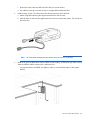
1.
Connect one end of the supplied power cable to the gateway and the other end to a power source.
2.
Connect one end of the CAT5 Ethernet cable to the gateway and the other end to the computer from
which you will configure the gateway.
HP Base Station Gateway
7
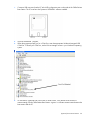
3.
Configure the IP address of the computer to a temporary static address such as 192.168.0.10.
NOTE: You only need to set the IP address to a static address of the configuring computer during
the configuration of the gateway. When you complete the configuration, restore your original
network settings.
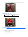
4.
Open your web browser, and in the URL address box, type in the default gateway address:
http://192.168.0.2
The Lantronix Web Manager Login window appears.
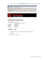
5.
Enter the case-sensitive user name and password.
o
The default user name is admin.
HP Base Station Gateway
8
o
The default password is PASS.
HP Base Station Gateway
9
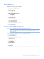
6.
In the navigation menu on left side of the page, select Network. The Network Configuration page
appears.
NOTE: The Ethernet link settings of speed and duplex must match the settings of the switch and
servers NIC. If the speeds or duplex do not match, then the gateway cannot communicate with the
Edge server.
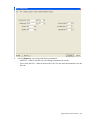
7.
Populate the following fields, using the same information you entered in the HP Insight Environmental
Configurator:
o
IP address (Example: 10.100.100.30)
o
Network mask (Example: 255.255.254.0)
o
Gateway (Example: 10.100.100.1)
8.
Select Submit.
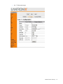
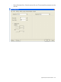
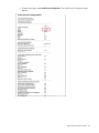
9.
Verify the default settings on the following pages:
HP Base Station Gateway
10
o
Device Status page
HP Base Station Gateway
11
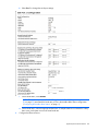
o
Line 1 Configuration page
HP Base Station Gateway
12
o
Tunnel 1 Serial Settings page
HP Base Station Gateway
13
o
Tunnel 1 Accept Mode page
HP Base Station Gateway
14
o
Tunnel 1 Connect Mode page
HP Base Station Gateway
15
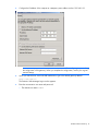
10.
In the navigation menu on the left side of the page, select System. The System page appears.
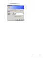
11.
Select Reboot. The confirmation window appears.
12.
Select OK. The gateway reboots, and the new configured parameters take effect.
13.
Repeat steps 1 through 11 for all gateways, using each unique IP address used in the HP Insight
Environmental Configurator.
14.
Restore the original network settings on your computer.
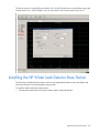
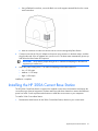
Installing the HP Base Station Gateway
NOTE: Consult your data center administrator to determine the location for the gateway that
optimizes the wireless range for all base stations.
1.
Determine the location for the gateway in your data center.
2.
Ensure the location is free from dust before installing the gateway.
HP Base Station Gateway
16
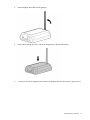
3.
Insert and tighten the antenna to the gateway.
4.
Remove the mounting tape liner, and secure the gateway to the desired location.
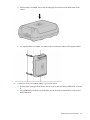
5.
Connect one end of the supplied power cable to the gateway and the other end to a power source.
HP Base Station Gateway
17
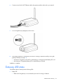
6.
Connect one end of the CAT5 Ethernet cable to the gateway and the other end to your network.
7.
Turn on the gateway by flipping the power switch.
8.
Verify that the gateway is connected to power and is working in operation mode by viewing the
gateway LED status (on page 18).
o
Connected—The gateway Active LED is either flashing or solid green and the Battery LED is off.
o
Not connected—The gateway Battery LED is either flashing or solid red.
Installation is complete.
Gateway LED status
The HP Base Station Gateway has the following LEDs:
•
Battery LED
o
Flashes red if the gateway is not connected to power and is running on batteries.
HP Base Station Gateway
18
o
•
Is solid red if the gateway is not connected to the network or if HP Insight Environmental Observer
application is not running.
Active LED
o
Flashes green if the gateway is communicating and active.
o
Is solid green is the gateway is connected properly and is working in operating mode.
HP Base Station Gateway
19
HP Environmental Base Station installed on a rack
Overview: Installing a base station on a rack
The base station is a wireless device that collects temperature data from the external sensor arrays and sends
the information to the gateway. The base station has its own internal temperature and humidity sensors and
collects data to send to the gateway.
When the base station is installed on a rack, it is attached to either the HP Rack Sensor Array or the HP Three
Point Sensor Array. The base station sends its internal temperature and humidity readings and the external
temperature readings from the sensor arrays to the gateway.
Each sensor array is composed of sensor pods. Each pod has a thermistor that collects temperature data for
a specific location. The sensor array is connected to the HP Environmental Base Station, which collects all
thermistor readings and sends the readings to the gateway.
Two types of sensor arrays can be installed on the rack:
•
HP Rack Sensor Array—The array is composed of six sensor pods. The array is designed for installation
on a rack. Three thermistors are on the front rack door of a cold aisle, and three thermistors are on the
rear rack door of a hot aisle.
•
HP Three Point Sensor Array—The array is composed of three sensor pods. The array is designed for
installation on the front rack door of a cold aisle, hanging from a wall, or installed at the end of a rack
row.
You can install the sensor arrays on the inside of perforated rack doors or the outside of any rack doors. HP
recommends installing the sensor arrays on the inside of the rack doors, if possible.
NOTE: If your rack does not have a door, HP recommends installing the sensor array on the front
left rail of the rack.
NOTE: If you have hot air recirculation issues, then install an HP Three Point Sensor Array at the
end of your rack row to help identify the problem location.
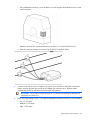
Installing the HP Environmental Base Station on a rack
Installing the HP Rack Sensor Array or HP Three Point Sensor Array
1.
Ensure the rack doors are free from dust before installing the sensor array.
NOTE: The sensor array has labels that indicate the location where the array string must be
installed. Before installation, verify that you are installing the array string to the correct location.
2.
Verify that you are installing the correct sensor string to the correct side of the rack.
HP Environmental Base Station installed on a rack
20
o
The HP Rack Sensor Array has the Front (Cold) Side label and the Rear (Hot) Side label, indicating
where the sensor string is installed.
o
The HP Three Point Sensor Array does not have a label and can be installed anywhere on the rack
or in the data center.
NOTE: The preconfigured lengths between the sensor pods are designed to fit a standard 42U
rack and should be evenly spaced: one at the top of the rack door, one in the middle of the rack
door, and one at the bottom of the rack door. If you are installing the sensor pods on a rack of a
different size and require an extension, consult your data center administrator.
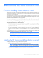
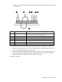
3.
Remove the mounting tape liner and attach the top pod bracket to the designated location. Repeat this
step for the remaining two pod brackets.
4.
If the sensor pod is not connected to the pod bracket, slide the top sensor pod into the pod bracket
installed at the top of the rack door (3). Repeat this step for the remaining two pods.
HP Environmental Base Station installed on a rack
21
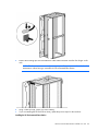
5.
Remove the mounting tape liner and attach the cable restraint brackets near the door hinges on the
rack.
NOTE: The disconnect connector on the sensor array enables you to remove the rack door for
maintenance without having to uninstall the HP Environmental Base Station.
6.
Using a cable tie wrap, secure any excess cabling.
7.
If you are installing the HP Rack Sensor Array, repeat the previous steps for the rear door.
Installing the HP Environmental Base Station
HP Environmental Base Station installed on a rack
22
NOTE: You can install the base station outside or inside of the top of the rack.
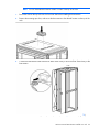
1.
Ensure the area on the top of the rack is free from dust before installing the base station.
2.
Remove the mounting tape liner, and secure the base station to the desired location on the top of the
rack.
3.
Connect the data transfer cable from the HP Rack Sensor Array or HP Three Point Sensor Array to the
base station.
4.
After all hardware is installed, power up the components ("Power up procedure" on page 70).
HP Environmental Base Station installed on a rack
23
Installation is complete.
HP Environmental Base Station installed on a rack
24
HP Environmental Base Station installed on a
CRAH/CRAC
Overview: Installing a base station on a CRAH/CRAC
The base station is a wireless device that collects temperature data from the external sensor arrays and sends
the information to the gateway. The base station also has its own internal temperature and humidity sensors
and collects data of its own to send to the gateway.
When the base station is installed on a CRAH/CRAC, it is attached to the HP Plenum Rated Sensor Array,
and sends its own internal temperature readings and the external temperature reading from the sensor arrays
to the gateway.
The sensor array is composed of sensor pods, each with a thermistor that collects temperature data for a
specific location. The sensor array is connected to the HP Environmental Base Station, which collects the
thermistor readings and sends the readings to the gateway.
The HP Plenum Rated Sensor Array is composed of two sensor pods, one that measures the temperature at the
supply side of the CRAH/CRAC, and one that measures the temperature at the return side of the
CRAH/CRAC.
There are two CRAH/CRAC installation configuration options:
•
Single—(Standard installation configuration) The base station measures temperature and humidity on
the supply side of the CRAH/CRAC and measures only temperature on the return side of the
CRAH/CRAC.
•
Dual—(Optional installation configuration) The base station measures temperature and humidity on
both the supply and return side of the CRAH/CRAC. The return air temperature is an average of six
thermistor readings.
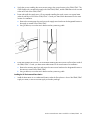
Installing the HP Environmental CRAH/CRAC (Single)
Base Station
WARNING: The CRAH/CRAC must be powered down and the fans must be stopped before you
access the return plenum for hardware installation.
Installing the HP Plenum Rated Sensor Array
1.
Ensure the desired installation locations around the CRAH/CRAC are free of dust before installing the
sensor array.
NOTE: The sensor array has labels that indicate the location where the array string must be
installed. Before installation, verify that you are installing the array string to the correct location.
HP Environmental Base Station installed on a CRAH/CRAC 25
2.
Verify that you are installing the correct sensor string to the correct location in the CRAH/CRAC. The
CRAH Supply side is routed to the supply side of the CRAH/CRAC, and the CRAH Return side is routed
to the return side of the CRAH/CRAC.
3.
Route and install the supply sensor. HP recommends installing the supply sensor to a support beam
under the sub-floor in front of the CRAH/CRAC. Consult your data center administrator for the exact
location for installation.
a. Remove the mounting tape liner and secure the supply sensor bracket to the designated location in
the supply air stream of the CRAH/CRAC.
b. Using a cable tie, secure the sensor bracket and any remaining cable.
4.
Route and install the return sensor. HP recommends installing the return sensor to a flat surface inside of
the CRAH/CRAC. Consult your data center administrator for the exact location for installation.
a. Remove the mounting tape liner and secure the return sensor bracket to the designated location in
the return air stream of the CRAH/CRAC.
b. Using a cable tie, secure the sensor bracket and any remaining cable.
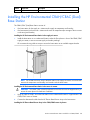
Installing the HP Environmental Base Station
1.
Install the base station in an unobstructed location under the floor plenum in front of the CRAH/CRAC
supply air stream, to ensure accurate supply air humidity readings.
HP Environmental Base Station installed on a CRAH/CRAC 26
HP recommends using cable tie wraps to secure the base station to an available support bracket.
2.
Connect the data transfer cable from the HP Plenum Rated Sensor Array to the base station.
3.
After all hardware is installed, power up the components ("Power up procedure" on page 70).
Installation is complete.
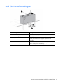
Single CRAH installation diagram
Callout
Component
Description
1
CRAH return air stream
The return air side of the CRAH
2
CRAH supply air stream
The supply air side of the CRAH
3
Base station
The base station is mounted on the supply air side of the CRAH.
4
Supply side of plenum array The three-point plenum array that measures the supply air temperature
and humidity.
5
Return side of plenum array
The three-point plenum array that measures the return air temperature
HP Environmental Base Station installed on a CRAH/CRAC 27
Callout
Component
Description
and humidity.
Installing the HP Environmental CRAH/CRAC (Dual)
Base Station
The CRAH/CRAC (Dual) Base Station consists of:
•
One base station for the supply air—Measures the supply air temperature and humidity
•
One base station for the return air—Measures the return air temperature (the average of the six sensors
on the array) and humidity
Installing the HP Environmental Base Station in the supply air stream
1.
Install the base station in an unobstructed location under the floor plenum in front of the CRAH/CRAC
supply air stream, to ensure accurate supply air humidity readings.
HP recommends using cable tie wraps to secure the base station to an available support bracket.
NOTE: Do not attach a sensor array to the base station in the supply air stream. The sensors that
measure the temperature and humidity are located inside the base station.
Installing the HP Environmental Base Station in the return air stream
WARNING: The CRAH/CRAC must be powered down and the fans must be stopped before you
access the return plenum for hardware installation.
1.
Using the cable tie wraps, secure the base station to an unobstructed location or support beam in the
CRAH/CRAC return air stream.
2.
Connect the data transfer cable from the HP Plenum Rated Sensor Array to the base station.
Installing the HP Plenum Rated Sensor Array in the CRAH/CRAC return air plenum
HP Environmental Base Station installed on a CRAH/CRAC 28
WARNING: The CRAH/CRAC must be powered down and the fans must be stopped before you
access the return plenum for hardware installation.
1.
Ensure the desired installation locations around the CRAH/CRAC are free of dust before installing the
sensor array.
NOTE: During installation of a CRAH/CRAC (dual) base station, ignore the Supply and Return
labels on the sensor array. All six sensors are installed in the return air stream.
2.
Route and install the six sensors to a flat surface inside of the CRAH/CRAC, verifying that the air stream
is not obstructed. Consult your data center administrator for the exact location for installation.
a. Remove the mounting tape liner and secure the return sensor bracket to the designated location in
the return air stream of the CRAH/CRAC.
b. Using a cable tie, secure the sensor bracket and any remaining cable.
After all hardware is installed, power up the components ("Power up procedure" on page 70).
Installation is complete.
HP Environmental Base Station installed on a CRAH/CRAC 29
Dual CRAH installation diagram
Callout
Component
Description
1
CRAH return air stream
The return air side of the CRAH
2
CRAH supply air stream
The supply air side of the CRAH
3
CRAH supply base station
The base station is mounted on the supply air side of the
CRAH, and measures the supply air temperature and
humidity.
4
CRAH return base station and
plenum array
The base station is mounted on the return air side of the CRAH,
and attaches to the six-point plenum array that measures the
return air temperature and humidity.
HP Environmental Base Station installed on a CRAH/CRAC 30
HP Air Pressure Base Station
Overview: Air Pressure Base Station
The air pressure base station is a wireless device that monitors the differential pressure across areas of the
data center and sends the information to the gateway.
The air pressure base station monitors and compares the difference between the pressure below the floor and
the pressure above the floor.
Installing the HP Air Pressure Base Station
1.
Determine the location for the air pressure base station in your data center.
2.
Cut one air tube so that it can reach from the air pressure base station to the area below the floor that
you want to monitor.
3.
Cut the other air tube approximately 7-cm (3-inch) long.
4.
Connect air diffusers to one end of each air tube.
NOTE: To receive accurate air pressure readings, avoid the following locations under the
sub-floor:
• Potentially turbulent air flow
• Support columns or beams
• Water pipes
5.
Install the long air tube. This tube monitors pressure in the desired area below the floor.
a. Attach a flag label indicating the positive terminal to the long air tube.
b. Insert the long air tube into the positive terminal on the air pressure base station.
HP Air Pressure Base Station 31
c.
Route the air tube to the area below the floor that you want to monitor.
d. Use cable tie wraps to secure the air tube to a support bracket below the floor.
6.
Install the short air tube. This tube monitors the reference pressure above the floor.
a. Attach a flag label indicating the negative terminal to the short air tube.
b. Insert the short air tube into the negative terminal on the air pressure base station. The air tube sits
above the floor.
NOTE: HP recommends installing the base station below the floor tile, if possible.
7.
Install the air pressure base station near a subfloor access location, so that the long air tube is routed
under the subfloor and the short air tube is above the floor.
o
If a support bracket is available, use cable tie wraps to secure the base station to the support
bracket.
HP Air Pressure Base Station 32
o
8.
If there is a location behind and under a rack near subfloor access, use the double-sided mounting
tape to secure the air pressure base station to the floor tile near the subfloor access.
After all hardware is installed, power up the components ("Power up procedure" on page 70).
Installation is complete.
HP Air Pressure Base Station 33
(Optional) Sensor Base Stations
Overview: (Optional) Sensor base stations
The optional sensor base stations enable HP approved third-party components to communicate wirelessly to
the gateways. The sensor base stations are considered optional depending on whether you want to monitor
other environmental data in your data center.
The connection between the data center component and the supplied sensor might require professional
installation. However, anyone can perform the installation to connect the sensor to the sensor base station.
You can install any of the following sensor base stations:
•
HP Door Position Base Station—No professional installation required.
•
HP Chilled Water Energy Meter Base Station—Facility technician installation required.
•
HP Water Leak Detection Base Station—Facility technician installation required.
•
HP Current Sensing Relay Base Station—Professional electrician installation required.
•
HP 200A Current Base Station—Professional electrician installation required.
•
HP KWH Base Station—Professional electrician installation required.
You can install the optional sensor base stations on most surfaces using the double-sided mounting tape.
Installing the HP Door Position Base Station
The HP Door Position Base Station connects to the supplied set of door sensors and detects and reports if the
door is open or closed. Ten sensors are located along a 15.2 m (50 ft) wire, which can be installed in a daisy
chain series with one another to monitor multiple doors.
To install a Door Position Base Station:
1.
Ensure the area on the top of the rack is free from dust before installing the base station.
(Optional) Sensor Base Stations
34
2.
Remove the mounting tape liner, and secure the base station to the desired location on the top of the
rack.
3.
Remove the mounting tape liner, and secure the door position wire harness to the rack door.
4.
Connect the Door Position Base Station to the door sensors.
a. Strip the plastic coating from the ends of the two door sensor wires.
b. Strip the plastic coating from the ends of the two wires on the Door Position Base Station wire
harness.
NOTE: If you are only installing one door position sensor, connect the second wire to the Door
Position Base Station. If you are installing the door position sensors in a daisy chain fashion,
connect the second wire to the next door position sensor.
c.
Using a wire screw, twist together one wire from the door sensor with one wire from the Door
Position Base Station wire harness.
Repeat steps a through c for the other wire.
(Optional) Sensor Base Stations
35
d. Insert the connector from the Door Position Base Station wire harness into the Door Position Base
Station.
5.
After all hardware is installed, power up the components ("Power up procedure" on page 70).
Installation is complete.
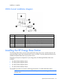
Installing the HP Chilled Water Energy Base Station
The HP Chilled Water Energy Base Station connects to the housing box, which contains an ultrasonic probe
sensor. The ultrasonic sensor measures and reports liquid flow through a chilled water pipe. Temperature
sensors are installed on the supply and return of the same chilled water pipe to measure the rise of the
temperature as chilled water enters and exits the data center room.
Consult a facility technician to install the ultrasonic probe sensor to your chilled water pipe.
To install the Chilled Water Energy Base Station:
1.
Choose a location for the housing box, relatively close to the chilled water pipes.
a. If a flat surface is available, remove the mounting tape liner, and secure the housing box to the
surface.
(Optional) Sensor Base Stations
36
b. If a support bracket is available, use cable ties to secure the housing box to the support bracket.
2.
Route the ultrasonic probe to the appropriate locations along the chilled water pipe.
3.
Connect the housing box to the required sources.
Callout
Component
Description
1
Supply temperature
Routed to the supply side of the chilled water pipe to measure temperature
2
Power connector
Connected to AC power
3
Return temperature
Routed to the return side of the chilled water pipe to measure temperature
4
Downstream flow meter Routed to the downstream of the chilled water pipe to measure flow rate
5
Upstream flow meter
4.
Routed to the upstream of the chilled water pipe to measure flow rate
After all hardware is installed, power up the components ("Power up procedure" on page 70).
Installation is complete.
(Optional) Sensor Base Stations
37
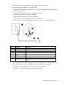
Single Chilled Water installation diagram
Callout
Component
1
Chilled Water Energy Base Station
2
Water supply line to the CRAH/CRAC
3
Water return line from the CRAH/CRAC
4
Water supply temperature sensor probe
5
Upstream flow meter
6
Water return temperature sensor probe
7
Downstream flow meter
Configuring the Chilled Water Base Station
NOTE: You must have the ULTRALINK™ software installed on the PC that is configuring the base
station. You can download the software from the Dynasonics website
(http://www.dynasonics.com/downloads.php).
(Optional) Sensor Base Stations
38
1.
Connect a USB connector from the PC to the USB configuration port on the inside of the Chilled Water
Base Station. The PC must have the Dynasonic ULTRALINK™ software installed.
2.
Open the ULTRALINK™ program.
3.
When the program prompts you for a COM Port, enter the appropriate Windows®-assigned USB
COM Port. To locate your COM Port, see the Device Manager screen in your Windows® operating
system.
4.
On the bottom, right-hand side of the home run mode screen, verify that the USB connector is
communicating with the Chilled Water Base Station. A green OK indicates communication between the
base station and the PC.
(Optional) Sensor Base Stations
39
If a red OFFLINE error appears, select Communications>Initialize, and then re-enter the appropriate
COM port.
(Optional) Sensor Base Stations
40
5.
To configure the Chilled Water Base Station, select Configuration.
The System Configuration window appears.
6.
Select the Basic tab, and configure the following parameters:
o
General—Select the units for the display.
o
Transducer—Select the type, mount, and frequency of the transducer.
o
Pipe—Select the material, diameter, and wall thickness of the pipe.
o
Liner—If a liner is used, select the material and thickness.
(Optional) Sensor Base Stations
41
o
7.
Fluid—Select the type of water.
Select the Flow tab, and configure the following parameters:
o
Flow rate units—Select the measurement rates.
o
Totalizer units—Select the measurement rates.
o
Min flow—Select the minimum flow rate.
o
Max flow—Select the maximum flow rate.
Flow on Data Display
Flow on Data Display
Range
(gpm)
(liters/second)
(liters/second)
up to 475
up to 30
0-30
up to 950
up to 60
0-60
up to 1585
up to 100
0-100
up to 4755
up to 300
0-300
(Optional) Sensor Base Stations
42
8.
Select the Output tab, and configure the following parameters:
o
Module #1—Select the volumetric flow and energy transmitted to the console.
o
Flow at 4mA (Min flow)—Select the minimum flow rate. This must match the parameters set on the
Flow tab.
(Optional) Sensor Base Stations
43
o
Flow at 20mA (Max flow)—Select the maximum flow rate. This must match the parameters set on the
Flow tab.
(Optional) Sensor Base Stations
44
9.
Select the Basic tab, and then select Download to transfer the new settings into the Chilled Water Base
Station.
10.
Select OK to save the configuration settings and close the System Configuration window.
Testing the configuration
The 4mA and 20mA calibration values are factory set and must not be modified. If you modify these
calibration values and select Download, you will override the 4-20mA factory preset.
You can test the analog flow meter output for troubleshooting purposes. The Test field represents the Flow
Meter 4-20mA analog output value, but not the flow rate. The minimum value is 4 and the maximum value
is 20.
NOTE: Do not select Download during the testing or calibration process.
To test the calibration:
1.
Select the Calibration/Test box. The Calibration and Test fields are now active.
2.
Using whole numbers, adjust the Test field.
3.
Verify the flow rate on the console matches the calibration of your flow rate.
Example:
(Optional) Sensor Base Stations
45
The flow at 4mA is 0 l/s and the flow at 20mA is 30 l/s. If the Test field is set to 4, then the flow rate on the
console must be 0 l/s. If the Test field is set to 20, then the flow rate on the console must be 30 l/s.
Installing the HP Water Leak Detector Base Station
The HP Water Leak Detector Base Station connects to the supplied leak detector sensor and detects and
reports the presence of any fluid along the sensing cable.
To install the Water Leak Detector Base Station:
1.
Determine the ideal location for the base station and the water leak detector.
(Optional) Sensor Base Stations
46
2.
If a support bracket is available, use cable ties to secure both the base station (1) and the water leak
detector (2) to the support bracket.
3.
Connect the leak detector sensing cable assembly to the Water Leak Detector.
a. Cut approximately 5-cm (2-inch) of wire from the end of the wire harness.
b. Strip the plastic coating from the ends of the wire you just cut to create a jumper wire.
c.
Strip the plastic coating from the two wire pairs on the wire harness.
d. Strip the plastic coating from the white jumper cable to expose four colored wires.
e. Using the supplied Allen wrench, loosen the two screws on the ends of the Water Leak Detector to
remove the lid.
f.
Using a flathead screwdriver, loosen the four screws on the CABLE INPUT terminal block.
i.
Insert and tighten the green wire in the G terminal.
ii. Insert and tighten the red wire in the R terminal.
iii. Insert and tighten the white wire in the W terminal.
iv. Insert and tighten the blue wire in the B terminal.
g. Loosen the C terminals on the LEAK terminal block and the FAULT terminal block.
i.
Insert and tighten the non-labeled white wire from the wire harness in the LEAK terminal block.
ii. Insert and tighten the non-labeled black wire from the wire harness in the FAULT terminal block.
h. Loosen the NC terminals on the leak terminal block and the fault terminal block.
i.
Insert and tighten one end of the jumper wire in each NC terminal.
j.
Loosen the + (positive) and - (negative) contact screws in the 5V DC IN terminal block.
i.
Insert and tighten the white wire labeled 5V from the wire harness in the + (positive) terminal.
ii. Insert and tighten the black wire labeled 5V from the wire harness in the - (negative) terminal.
(Optional) Sensor Base Stations
47
k. Replace the Water Leak Detector lid, and use the supplied Allen wrench to tighten the two screws to
secure the lid.
Callout
Component
Description
1
5VDC IN
Insert the white wire into the + (positive) terminal.
Insert the black wire into the - (negative) terminal.
2
Fault and Leak
3
W terminal
Insert the white wire from the wire harness.
4
B terminal
Insert the black wire from the wire harness.
5
G terminal
Insert the green wire from the wire harness.
6
R terminal
Insert the red wire from the wire harness.
7
NC jumper wire
Connect the Fault and Leak terminals.
4.
Insert the leak detection cable in to the water leak detector sensor and tighten the connector.
5.
Route the sensing cable along the sub-floor, in strategic locations, to detect the presence of fluid.
6.
Connect the Water Leak Detector to the base station.
7.
Connect one end of the AC adapter to the power input connector on the Water Leak Detector wire
harness, and then plug the other end of the AC adapter into a power source. The base station
automatically powers up and follows the Base Station LED sequence.
Installation is complete.
(Optional) Sensor Base Stations
48
Water Leak Detector installation diagram
Callout
Component
Description
1
AC adapter
Plugs into a power source
2
Base station
Wirelessly transmits information to the Edge server
3
Connection point
Connects the base station to the water leak detector
4
Water leak detector
Processes the detection of fluid
5
Connection point
Connects the water leak detector to the jumper cable
6
Jumper cable
Connects the sensing cable to the water leak detector
7
Connector
Connects the jumper cable to the sensing cable assembly
8
Sensing cable assembly
Detects any fluid
Installing the HP Current Sensing Relay Base Station
The HP Current Sensing Relay Base Station uses one CT to measure and report the current flowing to electrical
equipment, and is typically used to determine whether the equipment is powered on or off. Consult a
professional electrician to install the current sensor.
To install a Current Sensing Relay Base Station:
1.
Determine the ideal location for the base station, relative to your electrical equipment.
(Optional) Sensor Base Stations
49
a. If a flat surface is available, remove the mounting tape liner and secure the base station to the
surface.
b. If a support bracket is available, use cable ties to secure the base station to the support bracket.
2.
Connect the Current Sensing Relay Base Station to your current sensor.
a. Strip the plastic coating from the ends of the two wires on the wire harness labeled CH 3.
b. Using a flathead screwdriver, secure the white wire to the positive terminal block on the current
sensor transducer.
(Optional) Sensor Base Stations
50
c.
Using a flathead screwdriver, secure the black wire to the negative terminal block on the current
sensor transducer.
d. Insert the connector from the wire harness into the Current Sensing Relay Base Station.
3.
Connect one end of the 24V AC adapter to the power input connector on the base station, and then
plug the other end of the AC adapter into a power source. The base station automatically powers up
and follows the Base Station LED sequence.
IMPORTANT: Verify that the jumper setting of the CT matches the amperage of the electrical
equipment you connect it to.
4.
Adjust the jumper setting of the CT to match the amperage of the electrical device.
o
Low—O-100 amps
o
Medium—0-150 amps
o
High—0-200 amps
Installation is complete.
Installing the HP 200A Current Base Station
The HP 200A Current Base Station connects to the supplied current sensor and measures and reports the
current flowing to electrical equipment. The base station provides three channels to monitor three different
power line feeds. Consult a professional electrician to install the current sensor to your component.
To install a 200A Current Base Station:
1.
Determine the ideal location for the 200A Current Base Station, relative to your current sensor.
(Optional) Sensor Base Stations
51
a. If a flat surface is available, remove the mounting tape liner and secure the base station to the
surface.
b. If a support bracket is available, use cable ties to secure the base station to the support bracket.
2.
Connect the 200A Current Base Station to your current sensor.
a. Strip the plastic coating from the ends of the two wires on the wire harness labeled CH 3/Current
A.
b. Using a flathead screwdriver, secure the white wire to the positive terminal block on the current
sensor transducer.
(Optional) Sensor Base Stations
52
c.
Using a flathead screwdriver, secure the black wire to the negative terminal block on the current
sensor transducer.
Repeat for the other two current transducers (CH 4 and CH 5/Current B and Current C).
d. Insert the connector from the wire harness into the 200A Current Base Station.
3.
Connect one end of the 24V AC adapter to the power input connector on the 200A Current Base
Station, and then plug the other end of the AC adapter into a power source. The base station
automatically powers up and follows the Base Station LED sequence.
IMPORTANT: Verify that the jumper setting of the CT matches the amperage of the electrical
equipment you connect it to.
4.
Adjust the jumper setting of each CT to match the amperage of the electrical device it is connected to.
o
Low—O-100 amps
o
Medium—0-150 amps
o
High—0-200 amps
(Optional) Sensor Base Stations
53
Installation is complete.
200A Current installation diagram
Callout
Component
Description
1
Power device
Any power component whose power current you want to measure
2
CH3, CH4, and CH5 CTs Three separate current transducer channels to measure three current lines
3
Current lines
Three separate current lines measured by the CTs
4
Connection point
Low voltage wires connecting the CTs to the base station
5
Base station
Wirelessly transmits information to the Edge server
6
AC adapter
Plugs into a power source
7
Connector
Connects the base station to the AC adapter
Installing the HP Energy Base Station
The HP Energy Base Station connects to the supplied ION energy meter sensor, and then measures and
reports the energy usage of the monitored power source or location. Consult a professional electrician to
install the ION power meter sensor to your power source.
Depending on the power configuration of your energy meter, the following KWH Base Stations are
available:
•
HP 208V/200A KWH Base Station
•
HP 208V/600A KWH Base Station
•
HP 480V/200A KWH Base Station
•
HP 480V/600A KWH Base Station
The installation procedure is the same for all Energy base stations. To install a KWH base station:
NOTE: A licensed electrician must install the ION power meters to the designated locations of
the data center.
(Optional) Sensor Base Stations
54
1.
Choose the location for the Energy Base Station, relative to your energy meter.
2.
Connect the Energy Base Station to your energy meter.
a. Strip the plastic coating from the ends of the two wires on the Energy Base Station wire harness.
b. Open the energy meter.
c.
Using a small screwdriver, loosen the 1K and COM terminals.
d. Insert the end of the red wire into the 1K terminal.
e. Insert the end of the black wire into the COM terminal.
f.
Using a small screwdriver, tighten the 1K and COM terminals.
g. Insert the connector from the Energy Base Station wire harness into the Energy Base Station.
Callout
Component
Description
1
Energy meter
Meter wiring terminal blocks
2
RS-485 (+ terminal)
Insert the red wire from the wire harness.
3
RS-485 (- terminal)
Insert the black wire from the wire harness.
4
RS-485 (ground/shield)
Insert the silver wire from the wire harness.
5
Installed on the last meter of a RS-485 daisy chain
6
RS-485 bus terminating
resistor
RS-485 cable
7
Modbus base station
Communicates data from the energy meter to the Edge server via
Ethernet
Connects the ION meter to the Modbus base station
3.
Using an RS-485 cable, connect the ION power meters in a daisy chain to the Modbus base station.
4.
Using an Ethernet cable, connect the Modbus base station to the Edge server network.
Verify that the pins of the adapter are connected in the correct orientation:
o
RS-485 (+): Pin 1 (RJ-45 connector) to Pin 7 (RS-232 connector)
(Optional) Sensor Base Stations
55
o
RS-485 (-): Pin 4 (RJ-45 connector) to Pin 3 (RS-232 connector)
Callout
Component
Description
1
RJ-45 Ethernet connector
Component of the Modbus adapter
2
RS-232 connector
Component of the Modbus adapter
3
A/C power connector
Connects to the power source
4
CAT5 Ethernet connector
Connects to the network
5
Modbus adapter (RJ-45 to Connects the RJ-45 connector to the RS-232 connector
RS-232)
RS-485 cable
Connects the energy meter to the Modbus base station
6
5.
Verify that the ION power meters are configured and meet all requirements.
6.
After all hardware is installed, power up the components ("Power up procedure" on page 70).
Installation is complete.
(Optional) Sensor Base Stations
56
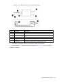
Energy Base Station installation diagram
Callout
Component
Description
1
Energy meter
Energy meter(with housing case removed) you want to measure
2
RS-485 (+ terminal)
RS-485 (+)
3
RS-485 (- terminal)
RS-485 (-)
4
RS-485 (ground/shield)
RS-485 (ground wire)
5
RS-485 bus terminating
resistor
If a single energy meter is connected to the Modbus base station, the
terminating resistor must be installed.
If multiple energy meters are connected to the Modbus base station,
in a daisy chain, the terminating resistor is installed only on the last
energy meter.
6
RS-485 wire
RS-485 wire routed from the energy meter to the Modbus base station
7
Modbus base station
Transmits data from the energy meter to the Edge server via Ethernet
8
RJ-45 Ethernet connector
Connects to Ethernet network
9
AC power connector
Connects to power source
10
Modbus adapter (RJ-45 to
DB-9)
Connection point between the energy meter and the Modbus base
station
Programming the ION power meter
You must be standing at the ION power meter to program the device. It is not capable of remote
programming.
1.
Press and hold the UP and DOWN arrows simultaneously for a minimum of 2 seconds to access the
programming mode.
2.
Press the KVARh button to scroll through the available modes.
3.
Press and hold the UP or DOWN arrow for a minimum of 2 seconds to move from digit to digit when
adjusting values.
(Optional) Sensor Base Stations
57
4.
Press and hold the UP and DOWN arrows simultaneously for a minimum of 2 seconds to exit.
Programming the voltage mode
Set the Volts Mode type according to the specific power connection type.
Power connection type
ION setting
4wire wye (4 wire, 3 phases + neutral)
4W
Direct Delta (3 wire, 3 phases, no neutral)
dELd
Programming the CT model
NOTE: All of the CTs must have the same ratings.
Set the primary and secondary transducer values:
•
Primary transducer type—Ct1
•
Secondary transducer type—Ct2
An example of a 200A CT is:
(Optional) Sensor Base Stations
58
•
Ct1 = 200
•
Ct2 = 5
Programming the digital out
1.
Set the following values.
Digital out
ION setting
out1
wh
0.5
Tc1
NOTE: You cannot verify the CT polarity if you are in the Direct Delta voltage mode. To verify the
CT polarity, temporarily switch the meter to 4W mode. After the polarity is verified, switch back to
dELd mode. For more information, see Programming the voltage mode (on page 58).
2.
Verify the CT polarity by reading the current phase values.
If the polarity is backwards, then the - light is on for each CT. Return to the programming mode and
change CPL1, CPL2, and CPL3 to inv. The polarity is automatically reversed, as if you reversed the
black and white wires.
Programming Modbus communication
The ION6200 Energy Meter supports 2wire with shielded RS-485 connection. You can connect multiple
meters (up to 32) in a daisy chain series, in which case, the last meter of the series must have the terminating
resistor installed. For more information, see Installing the HP 480V/200A-600A Energy Base Station.
Programming the Modbus ID
1.
Set the protocol to Modbus (Mod).
NOTE: The Modbus ID is default to 1xx, where the xx is the last two digits of the unit serial
number.
(Optional) Sensor Base Stations
59
2.
Set the device unit ID to a number value between 1 and 32. If multiple meters are connected in a daisy
chain series, each meter must have a unique device unit ID.
NOTE: The baud rate you set on the ION Energy Meter Modbus ID ("Programming the Modbus
ID" on page 59) must match the baud rate you set in the Modbus Base Station configuration
("Configuring the Modbus Base Station" on page 61).
3.
Set the serial baud rate to 19.2K.
(Optional) Sensor Base Stations
60
4.
Set the power scale (PPS) to 10x.
Configuring the Modbus Base Station
1.
Go to the Comtrol website (http://www.comtrol.com), download and install Port Vision Plus software.
Port Vision Plus software is used to locate, configure, and manage DeviceMasters over a network.
2.
Select the Scan button to discover the Modbus base station.
(Optional) Sensor Base Stations
61
The Scan results appear.
3.
Right-click the Modbus base station you want to configure and select Web Manager.
(Optional) Sensor Base Stations
62
The main Comtrol Web Manager main page appears.
4.
Configure the device network settings.
(Optional) Sensor Base Stations
63
a. From the main page, select Configure Network. The Edit Network Configuration page appears.
b. Enter the IP address properties, as provided by the network administrator.
c.
5.
Select Save.
Configure device serial settings.
(Optional) Sensor Base Stations
64
a. From the main page, select Serial Device Configuration. The Serial Device Configuration page
appears.
(Optional) Sensor Base Stations
65
b. Select Port 1 to change the serial port settings.
c.
On the Mode menu, select RS-485.
NOTE: The baud rate you set on the ION Energy Meter Modbus ID ("Programming the Modbus
ID" on page 59) must match the baud rate you set in the Modbus Base Station configuration
("Configuring the Modbus Base Station" on page 61).
d. On the Baud menu, select the appropriate baud rate. If multiple meters are connected in a daisy
chain series, each meter must use the same baud rate.
6.
Configure the Ethernet Device.
(Optional) Sensor Base Stations
66
a. From the main page, select Ethernet Device Configuration. The Ethernet Device Configuration page
appears.
(Optional) Sensor Base Stations
67
b. Select Socket 1. The Edit Socket Port 1 Configuration page appears.
(Optional) Sensor Base Stations
68
7.
From the main page, select Reboot to update all new configurations.
(Optional) Sensor Base Stations
69
Power up procedure
Powering up the components
1.
Verify that the gateway is connected to the power and is working in operation mode by viewing the
gateway LED status (on page 18).
o
Connected—The gateway Active LED is either flashing or solid green and the Battery LED is off.
o
Not connected—The gateway Battery LED is either flashing or solid red.
NOTE: The gateway must be active before powering up the base stations.
2.
Using a small flathead screwdriver or the power switch toggle, turn on the base stations.
3.
Verify that all base stations have connected to the gateway by viewing the base station LED status. This
process might take up to 5 minutes.
o
Connected—The base station LED is off.
o
Not connected—The base station LED is flashing red.
Base station LED status
There are three base station modes:
•
Off
•
Initial power up
•
On and operating
The initial power up sequence corresponds to the following steps:
Power up procedure
70
1.
During the initial power up mode and after the initial bootup LED sequence, the LED on the base station
flashes red while attempting to find and connect to the gateway.
2.
When the base station is connected, the LED flashes green indicating that it is communicating with the
gateway.
3.
When the base station is identified by the gateway, it stops flashing and begins working in operating
mode. The LED on the base station is off.
The initial power up mode only lasts approximately 5 to 10 minutes.
•
If the LED is still flashing red after 10 minutes:
o
Verify that the gateway is powered up and connected to the network.
o
Verify that all the HP Insight Environmental Observer software components are installed and running
properly.
•
If the LED is still flashing green after 10 minutes, verify that the deployment lab configuration was
properly exported.
•
If the LED is flashing yellow, the base station is not in the correct operating mode. Toggle the power
button three times, (On, Off, On, Off, On) with a maximum of 1 to 2 seconds between each toggle.
Power up procedure
71
Troubleshooting
HP Insight Environmental troubleshooting tips
To troubleshoot communication issues:
1.
Turn off all of the wireless base stations in the data center.
2.
Power cycle each of the wireless gateways ("Power cycle the wireless gateways" on page 72).
3.
From the server, turn off the HP Insight Environmental Device Manager component.
4.
Verify that each of the gateways are communicating ("Verifying gateway communication" on page
72).
5.
From the server, restart the HP Insight Environmental Device Manager component.
6.
Turn on each of the wireless base stations, and verify that they join the wireless network within ten
minutes.
7.
From the server, use the HP Insight Environmental Observer software to verify that the wireless base
stations are reporting sensor data.
8.
Turn on all remaining wireless base stations.
Power cycle the wireless gateways
1.
Turn the gateway off then back on again.
2.
Verify that green (ACT) LED and the Ethernet port LEDs are blinking.
3.
If the LEDs are not blinking when the gateway is turned on, power cycle twice, turning the gateway off,
on, off, on, with a one second pause in between each cycle.
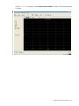
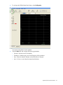
Verifying gateway communication
1.
From the server, enter the following Windows® command prompt:
telnet <IP address of the HP base station gateway> 10001
2.
o
If special characters are scrolling across the screen, the gateway is properly configured and
communicating with the server.
o
If special characters are not scrolling across the screen, verify that port 10001 is not blocked on the
network port or for the gateway static IP address.
Repeat step 1 for all wireless gateways.
Troubleshooting
72
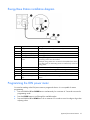
Use the following flow chart to help troubleshoot gateway communication errors and determine whether you
must replace the gateway.
Verifying network settings
You must set network and Ethernet settings in three separate locations. Both the Ethernet Speed and Ethernet
Duplex must be set to Auto and must match in each of the three locations:
•
Network Configuration of the HP Base Station Gateway
Troubleshooting
73
•
Network card on the Edge server
•
Network switch between the Edge server and the gateway
Verifying HP Water Leak Detection Base Station functionality
When verifying the functionality of the water leak detector base station, the LED status must match the status
reported in the Observer software.
LED status
Observer status
Meaning
Solid light
Status icon is green
(normal status)
Status icon is ____
(water leak condition is active)
No alarms present
Flashing
(on 1/2 second, off 1/2 second)
Flashing
(on 1/2 second, off 2 and 1/2
seconds)
Status icon is red
(alarm status)
Leak alarm
Cable break alarm
Verifying ION power meter communication
Communication from the ION power meter to the Observer software includes:
•
Serial Modbus communication from the power meter to the Modbus base station device
•
Ethernet Modbus/TCP communication from the Modbus base station device to the Observer software
To make sure that the ION power meters communicate correctly with the server and Observer software, verify
the following connections.
•
•
•
Verify the ION power meters (in a daisy chain configuration) are connected to the Modbus base station
via an RS-485 serial connection.
o
If multiple ION power meters are connected to the Modbus base station (in a daisy chain), verify
that each power meter has a unique device ID ("Programming the Modbus ID" on page 59) and that
the last meter in the configuration has the terminating resistor connected ("Programming Modbus
communication" on page 59).
o
If multiple ION power meters are connected to the Modbus base station (in a daisy chain) and some
of the power meters are not communicating, verify that the RS-485 connections down the daisy
chain are securely connected.
o
Verify that all cable connection points are installed and securely fastened to the terminal block.
Verify the Modbus base station is connected to the server network connection via Ethernet cable.
o
Verify the Modbus base station is powered on.
o
From the server, ping the Modbus base station to verify it is connected to the network.
o
Verify the Modbus base station has the duplex setting set to Auto Duplex ("Verifying network
settings" on page 73).
Verify that the Modbus plug in component was installed during the Device Manager installation. If the
Modbus plug in component was not installed, the Observer software cannot communicate to the ION
power meters, and no Modbus communication occurs to the Edge server.
Troubleshooting
74
Verifying the CT shorting block position
If the CT values for your ION power meter all appear to be zero, a CT shorting block might be in the down
(installation) position. Verify that all of the shorting blocks are in the up (operating) position.
Troubleshooting
75
Regulatory compliance notices
Wireless devices
You can install one or more integrated wireless devices. In some environments, the use of wireless devices
might be restricted. Such restrictions might apply on airplanes, in hospitals, near explosives, or in other
hazardous locations. Before you turn on this product, be sure that you understand local policies and have
proper authorization.
Do not co-locate or operate this device in conjunction with any other antenna or transmitter.
To avoid the possibility of exceeding the FCC radio frequency exposure limits, human proximity to the
antennae should be greater than 20 cm (8 in).
WARNING: Exposure to Radio Frequency Radiation—The radiated output power of this device
is below the FCC radio frequency exposure limits. Nevertheless, human contact during normal
operation should be minimized.
Federal Communications Commission notice
This equipment has been tested and found to comply with the limits for a Class A digital device, pursuant to
Part 15 of the FCC Rules. These limits are designed to provide reasonable protection against harmful
interference when the equipment is operated in a commercial environment. This equipment generates, uses,
and can radiate radio frequency energy and, if not installed and used in accordance with the instructions,
may cause harmful interference to radio communications. Operation of this equipment in a residential area
is likely to cause harmful interference, in which case the user will be required to correct the interference at
personal expense.
Modifications
The FCC requires the user to be notified that any changes or modifications made to this device that are not
expressly approved by Hewlett-Packard Company may void the user’s authority to operate the equipment.
FCC Operation Notice
This device complies with Part 15 of the FCC Rules. Operation is subject to the following two conditions: (1)
this device may not cause harmful interference, and (2) this device must accept any interference received,
including interference that may cause undesired operation.
Canadian notices
Wireless operation is subject to two conditions. The first is that the wireless device may not cause
interference. The second is that the wireless device must accept any interference, including interference that
may cause undesired operation of the device.
Regulatory compliance notices
76
European Union regulatory notice
Products bearing the CE marking comply with the following EU Directives:
•
Low Voltage Directive 2006/95/EC
•
EMC Directive 2004/108/EC
•
Ecodesign Directive 2009/125/EC, where applicable
CE compliance of this product is valid if powered with the correct CE-marked AC adapter provided by HP.
If this product has wired and/or wireless telecommunications functionality, it also complies with the essential
requirements of the following EU Directive:
•
R&TTE Directive 1999/5/EC
Compliance with these directives implies conformity to the applicable harmonized European standards
(European Norms) that are listed in the EU Declaration of Conformity issued by HP for this product or product
family and available (in English only) either within the product documentation or at the following HP website
(http://www.hp.eu/certificates) (type the product number in the search field).
The compliance is indicated by one of the following conformity markings placed on the product:
For non-telecommunications products and for EU harmonized telecommunications products, such as
Bluetooth® within power class below 10mW.
For EU non-harmonized telecommunications products (If applicable, a 4-digit notified body number is
inserted between CE and !).
Please refer to the regulatory label provided on the product.
The telecommunications functionality of this product may be used in the following EU and EFTA countries:
Austria, Belgium, Bulgaria, Cyprus, Czech Republic, Denmark, Estonia, Finland, France, Germany, Greece,
Hungary, Iceland, Ireland, Italy, Latvia, Liechtenstein, Lithuania, Luxembourg, Malta, Netherlands, Norway,
Poland, Portugal, Romania, Slovak Republic, Slovenia, Spain, Sweden, Switzerland, and United Kingdom.
The telephone connector (not available for all products) is intended for connection to analogue telephone
networks.
Products with wireless LAN devices:
Some countries may have specific obligations or special requirements about the operation of Wireless LAN
networks such as indoor use only or restrictions of the channels available. Please make sure that the country
settings of the wireless network are correct.
France:
For 2.4 GHz Wireless LAN operation of this product, certain restrictions apply: This product may be used
indoors for the entire 2400-MHz to 2483.5-MHz frequency band (channels 1 to 13). For outdoor use, only
the 2400-MHz to 2454-MHz frequency band (channels 1 to 7) may be used. For the latest requirements, see
the ARCEP website (http://www.arcep.fr) http://www.arcep.fr.
Regulatory compliance notices
77
The point of contact for regulatory matters is Hewlett-Packard GmbH, Dept./MS: HQ-TRE, Herrenberger
Strasse 140, 71034 Boeblingen, GERMANY.
Brazilian notices
Este equipamento opera em caráter secundário, isto é, não tem direito a proteção contra interferência
prejudicial, mesmo de estações do mesmo tipo, e não pode causar interferência a sistemas operando em
caráter primário.
Japanese notices
Taiwan notices
Batteries, battery packs, and accumulators should not be disposed of together with the general
household waste. To forward them to recycling or proper disposal, use the public collection system or
return them to HP, an authorized HP Partner, or their agents.
Regulatory compliance notices
78
For more information about battery replacement or proper disposal, contact an authorized reseller or an
authorized service provider.
Taiwan battery recycling notice
The Taiwan EPA requires dry battery manufacturing or importing firms in accordance with Article 15 of the
Waste Disposal Act to indicate the recovery marks on the batteries used in sales, giveaway or promotion.
Contact a qualified Taiwanese recycler for proper battery disposal.
Regulatory compliance notices
79
Acronyms and abbreviations
CRAC
computer room air conditioning
CRAH
computer room air handler
CT
current transducer
LED
light-emitting diode
PDU
power distribution unit
Acronyms and abbreviations 80
Index
A
G
air pressure base station, installation 31
air pressure base station, overview 31
gateway, communication 72
gateway, configuring 7
gateway, installing 16
gateway, LED status 18
gateway, overview 7
gateway, power cycle 72
B
base configuration 5
base station, CRAH/CRAC overview 25
base station, dual CRAH/CRAC installation 28, 30
base station, LED status 70
base station, rack installation 20
base station, rack overview 20
base station, single CRAH/CRAC installation 25, 27
battery disposal 78
Brazilian notice 78
C
Canadian notice 76
Chilled Water Base Station, configuring 38, 45
configuring the Chilled Water Base Station 38, 45
configuring the gateway 7
configuring the Modbus Base Station 61
CT shorting block 75
H
HP 200A Current Base Station 51, 54
HP Air Pressure Base Station 31
HP Base Station Gateway 7
HP Chilled Water Energy Base Station 36
HP Current Sensing Relay Base Station 49
HP Door Position Base Station 34
HP Energy Base Station 54
HP Environmental Base Station, CRAH/CRAC 25
HP Environmental Base Station, rack 20
HP Water Leak Detector Base Station 46, 49
I
European Union regulatory notice 77
installer kit 6
installing the air pressure base station 31
installing the base station on a CRAH/CRAC 28
installing the base station on a rack 20
installing the gateway 16
installing the HP 200A Current Base Station 51, 54
installing the HP Chilled Water Energy Base
Station 36
installing the HP Current Sensing Relay Base
Station 49
installing the HP Door Position Base Station 34
installing the HP Water Leak Detector Base
Station 46, 49
F
J
Federal Communications Commission (FCC)
notice 76
Japanese notice 78
D
diagram, 200A current base station installation 54
diagram, chilled water installation 38
diagram, dual CRAH/CRAC installation 30
diagram, energy base station installation 57
diagram, single CRAH/CRAC installation 27
diagram, water leak detector installation 49
E
L
LED status, gateway 18
Index
81
M
wireless devices 76, 78
Modbus Base Station, configuring 61
modifications, FCC notice 76
N
network settings 73
notices 2
O
overview 5
P
power cycle gateways 72
power meter, programming 57, 58, 59
power up procedure 70
powering up the components 70
programming the power meter 57, 58, 59
programming, CT model 58
programming, digital out 59
programming, Modbus communication 59
programming, Modbus ID 59
programming, voltage mode 58
R
recommended configuration 5
regulatory compliance notices 76
required tools 6
S
sensor base stations 34
sensor base stations, overview 34
T
Taiwan battery recycling notice 79
Taiwan notice 78
troubleshooting 72
V
verifying
verifying
verifying
verifying
communication 74
CT shorting block position 75
functionality 74
network 73
W
water leak detector functionality 74
Index
82