1
Installation and
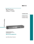
Reference Guide
HP J2611B
HP AdvanceStack 10Base-T Hub-16U
Perforate
HP Customer Support Services
How to get the latest software/agent firmware
You can download:
HP AdvanceStack 8U/16U SNMP firmware:
j3133a.exe
from the HP BBS, HP FTP Library Service, CompuServe, and the World Wide
Web. After you download the file, extract the file by typing filename /x. For
example j3133a.exe /x
HP BBS
Set your modem to N-8-1, set speed up to 14400 bps, and with your telecommunication program (e.g., Windows Terminal) dial (208) 344-1691 to get the
latest software for your HP networking product.
HP FTP Library Service
1) FTP to Internet IP Address - ftp-boi.external.hp.com
2) Log in as anonymous and press [Return] at the password prompt.
3) Enter bin to set the transfer type.
4) Enter cd /pub/networking/software
5) Enter get filename to transfer the file to your computer and quit.
CompuServe
1) Login to CompuServe.
2) Enter go hpsys
3) Enter lib 7
4) Enter download filename and then quit.
World Wide Web
http://www.hp.com/go/network_city
Select the“ Support” section, then “Software Downloads and Patches”.
Download the file you need and extract it by typing: filename /x
Do you have questions about designing your expanding network? From this
web site, you can also download the Designing HP AdvanceStack Workgroups Networks Guide which addresses capacity planning or dial
1-800-752-0900 to receive a copy through the mail.
Obtain the latest agent firmware (j3133a.exe)
from:
HP FTP Library:
ftp ftp-boi.external.hp.com
World Wide Web:
http://www.hp.com/go/network_city
HP BBS
(208) 344-1691
CompuServe
go hpsys
lib 7
download j3133a.exe
Perforate
Perforate
Perforate
Perforate
✁
HP AdvanceStack Hub-16U
Installation and Reference Guide
©Copyright Hewlett-Packard Company 1996
All Rights Reserved.
Reproduction, adaptation, or translation without
prior written permission is prohibited, except as
allowed under the copyright laws.
Publication Number
J2611-90101
Edition 1
February 1996
Applicable Product
HP J2611B
Trademark Credits
MS-DOS® and Microsoft® are U.S. registered
trademarks of Microsoft Corporation.
Ethernet is a registered trademark of Xerox
Corporation.
Disclaimer
The information contained in this document is
subject to change without notice.
HEWLETT-PACKARD COMPANY MAKES NO
WARRANTY OF ANY KIND WITH REGARD TO
THIS MATERIAL, INCLUDING, BUT NOT
LIMITED TO, THE IMPLIED WARRANTIES OF
MERCHANTABILITY AND FITNESS FOR A
PARTICULAR PURPOSE. Hewlett-Packard shall
not be liable for errors contained herein or for
incidental or consequential damages in
connection with the furnishing, performance, or
use of this material.
Hewlett-Packard assumes no responsibility for
the use or reliability of its software on
equipment that is not furnished by
Hewlett-Packard.
Warranty
See the warranty statement and the registration
form included with the product.
A copy of the specific warranty terms applicable
to your Hewlett-Packard product and
replacement parts can be obtained from your HP
Sales and Service Office or authorized dealer.
8000 Foothills Boulevard
Roseville, California 95747-5551
http://www.hp.com/go/network_city
HP AdvanceStack Hub-16U
At A Glance
The HP J2611B AdvanceStack Hub-16U is a multiport repeater with 16
twisted-pair network ports. With this hub, you can connect computers and
other devices together in an unshielded twisted-pair cable network. The hub
is compliant with the IEEE 802.3 Type 10Base-T standard and supports both
802.3 and Ethernet networks.
iii
Front of the Hub
Hub status
LEDs
MDI/MDI-X switch
for port 16
Cover plate over slot for HP AUI and
Transceiver Modules
Twisted-pair
port LEDs
Twisted-pair
ports
Back of the Hub
ac power
receptacle
iv
Cover plate over slot for
HP AdvanceStack 8U/16U SNMP Module
Features
Network Connections
16 RJ-45 (twisted-pair) ports to connect to end nodes or other devices.
A Media Dependent Interface (MDI) switch for Port 16 which allows you to
connect either an end node (MDI-X position) or to cascade a hub (MDI position)
to the port, using a “straight-through” twisted-pair cable in both cases.
Upgradeable Design
A management slot in the back of the hub enables you to install an HP
AdvanceStack 8U/16U SNMP Module. With the module, you can serially
connect an ASCII console to the module to configure, monitor, and troubleshoot
the hub.
An AUI/Xcvr Slot in the front of the hub for several types of transceiver modules
including ThinLAN, AUI, twisted-pair, and fiber-optic. With the optional ThinLAN
transceiver, you can “hot-swap” a hub. Hot-swap means that removing a hub
connected to other hubs through the ThinLAN transceiver does not bring down
the network; you can upgrade or replace hubs in a stack with the network up
and running. All modules with an external transceiver allow you to connect to
an Ethernet/IEEE 802.3 LAN. The twisted-pair module adds another RJ-45 port
for a total of 17 twisted-pair ports on the hub. The fiber-optic module allows you
to connect your hub to a fiber-optic backbone.
Modular, Easy-to-Use Design
LEDs showing power, activity, collisions, and port status provide quick, easy-toread hub status information and troubleshooting assistance.
Metal brackets (included with the hub) that can be easily attached to the hub
for mounting the hub in a standard 19-inch telco rack or on a wall.
Standards-Based Compatibility
Compatible with the IEEE 802.3 Type 10Base-T standard to support both 802.3
and Ethernet networks.
v
Table of Contents
1
Installing the Hub
Installation Summary
. . . . . . . . . . . . . . . . . . . . . . . . . .
1-2
. . . . . . . . . . . . . . . . . . . . . . . . . . . . . .
1-2
1. Install add-in modules (optional) . . . . . . . . . . . . . . . . . .
HP AdvanceStack 8U/16U SNMP Module . . . . . . . . . . . . .
1-3
1-3
HP Transceiver Modules . . . . . . . . . . . . . . . . . . . . . . .
1-5
Included Parts
2. Verify the hub’s operation
. . . . . . . . . . . . . . . . . . . . . .
1-6
3. Mount the hub . . . . . . . . . . . . . . . . . . . . . . . . . . . . .
1-8
Rack or Cabinet Mounting . . . . . . . . . . . . . . . . . . . . . .
1-9
Wall Mounting . . . . . . . . . . . . . . . . . . . . . . . . . . . . .
1-10
4. Complete the network connections to the hub
2
. . . . . . . . . .
1-11
Connecting Devices to the Hub . . . . . . . . . . . . . . . . . . .
1-11
Cable management . . . . . . . . . . . . . . . . . . . . . . . . . .
1-12
Connecting Hubs Together . . . . . . . . . . . . . . . . . . . . . .
1-13
Connecting Hubs to Network Backbones
1-15
. . . . . . . . . . . . .
Troubleshooting
Troubleshooting Approaches . . . . . . . . . . . . . . . . . . . . . .
2-2
Diagnosing with the LEDs . . . . . . . . . . . . . . . . . . . . . . . .
LED Pattern During Self-Test . . . . . . . . . . . . . . . . . . . .
2-3
2-3
LED Error Indications
. . . . . . . . . . . . . . . . . . . . . . . .
2-4
. . . . . . . . . . . . . . . . . . . . . . . . . .
2-6
Incorrect Hardware Installation . . . . . . . . . . . . . . . . . . .
Cabling Problems . . . . . . . . . . . . . . . . . . . . . . . . . . .
2-6
2-6
Unusual Network Activity . . . . . . . . . . . . . . . . . . . . . . . .
2-7
Diagnostic Tests
. . . . . . . . . . . . . . . . . . . . . . . . . . . . .
2-7
Testing the Hub Only . . . . . . . . . . . . . . . . . . . . . . . . .
2-8
Testing Twisted-Pair Cabling . . . . . . . . . . . . . . . . . . . . .
2-8
Testing End-to-End Network Communications . . . . . . . . . .
2-9
Installation Problems
Replacement Instructions . . . . . . . . . . . . . . . . . . . . . . . .
2-10
vii
3
Customer Support Services . . . . . . . . . . . . . . . . . . . . . . .
2-11
HP BBS and World Wide Web . . . . . . . . . . . . . . . . . . . .
2-11
Hewlett-Packard FTP Library Service
. . . . . . . . . . . . . . .
2-12
CompuServe . . . . . . . . . . . . . . . . . . . . . . . . . . . . . .
2-13
HP FIRST Fax Retrieval Service . . . . . . . . . . . . . . . . . . .
2-14
HP Network Phone-In Support (NPS)
2-14
. . . . . . . . . . . . . . .
Hub Reference
Front of the Hub . . . . . . . . . . . . . . . . . . . . . . . . . . . . .
Hub status LEDs
A
. . . . . . . . . . . . . . . . . . . . . . . . . . .
3-2
Port status LEDs . . . . . . . . . . . . . . . . . . . . . . . . . . .
AUI/Xcvr Slot . . . . . . . . . . . . . . . . . . . . . . . . . . . . .
3-3
3-3
Back of the hub . . . . . . . . . . . . . . . . . . . . . . . . . . . . . .
3-3
Hub Operation
. . . . . . . . . . . . . . . . . . . . . . . . . . . . . .
3-4
Collision Detection . . . . . . . . . . . . . . . . . . . . . . . . . .
3-4
Auto-Partitioning . . . . . . . . . . . . . . . . . . . . . . . . . . .
3-5
Link Beat . . . . . . . . . . . . . . . . . . . . . . . . . . . . . . . .
3-5
Cables and Connectors
Recommended Cables . . . . . . . . . . . . . . . . . . . . . . . . . .
A-2
Twisted-Pair Cable/Connector Pin-Outs . . . . . . . . . . . . . . . .
A-3
Twisted-Pair Cable for Hub-to-Computer Network Connection .
A-3
Twisted-Pair Cable Pin Assignments
. . . . . . . . . . . . . . . .
A-4
. . . . . . . . . . . . . . . . . . . . .
A-4
ThinLAN Cable Requirements
B
Specifications
Safety and Regulatory Statements
Index
viii
3-2
1
Installation Summary
Included Parts
1. Install Add-in Modules (Optional)
2. Verify the Hub’s Operation
3. Mount the Hub
4. Complete the Network Connections to the Hub
Installing the Hub
Installing the Hub
Installing the Hub
Installation Summary
The basic hardware installation procedure for the Hub-16U is as follows:
1. Install the optional HP AdvanceStack 8U/16U SNMP Module and/or
one of the optional HP Transceiver Modules.
2. Verify the hub’s operation.
3. Mount the hub in a rack, on a wall, or place it on a tabletop.
4. Connect the hub to a network, and connect computer(s) and/or
other device(s) to the hub’s ports.
Included Parts
Each Hub-16U has the following components shipped with it:
HP AdvanceStack Hub-16U Installation and Reference Guide—this
manual (J2611-90101)
A power cord, one of the following:
Australia/New Zealand
Denmark
Europe
Japan
Switzerland
United Kingdom
U.S./Canada
(8120-1369)
(8120-2956)
(8120-1689)
(8120-4753)
(8120-2104)
(8120-1351)
(8120-1378)
accessory kit:
1-2
–
two mounting brackets
–
four rubber feet
–
one tie-wrap
–
four 3/8-inch M3 machine screws
–
four 5/8-inch number 12-24 screws
Installing the Hub
1. Install add-in modules (optional)
It may be more convenient to install these optional modules before installing
the hub into a rack or other location. Inspect your installation site and
identify whether the hub’s module slots will be accessible.
HP AdvanceStack 8U/16U SNMP Module
By installing an optional HP J3313A AdvanceStack 8U/16U SNMP Module,
you can configure, monitor, and troubleshoot the hub from a PC running the
ASCII console software or HP Interconnect Manager.
HP AdvanceStack 8U/16U SNMP Module
WARNING
Disconnect the power cord from the hub before installing the HP
SNMP or HP Transceiver modules. Electrical shock or other
injury may result if you attempt to install the module without
disconnecting the power cord.
1-3
Installing the Hub
The Hub-16U can be custom-configured by installing an optional HP
AdvanceStack 8U/16U SNMP Module or an HP Transceiver Module.
Installing the Hub
Installing the Hub
The PC serves as a console that enables you to configure, monitor, and
troubleshoot the hub.
ASCII console
null modem cable
For more information about the ASCII console commands, see the
documentation accompanying the optional HP AdvanceStack 8U/16U SNMP
Module.
1-4
Installing the Hub
HP Transceiver Modules
Installing the Hub
The HP Transceiver Modules provide additional connectivity choices from
the hub to Ethernet networks.
HP Transceiver Module
The following optional transceivers provide these additional connectivity
options:
HP J2608A ThinLAN Transceiver Module
for 10Base-2 networks
HP J2606A Fiber-Optic Transceiver Module for
10Base-FL networks
HP J2607A Twisted-Pair Transceiver Module for
10Base-T networks
HP J2609A AUI Port Module for connecting a
standard IEEE 802.3 external transceiver to the hub
The HP AdvanceStack 8U/16U SNMP Module and HP Transceiver Modules
and their cabling configurations are described in their accompanying
documentation.
1-5
Installing the Hub
Installing the Hub
2. Verify the hub’s operation
To provide power to the hub, follow these steps:
1. Plug the power cord into the hub’s power cord receptacle and into an
ac power source.
Note
If your installation requires a different power cord than the one
supplied with the hub, be sure to use a power cord displaying the
mark of the safety agency that defines the regulations for power
cords in your country. The mark is your assurance that the power
cord can be used safely with the hub.
Power receptacle
on the back of the hub
Note
1-6
The hub does not have a power switch; it is powered on when the power
cord is plugged in.
Installing the Hub
2. Check the LEDs on the hub’s front panel.
Installing the Hub
When the hub is powered on, it performs a self-diagnostic test.
During the test, all of the hub LEDs are lit for approximately 3
seconds.
When the self-test completes successfully, the following events occur:
•
the Power LED stays on
•
the twisted-pair Port LEDs enter their normal operating state
•
If an HP Transceiver module is installed, the AUI/Xcvr LED will
display the state of that port
A Port LED stays on if link beat has been detected at the port. A Port
LED turns off if link beat is not detected. If you have an optional HP
AdvanceStack 8U/16U SNMP Module installed, the Port LEDs have
additional meanings. See the documentation accompanying the
module for more information. If all of the Port LEDs stay on after 3
seconds and you have not connected end nodes to these ports, the
hub has failed its self-test. See chapter 2, “Troubleshooting” for
information about diagnosing your hub.
3. After the hub has passed its self-test, you are ready to mount the hub.
Before mounting the hub, unplug it.
1-7
Installing the Hub
Installing the Hub
3. Mount the hub
The HP AdvanceStack Hub-16U can be mounted in three ways:
in a rack or cabinet
on a wall
on a table
The hardware for mounting the hub is included in the accessory kit
(5063-5995) packed with the hub. If you are mounting the hub to a wall, use
the four 5/8-inch number 12 wood screws in the accessory kit.
Hewlett-Packard sells 19-inch free standing equipment racks. To order a rack
for your hub, call HP at 1-800-538-8787 to order part number 46298D.
Mounting
Precautions
Before mounting the hub, follow these mounting precautions:
Plan the hub’s location and orientation relative to other devices and
equipment. Also consider the cabling that will be attached to the hub
and ports that will be used. In the front of the hub, leave 3 inches
(7.6 cm) of space for twisted-pair cables. In the back of the hub,
leave 3 inches (7 cm) of space for the power cord, the 8U/16U SNMP
module, and a serial cable.
Ensure that the HP AdvanceStack hub(s) do not overload the power
circuits, wiring, and over-current protection. To determine the
possibility of overloading the supply circuits, add together the
ampere ratings from the nameplates of all your hubs (and other
equipment) installed on the same circuits and compare the total with
the rating limits for the supply circuits.
Make sure that the power source circuits are properly grounded,
then use the supplied power cord to connect the HP AdvanceStack
hub to the circuit. See the Safety Statements at the end of this
manual.
Do not install the HP AdvanceStack hub in an environment where
the operating ambient temperature might exceed 55°C (131°F).
Make sure the air flow around the sides and back of the hub is not
restricted.
1-8
Installing the Hub
Rack or Cabinet Mounting
Installing the Hub
Warning
The rack or cabinet should be adequately secured to prevent it
from becoming unstable and/or falling over.
1. Using a flat-headed or Torx T-10 screwdriver, attach the mounting
brackets to the hub with 10-mm M3 screws (included in the
accessory kit). Note that the hub’s case and the mounting brackets
are designed to allow you to rack mount the hub with either the back
or the front facing out.
2. Position the hub in the rack or cabinet and slide it up or down until
the rack holes line up with the bracket holes.
3. Then attach the hub to the rack with 5/8-inch number 12-24 screws
included in the accessory kit with a Phillips crosshead screwdriver.
(Some cabinets require number 10-32 screws instead, available as
part number 2680-0302. Make sure you have screws that fit your
cabinet or rack before mounting the hub.)
Front facing out
Mounting
bracket
5/8-inch number
12-24 screws
10-mm M3
screws
1-9
Installing the Hub
Installing the Hub
Wall Mounting
1. Using a flat-headed or Torx T-10 screwdriver, attach the mounting
brackets to the hub with 10-mm M3 screws included in the accessory
kit. Then attach the hub to a wood surface (minimum 1/2-inch
plywood or equivalent) with 5/8-inch number 12 wood screws
included in the accessory kit with a Phillips crosshead screwdriver.
10-mm M3
screws
Mounting
bracket
Flat on wall
Mounting
bracket
Straight out from wall
10-mm M3
screws
Table Mounting. To place the hub on a table or other horizontal surface, no
special tools are necessary. Attach the self-adhesive rubber feet (included in
the accessory kit) to the bottom of the hub. Be certain to pick a sturdy table
in an uncluttered area. You may want to secure the hub’s cables to the leg of
the table to prevent people from tripping over them.
1-10
Installing the Hub
Installing the Hub
4. Complete the network connections
to the hub
Reconnect the hub to the power source and then make the network
connections to the hub. With the hub mounted, you are now ready to
connect the hub to your network. Typical hub connections are:
Hub-to-device connections. Connecting to network devices such
as computers, and printers.
Hub-to-hub connections. Connecting to another HP AdvanceStack
10Base-T hub, or other Ethernet hub.
Hub-to-network backbones. Connecting to a network backbone.
This section describes the different ways you can connect your hub to your
network.
Connecting Devices to the Hub
To connect a device to the hub, push the RJ-45 plug into the RJ-45 jack until
the tab on the plug clicks into place.
RJ-45 plug
unshielded twisted-pair cable
to a computer or printer
1-11
Installing the Hub
Installing the Hub
Cable management
The Hub-16U has been designed to help you with the problem of managing
your network cables. Each mounting bracket has a loop hole for attaching
an included cable tie to bundle the twisted-pair cables away from the hub.
1-12
Installing the Hub
Connecting Hubs Together
To expand your network, the hub can be connected to other hubs by using
the Media Dependent Interface (MDI) switch.
The MDI/MDI-X switch controls how the signals are sent through the
twisted-pair cable connected to Port 16. The hub is shipped with the switch
in the MDI-X position. The switch is a push/push switch with two positions:
In the MDI position, use Port 16 to connect your hub to another
hub. In this position, the hub reverses the Tx and Rx port pairs for
you. This allows you to use “straight-through” cable rather than
“cross-over” cable to connect two hubs together. The cable can be
up to 100 meters in length. In the MDI position, the switch is
exposed by 0.06 inches (1.5 mm) in front of the bezel.
In the MDI-X position, use Port 16 to connect your hub to a PC or
similar device using “straight-through” cable. In the MDI-X position,
the switch is exposed by 0.2 inches (5 mm) in front of the bezel.
MDI/MDI-X
switch
Caution
You must disconnect the device connected to Port 16 before changing
the position of this switch. If you push the MDI/MDI-X switch and
change its position while your network is running, the hub or PC
connected to Port 16 will be disrupted. To restore your network, push
the MDI/MDI-X switch in again.
1-13
Installing the Hub
Twisted-Pair Cascade Connections
Installing the Hub
Installing the Hub
In the following illustration, the first hub is connected to two end nodes and
to a second hub.
Hub attached to Port
16: switch in MDI
position and
straight-through cable
is used.
Up to 100 meters
PC attached to Port 16:
switch in MDI-X
position and
straight-through cable
is used.
ThinLAN Connections
With an HP ThinLAN Transceiver Module for 10Base2 networks, you can
connect your hub or a stack of hubs to a thin LAN network. The following
illustration shows a hub with an HP ThinLAN Transceiver Module.
50-ohm
terminator
thin LAN
cable
1-14
HP J2608A ThinLAN
Transceiver Module installed in the AUI/Xcvr
Slot
Installing the Hub
50-ohm
terminator
Hub-16U
ThinLAN coax
connecting the
hubs together
Hub-16U
HP AdvanceStack
10Base-T Hub-24
50-ohm
terminator
Note
Each ThinLAN cable segment must be terminated using a 50-ohm
terminator at each end. In the illustration above, a 50-ohm terminator is
placed at each end of the cable segment.
Connecting Hubs to Network Backbones
Connecting the Hub-16U to a ThinLAN Backbone
The optional ThinLAN Transceiver Module has a BNC 10Base2 port that can
be used to connect your hub to a ThinLAN backbone.
1-15
Installing the Hub
You can connect up to 30 hubs together on a common ThinLAN segment.
The ThinLAN segment can include a computer attached to a hub at one end
of the segment that can communicate with a computer attached to another
hub at the other end of the segment. By using the BNC port on the module,
the maximum repeater hop-count increment through the entire segment is
only two. The following illustration shows you how to connect three hubs
together from one ThinLAN port to another.
Installing the Hub
The following illustration shows a hub with an HP ThinLAN Transceiver
Module connected to a thin LAN backbone.
ThinLAN
backbone
Connecting the Hub-16U to a Fiber-Optic Backbone
With an HP Fiber-Optic Transceiver Module for 10Base-FL networks, you
can connect your hub to a fiber-optic backbone. The following illustration
shows a hub with an HP Fiber-Optic Transceiver Module connected to a
fiber-optic backbone:
fiber-optic
cable to a
fiber-optic
backbone
HP J2606A Fiber-Optic
Transceiver Module installed in
the AUI/Xcvr Slot
For more information about cabling configuration, see the documentation
accompanying the optional transceiver modules.
See the Designing HP AdvanceStack Workgroup Networks guide for
information on valid network topologies.
1-16
2
Troubleshooting Approaches
Diagnosing with the LEDs
Installation Problems
Cabling Problems
Unusual Network Activity
Diagnostic Tests
Replacement Instructions
Customer Support Services
Troubleshooting
Troubleshooting
This chapter describes how to diagnose and resolve operating problems with
your hub.
Additionally, if you have a HP AdvanceStack 8U/16U SNMP Module installed,
you can use ASCII console software for certain diagnostic functions to
troubleshoot the hub.
Troubleshooting Approaches
Troubleshooting
There are three primary ways to diagnose hub problems:
By checking the LEDs on the front of the hub as described in
“Diagnosing with the LEDs” later in this chapter.
By visually inspecting the unit and all its connections as described in
the “Installation Problems” and “Cabling Problems” sections later in
this chapter.
By using the ASCII console’s diagnostic functions as described in the
documentation shipped with the HP AdvanceStack 8U/16U SNMP
Module or HP Interconnect Manager, and in the software’s online
help system.
2-2
Troubleshooting
Diagnosing with the LEDs
Most problems with the hub can be diagnosed using the LEDs on its front
panel. This section describes the normal LED pattern during self-test, and
LED patterns that indicate error conditions on the hub.
LED Pattern During Self-Test
If an HP Transceiver module is properly installed, the AUI/Xcvr LED stays
lit. If an HP Transceiver module is not installed, the AUI/Xcvr LED turns off.
When the self-test completes successfully, the LEDs go into their normal
operational states. If a hub hardware fault exists, the hub will not complete
self-test. This will be indicated by an abnormal LED pattern.
The display of the Port LEDs depends on whether the HP AdvanceStack
8U/16U SNMP Module is installed. If you have an HP AdvanceStack 8U/16U
SNMP Module installed, see the manual provided with the module for LED
information.
The tables on the following two pages list the hub’s LEDs, their possible
states, and diagnostic tips to resolve any error conditions. These tables
assume an HP AdvanceStack 8U/16U SNMP Module is not installed.
2-3
Troubleshooting
Whenever the hub is powered on or reset, it performs a self-diagnostic test.
During the self-test, all of the hub LEDs turn on for approximately three
seconds.
Troubleshooting
LED Error Indications
LED patterns indicating problems
Power
Collision
OFF
*
Diagnostic Tips
AUI/Xcvr Twisted-Pair
Port
Port
*
*
Verify that the power cord is plugged into an
active power source and to the hub. Make
sure these connections are snug. Try power
cycling the hub by unplugging and plugging
the hub back in.
Troubleshooting
If the Power LED is still not on, verify the ac
source works by plugging another device into
the outlet. Or try plugging the hub into a
different outlet or try a different power cord.
If this condition persists, call your
HP-authorized LAN dealer or HP
representative for assistance.
ON
*
*
OFF
Check cabling on the indicated port all the
way out to the device attached to that port.
Faulty wiring or a bad connection could exist
somewhere in that connection.
The end node or hub attached to the port is
off.
If you have an HP AdvanceStack 8U/16U
SNMP Module installed, see the module
manual.
If Port 16, check the position of the
MDI/MDI-X switch. For hub-to-hub
connections, set the switch to MDI. For
hub-to-PC connections, set the switch to
MDI-X.
ON
*
OFF
ON
*
*
*
Check cabling on indicated port.
Flashing
intermittently If you have an HP AdvanceStack 8U/16U
SNMP Module installed, see the HP
AdvanceStack 8U/16U SNMP Module manual.
*This LED is not important for the diagnosis.
2-4
Verify that the HP Transceiver Module is
firmly inserted into the AUI/Xcvr slot into the
front of the hub. See the documentation
accompanying the HP Transceiver Module for
more troubleshooting information.
Troubleshooting
LED patterns indicating problems
Power
Collision
ON
Appears
solidly ON
Diagnostic Tips
AUI/Xcvr Twisted-Pair
Port
Port
*
*
Very frequent collisions are occurring,
which could indicate a network fault or
improperly terminated cable.
A transceiver attached to the AUI port may
not have the SQE test disabled. For
information about the SQE test, see your
documentation accompanying your
transceiver module.
Troubleshooting
If you have an HP AdvanceStack 8U/16U
SNMP Module installed, see its manual.
ON
*
*
Slow
Flash
The port has been auto-partitioned
because of an excessive collision
condition. Check cable connections and
status of attached network devices for
causes of the excess collisions.
ON
*
Slow
Flash
*
The transceiver port has been
auto-partitioned because of too many
collisions. Check cable terminations,
connections, SQE setting on any external
transceivers, and status of attached
network devices for causes of the excess
collisions.
ON
*
*
After selftest, all
ports are
ON for an
extended
period of
time.
The hub has failed its self-test.
Power-cycle the hub. If this condition
persists, call your HP-authorized LAN
dealer or HP representative for assistance.
* This LED is not important for the diagnosis.
2-5
Troubleshooting
Installation Problems
By carefully following the installation procedures described in chapter 1,
“Installing the Hub”, you can avoid most problems caused by improper
installation of the hub or one of its components.
Incorrect Hardware Installation
Troubleshooting
Incorrectly installing the hub, power cord, the HP AdvanceStack 8U/16U
SNMP module, or a transceiver module can result in one or all of these
components malfunctioning or not functioning at all. If one or all of these
components appear to not be functioning, re-check the installation
procedure and, if necessary, re-install the component correctly.
Cabling Problems
A high percentage of network problems are due to faulty cabling. Cabling
problems usually result in the failure of a hub to connect to a network,
another hub, or the end nodes.
Connections
All cables attached to the hub should be checked to see that they are
properly connected. Proper network connections are described in chapter 1,
“Installing the Hub”.
Properly connecting cables to the transceiver modules is described in the
documentation that accompanies those modules.
If you are using the optional HP ThinLAN Transceiver Module, be certain the
thin coax segment attached to the port is properly terminated with a 50-ohm
terminator at both ends, as described in the manual accompanying the
transceiver module.
2-6
Troubleshooting
Non-standard Cables
Mis-wired cables may cause numerous network collisions, and can seriously
impair network performance. Before connecting cables into your network,
you should verify that they comply with the applicable standards. For a list
of compatible cables and a description of the pinouts for each port on the
hub (which can be used to confirm the compatibility of unlisted cables), see
appendix A, “Cables and Connectors”.
Topology
Unusual Network Activity
Network activity that exceeds accepted norms often indicates a hardware
problem with one or more of the network components, possibly including
the hub. Unusual network activity is usually indicated by the LEDs on the
front of the hub or measured with one of the diagnostic tools in the ASCII
console software. Refer to “Diagnosing with LEDs” earlier in this chapter
for information on using LEDs to identify unusual network activity.
Diagnostic Tests
If you have an HP AdvanceStack 8U/16U SNMP module installed into the
hub, the ASCII console software or HP Interconnect Manager provides tests
and indicators that can be used to monitor the hub and its network
2-7
Troubleshooting
It is important to make sure you have a valid network topology. Common
topology faults include excessive cable length and excessive repeater delays
between nodes. If you have trouble after recent changes to a network,
switch back to the previous topology. If you no longer have any trouble, the
new topology is probably at fault. Refer to the guide entitled Designing
HP AdvanceStack Workgroup Networks for topology configuration
guidelines. Contact your HP-authorized LAN dealer or local HP sales office
to get a copy of this guide.
Troubleshooting
connections. See the documentation shipped with the HP AdvanceStack
8U/16U SNMP module and the software’s online Help system for more
details about these tests and indicators.
Testing the Hub Only
If you believe that the hub is not operating correctly, you can test the hub’s
circuitry by resetting the hub through one of these procedures:
Unplug the power cord from the hub and plug the power cord into
the hub again.
Troubleshooting
If an HP AdvanceStack 8U/16U SNMP module is installed, select the
“Reset” option from the ASCII console.
Each of these procedures will power-cycle the hub and execute its self-test.
If all of the Port LEDs stay on after 3 seconds, the hub may have failed its
self-test. See “Diagnosing with the LEDs” earlier in this chapter to interpret
the LED display.
Caution
Cycling power on the hub will temporarily disable the network and
could have other adverse effects.
Testing Twisted-Pair Cabling
The twisted-pair cable attached to the hub must be compatible with the
IEEE 802.3 Type 10Base-T standard. To verify that your cable is compatible
with this standard, you can use the HP J2263A Cable Test Set. The older
HP 28687A Wire Test Instrument can also be used. HP also offers a wire
testing service. Contact your HP-authorized LAN dealer or your local HP
sales office for more information.
2-8
Troubleshooting
Testing End-to-End Network Communications
Both the hub and the cabling can be tested by running an end-to-end
communications test — a test that sends known data from one network
device to another through the hub — such that you can verify that the data
was correctly transmitted between the devices. For example, if you have
two PCs on the network that have HP LAN adapter cards, you can use the
“Link Test” option from the card’s test program to verify the entire
communication path between the two PCs. In the following illustration, two
computers are connected together with twisted-pair cable to two different
ports on the hub.
PC responding to
the test packets
See your LAN adapter card’s manual for information on running an
end-to-end communication test.
2-9
Troubleshooting
PC sending
test packets
Troubleshooting
Replacement Instructions
Remove any of the optional modules that you have installed into your hub
before returning it to Hewlett-Packard. Keep the optional modules to install
them into the replacement hub.
The modules can be damaged easily by small amounts of static electricity.
Observe these precautions when removing and installing the modules:
When handling the module, first touch a grounded metal surface, or
wear an anti-static wrist strap that is attached to grounded metal.
Troubleshooting
To prevent generating static electricity, minimize your movement
around the work area, or work in an anti-static work area.
Handle the module carefully at all times. Avoid flexing it or touching
its components.
The faulty hub should be returned to Hewlett-Packard with the AUI/Xcvr
and management slots empty and the cover plates installed.
For information about how to remove the modules, see the manuals
accompanying the HP Transceiver Module and the HP AdvanceStack 8U/16U
SNMP Module.
2-10
Troubleshooting
Customer Support Services
Hewlett-Packard offers support 24 hours a day, seven days a week through
the use of automated electronic services including:
Hewlett-Packard BBS and World Wide Web
Hewlett-Packard FTP Library Service on the Internet
CompuServe
HP FIRST FAX Retrieval Service
HP BBS and World Wide Web
The HP BBS phone number is (208) 344-1691 in the USA. Set your modem
communication settings to:
parity = N
data bits = 8
stop bits = 1
baud rates = 300, 1200, 2400, 4800, 9600, or 14400
From the BBS, you can download files and learn about HP networking
products. After you download the file, extract the file (e.g., j3133a /x).
The URL address for the World Wide Web is:
http://www.hp.com/go/network_city
From this web site, you can download files and learn about HP networking
products. After you download the file, extract the file (e.g., j3133a /x).
2-11
Troubleshooting
SNMP firmware for the AdvanceStack 8U/16U SNMP module (J3133a.exe) is
available through the HP BBS, World Wide Web, CompuServe, and the HP
FTP Library Service. After you download the file(s) from one of these
sources, you type filename /x. For example, icmupdt /x
Troubleshooting
Hewlett-Packard FTP Library Service
To access the HP FTP Library, follow these steps:
1. Enter the command:
ftp ftp-boi.external.hp.com
The ftp> prompt appears.
2. At the ftp > prompt, enter:
Troubleshooting
anonymous
3. At the password prompt, enter your internet e-mail address.
4. Change directories:
cd /pub/networking/software
5. At the ftp > prompt, set the transfer type to binary:
bin
6. List the contents of the directory:
dir
7. Retrieve the file by entering:
get filename (e.g., get j3133a.exe)
8. Quit the FTP session by entering:
quit
9. Extract the file (e.g., j3133a /x)
2-12
Troubleshooting
CompuServe
CompuServe is an electronic information and communication service run by
an independent company. The service is typically accessed with a computer
and modem and uses standard voice telephone lines for transmitting and
receiving data. CompuServe is available 24 hours-a-day, seven days per
week. The participants pay a monthly fee for this service. To get the latest
agent firmware from CompuServe, follow these steps:
1. Login to CompuServe.
2. Type: go hpsys
Troubleshooting
3. Type: lib 7
4. Type: download filename (e.g., download j3133a.exe)
5. Log off CompuServe.
6. Extract the file (e.g., j3133a /x)
2-13
Troubleshooting
HP FIRST Fax Retrieval Service
HP FIRST is an automated fax retrieval service that is available 24 hours a
day, seven days a week. HP FIRST provides information on the following
topics:
Product information
Troubleshooting instructions
Technical reviews and articles
Configuration information
Troubleshooting
To access HP FIRST, dial one of the following phone numbers:
Location
Phone Number
U.S. and Canada Only
Dial 1-(800) 333-1917 with
your fax machine or
touch-tone phone and
press 1.
Outside the U.S. and
Canada
Dial 1-(208) 344-4809 from
your fax machine and
press 9.
To receive a list of currently available documents, enter document number
19941. The information you requested will be sent to you by return fax.
HP Network Phone-In Support (NPS)
Call your HP Authorized Dealer or the nearest HP Sales and Support Office.
In addition, the HP Network Phone-In Support (NPS) service provides
expert technical assistance for U.S.A. customers through an NPS contract or
at an hourly rate (1-800-790-5544) Monday through Friday, 5 am to 6 pm, PST.
2-14
3
Front of the Hub
Back of the Hub
Hub Operation
Hub Reference
Hub Reference
Front of the Hub
Hub status LEDs
The hub status LEDs indicate whether the hub is functioning properly. For
further details on error conditions indicated by the Status LEDs, see
chapter 2, “Troubleshooting”.
LED
Power
(green)
Activity
(green)
State
Meaning of LED
On
The hub is receiving power.
Off
The hub is not receiving power.
Flickering ON while a packet is being transmitted. Normally, the LED appears to
flicker. In heavy traffic, it may appear on all the time.
Hub Reference
Collision Flickering This LED is on while a collision is detected on any of the attached
(orange)
cable segments. If collisions are infrequent (which is normal) the
light may be imperceptible. In a network with heavy traffic, the LED
will glow and flicker dimly, indicating collisions are occurring. If it
appears on continuously (with no flicker), it is a possible indicator of
a network fault. See chapter 2, “Troubleshooting”.
3-2
Hub Reference
Port status LEDs
The following table provides LED port information. If an HP AdvanceStack
8U/16U SNMP module is installed, additional LED states may be observed.
For information about the hub LEDs when an HP AdvanceStack 8U/16U
SNMP Module is installed, see the manual accompanying the module.
LED
AUI/Xcvr
Port (green)
State
Meaning of LED
On
An optional HP Transceiver Module is properly installed in the hub’s
front panel slot.
Off
An HP Transceiver Module is not installed.
Slow The HP Transceiver Module port has auto-partitioned. See
Flash* “Auto-Partitioning” later in this chapter.
Twisted-pair
Port (green)
On
Link beat is detected from the attached node.
Off
The port is not receiving the link beat signal from the attached node.
Slow The port has been auto-partitioned. See “Auto-Partitioning” later in
Flash* this chapter.
* The slow flash is approximately once every 1.5 seconds.
AUI/Xcvr Slot
Hub Reference
The AUI/Xcvr Slot is used to add an HP Transceiver Module. For more
information, see the “Install Add-in Modules” section in chapter 1.
Back of the hub
The management slot is used to add an HP AdvanceStack 8U/16U SNMP
Module. For more information, see the “Install Add-in Modules” section in
chapter 1.
3-3
Hub Reference
Hub Operation
The HP AdvanceStack Hub-16U is a multiport repeater that conforms to the
IEEE 802.3 repeater specification. Data signals coming into the hub from
any of its ports are automatically regenerated and transmitted to all the
other hub network ports. The hub regenerates the data without interpreting
the contents, so it can be used in either IEEE 802.3 or Ethernet networks
and with any upper-level protocol.
Collision Detection
Hub Reference
The hub also performs collision detection. A collision occurs when two
nodes try to transmit at the same time. When the hub detects a collision, it
stops repeating the colliding transmissions and starts transmitting a jamming
signal. The jamming signal tells the transmitting nodes that a collision has
occurred. The colliding nodes then stop transmitting for a random amount of
time before attempting to retransmit the data. Once the collision condition is
removed, the hub stops transmitting the jamming signal and normal
operation is resumed.
3-4
Hub Reference
Auto-Partitioning
The hub will automatically partition (temporarily disable) one of its ports if
a collision condition exists for an excessive duration (between 1024 and
2048 bit times) or occurs during each of 32 consecutive attempts to transmit.
The hub monitors the partitioned port and automatically re-enables the port
when a minimum length packet can be successfully transmitted or received
without a collision occurring.
Excessive collisions may be caused by faulty wiring. If a port’s transmit
(Tx +/-) wires have been shorted to the receive (Rx +/-) wires of any port, a
collision will be detected when that port attempts to transmit. If a port’s
receive (Rx +/-) wires are not connected properly, collisions may occur
because the hub cannot detect the presence of network traffic on that port
and may thus transmit at inappropriate times.
A port may occasionally also become partitioned when network traffic is
extremely heavy causing an abnormally high collision rate.
Link Beat
3-5
Hub Reference
Type 10Base-T devices use a signal called link beat (also called link test
pulse). This signal informs the hub of the presence of a device connected to
it over twisted-pair cable and of the integrity of the twisted-pair link between
them. The hub will not transmit packets out of twisted-pair ports that do not
sense the link beat signal.
A
Recommended Cables
Twisted-Pair Cable/Connector Pin-Outs
ThinLAN Requirements
Cables and Connectors
Cables and Connectors
This appendix lists cables that have been tested and verified for use with the
HP AdvanceStack Hub-16U. It also includes minimum pin-out information
so, if you wish to use an unlisted cable, you can verify that the cables used in
your installation are correctly wired. Note that each pin-out does not
necessarily match the pin-out for the corresponding HP cable, but cables
manufactured to follow the minimum pin-out will function correctly.
Incorrectly wired cabling is the most common cause of problems for LAN
communications. HP recommends that you work with a qualified LAN cable
installer for assistance with your cabling requirements.
Recommended Cables
Cable Function
Cable Type
HP Product Number
Network connections to the hub:
Hub to end node
Twisted-pair
connection or hub to “straight-through”
hub connection
cable
using the MDI/MDI-X
switch
92268A (4 pair, 4 meters)
92268B (4 pair, 8 meters)
92268C (4 pair, 16 meters)
92268D (4 pair, 32 meters)
92268N (4 pair, 300 meters)*
* The maximum total length of any twisted-pair segment is 100 meters.
Cables and Connectors
You can contact your HP authorized dealer or call HP at 1-800-538-8787 to
order these parts.
A-2
Cables and Connectors
Twisted-Pair Cable/Connector
Pin-Outs
Twisted-Pair Cable for Hub-to-Computer
Network Connection
To connect PCs or other network devices to the hub, use a “straight-through”
10Base-T cable. The twisted-pair wires must be twisted through the entire
length of the cable. The wiring sequence must conform to AT&T 258A (not
USOC). See “Twisted-Pair Cable Pin Assignments” later in this chapter for a
listing of the signals used on each pin.
Straight-through cable
white/orange
orange/white
white/green
green/white
Cables and Connectors
Note
Pins 1 and 2 must be a twisted pair.
Pins 3 and 6 must be a twisted pair.
Pins 4, 5, 7, and 8 are not used in this application, although they may be
wired in the cable.
A-3
Cables and Connectors
Twisted-Pair Cable Pin Assignments
Twisted-Pair Straight-Through Cable
Hub End
Computer or
Transceiver End
Signal
Pins
Pins
Signal
(receive +)
(receive –)
(transmit +)
(transmit –)
1
2
3
6
1
2
3
6
(transmit +)
(transmit –)
(receive +)
(receive –)
ThinLAN Cable Requirements
If you add an HP J2608A ThinLAN Transceiver Module, the thin coaxial
cables used with the module must comply with the IEEE 802.3 Type 10Base2
requirements. Some RG-58 A/U or RG-58 C/U cables meet these
requirements.
Cables and Connectors
The maximum length of a single thin coaxial cable segment is 185 meters.
The minimum length (for example, to connect adjacent hubs in a rack) is 0.5
meter.
A-4
B
Physical
Electrical
Environmental
Connectors
Electromagnetic
Specifications
Specifications
Specifications
Physical
Width:
42.5 cm (16.8 in)
Height:
4.36 cm (1.7 in)
Depth:
23.8 cm (9.4 in)
Weight:
2.2 kg (4.8 lb)
Electrical
100 - 127 volts
200-240 volts
Maximum current:
ac voltage:
0.3A max
0.2A max
Frequency range:
50/60 Hz
50/60 Hz
Environmental
Operating
Non-Operating
Temperature:
0°C to 55°C
(32°F to 131°F)
-40°C to 70°C
(-40°F to 158°F)
Relative humidity:
(non-condensing)
15% to 95%
at 40°C (104°F)
15% to 90%
at 65°C (149°F)
4.6 km (15,000 ft)
4.6 km (15,000 ft)
Maximum altitude:
Connectors
The RJ-45 twisted-pair ports are compatible with the IEEE 802.3 Type
10Base-T standard.
Electromagnetic
Emissions
FCC part 15 Class A
EN 55022 Class A / CISPR-22 Class A
VCCI Level I
Complies with Canadian EMC Class A requirements
Immunity
See the Declaration of Conformity for details at the end of the Regulatory Statements in
this guide.
Safety
IEC950/EN6095D
UL1950
CSA950
NOM-019-SCFI-1993
B-2
Safety and Regulatory Statements
Safety Information
Safety Symbols
Safety and Regulatory
Statements
Documentation reference symbol. If the product is marked with this symbol, refer to
the product documentation to get more information about the product.
WARNING
A WARNING in the manual denotes a hazard that can cause injury or death.
CAUTION
A CAUTION in the manual denotes a hazard that can damage equipment.
Do not proceed beyond a WARNING or CAUTION notice until you have understood the
hazardous conditions and have taken appropriate steps.
Grounding
These are safety class I products and have protective earthing terminals. There must be an
uninterruptible safety earth ground from the main power source to the product’s input wiring
terminals, power cord, or supplied power cord set. Whenever it is likely that the protection has
been impaired, disconnect the power cord until the ground has been restored.
For LAN cable grounding:
If your LAN covers an area served by more than one power distribution system, be
sure their safety grounds are securely interconnected.
LAN cables may occasionally be subject to hazardous transient voltages (such as
lightning or disturbances in the electrical utilities power grid). Handle exposed metal
components of the network with caution.
Servicing
There are no user-serviceable parts inside these products. Any servicing, adjustment,
maintenance, or repair must be performed only by service-trained personnel.
These products do not have a power switch; they are powered on when the power cord is
plugged in.
2
Informations concernant la sécurité
Symboles de sécurité
Symbole de référence à la documentation. Si le produit est marqué
de ce symbole, reportez-vous à la documentation du produit afin
d’obtenir des informations plus détaillées.
Dans la documentation, un WARNING indique un danger susceptible
d’entraîner des dommages corporels ou la mort.
CAUTION
Un texte de mise en garde intitulé CAUTION indique un danger
susceptible de causer des dommages à l’équipement.
Ne continuez pas au-delà d’une rubrique WARNING ou CAUTION
avant d’avoir bien compris les conditions présentant un danger et pris
les mesures appropriées.
Cet appareil est un produit de classe I et possède une borne de mise à la terre. La source
d’alimentation principale doit être munie d’une prise de terre de sécurité installée aux bornes du
câblage d’entrée, sur le cordon d’alimentation ou le cordon de raccordement fourni avec le
produit. Lorsque cette protection semble avoir été endommagée, débrancher le cordon
d’alimentation jusqu’à ce que la mise à la terre ait été réparée.
Mise à la terre du câble de réseau local:
si votre réseau local s’étend sur une zone desservie par plus d’un système de
distribution de puissance, assurez-vous que les prises de terre de sécurité soient
convenablement interconnectées.
Les câbles de réseaux locaux peuvent occasionnellement être soumis à des
surtensions transitoires dangereuses (telles que la foudre ou des perturbations dans le
réseau d’alimentation public). Manipulez les composants métalliques du réseau avec
précautions.
Aucune pièce contenue à l’intérieur de ce produit ne peut être réparée par l’utilisateur. Tout
dépannage, réglage, entretien ou réparation devra être confié exclusivement à un personnel
qualifié.
Cet appareil ne comporte pas de commutateur principal ; la mise sous tension est effectuée par
branchement du cordon d’alimentation.
3
Safety and Regulatory
Statements
WARNING
Hinweise zur Sicherheit
Sicherheitssymbole
Safety and Regulatory
Statements
Symbol für Dokumentationsverweis. Wenn das Produkt mit diesem Symbol
markiert ist, schlagen Sie bitte in der Produktdokumentation nach, um mehr
Informationen über das Produkt zu erhalten.
WARNING
Eine WARNING in der Dokumentation symbolisiert eine Gefahr, die
Verletzungen oder sogar Todesfälle verursachen kann.
CAUTION
CAUTION in der Dokumentation symbolisiert eine Gefahr, die das Gerät
beschädigen kann.
Fahren Sie nach dem Hinweis WARNING oder CAUTION erst fort, nachdem
Sie den Gefahrenzustand verstanden und die entsprechenden Maßnahmen
ergriffen haben.
Dies ist ein Gerät der Sicherheitsklasse I und verfügt über einen schützenden Erdungsterminal.
Der Betrieb des Geräts erfordert eine ununterbrochene Sicherheitserdung von der
Hauptstromquelle zu den Geräteingabeterminals, den Netzkabeln oder dem mit Strom
belieferten Netzkabelsatz voraus. Sobald Grund zur Annahme besteht, daß der Schutz
beeinträchtigt worden ist, das Netzkabel aus der Wandsteckdose herausziehen, bis die Erdung
wiederhergestellt ist.
Für LAN-Kabelerdung:
Wenn Ihr LAN ein Gebiet umfaßt, das von mehr als einem Stromverteilungssystem
beliefert wird, müssen Sie sich vergewissern, daß die Sicherheitserdungen fest
untereinander verbunden sind.
LAN-Kabel können gelegentlich gefährlichen Übergangsspannungen ausgesetzt
werden (beispielsweise durch Blitz oder Störungen in dem Starkstromnetz des
Elektrizitätswerks). Bei der Handhabung exponierter Metallbestandteile des
Netzwerkes Vorsicht walten lassen.
Dieses Gerät enthält innen keine durch den Benutzer zu wartenden Teile. Wartungs-,
Anpassungs-, Instandhaltungs- oder Reparaturarbeiten dürfen nur von geschultem
Bedienungspersonal durchgeführt werden.
Dieses Gerät hat keinen Netzschalter; es wird beim Anschließen des Netzkabels eingeschaltet.
4
Considerazioni sulla sicurezza
Simboli di sicurezza
Simbolo di riferimento alla documentazione. Se il prodotto è contrassegnato
da questo simbolo, fare riferimento alla documentazione sul prodotto per
ulteriori informazioni su di esso.
La dicitura WARNING denota un pericolo che può causare lesioni o morte.
CAUTION
La dicitura CAUTION denota un pericolo che può danneggiare le attrezzature.
Non procedere oltre un avviso di WARNING o di CAUTION prima di aver
compreso le condizioni di rischio e aver provveduto alle misure del caso.
Questo prodotto è omologato nella classe di sicurezza I ed ha un terminale protettivo di
collegamento a terra. Dev’essere installato un collegamento a terra di sicurezza, non
interrompibile che vada dalla fonte d’alimentazione principale ai terminali d’entrata, al cavo
d’alimentazione oppure al set cavo d’alimentazione fornito con il prodotto. Ogniqualvolta vi sia
probabilità di danneggiamento della protezione, disinserite il cavo d’alimentazione fino a
quando il collegamento a terra non sia stato ripristinato.
Per la messa a terra dei cavi LAN:
se la vostra LAN copre un’area servita da più di un sistema di distribuzione elettrica,
accertatevi che i collegamenti a terra di sicurezza siano ben collegati fra loro;
i cavi LAN possono occasionalmente andare soggetti a pericolose tensioni transitorie
(ad esempio, provocate da lampi o disturbi nella griglia d’alimentazione della società
elettrica); siate cauti nel toccare parti esposte in metallo della rete.
Nessun componente di questo prodotto può essere riparato dall’utente. Qualsiasi lavoro di
riparazione, messa a punto, manutenzione o assistenza va effettuato esclusivamente da
personale specializzato.
Questo apparato non possiede un commutatore principale; si mette scotto tensione all’inserirsi
il cavo d’alimentazione.
5
Safety and Regulatory
Statements
WARNING
Consideraciones sobre seguridad
Símbolos de seguridad
Safety and Regulatory
Statements
Símbolo de referencia a la documentación. Si el producto va marcado
con este símbolo, consultar la documentación del producto a fin de
obtener mayor información sobre el producto.
WARNING
Una WARNING en la documentación señala un riesgo que podría
resultar en lesiones o la muerte.
CAUTION
Una CAUTION en la documentación señala un riesgo que podría resultar
en averías al equipo.
No proseguir después de un símbolo de WARNING o CAUTION hasta no
haber entendido las condiciones peligrosas y haber tomado las medidas
apropiadas.
Este aparato se enmarca dentro de la clase I de seguridad y se encuentra protegido por una
borna de puesta a tierra. Es preciso que exista una puesta a tierra continua desde la toma de
alimentación eléctrica hasta las bornas de los cables de entrada del aparato, el cable de
alimentación o el juego de cable de alimentación suministrado. Si existe la probabilidad de que
la protección a tierra haya sufrido desperfectos, desenchufar el cable de alimentación hasta
haberse subsanado el problema.
Puesta a tierra del cable de la red local (LAN):
Si la LAN abarca un área cuyo suministro eléctrico proviene de más de una red de
distribución de electricidad, cerciorarse de que las puestas a tierra estén conectadas
entre sí de modo seguro.
Es posible que los cables de la LAN se vean sometidos de vez en cuando a voltajes
momentáneos que entrañen peligro (rayos o alteraciones en la red de energía
eléctrica). Manejar con precaución los componentes de metal de la LAN que estén al
descubierto.
Este aparato no contiene pieza alguna susceptible de reparación por parte del usuario. Todas las
reparaciones, ajustes o servicio de mantenimiento debe realizarlos solamente el técnico.
Este producto no tiene interruptor de potencia; se activa cuando se enchufa el cable de
alimentación.
6
Safety Information
Safety and Regulatory
Statements
7
Regulatory Statements
FCC Statement (For U.S.A. Only)
Federal Communications Commission Radio Frequency Interference
Statement
Warning: This equipment generates, uses, and can radiate radio frequency energy. If it is not
installed and used in accordance with the instruction manual, it may cause interference to radio
communications. It has been tested and found to comply with the limits for a Class A
Safety and Regulatory
Statements
computing device pursuant to Part 15 of FCC Rules, which are designed to provide reasonable
protection against such interference when operated in a commercial environment.
If this equipment causes interference to radio reception (which can be determined by
unplugging the power cord from the equipment) try these measures: Re-orient the receiving
antenna. Relocate the equipment with respect to the receiver. Plug the equipment and receiver
into different branch circuits. Consult your dealer or an experienced technician for additional
suggestions.
VCCI Class 1 (For Japan Only)
Note
8
This is a class A product. In a domestic environment, this
product may cause radio interference, in which case the user may
be required to take adequate measures.
Declaration of Conformity
The following Declaration of Conformity for the HP AdvanceStack Hub-16U
complies with ISO/IEC Guide 22 and EN 45014. The declaration identifies
the product, the manufacturer’s name and address, and the applicable
specifications that are recognized in the European community.
Safety and Regulatory
Statements
9
Index
!
D
50-ohm terminator
for a ThinLAN cable segment ... 1-15
Declaration of Conformity ... C-9
diagnosing with the LEDs ... 2-3
diagnostic tests ... 2-7
testing the hub only ... 2-8
testing twisted-pair cabling ... 2-8
A
Activity LED ... 3-2
AUI/Xcvr LED ... 3-3
auto-partitioning
basic operation ... 3-5
Index
B
back of the hub
installing optional modules ... 1-3
BBS
obtaining software from ... 2-11
bulletin board
obtaining software from ... 2-11
C
cabinet mounting
instructions for ... 1-9
cable management
using ... 1-12
cable tie
for cable management ... 1-12
cables
bundling with a cable tie ... 1-12
cabling problems ... 2-6
network connections ... A-2
twisted-pair connector pin-outs ... A-3
collision detection ... 3-4
Collision LED ... 3-2
CompuServe
obtaining files from ... 2-13
connections
hub to hub networking ... 1-13
network ... 1-11
out-of-band management ... 1-3
connector specifications ... B-2
countries
power cords for ... 1-2
customer service
types of ... 2-11
2-Index
E
electrical specifications ... B-2
electromagnetic specifications ... B-2
environmental specifications ... B-2
Ethernet networks ... iii
external power supply ... 1-2
F
fax
using to get HP product information ... 2-14
features, hub ... v
fiber-optic backbone ... 1-16
front of the hub
status LEDs ... 3-2
ftp
obtaining files from HP ... 2-12
H
hourly support
calling for ... 2-14
HP AdvanceStack SNMP Module ... 1-3
LED pattern during self-test ... 2-3
part of hub installation ... 1-3
HP FIRST FAX Retrieval Service
using ... 2-14
HP FTP Library Service
using ... 2-12
HP transceiver modules ... 1-5
hub
at a glance ... iii
connecting to fiber-optic backbone ... 1-16
connecting to network backbones ... 1-15
connecting to ThinLAN backbone ... 1-15
description ... iii
features ... v
installing ... 1-2
mounting ... 1-8
reference ... 3-2
ThinLAN connections ... 1-14
troubleshooting ... 2-2
hub operation
auto-partitioning ... 3-5
collision detection ... 3-4
description ... 3-4
link beat ... 3-5
verifying ... 1-6
hub to hub network connections
with the MDI switch ... 1-13
I
L
LAN adapter cards
to test end-to-end communications ... 2-9
LEDs
Activity ... 3-2
AUI/Xcvr ... 3-3
Collision ... 3-2
diagnosing the hub status ... 2-3
pattern during self test ... 2-3
patterns showing error conditions ... 2-4
Power ... 3-2
twisted-pair ports ... 3-3
verifying hub operation ... 1-7
link beat
description ... 3-5
list
included parts ... 1-2
managing the hub ... 1-3
MDI switch
using ... 1-13
MDI-X switch
using ... 1-13
mounting bracket
for cable management ... 1-12
mounting the hub ... 1-8
in a rack or cabinet ... 1-9
precautions ... 1-8
N
network backbones ... 1-15
network connections
hub to hub connections ... 1-13
port connections ... 1-11
Index
IEEE 802.3 Type 10Base-T standard ... iii
included parts ... 1-2
installation problems ... 2-6
installing the hub
mounting procedures ... 1-8
network connections ... 1-11
out-of-band management connections ... 1-3
summary of steps ... 1-2
verifying hub operation ... 1-6
Internet
obtaining latest drivers from ... 2-12
obtaining software from ... 2-11
M
O
operation of the hub
description ... 3-4
out-of-band management
connecting to the hub ... 1-3
P
partitioning
automatic partitioning of ports ... 3-5
parts list ... 1-2
physical specifications of hubs ... B-2
port LEDs
twisted-pair ... 3-3
ports
connection procedures ... 1-11
power
LED pattern during ... 2-3
power cord
plugging into the hub ... 1-6
plugging into the wall ... 1-6
Power LED ... 3-2
precautions for mounting the hub ... 1-8
procedures
hub installation ... 1-2
network connections to the hub ... 1-11
network port connections ... 1-11
Index-3
R
rack mounting
instructions for ... 1-9
recommended cables ... A-2
Regulatory statements ... C-8
replacement
of the hub ... 2-10
resetting the hub
troubleshooting procedure ... 2-8
RJ-45 jack ... 1-11
Index
S
Safety information ... C-2
specifications
connectors ... B-2
electrical ... B-2
electromagnetic ... B-2
environmental ... B-2
physical ... B-2
status LEDs
description ... 3-2
summary
installation steps ... 1-2
T
technical support
types of ... 2-11
terminator
for a thin LAN segment ... 1-15
testing twisted-pair cabling ... 2-8
ThinLAN backbone ... 1-15
ThinLAN connections ... 1-14
ThinLAN port
and 50-ohm terminator ... 1-15
cable requirements ... A-4
topology faults ... 2-7
transceiver modules ... 1-5
part of hub installation ... 1-3
4-Index
troubleshooting
approaches ... 2-2
cabling problems ... 2-6
diagnosing with the LEDs ... 2-3
diagnostic tests ... 2-7
installation problems ... 2-6
LED pattern during power-on ... 2-3
LED patterns showing errors ... 2-4
testing the hub ... 2-8
testing the twisted-pair cables ... 2-8
topology faults ... 2-7
unusual network activity ... 2-7
twisted-pair cable
hub-to-computer connection ... A-3
pin assignments ... A-4
pin-outs ... A-3
testing ... 2-8
using a cable tie with ... 1-12
twisted-pair ports
LED description ... 3-3
U
unusual network activity ... 2-7
V
verifying hub operation ... 1-6
W
World Wide Web
obtaining software from ... 2-11
WWW
obtaining software from ... 2-11
Technical information in this
document is subject to change
without notice.
© Copyright 1996
Hewlett-Packard Company
Printed in U.S.A. 2/96
Manual Part Number
J2611-90101
*J2611-90101*