1
HP IP Console Switch with Virtual Media
User Guide
Part Number 409054-003
August 2008 (Third Edition)
© Copyright 2006, 2008 Hewlett-Packard Development Company, L.P.
The information contained herein is subject to change without notice. The only warranties for HP products and services are set forth in the express
warranty statements accompanying such products and services. Nothing herein should be construed as constituting an additional warranty. HP
shall not be liable for technical or editorial errors or omissions contained herein.
Microsoft and Windows are U.S. registered trademarks of Microsoft Corporation. Intel is a trademark or registered trademark of Intel
Corporation or its subsidiaries in the United States and other countries. AMD and Opteron are trademarks of Advanced Micro Devices, Inc.
UNIX is a registered trademark of The Open Group. Bluetooth is a trademark owned by its propietor and used by Hewlett-Packard Company
under license.
Intended audience
This document is for the person who installs racks and rack products. This procedure is performed only by trained personnel. HP assumes you are
qualified in performing installations and trained in recognizing hazards in rack products.
Contents
Component identification ............................................................................................................... 6
Console switch components ........................................................................................................................ 6
Interface adapter with Virtual Media components .......................................................................................... 7
Installing the console switch ........................................................................................................... 9
Installation overview .................................................................................................................................. 9
Rack-mount safety instructions............................................................................................................ 9
Installation checklist ................................................................................................................................... 9
Console switch kit contents ............................................................................................................... 9
Required items not included ............................................................................................................ 10
Optional item................................................................................................................................ 10
Required tools ............................................................................................................................... 10
Rack-mounting the console switch .............................................................................................................. 10
Performing a side-mount type A installation ....................................................................................... 11
Performing a side-mount type B installation ....................................................................................... 12
Performing a standard-mount installation .......................................................................................... 13
Performing a cantilever-mount type A installation ............................................................................... 15
Performing a cantilever-mount type B installation................................................................................ 17
Connecting the console switch .................................................................................................................. 18
HP IP Console Viewer overview................................................................................................................. 20
Installing the interface adapter ..................................................................................................... 21
Interface adapter overview ....................................................................................................................... 21
Connecting the interface adapter .............................................................................................................. 21
Cascading console switches......................................................................................................... 23
Cascading console switches overview........................................................................................................ 23
Cascading console switches matrix .................................................................................................. 23
Cascading two HP Server Console Switches with Virtual Media and an HP IP Console Switch with Virtual Media 24
Example of an HP Server Console Switch with Virtual Media and an HP IP Console Switch with Virtual
Media cascade configuration.......................................................................................................... 26
Local port operation .................................................................................................................... 28
Local port operation overview ................................................................................................................... 28
Accessing the Main dialog box ....................................................................................................... 28
Viewing servers by name, EID, or port ............................................................................................. 29
Soft switching ......................................................................................................................................... 30
Soft switching to a server................................................................................................................ 30
Soft switching to a previous server ................................................................................................... 30
Disconnecting from a server ............................................................................................................ 30
Using basic OSD navigation keys.............................................................................................................. 30
Managing routine tasks for servers ............................................................................................................ 31
Changing the display behavior ....................................................................................................... 32
Controlling the status flag ............................................................................................................... 33
Assigning device types................................................................................................................... 35
Changing the keyboard language ................................................................................................... 36
Changing network configurations .................................................................................................... 37
Contents
3
Setting local console switch security ................................................................................................. 37
Changing the OSD language.......................................................................................................... 43
Assigning server and serial device names......................................................................................... 43
Setting up a scan pattern ................................................................................................................ 44
Using preemption .......................................................................................................................... 47
Managing server tasks using the OSD........................................................................................................ 48
Viewing and disconnecting user connections..................................................................................... 49
Displaying interface adapter status information ................................................................................. 51
Displaying version information ........................................................................................................ 51
Displaying configuration information................................................................................................ 53
Running system diagnostics............................................................................................................. 54
Resetting devices ........................................................................................................................... 56
Using Virtual Media .................................................................................................................... 58
Virtual Media overview ............................................................................................................................ 58
Limitations of using USB 2.0 composite devices with Virtual Media ...................................................... 58
Virtual Media resources ........................................................................................................................... 59
Using local Virtual Media ......................................................................................................................... 59
Using Virtual Media in a two-level cascade configuration ............................................................................. 60
Using Virtual Media in a three-level cascade configuration ........................................................................... 61
Connecting local Virtual Media ................................................................................................................. 62
Using USB composite media devices................................................................................................ 63
Disabling the USB 2.0 function........................................................................................................ 63
Enabling the USB 2.0 function......................................................................................................... 65
Console switch serial management ............................................................................................... 68
Establishing LAN connections ................................................................................................................... 68
Connecting to the serial management connector.......................................................................................... 68
Configuring HyperTerminal............................................................................................................. 68
Configuring Minicom ..................................................................................................................... 69
Using the Main Menu .............................................................................................................................. 69
Network Configuration................................................................................................................... 70
Firmware Management .................................................................................................................. 70
Enable Debug Messages ................................................................................................................ 70
Set/Change Password ................................................................................................................... 70
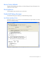
Restore Factory Defaults ................................................................................................................. 71
Reset Appliance ............................................................................................................................ 71
Enable LDAP Debug Messages ........................................................................................................ 71
Set Web Interface Ports .................................................................................................................. 71
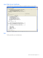
Input Web Server Certificate ........................................................................................................... 72
Exit .............................................................................................................................................. 72
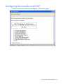
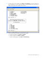
Configuring the console switch NIC ........................................................................................................... 73
Recovering a lost console switch serial management password ..................................................................... 76
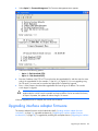
Upgrading the firmware .............................................................................................................. 78
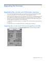
Upgrading the console switch firmware overview ........................................................................................ 78
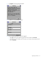
Upgrading the console switch firmware through the local OSD............................................................ 78
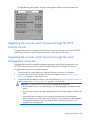
Upgrading the console switch firmware through the HP IP Console Viewer............................................ 80
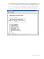
Upgrading the console switch firmware through the serial management connection ............................... 80
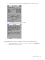
Upgrading interface adapter firmware ....................................................................................................... 82
Loading interface adapter firmware individually ................................................................................ 83
Upgrading the interface adapter firmware simultaneously ................................................................... 84
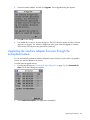
Upgrading the interface adapter firmware through the autoupdate feature ............................................ 85
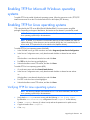
Enabling TFTP for Microsoft Windows operating systems .............................................................................. 86
Contents
4
Enabling TFTP for Linux operating systems .................................................................................................. 86
Verifying TFTP for Linux operating systems ........................................................................................ 86
Troubleshooting .......................................................................................................................... 88
Troubleshooting table .............................................................................................................................. 88
Connection length table ........................................................................................................................... 90
Frequently asked questions .......................................................................................................... 91
Are the expansion module ports hot-pluggable? .......................................................................................... 91
Are the interface adapters hot-pluggable? .................................................................................................. 91
Are the keyboard, monitor, and mouse connections on the console switch hot-pluggable? ................................ 91
Are the server connections on the console switch hot-pluggable? ................................................................... 91
Can the console switch be mounted in a round-hole rack? ............................................................................ 91
Can the console switch be side-mounted in a round-hole rack?...................................................................... 91
Has the customer verified the firmware version? .......................................................................................... 91
How do I access the Main dialog box? ...................................................................................................... 92
How do I cascade console switches? ......................................................................................................... 92
How do I change the keyboard language? ................................................................................................. 92
How do I know which port my cascaded console switch is connected to? ....................................................... 92
How do I locally connect a cascaded console switch?.................................................................................. 93
How do I look at my console switch firmware version? ................................................................................. 93
How do I look at my interface adapter firmware version? ............................................................................. 93
How do I turn the screen saver off?............................................................................................................ 93
How do I use the Run Diagnostics feature? ................................................................................................. 93
Is the console switch operational?.............................................................................................................. 93
What are the minimum and maximum cable lengths?................................................................................... 94
What kind of CAT5 cables are supported? ................................................................................................. 94
Technical support........................................................................................................................ 95
Before you contact HP.............................................................................................................................. 95
HP contact information ............................................................................................................................. 95
Regulatory compliance notices ..................................................................................................... 96
Regulatory compliance identification numbers ............................................................................................. 96
Federal Communications Commission notice............................................................................................... 96
FCC rating label............................................................................................................................ 96
Class A equipment......................................................................................................................... 96
Declaration of conformity for products marked with the FCC logo, United States only....................................... 96
Modifications.......................................................................................................................................... 97
Cables ................................................................................................................................................... 97
Canadian notice ..................................................................................................................................... 97
European Union regulatory notice ............................................................................................................. 97
Disposal of waste equipment by users in private households in the European Union ......................................... 98
Japanese notice ...................................................................................................................................... 98
Korean class A notice .............................................................................................................................. 99
Power cord statement for Japan................................................................................................................. 99
Acronyms and abbreviations...................................................................................................... 100
Index....................................................................................................................................... 102
Contents
5
Component identification
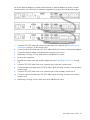
Console switch components
Item
Description
1
Power cord connector
2
Power switch
3
Fans
4
Activity indicator light
5
LAN connector (10/100/1000 gigabit)
6
Serial management connector
7
Mouse connector for local user
8
Keyboard connector for local user
9
Video connector for local user
10
USB ports
11
Server connection ports
Component identification 6
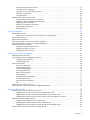
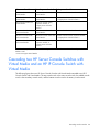
Interface adapter with Virtual Media components
Interface adapters that support Virtual Media have two LEDs on the front of the RJ-45 connector.
Item
Description
1
When lit, this LED indicates that the interface adapter has power from
the server.
2
When lit, this LED indicates that there is an active console session
with the interface adapter.
When flashing, this LED indicates that the interface adapter firmware
is being upgraded.
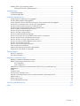
USB 2.0 interface adapter with Virtual Media
Item
Description
1
Video connector
Component identification 7
Item
Description
2
RJ-45 connector
3
USB connector
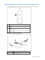
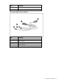
PS2 interface adapter with Virtual Media
Item
Description
1
Video connector
2
RJ-45 connector
3
USB connector (for Virtual Media only)
4
Mouse connector
5
Keyboard connector
Component identification 8
Installing the console switch
Installation overview
This product ships with rack-mounting brackets for easy integration into the rack. Before installing this
product and other components in the rack cabinet (if they are not already installed), stabilize the rack in a
permanent location. Begin installing the equipment at the bottom of the rack cabinet, and then work to the
top. Avoid uneven loading or overloading of the rack cabinets.
Rack-mount safety instructions
When rack-mounting a console switch, consider the following factors:
•
Elevated operating ambient temperature—If the equipment is installed in a closed or multi-unit rack
assembly, the operating ambient temperature of the rack environment might be greater than room
ambient temperature. Install the equipment in an environment compatible with the operating
temperature.
•
Reduced air flow—In the rack, the rate of air flow required for safe operation of the equipment must
not be compromised.
•
Mechanical loading—Avoid a potentially hazardous condition caused by uneven mechanical
loading by carefully mounting the equipment in the rack.
•
Circuit overloading—When connecting the equipment to the supply circuit, consider the effect that
overloading of the circuits might have on overcurrent protection and supply wiring. Consider the
equipment nameplate ratings when addressing this concern.
•
Reliable earthing—Maintain reliable earthing of rack-mounted equipment. Pay particular attention to
supply connections other than direct connections to the branch circuit, such as the use of power
strips.
Installation checklist
Before installation, refer to the following lists to be sure that all of the listed components were received.
Console switch kit contents
•
Console switch
•
Power cords
•
Rack mounting kit
•
Serial cable
•
Documentation kit
This kit might contain extra hardware for your convenience.
Installing the console switch
9
Required items not included
•
Interface adapters ("Installing the interface adapter" on page 21)
One interface adapter is needed for each server or device.
•
o
USB 2.0 with Virtual Media
o
PS2 with Virtual Media
o
USB (not Virtual Media capable)
o
PS2 (not Virtual Media capable)
o
Serial
o
HP BladeSystem CAT5 KVM (not Virtual Media capable)
UTP CAT5 cable (CAT6 and CAT7 can also be used)
Optional item
Expansion module (not Virtual Media capable)
Required tools
The following tools are required for some procedures:
•
Phillips screwdriver
•
Cage nut insertion tool (included with your original rack hardware kit)
Rack-mounting the console switch
NOTE: Before installing the console switch into the rack, connect the console switch to a
power source, using the power cords provided, and power on the unit. An activity indicator
light ("Console switch components" on page 6) is displayed after a few seconds. If the activity
indicator light does not display, be sure that the power is on, the power cord is connected,
and the power source is valid.
Several rack-mounting configurations include:
•
Side-mount
o
Type A—Square- and round-hole rails
o
Type B—Square-hole rails
NOTE: The console switch cannot be side-mounted into a rack with round-hole rails.
•
Standard-mount
•
Cantilever-mount
o
Type A—Round-hole rails
o
Type B—Square-hole rails
Installing the console switch
10
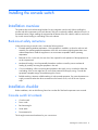
Performing a side-mount type A installation
1.
Remove the four screws, two on each side, from the console switch.
2.
Attach the side-mounting brackets to the console switch using the four screws that you removed.
3.
Slide the side-mounting bracket tabs into the U locations on each side of the rack.
Installing the console switch
11
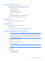
4.
Secure the console switch to the rails using four self-tapping screws, two on each side.
Performing a side-mount type B installation
1.
Remove the four screws, two on each side, from the console switch.
2.
Attach the side-mounting brackets to the console switch using the four screws that you removed.
Installing the console switch
12
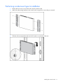
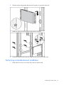
3.
Slide the side-mounting bracket tabs into the U locations on each side of the rack.
4.
Install four cage nuts into the side-mounting bracket U locations.
5.
Secure the console switch to the rails, using four M-6 screws, two on each side.
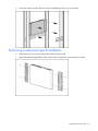
Performing a standard-mount installation
1.
Remove the four screws, two on each side, from the console switch.
Installing the console switch
13
2.
Attach the 1U brackets to the console switch using the four screws that you removed.
3.
Install a cage nut behind each rear rail, if the cage nuts have not already been installed.
Installing the console switch
14
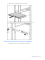
4.
Slide the console switch behind the rear of the 1U product.
5.
Secure the console switch to the rails using two M-6 screws, one on each side.
Performing a cantilever-mount type A installation
1.
Remove the four screws, two on each side, from the console switch.
Installing the console switch
15
2.
Attach the 1U brackets to the console switch using the four screws that you removed.
3.
Install up to six clip nuts.
Installing the console switch
16
4.
Secure the console switch to the rails, using the appropriate number of T-25 Torx screws.
Performing a cantilever-mount type B installation
1.
Remove the four screws, two on each side, from the console switch.
2.
Attach the 1U brackets to the console switch using the four screws that you removed.
Installing the console switch
17
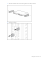
3.
Install up to six cage nuts.
4.
Secure the console switch to the rails using the appropriate number of M-6 screws.
Connecting the console switch
1.
Connect the local keyboard, video, and mouse to the console switch.
Installing the console switch
18
WARNING: To reduce the risk of electric shock or damage to the equipment:
• Do not disable the power cord grounding plug. The grounding plug is an important safety
feature.
• Plug the power cord into a grounded (earthed) electrical outlet that is easily accessible at all
times.
• Unplug the power cord from the power supply to disconnect power to the equipment.
• Do not route the power cord where it can be walked on or pinched by items placed against
it. Pay particular attention to the plug, electrical outlet, and the point where the cord
extends from the storage system.
2.
Plug the console switch power cord into a power source.
3.
Power on the console switch. The activity indicator light ("Console switch components" on page 6)
powers on.
NOTE: UTP CAT5 cables are used throughout the examples in this guide. However, UTP CAT6
and UTP CAT7 cables may also be used.
4.
Connect a UTP CAT5 cable to the LAN connector on the console switch.
5.
Connect the other end of that same UTP CAT5 cable to an Ethernet switch.
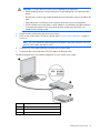
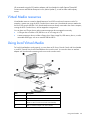
The following figure shows one possible configuration for your console switch system.
Item
Description
1
Local console
2
Console switch
3
Ethernet switch
Installing the console switch
19
HP IP Console Viewer overview
You must install the HP IP Console Viewer software if you want to use the software to configure the
console switch. The HP IP Console Viewer enables you to view and control a server attached to the
console switch system, configure and maintain the system, and prevent unauthorized access to the
console switch through IP connections. For more information, see the HP IP Console Viewer User Guide
included on the CD provided with this product.
NOTE: The analog port does not require the HP IP Console Viewer software for operation. The
analog port uses the OSD. For more information, refer to "Local port operation (on page 28)."
The console switch system uses Ethernet networking infrastructures and the TCP/IP protocol to transmit
keyboard, video, and mouse information between operators and connected computers. Although 10BaseT Ethernet can be used, a dedicated, switched 100Base-T network provides improved performance.
Installing the console switch
20
Installing the interface adapter
Interface adapter overview
An interface adapter is required for the console switch system to function properly. However, an interface
adapter is not included in the console switch kit. The interface adapter is connected to a console switch
using a CAT5 cable.
NOTE: UTP CAT5 cables are used throughout the examples in this guide. However, UTP CAT6
and UTP CAT7 cables may also be used.
For Virtual Media to function properly, you must have the following:
•
•
Interface adapters with Virtual Media (one interface adapter is needed for each server or device)
o
HP USB 2.0 Interface Adapter with Virtual Media
o
HP PS2 Interface Adapter with Virtual Media
Console switches with Virtual Media
o
HP IP Console Switch with Virtual Media
o
HP Server Console Switch with Virtual Media
You cannot use interface adapters with Virtual Media to connect to console switches that do not support
Virtual Media.
Connecting the interface adapter
1.
Connect a UTP CAT5 cable to the server connection port ("Console switch components" on page 6)
on the console switch.
2.
Connect the other end of that same UTP CAT5 cable to the RJ-45 connector on the interface adapter.
3.
Connect the interface adapter to the appropriate connectors on the server.
4.
Repeat the preceding steps to connect any other servers to this system.
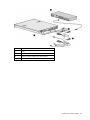
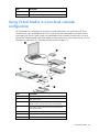
The following figure shows one possible configuration for the console switch system with an interface
adapter.
Installing the interface adapter
21
Item
Description
1
Server
2
Console switch
3
USB 2.0 interface adapter with Virtual Media
4
PS2 interface adapter with Virtual Media
Installing the interface adapter
22
Cascading console switches
Cascading console switches overview
Review the following information before you cascade console switches with this product. This product
supports three levels of cascading.
NOTE: The console switch does not support Compaq KVM PCI Cards or HP legacy console
switches.
You can cascade multiple console switches to enable one or two users to connect up to 4096 servers.
For Virtual Media to be supported in a cascaded console switch system, you must use the following
console switches:
•
HP 2 x 1 x 16 IP Console Switch with Virtual Media [PN: AF601A]
•
HP 4 x 1 x 16 IP Console Switch with Virtual Media [PN: AF602A]
•
HP 2 x 16 Server Console Switch with Virtual Media [PN: AF600A]
When cascading console switches with Virtual Media, be sure the following requirements are met:
•
HP Server Console Switches with Virtual Media are cascaded below HP IP Console Switches with
Virtual Media.
•
Interface adapters are not used to cascade console switches. If interface adapters are used to
cascade console switches, you will not have a seamlessly integrated OSD, and you lose Virtual
Media support.
•
Cascaded console switches have the most current firmware. To upgrade console switch firmware,
see "Upgrading the firmware (on page 78)."
Cascading console switches matrix
As shown in the following table, for Virtual Media to work properly in a two-level cascade configuration,
you must have an HP Server Console Switch with Virtual Media or an HP IP Console Switch with Virtual
Media as the main console switch and an HP Server Console Switch with Virtual Media as the secondary
console switch. For Virtual Media to work properly in a three-level cascade configuration, you must have
an HP Server Console Switch with Virtual Media or an HP IP Console Switch with Virtual Media as the
main console switch and an HP Server Console Switch with Virtual Media as the secondary and tertiary
console switches. For both configurations to work properly, you must have an interface adapter with
Virtual Media connecting each server to the console switch. For more information, see "Using Virtual
Media (on page 58)."
HP Server Console Switches, expansion modules, and Compaq Server Console Switches are not Virtual
Media capable. When cascading an HP Server Console Switch, expansion module, and Compaq Server
Console Switch, you cannot tier any console switches below them. See the following table.
Cascading console switches
23
Main console switch
Secondary console switch
Tertiary console switch
HP IP Console Switch with
Virtual Media*
HP Server Console Switch with HP Server Console Switch with Virtual Media*
Virtual Media*
HP IP Console Switch with
Virtual Media*
HP Server Console Switch with HP Server Console Switch, expansion module,
Virtual Media*
or Compaq Server Console Switch**
HP IP Console Switch with
Virtual Media*
HP Server Console Switch,
expansion module, or
Compaq Server Console
Switch**
HP Server Console Switch
with Virtual Media*
HP Server Console Switch with HP Server Console Switch with Virtual Media*
Virtual Media*
HP Server Console Switch
with Virtual Media*
HP Server Console Switch with HP Server Console Switch, expansion module,
Virtual Media*
or Compaq Server Console Switch**
HP Server Console Switch
with Virtual Media*
HP Server Console Switch,
expansion module, or
Compaq Server Console
Switch**
—
—
*Virtual Media capable if a USB 2.0 interface adapter with Virtual Media or a PS2 interface adapter with Virtual
Media is used.
**Does not support Virtual Media.
Cascading two HP Server Console Switches with
Virtual Media and an HP IP Console Switch with
Virtual Media
The following figure shows two HP Server Console Switches with Virtual Media cascaded to an HP IP
Console Switch with Virtual Media. The top console switch is the main console switch, the middle console
switch is the secondary console switch, and the bottom console switch is the tertiary console switch.
Cascading console switches
24
Do not use interface adapters to cascade console switches. If interface adapters are used to cascade
console switches, you will not have a seamlessly integrated OSD, and you lose Virtual Media support.
1.
Connect a UTP CAT5 cable and connect one end to the server connection port ("Console switch
components" on page 6) on the console switch.
2.
Connect the other end of that same UTP CAT5 cable to the RJ-45 connector on the interface adapter.
3.
Connect the interface adapter to the appropriate connectors on the server.
4.
Repeat steps 1 through 3 for any other servers to be added to this system.
5.
Power up the components.
6.
Upgrade the console switch and interface adapter firmware ("Upgrading the firmware" on page
78).
7.
Connect a UTP CAT5 cable to the server connection port on the main console switch.
8.
Connect the other end of that same UTP CAT5 cable to the RJ-45 tiering connector on the secondary
console switch.
9.
Connect a UTP CAT5 cable to the server connection port on the secondary console switch.
10.
Connect the other end of that same UTP CAT5 cable to the RJ-45 tiering connector on the tertiary
console switch.
11.
Repeat steps 1 through 3 for any other server to be added to this system.
Cascading console switches
25
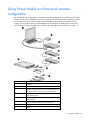
Example of an HP Server Console Switch with Virtual Media
and an HP IP Console Switch with Virtual Media cascade
configuration
Item
Description
1
Servers
Cascading console switches
26
Item
Description
2
Main console switch (HP IP Console Switch with Virtual
Media)
3
Interface adapters (USB 2.0 interface adapter with
Virtual Media or PS2 interface adapter with Virtual
Media)
4
UTP CAT5 cable
5
UTP CAT5 cable
6
Local console KVM cables
7
Local console
8
Secondary console switch (HP Server Console Switch
with Virtual Media)
9
Tertiary console switch (HP Server Console Switch with
Virtual Media)
10
Servers
11
Interface adapters (USB 2.0 interface adapter with
Virtual Media or PS2 interface adapter with Virtual
Media)
12
UTP CAT5 cable
Cascading console switches
27
Local port operation
Local port operation overview
The console switch system has one local port on the rear panel ("Console switch components" on page 6)
that enables you to connect a keyboard, monitor, and mouse to the console switch for direct access.
Use the Main dialog box ("Accessing the Main dialog box" on page 28) to view, configure, and control
servers in the console switch system. You can also clear offline interface adapters by clicking the Clear
button.
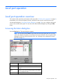
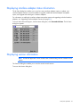
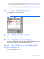
Accessing the Main dialog box
Press the Print Scrn key. The Main dialog box appears.
NOTE: You can also press the Ctrl key twice within one second to launch the OSD. You can
use this key sequence any place you see the Print Scrn key mentioned in this user guide. Other
keystrokes can also be used to launch the OSD. See "Selecting a key combination to launch
the OSD (on page 33)."
Button
Description
Clear
Enables you to clear all offline interface adapters.
Disconnect
Enables you to disconnect the local console KVM
session.
Setup
Enables you to access the Setup dialog box and enables
you to configure the OSD.
Commands
Enables you to access the Commands dialog box.
Local port operation 28
Button
Description
VMedia
Enables you to set Virtual Media options and make
Virtual Media connections. This button is available only
when a KVM session is established to an interface
adapter with Virtual Media capability.
Viewing servers by name, EID, or port
You can view servers by name (default) by the unique EID embedded in each interface adapter or by the
port.
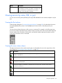
Viewing the Port column
When the Main dialog box ("Accessing the Main dialog box" on page 28) is first launched, the servers
are listed alphabetically by name. Press the Port button to list the servers numerically by their port
numbers.
The Port column indicates the port to which a server is connected. For example, in the following screen
shot, the first number represents the port number of the first console switch, the second number represents
the port number of the secondary console switch, and the third number represents the tertiary console
switch port to which the server is connected.
Viewing the server status column
The status of the servers in the console switch system is indicated by the icons in the right column of the
Main dialog box ("Accessing the Main dialog box" on page 28).
Icon
Description
The interface adapter is connected directly, cascaded through a console switch or an expansion
module, or powered on.
The interface adapter is not connected, or the server is powered off.
The interface adapter is cascaded to a Compaq Server Console Switch, and the console switch is not
connected or is powered off.
The interface adapter is cascaded to a Compaq Server Console Switch, and the console switch is
connected or powered on.
The interface adapter is being upgraded.
This symbol identifies the port to which the local console is connected.
Local port operation 29
Icon
Description
This symbol identifies which port you are actively connected to and viewing.
This symbol identifies an unavailable server.
This symbol identifies a Virtual Media connection is established to the server that is connected to the
indicated user channel.
Soft switching
Soft switching is the ability to switch servers using a hotkey sequence. You can soft switch to a server by
pressing the Print Scrn key, entering the first few characters of the server's name or port number, and
pressing the Enter key.
Soft switching to a server
If the display order of your server list is by port, press the Print Scrn key, select the Port, and press the
Enter key.
If the display order of your server list is by name, press the Print Scrn key, select the Name, and press the
Enter key.
Soft switching to a previous server
Press the Print Scrn key, then press the Backspace key. This key combination toggles between the previous
and current connection.
Disconnecting from a server
Press the Print Scrn key and press the Alt+0 keys, or click Disconnect. If there is an associated locked
Virtual Media session, it is disconnected.
Disconnecting from a server leaves the console switch in a free state. The status flag ("Controlling the
status flag" on page 33) on the OSD appears as Free.
Using basic OSD navigation keys
The following table describes how to navigate the OSD using the keyboard and mouse.
Keystroke
Description
Print Scrn
Opens the Main dialog box. Press the Print Scrn key twice to send the Print
Scrn keystroke to the currently selected device.
Ctrl+Ctrl, Shift+Shift, or
Alt+Alt
Opens the Main dialog box (if assigned in the Menu dialog box).
F1
Opens the Help screen for the current dialog box.
Local port operation 30
Keystroke
Description
Esc
Closes the current dialog box without saving changes and returns to the
previous dialog box. In the Main dialog box, it closes the OSD and returns to
the selected server. In a message box, it closes the message box and returns to
the current dialog box.
Alt+Hotkey
Opens dialog boxes, selects options, and executes actions when used in
combination with the other keys.
Alt+X
Closes the current dialog box and returns to the previous dialog box.
Alt+O
Selects the OK button and returns to the previous dialog box.
Enter
Selects the highlighted server and closes the Main dialog box.
Single-click, Enter
Selects the text, in a text box, for editing and enables the left and right arrow
keys to move the cursor. Press the Enter key again to quit Edit mode.
Print Scrn, Backspace
Toggles back to the previous server console selection
Print Scrn, Alt+0
Disengages the user immediately from a server and leaves no server selected.
The status Flag appears as Free. (This command applies only to the 0 key on
the keyboard, not to the 0 key on the keypad.)
Print Scrn, Pause
Activates the Screen Saver mode immediately and prevents access to that
particular console if it is password protected.
Up or Down arrows
Moves the cursor from line to line.
Right or Left arrows
Moves the cursor between columns. When you are editing a text box, these
keys move the cursor within the column.
Page Up or Page Down
Pages up and down through the Name and Port lists.
Home or End
Moves the cursor to the top or bottom of a list.
Backspace
Erases characters in a text box.
Delete
Deletes the current selection in the Scan dialog box or deletes the characters in
a text box.
Shift, Delete
Deletes the current selection and all lines below it when you are editing a
scan list.
Numbers
Adds numbers from the keyboard or keypad.
Caps Lock
Disables the selected user. (Use the Shift key to change case.)
Managing routine tasks for servers
You can configure the console switch and manage routine tasks for your servers from the Setup dialog
box within the OSD. To identify servers by unique names, click Names when initially setting up your
console switch.
Local port operation 31
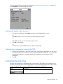
To access the Setup dialog box, click Main>Setup. The Setup dialog box appears.
Button
Description
Menu
Changes the server listing to display numerically by port, numerically by EID number, or
alphabetically by name.
Changes the key combination to launch the OSD.
Flag
Changes the type of display, timing, color, and location of the status flag.
Devices
Changes the device type from a server to a console switch and identifies the number of ports
on the console switch.
Keyboard
Changes the keyboard country code reported by the interface adapter.
Network
Changes the network speed and configuration. You can specify the IP address, netmask, and
gateway for the system.
Security
Sets password to restrict KVM access. A valid password must be alphanumeric and contain a
minimum of five characters and a maximum of 15 characters. Permitted characters are casesensitive and can consist of A–Z, 0–9, spaces, and hyphens.
Enables the Screen Saver mode.
Language
Changes the OSD language display.
Names
Enables you to name interface adapters.
Scan
Sets up custom scan patterns for up to 100 servers.
Preempt
Enables a user to preempt another user, remote or local.
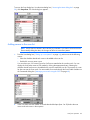
Changing the display behavior
From the Menu dialog box, you can change the display order of servers and the key combination used to
launch the OSD. The display order setting alters how servers appear in several places, including the
Main, Devices, and Scan dialog boxes.
Local port operation 32
To access the Menu dialog, from the Main dialog box ("Accessing the Main dialog box" on page 28),
click Setup>Menu. The Menu dialog box appears.
Selecting the display order of servers
1.
From the Menu dialog box, select Name to display servers alphabetically by name.
-orSelect EID to display servers numerically by interface adapter ID number.
-orSelect Port to display servers numerically by port number.
2.
Click OK to save settings.
-orClick X to exit, or press the Esc key to exit without saving settings.
Selecting a key combination to launch the OSD
1.
From the Menu dialog box, in the Invoke OSD section, select the key combinations you want to use
to launch the OSD. You can select one or all of the listed keyboard combinations. If you select only
one keyboard combination, you cannot deselect the combination until you select a second
combination.
2.
Click OK.
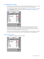
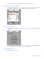
Controlling the status flag
The status flag is displayed on the desktop and shows the name or EID number of the selected server or
the status of a particular port. Use the Flag dialog box to change the flag display by server name or EID
number, change the flag color, opacity, display time, or location on the desktop.
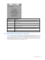
Flag
Description
Flag type by name
Local port operation 33
Flag
Description
Flag type by EID number
Flag indicating that the user has been disconnected from all systems
Control that is used to set flag position
Changing the status flag
1.
From the Main dialog box ("Accessing the Main dialog box" on page 28), click Setup>Flag. The
Flag Setup dialog box appears.
2.
Select Name or EID to determine what information appears on the flag in the Flag Type area.
3.
Select Displayed (default) to show the flag constantly, and select Timed to display the flag for only
five seconds after soft switching.
4.
Select a flag color in the Display Color area.
5.
Select Opaque for a solid-color flag, or select Transparent to see the desktop through the flag in the
Display Mode area.
6.
Position the status flag on the desktop:
a. Click Set Position to access the Set Position flag. The Set Position flag appears.
b. Click and hold the title bar, and then drag the flag to the desired location.
c.
7.
Right-click to return to the Flag dialog box.
Click OK to save settings, or press the Esc key to exit without saving settings. Changes made to the
flag are not saved until you click OK.
Local port operation 34
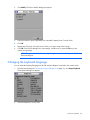
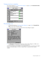
Assigning device types
The console switch automatically discovers cascaded console switches attached to your unit, but you must
specify the number of ports on the cascade console switches through the Devices dialog box.
To access the Devices dialog box, from the Main dialog box ("Accessing the Main dialog box" on page
28), click Setup>Devices. The Devices dialog box appears. The Modify button is available only if a
configurable console switch is selected.
When the console switch discovers a cascaded console switch, the port numbers shown in the Port
column change automatically to accommodate each server shown under that console switch. For
example, if the console switch is connected to port 02, the switch port is listed as 02, and each server
shown under it is numbered sequentially 02-01, 02-02, and so on.
However, when the console switch discovers a cascaded Compaq Server Console Switch, you must select
the number of ports on the Compaq Server Console Switch through the Device Modify dialog box.
Modifying device types
1.
From the Devices dialog box, select the Port number.
Local port operation 35
2.
Click Modify. The Device Modify dialog box appears.
3.
Select the number of ports supported by the cascaded Compaq Server Console Switch.
4.
Click OK.
5.
Repeat steps 2 through 4 for each port to which you want to assign a device type.
6.
Click OK in the Devices dialog box to save settings, click X to exit, or press the Esc key to exit
without saving settings.
NOTE: Changes made in the Device Modify dialog box are not saved until you click OK in the
Devices dialog box.
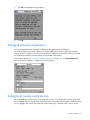
Changing the keyboard language
You can select the keyboard language for all USB interface adapters connected to the console switch.
1.
From the Main dialog box ("Accessing the Main dialog box" on page 28), click Setup>Keyboard.
The Keyboard dialog box appears.
2.
Select the Keyboard Country Code.
Local port operation 36
3.
Click OK. A Keyboard Warning appears.
4.
Click OK.
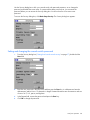
Changing network configurations
You can change the network speed and configuration through the Network dialog box.
The console switch system uses IP addresses to uniquely identify the console switches and computers
running the HP IP Console Viewer. HP recommends that IP addresses be reserved for each unit and that
they remain static while the console switches are connected to the network.
From the Main dialog box ("Accessing the Main dialog box" on page 28), click Setup>Network. The
Network dialog box appears. Configure your network settings.
Setting local console switch security
The OSD enables you to set security on the local port consoles. You can establish a Screen Saver mode
that is engaged after the console switch remains unused for a user-definable time delay. When the screen
saver is engaged, the console switch remains locked until any key is pressed or the mouse is moved.
Local port operation 37
Use the Security dialog box to lock your console switch with password protection, set or change the
password, and enable the screen saver. If a password has been previously set, you must enter the
password before you can access the Security dialog box. You do not have to set a screen saver
password.
To access the Security dialog box, click Main>Setup>Security. The Security dialog box appears.
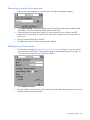
Setting and changing the console switch password
1.
From the Security dialog box ("Setting local console switch security" on page 37), double-click the
New field.
2.
Enter the new password in the New field, and then press the Enter key. A valid password must be
alphanumeric and be five to 15 characters in length. Permitted characters are case-sensitive and can
consist of A–Z, 0–9, spaces, and hyphens.
3.
In the Repeat field, re-enter the password and press the Enter key.
4.
Click OK to change the password.
Local port operation 38
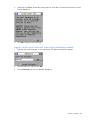
Recovering a console switch password
1.
Press any key on the keyboard, or move the mouse. The Authorize dialog box appears.
2.
Click Forgot Password. A dialog box appears with an HP technical support phone number (1-800474-6836), a 16-bit key, and the EID number of the console switch.
3.
Call the HP technical support phone number. Give the service person your 16-bit key and EID
number of the console switch. A one-time unlock code, which is specific to your console switch, is
given to you.
4.
Enter the one-time unlock code in the field.
5.
Click OK. Your previous console switch password is deleted.
Enabling Screen Saver mode
1.
From the Security dialog box ("Setting local console switch security" on page 37), set your console
switch password as described in "Setting and changing the console switch password (on page 38)"
if you want to password protect your Screen Saver mode.
2.
Select Enable Screen Saver.
3.
Enter the number of minutes (from 1 to 99) in the Inactivity Time field to delay activation of password
protection and the screen saver feature.
Local port operation 39
4.
(Optional) Click Test to activate the screen saver test, which lasts 10 seconds and returns you to the
Security dialog box.
5.
Click OK to start the screen saver test.
Logging in to the console switch (after Screen Saver mode has been enabled)
1.
Press any key on the keyboard, or move the mouse. The Authorize dialog box appears.
2.
Enter the password, and then click OK.
3.
Press the Print Scrn key to access the Main dialog box.
Local port operation 40
Disabling the Screen Saver mode
1.
From the Security dialog box ("Setting local console switch security" on page 37), clear the Enable
Screen Saver option.
2.
Click OK to save settings.
To immediately deactivate the screen saver, press the Print Scrn key, and then press the Pause key. This
command works only when you are connected to a server.
Removing screen saver password protection
1.
From the Main dialog box ("Accessing the Main dialog box" on page 28), click Setup>Security. The
Authorize dialog box appears.
Local port operation 41
2.
Enter the console switch password, and then click OK. The Security dialog box appears.
3.
Double-click the New field, leave the New field blank, and press the Enter key.
4.
Double-click the Repeat field, leave the Repeat field blank, and press the Enter key.
5.
Click OK if you want to remove the console switch password.
Exiting Screen Saver mode
To exit the Screen Saver mode, press any key or move the mouse. The Main dialog box ("Accessing the
Main dialog box" on page 28) appears and the previously selected server is reconnected.
Local port operation 42
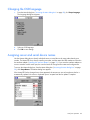
Changing the OSD language
1.
From the Main dialog box ("Accessing the Main dialog box" on page 28), click Setup>Language.
The Language dialog box appears.
2.
Select an OSD language.
3.
Click OK to save settings.
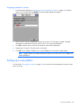
Assigning server and serial device names
Use the Names dialog box to identify individual servers or serial devices by name rather than by port
number. The Name/EID list is always sorted by port order, and the names and EID numbers are stored in
the interface adapter ("Installing the interface adapter" on page 21). If you move the interface adapter or
server to another console switch port, the console switch still recognizes the names and configurations.
To access the Names dialog box, from the Main dialog box ("Accessing the Main dialog box" on page
28), click Setup>Names. The Names dialog box appears.
If the Name/EID list has changed since it last appeared, the mouse turns into an hourglass as the list is
automatically updated. No mouse or keyboard input is accepted until the list update is complete.
Local port operation 43
Assigning names to servers
1.
From the Names dialog box ("Assigning server and serial device names" on page 43), select the
name or port number and click Modify. The Name Modify dialog box appears.
2.
Enter a name in the New Name field. Names can be one to 15 characters in length. Permitted
characters are case-sensitive and can consist of A–Z, 0–9, spaces, and hyphens.
3.
Click OK to transfer the new name to the names list in the Names dialog box.
4.
Repeat steps 1 through 3 for each server in the system.
5.
Click OK to save settings, click X to exit, or press the Esc key to exit without saving settings.
NOTE: Changes made in the Name Modify dialog box are not saved until you click OK in the
Names dialog box.
Setting up a scan pattern
In Scan mode ("Activating Scan mode" on page 46), the console switch automatically scans port to port
(server to server).
Local port operation 44
To access the Scan dialog box, from the Main dialog box ("Accessing the Main dialog box" on page
28), click Setup>Scan. The Scan dialog box appears.
Adding servers to the scan list
NOTE: Servers will be scanned in the order they are selected. If you remove a server from the
Device Modify dialog box later, the change can affect a custom scan pattern.
1.
From the Scan dialog box ("Setting up a scan pattern" on page 44), perform one of the following
actions:
o
Select the checkbox beside each server to be added to the scan list.
o
Double-click a server name or port.
You can select up to 100 servers from a list of all servers attached to the console switch. You can
display the list by either name or EID number by clicking the appropriate button. Selecting the
checkbox beside each server to be added to the scan list creates the scan list. The creation of a scan
list does not start the Scan mode. You must enable Scan mode through the Scan Enable checkbox on
the Commands dialog box ("Managing server tasks using the OSD" on page 48).
2.
In the Time field, enter the number of seconds that should elapse (from 3 to 99) before the scan
moves to the next server in the sequence.
Local port operation 45
3.
Click OK to save settings, or click Clear to remove all servers from the scan list.
Removing servers from the scan list
1.
From the Scan dialog box ("Setting up a scan pattern" on page 44), click the server to be removed,
double-click a server name or port, or click Clear to remove all servers from the scan list.
2.
Click OK to save settings.
Activating Scan mode
1.
From the Commands dialog box ("Managing server tasks using the OSD" on page 48), select Scan
Enable.
2.
Click X to close the Commands dialog box. The scan begins as soon as you click the Scan button in
the Setup dialog box ("Managing routine tasks for servers" on page 31).
Deactivating Scan mode
If the OSD is open, select a server.
-or-
Local port operation 46
If the OSD is not open, move the mouse or press any key on the keyboard. Scanning stops at the currently
selected server.
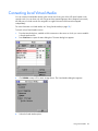
-orFrom the Commands dialog box, deselect Scan Enable. Any active connections on the local port are
disconnected.
Using preemption
Preemption provides a means for users with sufficient access level to take control of a server from another
(remote or local) user who has a lesser or equal access level. Depending on the access level of the user
issuing the preemption request and that of the user being preempted, the preemption request can be
rejected. The Override Admin account is treated as a Console Switch Administrator in the following table.
User level
Preempted by
Can the preemption
be rejected?
Local user
Console Switch
Administrator (Override
Admin)
Yes
Console Switch
Administrator
(Override Admin)
Local user
Yes
Console Switch
Administrator
(Override Admin)
Console Switch
Administrator (Override
Admin)
Yes
Remote user
Local user
No
Remote user
Console Switch
Administrator (Override
Admin)
No
Assigning a preempt timeout
1.
From the Main dialog box ("Accessing the Main dialog box" on page 28), click Setup>Preempt. The
Preempt dialog box appears.
2.
Enter a value in the Timeout Seconds field, and click OK.
Local port operation 47
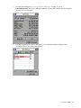
When you attempt to preempt another user or Admin, a Message appears on your screen, and a
Preempt Warning appears on the screen of the user or Admin.
These messages appear for the time assigned in the Timeout Seconds field set through either the
local OSD or the HP IP Console Viewer. If the user you are preempting does not respond within the
selected time, the user is disconnected and the preemption is granted.
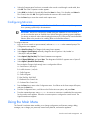
Managing server tasks using the OSD
You can manage the console switch system from the Commands dialog box with the OSD.
Managing the console switch system includes engaging Scan mode, managing user connections, running
diagnostics, and updating your firmware.
To access the Commands dialog box, click Main>Commands. The Commands dialog box appears.
Local port operation 48
Checkbox or button
Description
Scan Enable
Begins scanning your servers. Sets up a list for scanning in the Setup dialog box.
User Status
Displays users and Virtual Media sessions and enables you to disconnect users and
Virtual Media sessions.
IA Status
Upgrades multiple interface adapters simultaneously.
Display Versions
Displays version information and enables you to upgrade console switch and
interface adapter firmware.
Display Config
Displays settings.
Run Diagnostics
Validates the integrity of your system, including firmware CRC and interface
adapters.
Device Reset
Reestablishes the operation of the keyboard and mouse.
Viewing and disconnecting user connections
You can view and disconnect remote network users through the User Status dialog box ("Viewing current
user connections" on page 50). The user name (U) is always displayed. However, either the server name
or interface adapter ID number to which the user is connected can also be displayed. The User Status
dialog box displays only the number of users the system supports. If no users are currently connected to a
channel, the fields are blank and the server indicates it is free.
Local port operation 49
Viewing current user connections
From the Main dialog box ("Accessing the Main dialog box" on page 28), click Commands>User Status.
The User Status dialog box appears.
Disconnecting a user
1.
From the Main dialog box ("Accessing the Main dialog box" on page 28), click Commands>User
Status. The User Status dialog box appears.
2.
Click the letter of the user to be disconnected. The Disconnect dialog box appears.
3.
Click Disconnect to disconnect the user and return to the User Status dialog box, click X to exit, or
press the Esc key to exit the dialog box without disconnecting a user.
If the User Status dialog box has changed since it last appeared, the mouse cursor becomes an hourglass
as the list automatically updates. No mouse or keyboard input is accepted until the list update is
complete.
Local port operation 50
Displaying interface adapter status information
The IA Status dialog box enables you to view how many interface adapters require an update, view
interface adapter firmware versions available for upgrade, enable the interface adapter autoupdate
option, and upgrade individual types of interface adapters.
For information on enabling the interface adapter autoupdate option and upgrading individual interface
adapters, see "Upgrading interface adapter firmware (on page 82)."
To access the IA Status dialog box, from the Main dialog box, click Commands>IA Status. The IA Status
dialog box appears.
Displaying version information
NOTE: Provide the application version number when communicating with HP customer service
centers.
The Versions dialog box enables you to view the console switch versions.
To access the Version dialog box:
Local port operation 51
1.
From the Main dialog box ("Accessing the Main dialog box" on page 28), click
Commands>Versions. The Version dialog box appears. The top half of the box lists the subsystem
versions in the console switch.
2.
Click IA to access the IA Select dialog box to view individual interface adapter version information.
The IA Select dialog box appears.
Local port operation 52
3.
To view the selected interface adapter, click Version. The IA Version dialog box appears. The USB
2.0 Enable and USB 2.0 Disable buttons are only available on interface adapters with Virtual
Media.
4.
Click X to exit.
Decommissioning an interface adapter
You can reset individual interface adapters to factory defaults by using the following procedure:
1.
From the Main dialog box ("Accessing the Main dialog box" on page 28), click Commands>IA
Select. The IA Select dialog box appears.
2.
Select the individual interface adapter you want to decommission.
3.
Click Decommission. The associated server names, number of cascade ports, country code and
keyboard and mouse settings are set back to the factory defaults.
Displaying configuration information
The Config dialog box enables you to view the console switch configurations.
Local port operation 53
To access the Config dialog box, from the Main dialog box ("Accessing the Main dialog box" on page
28), click Commands>Config. The Config dialog box appears.
Running system diagnostics
You can validate the firmware CRCs and interface adapter status for the console switch through the Run
Diagnostics command.
To access the Diagnostics dialog box, click Commands>Run Diagnostics.
Test
Description
Firmware CRCs
Validates the current firmware images stored in the system FLASH by comparing a
CRC value on each image and comparing those results to the expected values.
Remote User Video
(digital only)
Verifies that all the video channel subsystems are accessible, functional, and
performing basic register level tests.
Local port operation 54
Test
Description
LAN Connection
(digital only)
Verifies the LAN connection is accessible and functional by verifying the link
controller is responsive and monitoring the network traffic.
•
If the link controller is responsive, the test-passes indictor appears.
•
If the link controller is non-responsive, the test-failed indictor appears.
•
If the link controller is functional but no network traffic has been displayed.
The LAN icon is green for up to one minute after the network cable has been
disconnected.
On-line IAs
Indicates the total number of currently connected and powered interface adapters.
Offline IAs
Indicates the number of interface adapters that have been connected successfully in
the past and are powered down.
Suspect IAs
Indicates the number of interface adapters that have been detected, but are either
unavailable for connection or have dropped packets during the ping tests.
Activating Run Diagnostics
1.
From the Main dialog box ("Accessing the Main dialog box" on page 28), click Commands>Run
Diagnostics. A warning message appears, indicating that all users will be disconnected.
2.
Perform one of the following actions:
o
Click OK to begin. All users are disconnected, and the Diagnostics dialog box appears.
o
Click X or press the Esc key to exit the dialog box without running a diagnostic test.
Local port operation 55
When each test is finished, a pass or fail symbol appears. A passed test is indicated with a green
circle, and a failed test is indicated by a red X. The test is complete when the last test symbol
appears.
3.
(Optional) If you have any offline interface adapters, click Clear to remove them from the list.
4.
(Optional) If you have any suspect interface adapters, click Display. The Suspect IAs dialog box
appears.
Resetting devices
If your local keyboard and mouse lock up, you can reestablish operation of these peripherals by issuing a
device reset. The device reset function resets the local keyboard and mouse for the local console.
Local port operation 56
1.
From the Main dialog box ("Accessing the Main dialog box" on page 28), click Commands. The
Commands dialog box appears.
2.
Click Device Reset. A warning appears, and the device is reset.
Local port operation 57
Using Virtual Media
Virtual Media overview
In this section on Virtual Media, the remote console for HP Server Console Switches with Virtual Media is
only available if the console switch is tiered underneath an HP IP Console Switch with Virtual Media.
The console switch enables you to connect shared media to a server using a USB connection. This
capability enables you to manage systems more efficiently by performing operating system installation,
operating system recovery, program installation, file transfers, and BIOS updates from the local or remote
console.
You can connect Virtual Media directly to the console switch using one of the USB ports located on the
rear of the console switch. In addition, you can connect Virtual Media from any remote workstation that is
running the HP IP Console Viewer and is connected to a server using an HP IP Console Switch with Virtual
Media. All USB ports of a local console are assigned to a single Virtual Media session and cannot be
mapped independently to different servers.
To open a Virtual Media session with a server, you must first connect the server to the console switch
using an interface adapter with Virtual Media and establish a local console session.
Using a console switch with Virtual Media, you can map a removable mass storage device or a CD/DVD
type device on the console as a virtual drive on a target server. You can also add and map an .iso or
floppy image file on the local client as a virtual drive on the target server if you are using the HP IP
Console Viewer.
Limitations of using USB 2.0 composite devices with Virtual
Media
The default functionality for Virtual Media for a USB 2.0 interface adapter with Virtual Media capability is
the composite high-speed USB 2.0 capability of the USB protocol. The BIOS and particular operating
systems and installation programs of various target servers do not support composite USB 2.0 devices. If
your target server BIOS or operating system does not support such devices, then you must perform one of
the following actions:
•
Purchase a PS2 interface adapter with Virtual Media and map a single Virtual Media device, which
operates in standard USB 2.0 mode.
•
Disable the USB 2.0 function of the USB 2.0 interface adapter with Virtual Media from the console
switch local OSD, enabling the interface adapter to operate in USB 1.1 mode. For more information
on this option, see "Disabling the USB 2.0 function (on page 63)."
AMD Opteron™-based HP ProLiant servers and Red Hat Enterprise Linux 4 (before Update 5) do not
currently support composite USB 2.0 devices. However, the target server BIOS for Intel®-based HP
ProLiant G4 and later servers support composite USB 2.0 devices. If the server BIOS supports USB 2.0
composite devices, but the operating system installation program does not, a failure occurs when the
keyboard and mouse control is switched from the BIOS to the installation program.
Using Virtual Media
58
HP recommends using the PS2 interface adapter with Virtual Media for AMD Opteron™-based HP
ProLiant servers and Red Hat Enterprise Linux 4 (before Update 5), as well as older and third-party
servers.
Virtual Media resources
Virtual Media resources cannot be shared between a local OSD console and a remote console. For
example, a remote user using the HP IP Console Viewer cannot use a Virtual Media resource attached to
the local OSD console USB hub. Only Virtual Media resources directly connected to the client's computer,
running the HP IP Console Viewer, can be mapped to a target server.
You can have one CD-type device and one mass-storage-type device mapped concurrently.
•
A CD-type device includes a CD/DVD drive or an .iso image of a CD.
•
A mass-storage-type device includes a floppy drive, floppy image file, USB memory device, or other
removable media type, such as an external USB hard drive.
Using local Virtual Media
For local Virtual Media to work properly, you must have an HP Server Console Switch with Virtual Media
or an HP IP Console Switch with Virtual Media as the console switch. You must also have an interface
adapter with Virtual Media connecting each server to the console switch.
Item
Description
1
Local user
2
USB media device
3
Console switch (HP Server Console Switch with Virtual
Media or HP IP Console Switch with Virtual Media)
4
USB 2.0 interface adapter with Virtual Media
Using Virtual Media
59
Item
Description
5
PS2 interface adapter with Virtual Media
6
Server
Using Virtual Media in a two-level cascade
configuration
For Virtual Media to work properly in a two-level cascade configuration, you must have an HP Server
Console Switch with Virtual Media or an HP IP Console Switch with Virtual Media as the main console
switch and an HP Server Console Switch with Virtual Media as the secondary console switch. You must
also have an interface adapter with Virtual Media connecting each server to the console switch. For more
information on cascading, see "Cascading console switches (on page 23)."
Item
Description
1
Local user
2
USB media device
3
Console switch (HP Server Console Switch with Virtual
Media or HP IP Console Switch with Virtual Media)
4
Secondary console switch (HP Server Console Switch
with Virtual Media)
5
USB 2.0 interface adapter with Virtual Media
6
PS2 interface adapter with Virtual Media
7
Server
Using Virtual Media
60
Using Virtual Media in a three-level cascade
configuration
For Virtual Media to work properly in a three-level cascade configuration, you must have an HP Server
Console Switch with Virtual Media or an HP IP Console Switch with Virtual Media as the main console
switch and an HP Server Console Switch with Virtual Media as the secondary and tertiary console
switches. You must also have an interface adapter with Virtual Media connecting each server to the
console switch. For more information on cascading, see "Cascading console switches (on page 23)."
Item
Description
1
Local user
2
USB media device
3
Console switch (HP Server Console Switch with Virtual
Media or HP IP Console Switch with Virtual Media)
4
Secondary console switch (HP Server Console Switch
with Virtual Media)
5
Tertiary console switch (HP Server Console Switch with
Virtual Media)
6
USB 2.0 interface adapter with Virtual Media
7
PS2 interface adapter with Virtual Media
8
Server
Using Virtual Media
61
Connecting local Virtual Media
You can connect Virtual Media directly to the console switch using one of the USB ports located on the
console switch. You can have only one CD-type and one mass-storage-type device mapped concurrently.
All USB ports of a local console are assigned to a single KVM session and cannot be mapped
independently.
For more information on Virtual Media, see "Using Virtual Media (on page 58)."
To launch a local Virtual Media session:
1.
From the Main dialog box, establish a KVM connection to the server on which you want to establish
a Virtual Media session.
2.
Press Print Scrn to re-open the Main dialog box. The Main dialog box appears.
3.
Click VMedia to map a CD or mass storage device. The Virtual Media dialog box appears.
4.
Select the Virtual Media options:
Using Virtual Media
62
5.
o
Locked–Synchronizes the KVM and Virtual Media sessions so that when a user disconnects a
KVM connection, the Virtual Media connection to that server is also disconnected. A local user
attempting to switch to a different server is also disconnected. The Reserve option overrides the
Locked option.
o
Reserve–A Virtual Media connection can be accessed only with the user name and no other user
can create a KVM connection to that server. The Reserve option overrides the Locked option.
o
CD ROM–Enables Virtual Media sessions to the first detected CD drive. Select this checkbox to
establish a Virtual Media CD connection to a server. Clear this checkbox to end a virtual media
CD connection to a server.
o
Mass Storage–Enables Virtual Media sessions to the first detected mass storage drive. Select this
checkbox to establish a Virtual Media mass storage connection to a server. Clear this checkbox
to end a Virtual Media mass storage connection to a server.
o
Write Access–Enables a target server to write data to the Virtual Media during a Virtual Media
session. Read access is always enabled during a Virtual Media session.
Click OK to accept the options you selected and return to the Setup dialog box.
Using USB composite media devices
The Virtual Media interface adapters are USB composite devices that present one CD or DVD drive and
one mass storage (floppy, USB key, and so on) device. Each Virtual Media session is static (not dynamic),
which means you cannot change the device that you are mapping until the current session has ended.
You can change the device through the local KVM menu interface or by manually removing the device
from the console switch.
If you map a Virtual Media session using another composite USB device (such as a composite USB key)
then the same conditions apply. The first device of each type to be presented for mapping is recognized
and all subsequent devices are ignored. For example, if you use a USB key to boot as either a USB floppy
or USB hard disk drive, the ability to map each device depends upon the order in which each device is
presented.
Because local Virtual Media functionality does not distinguish between types of mass storage, Windows®
recognizes each device as removable storage, regardless of how each device is presented.
Disabling the USB 2.0 function
If your target server BIOS or operating system does not support USB 2.0 devices or composite USB 2.0
devices, you must disable the USB 2.0 function of the USB 2.0 interface adapter with Virtual Media from
the console switch local OSD, allowing the interface adapter to operate in 1.1 mode. You should limit the
interface adapter to USB 1.1 speed only if the interface adapter functionality is not working properly. The
interface adapter functionality is not working properly, for example, if the keyboard and mouse are not
working properly, if the server hangs while booting up, if an installation program fails, or if Virtual Media
is not working properly.
To disable the USB 2.0 function:
Using Virtual Media
63
1.
From the Main dialog box ("Accessing the Main dialog box" on page 28), click
Commands>Versions. The Version dialog box appears. The top half of the box lists the subsystem
versions in the console switch.
2.
Click IA to access the IA Selection dialog box to view individual interface adapter version
information. The IA Select dialog box appears.
Using Virtual Media
64
3.
To view the selected interface adapter, click Version. The IA Version dialog box appears. When the
USB 2.0 interface adapter with Virtual Media or the PS2 interface adapter with Virtual Media are in
USB 2.0 mode, the Disable button appears.
4.
Click Disable to force the interface adapter into USB 1.1 mode. The interface adapter reboots and
the IA Select dialog box appears.
Enabling the USB 2.0 function
If your target server BIOS or operating system supports USB 2.0 devices and you disabled the USB 2.0
function of the USB 2.0 interface adapter with Virtual Media from the console switch local OSD, which
enables the interface adapter to operate in USB 1.1 mode, you can enable USB 2.0 mode for that server.
To enable the USB 2.0 function:
Using Virtual Media
65
1.
From the Main dialog box ("Accessing the Main dialog box" on page 28), click
Commands>Versions. The Version dialog box appears. The top half of the box lists the subsystem
versions in the console switch.
2.
Click IA to access the IA Selection dialog box to view individual interface adapter version
information. The IA Select dialog box appears.
Using Virtual Media
66
3.
To view the selected interface adapter, click Version. The IA Version dialog box appears. When the
USB 2.0 interface adapter with Virtual Media or the PS2 interface adapter with Virtual Media are in
USB 1.1 mode, the Enable button appears.
4.
Click Enable to force the interface adapter into USB 2.0 mode. The interface adapter reboots and
the IA Select dialog box appears.
Using Virtual Media
67
Console switch serial management
Establishing LAN connections
NOTE: Although 10Base-T Ethernet can be used, HP recommends a dedicated, switched
100Base-T or 1000Base-T network for improved performance.
Connect the network cable from the LAN port on the rear panel of the console switch to an Ethernet
switch, and power on the console switch. For more information, see the HP IP Console Viewer User Guide
included on the CD provided with this kit.
Connecting to the serial management connector
1.
Connect one end of a serial cable to an available COM port on the server or workstation.
2.
Connect the other end of the serial cable to the serial management connector ("Console switch
components" on page 6) on the console switch.
3.
Configure the terminal emulation software, such as HyperTerminal ("Configuring HyperTerminal" on
page 68) or Minicom ("Configuring Minicom" on page 69), for the server or workstation.
WARNING: To reduce the risk of electric shock or damage to the equipment:
• Do not disable the power cord grounding plug. The grounding plug is an important safety
feature.
• Plug the power cord into a grounded (earthed) electrical outlet that is easily accessible at all
times.
• Unplug the power cord from the power supply to disconnect power to the equipment.
• Do not route the power cord where it can be walked on or pinched by items placed against
it. Pay particular attention to the plug, electrical outlet, and the point where the cord
extends from the storage system.
4.
If the supplied power cord is not already connected, plug it into the power cord connector ("Console
switch components" on page 6) on the console switch, and then plug it into a valid power source.
5.
Power on the console switch, if it is not already powered on. The activity indicator light ("Console
switch components" on page 6) powers on. The activity indicator blinks for 30 seconds while
performing a self-test. Approximately 10 seconds after it stops blinking, press the Enter key to access
the Main Menu.
Configuring HyperTerminal
To configure the HyperTerminal:
1.
From the desktop screen, select Start>Programs>Accessories>Communications>HyperTerminal. The
Connection Description window appears.
2.
Enter a name for the description, and click OK. The Connect To window appears.
Console switch serial management 68
3.
Select the Communication Port that is connected to the console switch through a serial cable, then
click OK. The COM1 Properties window appears.
4.
Select 9600 for the Bits Per Second, 8 for Data Bits, None for Parity, 1 for Stop Bits, and None for
Flow Control, then click OK. The HyperTerminal auto-connects to the console switch.
5.
Press the Enter key to access the console switch option menu.
Configuring Minicom
NOTE: The following example uses Red Hat Linux 3.0. For more information, refer to your
Linux operating system Help or documentation.
IMPORTANT: Minicom is a utility that is loaded during the installation of Linux. However, if
you do not select the option to install the Linux Utilities during the operating system installation,
you cannot use Minicom without downloading the Minicom X.X.i386.rpm file from the Red Hat
website. (Refer to the procedure for installing RPMs on the Red Hat website.)
To configure Minicom:
1.
Log in to a Linux console or open a terminal, and enter minicom-s at the command prompt. The
Configuration menu appears.
2.
Select Serial Port Setup. The Change which setting? menu appears.
3.
Select Option A (Serial Device). Manually change the device type from "dev/modem" to
"/dev/ttyS0" and press Enter.
4.
Select Option E (Bps/Par/Bits). The Comm Parameters menu appears.
5.
Select E (Speed 9600 Bps), and press Enter. The designation 9600 8N1 appears next to Option E.
6.
Select Option F (Hardware Flow Control).
Be sure that the Change which setting? menu is configured as follows:
A—Serial Device: /dev/ttyS0
B—Lockfile Location: /var/lock
C—Callin Program:
D—Callout Program:
E—Bps/Par/Bits: 9600 8N1
F—Hardware Flow Control: No
G—Software Flow Control: No
7.
Press the Enter key to return to the Configuration menu. Scroll down to the Save setup as dfl option,
and press the Enter key.
8.
From the Configuration menu, scroll down to the Exit the Minicom option, and press Enter.
9.
From the command prompt, enter Minicom. As soon as a connection is established, the main menu
for the console switch appears. Follow the on-screen options to configure the console switch. The
HyperTerminal menu appears.
Using the Main Menu
The Console Switch Main Menu enables you to change configuration and firmware settings, debug
messages, set or change your password, restore factory defaults, and reset the appliance.
Console switch serial management 69
To access the Main Menu:
1.
Establish a terminal session, and then press Enter. The Main Menu appears.
Network Configuration
The Network Configuration option provides different settings to configure your network. For more
information, see "Configuring the console switch NIC."
Firmware Management
The Firmware Management option updates the firmware using a TFTP or FTP server.
Enable Debug Messages
The Enable Debug Messages option enables you to debug the system. Select yes to debug the system.
Set/Change Password
The Set/Change Password option enables you to set or change your serial interface password.
Console switch serial management 70
Restore Factory Defaults
The Restore Factory Defaults option enables you to delete all settings and restore all parameters in the
configuration to factory defaults.
Reset Appliance
The Reset Appliance option reboots the server console switch.
Enable LDAP Debug Messages
The Enable LDAP Debug option enables you to disable LDAP debug messages.
Set Web Interface Ports
By default, the web server runs on port 443. The Set Web Interface Ports option enables you to modify
the web server default port setting.
Console switch serial management 71
Input Web Server Certificate
The Input Web Server Certificate option enables you to update the web server security certificate.
Exit
The Exit option allows you to exit the Main Menu.
Console switch serial management 72
Configuring the console switch NIC
1.
Establish a terminal session and then press the Enter key. The Main Menu appears.
Console switch serial management 73
2.
Select Option 1—Network Configuration. The Network Configuration Menu appears.
3.
Select Option 1—Network Speed to set the network speed. When possible, set the connection
manually without relying on the auto negotiate feature. After you enter a selection, return to the
Network Configuration menu.
Console switch serial management 74
4.
To specify an IPv4 or IPv6 IP address, select Option 2—IP Configuration. Use a static IP address for
ease of configuration. If you are using a BootP address, configure the BootP server to provide an IP
address to the console switch, and then continue to step 7.
5.
If you are using a static IPv4 address, perform the following steps:
a. To specify an IP address, select Option 3—IP Address.
b. To specify a netmask, select Option 4—Netmask.
c.
To specify a default gateway, select Option 5—Default Gateway.
Console switch serial management 75
When this configuration is complete, enter 0 to return to the Main Menu.
6.
If you are using a static IPv6 address, perform the following steps:
a. To specify an IP address, select Option 3—IP Address.
b. To specify a prefix length, select Option 4—Prefix Length.
c.
To specify a default gateway, select Option 5—Default Gateway.
When this configuration is complete, enter 0 to return to the Main Menu.
7.
(Optional) To ping a specific IP address, select Option 7—Send ICMP Request.
8.
To configure DNS settings, select Option—6 Configure DNS.
9.
To exit to the Main Menu or to apply changes you made, select Option 0—Exit/Apply changes.
10.
If you made any changes, reboot the console switch.
Recovering a lost console switch serial management
password
1.
Establish a terminal session, and press the Enter key. You are prompted to enter the console switch
serial management password.
2.
Enter HELP. A 16-bit key and the EID number of the console switch appear.
Console switch serial management 76
3.
Call the HP technical support phone number (1-800-474-6836). Give the service person your 16-bit
key and EID number of the console switch. A one-time password, which is specific to your console
switch, is given to you.
4.
Enter the one-time password. Your previous console switch serial management password is deleted.
Console switch serial management 77
Upgrading the firmware
Upgrading the console switch firmware overview
The console switch upgrade feature enables you to upgrade the console switch with the latest available
firmware through the local OSD, HP IP Console Viewer, or serial management interface.
Before beginning the upgrade procedure, be sure that the Secure TFTP Server is installed and that the GET
access permissions for the folder where the updated file is located are selected. Also, be sure that the
console switch is on the same network as the computer that is being used for the upgrade. After the TFTP
has been enabled, then upgrade the console switch firmware.
To enable TFTP for Microsoft® Windows®, see "Enabling TFTP for Microsoft Windows operating systems
(on page 86)."
To enable TFTP for Linux, see "Enabling TFTP for Linux operating systems (on page 86)."
Upgrading the console switch firmware through the local OSD
1.
From the Main dialog box, click Commands>Display Versions. The Version dialog box appears.
Upgrading the firmware 78
2.
Click Upgrade. The Warning dialog box appears.
3.
Click OK. The Download dialog box appears.
4.
Use one of the following methods to perform the upgrade:
o
Select TFTP. Enter the TFTP IP address and the TFTP file name, and then click Download.
o
Select FTP. Enter the FTP IP address, the FTP file name, your username, and your password, and
then click Download.
Upgrading the firmware 79
The Upgrade dialog box appears. The status of the upgrade appears in the Programmed area.
Upgrading the console switch firmware through the HP IP
Console Viewer
To upgrade the firmware for through the HP IP Console Viewer, follow the instructions in the \TFTP\TFTP
Install Instructions.txt file on the CD included with this kit or the Softpaq TFTP directory.
Upgrading the console switch firmware through the serial
management connection
To upgrade the firmware for Microsoft® Windows® operating systems, follow the instructions in the
\TFTP\TFTP Install Instructions.txt file on the CD included with this kit or the Softpaq TFTP directory.
To upgrade the firmware for Linux operating systems:
1.
Connect one end of a serial cable to an available COM port on the server or workstation.
2.
Connect the other end of the serial cable to the serial management connector ("Console switch
components" on page 6) on the console switch.
3.
Configure the terminal emulation software, such as HyperTerminal ("Configuring HyperTerminal" on
page 68) or Minicom ("Configuring Minicom" on page 69) for the server.
WARNING: To reduce the risk of electric shock or damage to the equipment:
• Do not disable the power cord grounding plug. The grounding plug is an important safety
feature.
• Plug the power cord into a grounded (earthed) electrical outlet that is easily accessible at all
times.
• Unplug the power cord from the power supply to disconnect power to the equipment.
• Do not route the power cord where it can be walked on or pinched by items placed against
it. Pay particular attention to the plug, electrical outlet, and the point where the cord
extends from the storage system.
Upgrading the firmware 80
4.
If the supplied power cord is not already connected, plug it into the power cord connector ("Console
switch components" on page 6) on the console switch, and then plug it into a valid power source.
5.
Power on the console switch, if it is not already powered on. The activity indicator light ("Console
switch components" on page 6) powers on. The activity indicator blinks for 30 seconds while
performing a self-test. Approximately 10 seconds after it stops blinking, press the Enter key to access
the Main Menu.
Upgrading the firmware 81
6.
Select Option 2—Firmware Management. The Firmware Management Menu appears.
7.
Select one of the following options:
o
Option 1—Flash Download (TFTP).
o
Option 2— Flash Download (FTP).
8.
Enter the IP address of the TFTP or FTP server that has the upgradeable file, and then enter the exact
path of the upgradeable file (for example, C:\tftp\h3_0_0_english.fl). If you are upgrading using
the FTP option, you must enter a username and password to complete the upgrade.
9.
Enter Y at the prompt to download the upgradeable file from the given IP address. The console
switch begins to upgrade.
CAUTION: Do not cycle power to the console switch during this process. A loss of power
might render the console switch inoperable and require that the unit be returned to the factory
for repair. Be patient; the update can take as long as 10 minutes.
When the upgrade process is complete, the console switch reboots.
Upgrading interface adapter firmware
The interface adapter firmware can be loaded individually ("Loading interface adapter firmware
individually" on page 83), upgraded simultaneously ("Upgrading the interface adapter firmware
simultaneously" on page 84), or upgraded by enabling the autoupdate feature ("Upgrading the interface
Upgrading the firmware 82
adapter firmware through the autoupdate feature" on page 85). The servers attached to the interface
adapters must be powered on while upgrading the firmware.
Loading interface adapter firmware individually
NOTE: This method of loading the interface adapter firmware will always overwrite the current
version of firmware in the interface adapter. HP recommends upgrading your interface
adapters simultaneously ("Upgrading the interface adapter firmware simultaneously" on page
84), which only upgrades interface adapters needing a new version of firmware.
1.
From the Main dialog box ("Accessing the Main dialog box" on page 28), click Commands>Display
Versions. The Version dialog box appears.
2.
Click IA. The IA Select dialog box appears.
Upgrading the firmware 83
3.
Select the individual interface adapter, and click Version. The IA Version dialog box appears.
4.
Click Load Firmware. The IA Load dialog box appears.
5.
Click OK.
Upgrading the interface adapter firmware simultaneously
1.
From the Main dialog box ("Accessing the Main dialog box" on page 28), click Commands>IA
Status. The IA Status dialog box appears.
Upgrading the firmware 84
2.
Select the interface adapter, and then click Upgrade. The IA Upgrade dialog box appears.
3.
Click OK to save settings.
4.
Press the Esc key to return to the Main dialog box. The OSD indicators appear as yellow while the
upgrade is in progress. The indicators change from red to green when the upgrade is complete.
Wait until the OSD indicators are green before continuing.
Upgrading the interface adapter firmware through the
autoupdate feature
You can automatically upgrade the interface adapter firmware when the console switch is upgraded or
when a new interface adapter is discovered.
To enable the autoupgrade feature:
1.
From the Main dialog box ("Accessing the Main dialog box" on page 28), click Commands>IA
Status. The IA Status dialog box appears.
2.
Select Enable IA Autoupdate. The update starts immediately.
Upgrading the firmware 85
Enabling TFTP for Microsoft Windows operating
systems
To enable TFTP for Microsoft® Windows® operating systems, follow the instructions in the \TFTP\TFTP
Install Instructions.txt file on the CD included with this kit or the Softpaq TFTP directory.
Enabling TFTP for Linux operating systems
TFTP is provided by the TFTP server RPM (RPM-IVH/Redhat/RPMS/) for most systems using RPM
packages. Depending on the type of distribution, the Internet services daemon is provided by xinetd.
NOTE: The following example uses Red Hat Linux 3.0. For more information, refer to your
Linux operating system Help or documentation.
NOTE: By default, TFTP executes in secure mode and only provides readable files under the
/tftpboot directory. Other directories can be specified through the /etc/xinetd.d/tftp files. In
secure mode, TFTP expects the file to be relative to the/tftpboot directory.
To enable TFTP for Linux operating systems (GNOME):
1.
In the GNOME viewer go to the main menu and select Programs>System>Service Configuration.
2.
In the Service Configuration menu, verify that the xinetd checkbox is selected to start at boot.
-orIf the checkbox is not selected, select the box and click Save.
3.
Find TFTP in the list of services and highlight it.
4.
Select the checkbox to start TFTP at boot, and then click Save.
To enable TFTP for Linux operating systems (KDE):
1.
Go to the main menu and select Control Panel>Services.
2.
In the Service Configuration menu, verify that the xinetd checkbox is selected to start at boot.
-orIf the checkbox is not selected, select the box and click Save.
3.
Find TFTP in the list of services and highlight it.
4.
Select the checkbox to start TFTP at boot, and then click Save.
Verifying TFTP for Linux operating systems
NOTE: The following example uses Red Hat Linux 3.0. For more information, refer to your
Linux operating system Help or documentation.
1.
Verify that the in.tftpd service is running with the following ps -ef | grep tftpd.
By default the /etc/xinetd.d/tftp configuration file uses /tftpboot as the directory.
2.
Create a /tftpboot directory (if it doesn't exist) and set the permissions for public access.
3.
Copy the firmware file to /tftpboot.
4.
Cd to /tmp.
Upgrading the firmware 86
5.
From the shell prompt, enter tftp localhost (or name of local system).
6.
Download the file by entering the following command: get/tftpboot/filename
7.
Enter quit.
8.
From the shell prompt, check to see if the file is in the /tmp directory.
If the TFTP is configured correctly, the preceding steps transfer the file to the current directory.
Upgrading the firmware 87
Troubleshooting
Troubleshooting table
Problem
Troubleshooting
The console switch is
not working properly.
1
Determine whether the console switch is powered on.
2
Determine if all the cables are properly connected.
The console switch
hangs after reboot.
Reboot the console switch again (turn the power off and back on again).
The OSD is
inaccessible.
Press the Ctrl key twice.
The local user cannot
view the OSD flag.
Preview the preferences selected in the OSD to determine if the local port display
has been disabled or set to time-out. If the preferences are set not to display the OSD
flag or to have the flag time-out, then the OSD flag does not appear.
The local user cannot
activate or view the
OSD, and the OSD
flag disappears.
Be sure that the local port keyboard is connected properly and that the keyboard is
valid.
The OSD is distorted or Be sure that the monitor supports the refresh rate to which target server is set.
not readable on the
local port video
display.
The activity indicator
light ("Console switch
components" on page
6) does not appear
when the console
switch is powered on.
•
Be sure that the console switch is powered on and that the power source is valid.
•
Be sure that the cables are properly connected.
The system does not
recognize the
cascaded console
switches.
Be sure that all the console switches are upgraded with the latest firmware.
Servers are still listed
although they have
been disconnected.
Perform the Run Diagnostics function from the Diagnostics dialog box, and click the
Clear button.
The light blinks for a few seconds at power on, and then goes off for approximately
30 seconds. When the light is on, the console switch is functioning normally.
Troubleshooting 88
Problem
Troubleshooting
The cable connections
are not correct.
1
Verify that cable connections are secure between the console switch, UTP CAT5
cables, interface adapters ("Installing the interface adapter" on page 21),
expansion modules, and servers.
2
Be sure that the interface adapter connectors are connected to the correct ports
on the attached servers.
3
Be sure that the correct interface adapters are being used. You can only use HP
interface adapters with this product.
4
Be sure that a UTP CAT5 cable is connected from the RJ-45 connector on the
interface adapter to the appropriate server connector on the rear panel of the
console switch.
5
Be sure that the UTP CAT5 cables being used are the correct length. See
"Connection length table (on page 90)."
6
Be sure that the standard UTP CAT5 cables supplied by HP are being used. The
cables must be unshielded twisted pair, using all four pairs of wires.
7
Be sure that if an expansion module is being used, the console switch is
connected to the IN port on the expansion module. The OUT ports on the
expansion module should be connected by interface adapters to the attached
servers.
The console switch
serial port password is
lost.
See "HP contact information (on page 95)."
The console system is
inaccessible after
losing the password.
See "Recovering a console switch password (on page 39)."
Servers are still listed
even though they have
been disconnected.
From the Main dialog box ("Accessing the Main dialog box" on page 28), click the
Clear button.
The video displays all
green or red.
•
Look for breaks or bad crimps in the UTP CAT5 cable.
•
Look for bent pins in the VGA connection.
•
Be sure that the cable is not a cross-over network cable.
The screen saver does
not turn on.
Be sure to click OK to confirm the screen saver selection. Click X or press the Esc key
to cancel the command.
The mouse does not
align.
See the HP IP Console Viewer User Guide included on the CD provided with your
console switch.
The mouse and
keyboard lose
functionality after the
Device Reset button is
pressed while
operating a UNIX®
based platform.
The Device Reset button is a Microsoft® Windows® based function. To regain
mouse and keyboard functionality, restart the desktop.
Troubleshooting 89
Problem
Troubleshooting
When connecting a
serial interface adapter
to a server running Red
Hat Linux or SLES, the
numeric keypad keys
on a PC keyboard do
not map to VT100
emulation under the
Linux shell. Using the
numeric keypad with
the vi text editor causes
function characters to
appear rather than
numbers.
Use the "printenv" command to show the TERM assigned under Linux. It can be
matched appropriately with other termcap entries by editing the profile or setting the
TERM equal to "ansi". For PC keyboards, ANSI is the most compatible emulation.
Virtual Media is not
working properly.
Be sure that you are using the following:
-orEdit your /etc/inittab as
s0:2345:respawn:/sbin/agetty -h ttyS0 115200, 9600 ansi
Where ttyS0 is the serial device name under Linux where the serial interface
adapter is connected.
Then at a shell prompt, enter init q, or reboot the system.
•
HP IP Console Switches with Virtual Media or HP Server Console Switches with
Virtual Media
•
A USB 2.0 interface adapter with Virtual Media, or a PS2 interface adapter with
Virtual Media server and an operating system that supports high-speed
composite USB 2.0 devices
You must be able to see a Virtual Media CD drive and a mass storage drive on the
target server to be able to map a local resource to the remote server.
Virtual Media is
responding slowly.
See "Using Virtual Media (on page 58)."
The local user cannot
map a USB composite
media device.
See "USB composite media devices ("Using USB composite media devices" on page
63)."
The keyboard does not
respond after opening
a Virtual Media
session.
See "USB 2.0 composite device limitations ("Limitations of using USB 2.0 composite
devices with Virtual Media" on page 58)."
Options in the Virtual
Media dialog box are
not available.
See the "Configuring Virtual Media parameters" section in the HP IP Viewer User
Guide.
The video resolution is
distorted.
See "Connection length table (on page 90)."
Connection length table
The console switch offers optimum video performance when the distance between the server and console
switch is 22.9 m (75 ft) or less at video resolutions 1280 x 1024 at 75 Hz. The system is capable of
operation at distances up to 30.5 m (100 ft) at reduced video resolutions 800 x 640 at 60 Hz, worst
case.
1280 x 1024
1024 x 768
800 x 640
22.9 m (75 ft)
X
X
X
30.5 m (100 ft)
—
—
X
Troubleshooting 90
Frequently asked questions
Are the expansion module ports hot-pluggable?
Yes.
Are the interface adapters hot-pluggable?
Yes.
Are the keyboard, monitor, and mouse connections
on the console switch hot-pluggable?
Yes.
Are the server connections on the console switch hotpluggable?
Yes.
Can the console switch be mounted in a round-hole
rack?
Yes, the console switch can be mounted in a round-hole rack using the standard-mount installation.
Can the console switch be side-mounted in a roundhole rack?
No.
Has the customer verified the firmware version?
IMPORTANT: While upgrading the firmware, do not power off the console switch or attempt
any operations.
Frequently asked questions
91
1.
Be sure that you have the latest console switch firmware version ("Displaying version information" on
page 51) and interface adapter firmware version ("Displaying version information" on page 51).
2.
Upgrade the console switch firmware, interface adapter firmware ("Upgrading interface adapter
firmware" on page 82), and cascaded console switch firmware if you do not have the latest versions
installed.
How do I access the Main dialog box?
Press the Print Scrn key. The Main dialog box appears.
NOTE: You can also press the Ctrl key twice within one second to launch the OSD. You can
use this key sequence in any place you see Print Scrn.
How do I cascade console switches?
Refer to "Cascading console switches (on page 23)."
How do I change the keyboard language?
Language-specific keyboard emulation in the interface adapter is determined by the language chosen on
the OSD. For more information, see "Changing the keyboard language (on page 36)."
How do I know which port my cascaded console
switch is connected to?
See "Viewing the Port column (on page 29)."
Frequently asked questions
92
How do I locally connect a cascaded console
switch?
1.
Power off the cascaded console switch.
2.
Power off the main console switch.
3.
Disconnect the local KVM cables from the main console switch.
4.
Connect the local port KVM cables to the cascaded console switch.
5.
Power on the cascaded switch.
How do I look at my console switch firmware
version?
Refer to "Displaying the console switch firmware version ("Displaying version information" on page 51)."
How do I look at my interface adapter firmware
version?
Refer to "Displaying the interface adapter firmware version ("Displaying version information" on page
51)."
How do I turn the screen saver off?
1.
From the Security dialog box, deselect Enable Screen Saver.
2.
Click OK to save settings.
To immediately activate the screen saver, press the Print Scrn key, and then press the Pause key. This
command only works when the user is connected to a server.
How do I use the Run Diagnostics feature?
Refer to "Running System Diagnostics (on page 54)."
Is the console switch operational?
1.
Ask the customer to connect the KVM cables to the appropriate connectors ("Console switch
components" on page 6) on the rear panel of the console switch.
2.
Power on the console switch.
Does the activity indicator light ("Console switch components" on page 6) on the rear panel of the
console switch light up?
If the activity indicator light is on, the console switch is operational.
-or-
Frequently asked questions
93
If the activity indicator light is not on, ask the customer to be sure the power source is valid, the
power button is on, and the cables are connected properly.
3.
After the activity indicator light is on, which means the console switch is operational, ask the
customer to press the Prnt Scrn key on the keyboard attached to the monitor that is connected to the
console switch (local port). The Main menu appears and if no servers are connected, the screen is
blank.
What are the minimum and maximum cable lengths?
Refer to "Connection length table (on page 90)."
What kind of CAT5 cables are supported?
Only UTP CAT5, CAT6, and CAT7 cables are supported.
Frequently asked questions
94
Technical support
Before you contact HP
Be sure to have the following information available before you call HP:
•
Technical support registration number (if applicable)
•
Product serial number
•
Product model name and number
•
Product identification number
•
Applicable error messages
•
Add-on boards or hardware
•
Third-party hardware or software
•
Operating system type and revision level
HP contact information
For the name of the nearest HP authorized reseller:
•
In the United States, see the HP US service locator webpage (http://www.hp.com/service_locator).
•
In other locations, see the Contact HP worldwide (in English) webpage
(http://welcome.hp.com/country/us/en/wwcontact.html).
For HP technical support:
•
•
In the United States, for contact options see the Contact HP United States webpage
(http://welcome.hp.com/country/us/en/contact_us.html). To contact HP by phone:
o
Call 1-800-HP-INVENT (1-800-474-6836). This service is available 24 hours a day, 7 days a
week. For continuous quality improvement, calls may be recorded or monitored.
o
If you have purchased a Care Pack (service upgrade), call 1-800-633-3600. For more
information about Care Packs, refer to the HP website (http://www.hp.com).
In other locations, see the Contact HP worldwide (in English) webpage
(http://welcome.hp.com/country/us/en/wwcontact.html).
Technical support 95
Regulatory compliance notices
Regulatory compliance identification numbers
For the purpose of regulatory compliance certifications and identification, this product has been assigned
a unique regulatory model number. The regulatory model number can be found on the product nameplate
label, along with all required approval markings and information. When requesting compliance
information for this product, always refer to this regulatory model number. The regulatory model number is
not the marketing name or model number of the product.
Federal Communications Commission notice
This equipment has been tested and found to comply with the limits for a Class A digital device, pursuant
to Part 15 of the FCC Rules. These limits are designed to provide reasonable protection against harmful
interference when the equipment is operated in a commercial environment. This equipment generates,
uses, and can radiate radio frequency energy and, if not installed and used in accordance with the
instructions, may cause harmful interference to radio communications. Operation of this equipment in a
residential area is likely to cause harmful interference, in which case the user will be required to correct
the interference at personal expense.
FCC rating label
The FCC rating label on the device shows the classification (A or B) of the equipment. Class B devices
have an FCC logo or ID on the label. Class A devices do not have an FCC logo or ID on the label. After
you determine the class of the device, refer to the corresponding statement.
Class A equipment
This equipment has been tested and found to comply with the limits for a Class A digital device, pursuant
to Part 15 of the FCC Rules. These limits are designed to provide reasonable protection against harmful
interference when the equipment is operated in a commercial environment. This equipment generates,
uses, and can radiate radio frequency energy and, if not installed and used in accordance with the
instructions, may cause harmful interference to radio communications. Operation of this equipment in a
residential area is likely to cause harmful interference, in which case the user will be required to correct
the interference at personal expense.
Declaration of conformity for products marked with
the FCC logo, United States only
This device complies with Part 15 of the FCC Rules. Operation is subject to the following two conditions:
(1) this device may not cause harmful interference, and (2) this device must accept any interference
received, including interference that may cause undesired operation.
Regulatory compliance notices
96
For questions regarding this product, contact us by mail or telephone:
•
Hewlett-Packard Company
P. O. Box 692000, Mail Stop 530113
Houston, Texas 77269-2000
•
1-800-HP-INVENT (1-800-474-6836). (For continuous quality improvement, calls may be recorded
or monitored.)
For questions regarding this FCC declaration, contact us by mail or telephone:
•
Hewlett-Packard Company
P. O. Box 692000, Mail Stop 510101
Houston, Texas 77269-2000
•
1281-514-3333
To identify this product, refer to the part, series, or model number found on the product.
Modifications
The FCC requires the user to be notified that any changes or modifications made to this device that are
not expressly approved by Hewlett-Packard Company may void the user’s authority to operate the
equipment.
Cables
Connections to this device must be made with shielded cables with metallic RFI/EMI connector hoods in
order to maintain compliance with FCC Rules and Regulations.
Canadian notice
This Class A digital apparatus meets all requirements of the Canadian Interference-Causing Equipment
Regulations.
Cet appareil numérique de la classe A respecte toutes les exigences du Règlement sur le matériel
brouilleur du Canada.
European Union regulatory notice
This product complies with the following EU Directives:
•
Low Voltage Directive 2006/95/EC
•
EMC Directive 2004/108/EC
•
Machinery Directive 98/37/EEC
Compliance with these directives implies conformity to applicable harmonized European standards
(European Norms) which are listed on the EU Declaration of Conformity issued by Hewlett-Packard for this
product or product family.
This compliance is indicated by the following conformity marking placed on the product:
Regulatory compliance notices
97
This marking is valid for non-Telecom products and EU harmonized Telecom products (e.g. Bluetooth).
This marking is valid for EU non-harmonized Telecom products.
*Notified body number (used only if applicable—refer to the product label)
Hewlett-Packard GmbH, HQ-TRE, Herrenberger Strasse 140, 71034 Boeblingen, Germany
Disposal of waste equipment by users in private
households in the European Union
This symbol on the product or on its packaging indicates that this product must not be disposed
of with your other household waste. Instead, it is your responsibility to dispose of your waste
equipment by handing it over to a designated collection point for the recycling of waste
electrical and electronic equipment. The separate collection and recycling of your waste
equipment at the time of disposal will help to conserve natural resources and ensure that it is
recycled in a manner that protects human health and the environment. For more information
about where you can drop off your waste equipment for recycling, please contact your local
city office, your household waste disposal service or the shop where you purchased the
product.
Japanese notice
Regulatory compliance notices
98
Korean class A notice
Power cord statement for Japan
Regulatory compliance notices
99
Acronyms and abbreviations
BOOTP
Bootstrap Protocol
CRC
cyclic redundant checks
EID
electronic identification number
FTP
file transfer protocol
GNOME
GNU Network Object Model Environment
HP SIM
HP Systems Insight Manager
IA
interface adapter
IP
Internet Protocol
KVM
keyboard, video, and mouse
LAN
local-area network
LED
light-emitting diode
NIC
network interface controller
Acronyms and abbreviations 100
OSD
on-screen display
PCI
peripheral component interface
RPM
Red Hat Package Manager
SIM
Systems Insight Manager
SLES
SUSE Linux Enterprise Server
TCP
Transmission Control Protocol
TFTP
Trivial File Transfer Protocol
USB
universal serial bus
UTP
unshielded twisted pair
VGA
video graphics array
Acronyms and abbreviations 101
Index
A
accessing preemption mode 47
accessing the Main dialog box 28, 92
accessing the Setup dialog box 31
activating Run Diagnostics 55, 93
activating Scan mode 46
activity indicator light not on 93
adding servers, scan list 44, 45
appliance, reset 71
assigning a preempt timeout 47
assigning device types 35
assigning server and serial device names 43
authorized reseller 95
autoupdate, interface adapter firmware upgrade 85
B
buttons 6
C
cable conflicts 94
cables 94, 97
Canadian notices 97
cantilever mount 15, 17
cascaded console switch configurations 26, 92, 93
cascading console switches 23, 92, 93
cascading console switches matrix 23
cascading console switches, overview 23
cascading two HP Server Console Switches with
Virtual Media and an HP IP Console Switch with
Virtual Media 24
certificate, input web server 72
changing keyboard language 36
changing network configurations 37
changing OSD language 43
changing the display behavior 32
changing the password 38
changing the status flag 34
class A equipment 96
Commands dialog box 48
component identification 6, 7
components 6, 7
composite device limitations, USB 2.0 58
configuration information, displaying 53
configuring Minicom 69
connecting, console switch 18
connecting, interface adapter 21
connecting, local Virtual Media 62
connecting, locally 93
connection length 90, 94
connection problems 93
connectors 6
console switch 37
console switch serial management 68
console switch, canti-lever mount 17
console switch, cascading server with IP console
switch 24
console switch, components 6
console switch, configuring the NIC 73
console switch, connecting 18
console switch, installing 9
console switch, logging in 40
console switch, password protecting 39
console switch, rack mounting 9
console switch, recovering lost password 39, 76
console switch, serial management 68
console switch, setting password 38
console switch, side-mount 11
console switch, standard mount 13
console switch, upgrading firmware through local
OSD 78
console switch, upgrading firmware through serial
management 80
console switches, cascading 23
console switches, cascading matrix 23
contacting HP 95
controlling the status flag 33
current user connections 50
D
deactivating Scan mode 46
debug messages, enable 70
Declaration of Conformity 96
decommissioning an interface adapter 53
device naming 43
device types, assigning 35
device types, modifying 35
Index 102
Devices dialog box 35, 44
devices, resetting 56
disabling Screen Saver mode 41, 93
disabling the USB 2.0 63
disconnecting a user 50
disconnecting from a server 30
display behavior, changing 32, 33
displaying configuration information 53
displaying interface adapter status 51
displaying version information 51
E
enable LDAP debug messages 71
enabling TFTP 86
enabling the USB 2.0 function 65
establishing, LAN connections 68
European Union notice 97
exiting Screen Saver mode 42
F
FCC rating label 96
features 6
Federal Communications Commission (FCC)
notice 96, 97
firmware management 70
firmware, loading interface adapter individually 83
firmware, upgrade 78, 84
firmware, upgrading console switch through the HP IP
Console Viewer 80
firmware, upgrading interface adapter 82
firmware, upgrading interface adapter through
autoupdate 85
firmware, upgrading interface adapters
simultaneously 84
Flag dialog box 33
frequently asked questions 91
H
hot-pluggable 91
HP IP Console Viewer 20, 80
HP technical support 95
HyperTerminal, configuring 68
I
input web server certificate 72
installation checklist 9
installation overview 9
interface adapter 21, 84, 91
interface adapter, components 7
interface adapter, connecting 21
interface adapter, decommissioning 53
interface adapter, displaying status information 51
interface adapter, installing 21
interface adapter, loading firmware individually 83
interface adapter, overview 21
interface adapter, upgrade firmware
simultaneously 84
interface adapter, upgrading firmware 82, 85
interface adapter, Virtual Media components 7
J
Japanese notice 98
K
keyboard 91, 92
keyboard language, changing 36, 92
keystroke combinations 33
kit contents 9
Korean notices 99
L
LAN connections, establishing 68
languages, keyboard 36, 92
LDAP debug messages, enable 71
LEDs 6
Linux, enabling TFTP 86
Linux, verifying TFTP 86
loading individual interface adapter firmware 83
local port operation 28
logging in to the console switch (after Screen Saver
mode has been enabled) 40
lost password, recovering 39, 76
M
Main dialog box 28, 29, 30
main menu 69
Main Menu, Exit 72
managing server tasks 48
matrix, cascading console switches 23
media devices, USB composite 63
Menu dialog box 33
Minicom, configuring 68, 69
modifications, FCC notice 97
modifying device types 35
monitor 91
mouse 91
Index 103
N
Names dialog box 44
network configuration 70
network configurations, changing 37
O
optional item 10
OSD, changing language 43
OSD, invoke keystrokes 33
OSD, launching 92
OSD, managing server tasks 48
OSD, navigation keys 30
overview of installation process 9
overview, cascading console switches 23
overview, HP IP Console Viewer 20
overview, interface adapter 21
overview, local port operation 28
overview, upgrading firmware 78
P
password protecting the console switch 39
passwords 38, 39, 70, 76
phone numbers 95
Port column, viewing 29, 92
port, viewing and selecting 29
power cord 99
preempt timeout, assigning 47
preemption, using 47
PS2 interface adapter with Virtual Media 7
R
rack mounting hardware 91
rack mounting, console switch 10
rack-mounting configurations 10, 11, 13, 17, 91
recovering a lost password 39, 76
regulatory compliance identification numbers 96
regulatory compliance notices 96, 98
removing screen saver password protection 41
removing servers, scan list 46
required information 95
required items not included 10
required tools 10
resetting devices 56
restoring factory settings 71
Run Diagnostics command 54, 55, 93
S
Scan dialog box 44, 45, 46
scan list, adding servers 45
scan list, removing servers 46
Scan mode 46
Scan mode, activating 46
Scan mode, deactivating 46
scan pattern, setting up 44
Screen Saver mode, disabling 41
Screen Saver mode, enabling 39
Screen Saver mode, exiting 42
screen saver, removing password protection 41
Security dialog box 38, 39, 40, 41
security features 37
security settings 37
selecting the display order of servers 33
serial management connector, connecting 68
serial management, console switch 68
serial management, recovering lost console switch
password 76
server connection 91
server names, adding and assigning 44
server status 29
server tasks 31
server, disconnecting 30
server, soft switching 30
servers, selecting display order 33
servers, viewing 29
set web interface ports 71
setting local console switch security 37, 38, 39, 40,
41
setting up a scan pattern 44
Setup dialog box 31
side-mount 11, 12
soft switching 30
standard-mount (1U) 13
status flag, changing 34
status flag, controlling 33
support 95
Switch dialog box 30
system diagnostics 54
T
technical support 95
telephone numbers 95
TFTP, enabling for Windows 86
TFTP, Linux operating systems 86
TFTP, verifying for Linux 86
tools 10
troubleshooting 88
safety considerations 9
Index 104
U
upgrade firmware 78
upgrading console switch firmware through the HP IP
Console Viewer 80
upgrading console switch firmware through the local
OSD 78
upgrading console switch through the serial
management connection 80
upgrading interface adapter firmware 82
upgrading interface adapter firmware
simultaneously 84
upgrading interface adapter firmware through
autoupdate 85
USB 2.0 composite device limitations 58
USB 2.0 function, disabling 63
USB 2.0 function, enabling 65
USB 2.0 interface adapter with Virtual Media 7
USB composite media devices 63
user connections, current 50
user connections, viewing and disconnecting 49
user Status dialog box 49, 50
using Virtual Media, resources 59
using, basic OSD navigation keys 30
using, local Virtual Media 59
using, Virtual Media in a three-level cascade
configuration 61
using, Virtual Media in a two-level cascade
configuration 60
UTP CAT5 cable spares kit 94
V
verifying cascaded console switch firmware 93
verifying console switch firmware 93
Version dialog box 51
versions, displaying 51
viewing and disconnecting user connections 49
viewing, port column 29, 92
viewing, server status 29
Virtual Media 58
Virtual Media, interface adapter components 7
Virtual Media, local 62
Virtual Media, overview 58
Virtual Media, using 58
W
web interface ports, set 71
Windows, enabling TFTP 86
Index 105