1
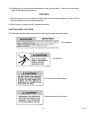
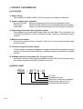
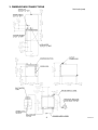
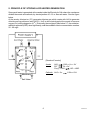
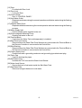
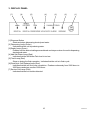
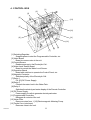
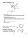
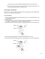
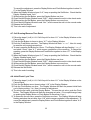
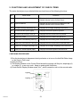
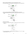
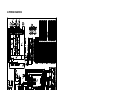
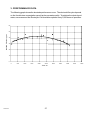
NO.
U8AA-554
ISSUED: DEC. 29, 2000
REVISED:
HOSHIZAKI
WATER ELECTROLYZER
MODEL
ROX-20TA-U
SERVICE MANUAL
CONTENTS
PAGE
I. GENERAL INFORMATION -------------------------------------------------------------------------1. SAFETY INSTRUCTIONS -----------------------------------------------------------------------2. PRODUCT INFORMATION ---------------------------------------------------------------------[a] FEATURES ------------------------------------------------------------------------------------[b] MODEL NAME --------------------------------------------------------------------------------3. DIMENSIONS/CONNECTIONS----------------------------------------------------------------4. FEATURES OF STRONG ACID WATER----------------------------------------------------5. PRINCIPLE OF STRONG ACID WATER GENERATION ---------------------------------
1
1
3
3
3
4
5
6
II. CONSTRUCTION ------------------------------------------------------------------------------------- 7
1. GENERAL ------------------------------------------------------------------------------------------- 7
2. CONTROL PANEL -------------------------------------------------------------------------------- 9
3. DISPLAY PANEL---------------------------------------------------------------------------------- 10
4. CONTROL BOX ----------------------------------------------------------------------------------- 11
5. REMOTE CONTROLLER (OPTION) --------------------------------------------------------- 12
6. WATER TANK FLOAT SWITCHES (OPTION)---------------------------------------------- 12
7. OUTLET VALVES (OPTION) ------------------------------------------------------------------- 12
III. OPERATING INSTRUCTIONS -------------------------------------------------------------------- 13
1. FUNCTIONS AND ADJUSTMENT OF SET ITEMS --------------------------------------- 13
2. FUNCTIONS AND ADJUSTMENT OF CHECK ITEMS ---------------------------------- 21
3. OPERATION FLOW CHART ------------------------------------------------------------------- 24
IV. TECHNICAL INFORMATION --------------------------------------------------------------------- 25
1. WATER CIRCUIT ---------------------------------------------------------------------------------- 25
2. WIRING DIAGRAM ------------------------------------------------------------------------------- 26
3. PERFORMANCE DATA------------------------------------------------------------------------- 27
V. SERVICE INFORMATION ------------------------------------------------------------------------- 29
1. MAINTENANCE/INSPECTION ---------------------------------------------------------------- 29
2. SERVICE DIAGNOSIS -------------------------------------------------------------------------- 31
U8AA5540012
I. GENERAL INFORMATION
1. SAFETY INSTRUCTIONS
The following instructions contain important safety precautions and should be strictly observed.
The terms used here are defined as follows:
WARNING: There is a possibility of death or serious injury for the service person and a third
party or the user due to improper service operations or defects in serviced
products.
CAUTION:
There is possibility of injury of the service person and a third party or the user or
damage to their property* due to improper service operations or defects in
serviced products.
* The term “damage to their property” here refers to extensive damage to houses, household
effects, livestock and pets.
WARNING
1. When there is no need to energize the unit during disassembly or cleaning, be sure to
unplug the unit or disconnect the main power supply before servicing the unit to prevent
electric shocks.
2. If the unit must be energized for inspection of the electric circuit, use rubber gloves to avoid
contact with any live parts, which may result in electric shocks.
3. Check for proper earth connections, and repair if necessary to prevent electric shocks.
4. Always use service parts intended for the applicable model for replacement of defective
parts. Use proper tools to secure the wiring. Otherwise abnormal operation or trouble
may occur and cause electric leaks or fire.
5. Check for proper part installations, wiring conditions and soldered or solderless terminal
connections to avoid smoke, fire or electric shocks.
6. Be sure to replace damaged or deteriorated power cords and lead wires to prevent electric
shocks, flames or smoke.
7. Lead wires using solderless terminals or the like must be bound with their closed ends up
to avoid entrance of moisture that could lead to electric leaks or fire.
8. After servicing, always use a megohmmeter (DC500V) to check for the insulation resistance
of minimum 1 megohm between the live part (attachment plug) and the dead metal part
(earth terminal). Negligence in checking may cause electric leaks or shocks.
9. Do not service the electrical parts with wet hands to prevent electric leaks or shocks.
U8AA5540012
1
10. Always ask the user to keep children away from the work area. They may be injured by
tools or disassembled products.
CAUTION
1. After servicing, be sure to check for water leaks from the water supply and drain lines to
prevent wetting the surrounding properties.
2. After servicing, always check for proper operation.
CAUTION LABEL LOCATION
The following caution labels are attached where special care should be taken.
On top panel
Inside door
On remote controller (option)
On bottom front of control box
2
U8AA5540012
2. PRODUCT INFORMATION
[a] FEATURES
1) Space saving
The compact unit (W280 x D400 x H310 mm) allows for installation under sink.
2) Various optional parts available
Remote Controller: Makes the dispensing section remotely operable at hand.
Float Switch:
Detects the tank water level to automatically start/stop operation.
Outlet Valve:
Allows use of electrolyzed water stored in the tank, as required.
3) Concentrated salt water direct injection system
Direct addition of concentrated salt water held in the Salt Water Tank (accessory) into
the water flow requires no tank for diluted salt water, resulting in reducing the space
required.
4) Built-in current sensor
No salt concentration sensor is required. The built-in current sensor provides highly
accurate control.
5) Constant-voltage DC power supply
Current control by a constant-voltage power supply uses the salt concentration to correct
reduction of the electrolyzation efficiency, resulting in stable concentration of available
chlorine.
6) Available chlorine concentration 20 - 30 mg/L or more
Acid water contains undissociated hypochlorous acid (HOCl) which sanitizes faster
than sodium hypochlorite (NaOCl) and does not remain.
[b] MODEL NAME
ROX - 20 T A - U
For USA
Development Order
Table-top or under-sink installation
Maximum flow rate (x0.1L/min)
Hoshizaki Water Electrolyzer
U8AA5540012
3
3. DIMENSIONS/CONNECTIONS
Unit: inch (mm)
4
U8AA5540012
4. FEATURES OF STRONG ACID WATER
Electrolyzed water (electrolyzed functional water) is a solution with useful functions caused by
electrolyzation of thin salt water or tap water. Different conditions of electrolyzation produce
various kinds of electrolyzed water whose applications are categorized into: [1] sanitation
(strong acid water, strong alkaline water, weak acid water, hypochlorous acid water) and [2]
consumption (alkaline ionized water). The Water Electrolyzer ROX-20TA-U produces strong
acid water and strong alkaline water in the category [1].
Strong acid water has the following features:
(1) Main Ingredient:
(2) pH:
(3) Oxidation-Reduction Potential*2):
(4) Available Chlorine Concentration*3):
(5) Color:
(6) Others:
Hypochlorous acid*1)
2.2 - 2.7
Max. +1100mV
20 - 60mg/L
None
Stimulative smell of chlorine
(contains un-electrolyzed salt)
*1) Hypochlorous acid (HOCl)
Dissolution of chlorine gas in water generates hypochlorous acid (HOCl) whose ratio to
hypochlorous acid ion (ClO-) varies with the pH of water. In the pH range for strong acid
water, much more HOCl than ClO- exists. Both HOCl and ClO- have a bactericidal
effect, but HOCl is much stronger than ClO-.
*2) Oxidation-Reduction Potential (ORP)
Oxidizing (or reducing) effect of the solution. The larger positive number indicates the
higher oxidizing effect.
*3) Available Chlorine Concentration
Chlorine concentration contributing to the bactericidal activity. It indicates the amount
of chlorine corresponding to iodine isolated in the following reaction:
NaOCl + 2Kl + 2CH3•COOH
I2 + 2CH3•COOK + NaCl + H2O
Note: The terms related to chlorine are defined as below:
Residual Chlorine:
Remaining chlorine as the result of excessive chlorine addition into
tap water to optimize the bactericidal effect of chlorination.
Free Chlorine:
Chlorine (Cl2), hypochlorous acid (HOCl) and hypochlorous acid ion
(OCl-) generated by dissolution of chlorine in water.
Combined Chlorine: Chloramine (NH2Cl, NHCl2, NCl3) generated by dissolution of chlorine
in water containing ammoniate or organic nitride. Combined chlorine
is stable and durable, but not so effective in a quick bactericidal activity.
Available Chlorine:
U8AA5540012
Combination of free chlorine and combined chlorine.
5
5. PRINCIPLE OF STRONG ACID WATER GENERATION
Strong acid water is generated at the anode inside the Electrolytic Cell where the membrane
divides the anode and cathode, by electrolyzation of 0.1% or less salt water. See the figure
below.
At the anode, chlorine ion (Cl-) generates chlorine gas which reacts with H2O to generate
chloride and hypochlorous acid (HOCl). H2O is also electrolyzed at the anode to become
oxygen (O2) and hydrogen ion (H+). Eventually, the anolyte pH falls below 2.7, the oxidationreduction potential (ORP) rises significantly, and the available chlorine concentration reaches
20 - 60 mg/L.
[Reaction Formula]
Anode
H2O
1/2O2 + H+ + 2e2ClCl2 + 2eCl2(aq) + H2O
HCl + HOCl
Cathode H2O + 2e-
6
1/2H2 + OH-
U8AA5540012
II. CONSTRUCTION
1. GENERAL
[17]
[16]
[4]
[6]
[5]
[18]
[3]
[7]
[19]
[2]
[1]
[20]
[21]
[8]
[15] [27]
[9]
[10]
[11]
[22]
[14]
[26]
[12]
[13]
[25]
[24]
[1] Display Panel
See “3. DISPLAY PANEL“.
[2] Lamp Board
Board with lamps indicating unit status.
[3] Control Box
See “4. CONTROL BOX”.
[4] Flow Switching Valve
Changes the flow direction of electrolyzed water.
[5] Microswitch [Direction]
Senses the direction of the Flow Switching Valve.
[6] Microswitch [Location]
Senses the location of the Flow Switching Valve.
[7] Gear Motor
Rotates the Impeller inside the Flow Switching Valve.
[8] Water Valve
Supplies potable water to the Electrolytic Cell.
[9] Flow Rate Sensor
Senses potable water flow.
[10] Surge Absorber
Interrupts a temporary voltage surge.
[11] Electrolytic Cell
Electrolyzes diluted salt water and generates acid and alkaline water.
[12] Leg
Not adjustable.
U8AA5540012
7
[23]
[13] Door
Provided with Door Lock.
[14] Door Lock
Locks the Door.
[15] Control Panel
See “2. CONTROL PANEL”.
[16] Acid Water Outlet
Dispenses acid water during the normal operation and alkaline water during the flushing
process.
[17] Alkaline Water Outlet
Dispenses alkaline water during the normal operation and acid water during the flushing
process.
[18] Water Supply Inlet
Inlet for potable water supplied to the unit.
[19] Electromagnetic Metering Pump
Supplies salt water to the unit.
[20] Terminal Block
Used when the Water Tank (sold separately) is installed.
[21] Rear Panel (not shown)
Removed when the Water Tank Float Switches are connected to the Terminal Block or
the Remote Controller is connected to the Control Box.
[22] Blind Bushing
Removed when the Water Tank Float Switches are connected to the Terminal Block or
the Remote Controller is connected to the Control Box.
[23] Power Supply Cord
Flexible cord with a grounding conductor and grounding type attachment plug.
[24] Drain Cap
Used for draining the pipes.
[25] Salt Water Hose
Includes the PVC hose and the Water Level Sensor.
[26] Water Level Sensor
Senses the level of salt water inside the Salt Water Tank.
[27] Salt Water Filter
Removes foreign substances in salt water.
8
U8AA5540012
2. CONTROL PANEL
[1]
[10]
[2]
[3]
[4]
[5]
[9]
[6]
[7]
[8]
[1] Display Window
Displays the operation time, amperage or voltage during the normal operation and
error codes in case of trouble.
[2] Operation Time Lamp
Display Window displays operation time (h) when this lamp is on.
[3] Amperage Lamp
Display Window displays amperage (A) when this lamp is on.
[4] Voltage Lamp
Display Window displays voltage (V) when this lamp is on.
[5] Display Select Button
Switches the display of the Display Window.
[6] Flush Button
Functions as a switch to flush the pipes beyond the acid and alkaline water outlets.
[7] Set Button
Only qualified service personnel or installer may press this button to adjust various set
values.
[8] Amperage Control Volume
Only qualified service personnel may turn this control to change the set amperage.
[9] Voltage Control Volume
Only qualified service personnel may turn this control to change the set voltage.
[10] Power Switch
Turns the unit on and off.
U8AA5540012
9
3. DISPLAY PANEL
[7]
[6]
[5]
[4]
[3]
[2]
[1]
[1] Dispense Button
Starts and stops dispensing electrolyzed water.
[2] Dispensing Lamp (Green)
Indicates that the unit is producing water.
[3] Ready Lamp (Green)
Flashes until the desired settings are achieved and stays on when the unit is dispensing
electrolyzed water.
[4] Add Salt Water Lamp (Red)
Indicates that the Salt Water Tank level is too low.
[5] Flush Lamp (Red)
Stays on during the flush operation. Indicates that the unit is in flush cycle.
[6] Electrolytic Cell Replace Lamp (Red)
Indicates that the cell life is near completion. Flashes continuously from 2900 hours to
3000 hours and stays on after 3000 hours.
[7] Service Call Lamp (Red)
Indicates that there is trouble detected.
10
U8AA5540012
4. CONTROL BOX
[1]
[2]
[3]
[4]
[13]
[5]
[12]
[6]
[11]
[10]
[9]
[8]
[7]
[1] Switching Regulator
Supplies power to start the Programmable Controller, etc.
[2] Noise Board
Board to remove noise in the unit.
[3] Current Sensor
Reads amperage in the Electrolytic Cell.
[4] Water Level Sensor Board
Board to control the Water Level Sensor.
[5] Operation Board
Board with switches to operate the Control Panel, etc.
[6] Magnetic Contactor
Switches polarity of the Electrolytic Cell.
[7] Relay 1
For [10] DC Power Supply.
[8] Relay 2
Controls the water level in the Water Tank.
[9] Relay 3
Switches the electrolyzed water display of the Remote Controller.
[10] DC Power Supply
Power supply for cells to generate electrolyzed water.
[11] Programmable Controller
Manages all controls of the unit.
[12] Noise Filter
Removes noise from 1. [19] Electromagnetic Metering Pump.
[13] Ferrite Core (not shown)
Removes noise in the unit.
U8AA5540012
11
5. REMOTE CONTROLLER (OPTION)
[1]
[2]
[3]
[4]
[5]
[1] Ready Lamp (Green)
Flashes until the desired settings are achieved and stays on when the unit is dispensing
electrolyzed water.
[2] Add Salt Water Lamp (Red)
Indicates that the Salt Water Tank level is too low.
[3] Electrolyzed Water Lamp (Green)
The upper lamps will function during the normal operation. Alkaline water is dispensed
from the left outlet and acid from the right. The lower lamps will function during the flush
operation only. Acid water is dispensed from the left outlet and alkaline water from the
right.
[4] Dispense Button
Starts and stops dispensing electrolyzed water.
[5] Electrolyzed Water Outlet
Transports electrolyzed water.
6. WATER TANK FLOAT SWITCHES (OPTION)
Includes the Upper and Lower Acid Water Tank Level
Float Switches and Upper and Lower Alkaline Water
Tank Level Float Switches.
7. OUTLET VALVES (OPTION)
Connected with the Electrolyzed Water Outlets (for
acid and alkaline water outlets) on the Water Tank.
Use as needed.
12
U8AA5540012
III. OPERATING INSTRUCTIONS
1. FUNCTIONS AND ADJUSTMENT OF SET ITEMS
The water electrolyzer is provided with the nine set items of the following functions:
Set Items
Functions
No.
12345678901234567890123456789012123456789012345678901234567890121234567890123456789012345
12345678901234567890123456789012123456789012345678901234567890121234567890123456789012345
12345678901234567890123456789012123456789012345678901234567890121234567890123456789012345
12345678901234567890123456789012123456789012345678901234567890121234567890123456789012345
Adjustment is required if the electrode lifecycle gets longer
A1 Cell Lifecycle (h)
12345678901234567890123456789012123456789012345678901234567890121234567890123456789012345
12345678901234567890123456789012123456789012345678901234567890121234567890123456789012345
3000
8000
(Initial: 3000 h).
12345678901234567890123456789012123456789012345678901234567890121234567890123456789012345
12345678901234567890123456789012123456789012345678901234567890121234567890123456789012345
A2
Amperage (A)
0.0 - 18.0
Changes the pH value (Initial: 14.0 A).
To increase the pH value, raise the amperage.
Changes the available chlorine concentration (Initial: 10.0 V).
A3 Voltage (V)
0.0
18.0
To reduce the residual chlorine concentration, raise the voltage.
123456789012345678901234567890121234567890123456789012345678901212345678901234567890123456
123456789012345678901234567890121234567890123456789012345678901212345678901234567890123456
123456789012345678901234567890121234567890123456789012345678901212345678901234567890123456
123456789012345678901234567890121234567890123456789012345678901212345678901234567890123456
A4 Cell Reverse Time (h) Adjustment is required if the electrode lifecycle gets longer
123456789012345678901234567890121234567890123456789012345678901212345678901234567890123456
123456789012345678901234567890121234567890123456789012345678901212345678901234567890123456
0 - 150
(Initial: 12 h, 0 means no reversal).
123456789012345678901234567890121234567890123456789012345678901212345678901234567890123456
123456789012345678901234567890121234567890123456789012345678901212345678901234567890123456
123456789012345678901234567890121234567890123456789012345678901212345678901234567890123456
123456789012345678901234567890121234567890123456789012345678901212345678901234567890123456
123456789012345678901234567890121234567890123456789012345678901212345678901234567890123456
Changes the reaction to the varying amount of additional
A5 Amperage
123456789012345678901234567890121234567890123456789012345678901212345678901234567890123456
123456789012345678901234567890121234567890123456789012345678901212345678901234567890123456
Accumulation
Time
(s)
concentrated salt water (Initial: 3 s). To delay the amperage
123456789012345678901234567890121234567890123456789012345678901212345678901234567890123456
123456789012345678901234567890121234567890123456789012345678901212345678901234567890123456
123456789012345678901234567890121234567890123456789012345678901212345678901234567890123456
1
90
feedback reaction, extend the time setting.
123456789012345678901234567890121234567890123456789012345678901212345678901234567890123456
Storage Mode/
Hand-washing Mode
Chooses between hand-washing mode using the optional
remote controller and storage mode to store water in the tank
(Initial: hand-washing mode).
12345678901234567890123456789012123456789012345678901234567890121234567890123456789012345
12345678901234567890123456789012123456789012345678901234567890121234567890123456789012345
12345678901234567890123456789012123456789012345678901234567890121234567890123456789012345
12345678901234567890123456789012123456789012345678901234567890121234567890123456789012345
Resets the built-in timer for replacing the Electrolytic Cell.
A7 Cell Running/
12345678901234567890123456789012123456789012345678901234567890121234567890123456789012345
12345678901234567890123456789012123456789012345678901234567890121234567890123456789012345
Reverse Time Reset
12345678901234567890123456789012123456789012345678901234567890121234567890123456789012345
12345678901234567890123456789012123456789012345678901234567890121234567890123456789012345
12345678901234567890123456789012123456789012345678901234567890121234567890123456789012345
12345678901234567890123456789012123456789012345678901234567890121234567890123456789012345
12345678901234567890123456789012123456789012345678901234567890121234567890123456789012345
Changes the time to supply water for flushing away nonA8 Initial Flush Cycle (s)
12345678901234567890123456789012123456789012345678901234567890121234567890123456789012345
12345678901234567890123456789012123456789012345678901234567890121234567890123456789012345
0
120
electrolyzed water in the Electrolytic Cell in the initial operation
12345678901234567890123456789012123456789012345678901234567890121234567890123456789012345
12345678901234567890123456789012123456789012345678901234567890121234567890123456789012345
12345678901234567890123456789012123456789012345678901234567890121234567890123456789012345
(Initial: 3 s).
12345678901234567890123456789012123456789012345678901234567890121234567890123456789012345
12345678901234567890123456789012123456789012345678901234567890121234567890123456789012345
12345678901234567890123456789012123456789012345678901234567890121234567890123456789012345
12345678901234567890123456789012123456789012345678901234567890121234567890123456789012345
A9 Automatic Dispensing Adjusts the dispensing time for automatic dispensing control
12345678901234567890123456789012123456789012345678901234567890121234567890123456789012345
12345678901234567890123456789012123456789012345678901234567890121234567890123456789012345
Control 10 s - 4 m
(Initial: continuous).
12345678901234567890123456789012123456789012345678901234567890121234567890123456789012345
12345678901234567890123456789012123456789012345678901234567890121234567890123456789012345
12345678901234567890123456789012123456789012345678901234567890121234567890123456789012345
Continuous: Continuously dispenses until the Dispensing
12345678901234567890123456789012123456789012345678901234567890121234567890123456789012345
12345678901234567890123456789012123456789012345678901234567890121234567890123456789012345
Button is pushed for the second time.
12345678901234567890123456789012123456789012345678901234567890121234567890123456789012345
12345678901234567890123456789012123456789012345678901234567890121234567890123456789012345
Automatic:
Automatically stops when the adjusted time has
12345678901234567890123456789012123456789012345678901234567890121234567890123456789012345
12345678901234567890123456789012123456789012345678901234567890121234567890123456789012345
passed
since the Dispensing Button is pushed.
12345678901234567890123456789012123456789012345678901234567890121234567890123456789012345
12345678901234567890123456789012123456789012345678901234567890121234567890123456789012345
A6
IMPORTANT
1. The set items A1, A4, A5, A8 and A9 should not be changed unless directed by
an engineer.
2. The set item A7 should be used only when the Electrolytic Cell is replaced.
Note: 1. The set amperage and voltage can be changed just by turning each control volume.
For more accurate adjustment, however, always use the A2 and A3 adjust modes
U8AA5540012
13
and turn the volume while watching the Display Window on the Control Panel.
2. Do not change the amperage and voltage extremely from the initial set values. The
unit may shut down by the error code E42 or E43.
ADJUSTMENT PROCEDURE
Adjust the above set items while electrolyzed water is being dispensed, the Add Salt Water
Lamp is on, or the Service Call Lamp is on.
A1: Cell Lifecycle
1) Run the electrolyzer to dispense electrolyzed water or to turn on the Add Salt Water Lamp
or the Service Call Lamp.
2) Open the Door.
3) The Display Window on the Control Panel shows the present cell lifecycle, amperage (A)
or voltage (V), or an error code. Keep on pushing the Set Button.
4) Check that the Display Window reads “Nor.”, which means the unit is in the normal mode.
Lighting
Lighting
5) Keep on pushing the Set Button, and press the Display Button one time.
6) Check that the Display Window reads “AdJ.”, which means the unit is in the adjust mode.
Lighting
Flashing
14
U8AA5540012
7) Release the Set Button.
8) Check that the Display Window reads “A 1”, which means the unit is in the adjust mode
No. 1.
Lighting
Lighting
9) Push the Flush Button one time. The Display Window will flash the present cell lifecycle
(factory setting: 3000 h). Now it is ready for adjustment.
10) To raise the set value, push the Display Button. To lower the set value, push the Flush
Button. The Display Window will flash the changing set value. (For a rapid change, keep
on pushing the Display Button or Flush Button for more than 1 sec.)
11) To determine the set value, press the Set Button one time. The Display Window will stop
flashing and show the set value, then “A 1” which means completion of the adjustment. To
cancel the adjustment, press the Display Button and Flush Button together to show “A 1”
in the Display Window.
12) When the Display Window shows “A 1”, keep on pushing the Set Button. Check that the
Display Window reads “AdJ.”
13) While pushing the Set Button, press the Display Button one time.
14) Check that the Display Window reads “CHE.”, which means the unit is in the check mode.
Lighting
Flashing
15) While pushing the Set Button, press the Display Button one more time.
16) Check that the Display Window reads “Nor.”, which means the unit is in the normal mode.
17) Release the Set Button.
18) This is the end of adjustment.
U8AA5540012
15
A2: Amperage
1) Follow the steps 1) to 8) in “A1: Cell Lifecycle” to show “A 1” in the Display Window on the
Control Panel.
2) Push the Set Button one time to show “A 2” in the Display Window.
3) Push the Flush Button one time. The Display Window will flash the present amperage
(factory setting: 14.0 A). Now it is ready for adjustment.
Flashing
Flashing
4) Use a precision screwdriver to turn the Amperage Control Volume. The Display Window
will flash the changing set value.
5) When the Display Window shows the desired set value, push the Set Button one time.
The Display Window will stop flashing and show the set value, then “A 2” which means
completion of the adjustment.
6) When the Display Window shows “A 2”, keep on pushing the Set Button. Check that the
Display Window reads “AdJ.”
7) While pushing the Set Button, press the Display Button one time.
8) Check that the Display Window reads “CHE.”, which means the unit is in the check mode.
9) While pushing the Set Button, press the Display Button one more time.
10) Check that the Display Window reads “Nor.”, which means the unit is in the normal mode.
11) Release the Set Button.
12) This is the end of adjustment.
A3: Voltage
1) Follow the steps 1) to 8) in “A1: Cell Lifecycle” to show “A 1” in the Display Window on the
Control Panel.
2) Push the Set Button two times to show “A 3” in the Display Window.
3) Push the Flush Button one time. The Display Window will flash the present voltage (factory
setting: 10.0 V). Now it is ready for adjustment.
4) Use a precision screwdriver to turn the Voltage Control Volume. The Display Window will
flash the changing set value.
5) When the Display Window shows the desired set value, push the Set Button one time.
The Display Window will stop flashing and show the set value, then “A 3” which means
completion of the adjustment.
6) When the Display Window shows “A 3”, keep on pushing the Set Button. Check that the
Display Window reads “AdJ.”
16
U8AA5540012
7) While pushing the Set Button, press the Display Button one time.
8) Check that the Display Window reads “CHE.”, which means the unit is in the check mode.
9) While pushing the Set Button, press the Display Button one more time.
10) Check that the Display Window reads “Nor.”, which means the unit is in the normal mode.
11) Release the Set Button.
12) This is the end of adjustment.
A4: Cell Reverse Time
1) Follow the steps 1) to 8) in “A1: Cell Lifecycle” to show “A 1” in the Display Window on the
Control Panel.
2) Push the Set Button three times to show “A 4” in the Display Window.
3) Push the Flush Button one time. The Display Window will flash the present cell reverse
time (factory setting: 12 h). Now it is ready for adjustment.
4) To raise the set value, push the Display Button. To lower the set value, push the Flush
Button. The Display Window will flash the changing set value. (For a rapid change, keep
on pushing the Display Button or Flush Button for more than 1 sec.)
5) To determine the set value, press the Set Button one time. The Display Window will stop
flashing and show the set value, then “A 4” which means completion of the adjustment. To
cancel the adjustment, press the Display Button and Flush Button together to show “A 4”
in the Display Window.
6) When the Display Window shows “A 4”, keep on pushing the Set Button. Check that the
Display Window reads “AdJ.”
7) While pushing the Set Button, press the Display Button one time.
8) Check that the Display Window reads “CHE.”, which means the unit is in the check mode.
9) While pushing the Set Button, press the Display Button one more time.
10) Check that the Display Window reads “Nor.”, which means the unit is in the normal mode.
11) Release the Set Button.
12) This is the end of adjustment.
A5: Amperage Accumulation Time
1) Follow the steps 1) to 8) in “A1: Cell Lifecycle” to show “A 1” in the Display Window on the
Control Panel.
2) Push the Set Button four times to show “A 5” in the Display Window.
3) Push the Flush Button one time. The Display Window will flash the present amperage
accumulation time (factory setting: 3 s). Now it is ready for adjustment.
4) To raise the set value, push the Display Button. To lower the set value, push the Flush
Button. The Display Window will flash the changing set value. (For a rapid change, keep
on pushing the Display Button or Flush Button for more than 1 sec.)
5) To determine the set value, press the Set Button one time. The Display Window will stop
flashing and show the set value, then “A 5” which means completion of the adjustment. To
cancel the adjustment, press the Display Button and Flush Button together to show “A 5”
in the Display Window.
6) When the Display Window shows “A 5”, keep on pushing the Set Button. Check that the
Display Window reads “AdJ.”
U8AA5540012
17
7) While pushing the Set Button, press the Display Button one time.
8) Check that the Display Window reads “CHE.”, which means the unit is in the check mode.
9) While pushing the Set Button, press the Display Button one more time.
10) Check that the Display Window reads “Nor.”, which means the unit is in the normal mode.
11) Release the Set Button.
12) This is the end of adjustment.
A6: Storage Mode/Hand-washing Mode
1) Follow the steps 1) to 8) in “A1: Cell Lifecycle” to show “A 1” in the Display Window on the
Control Panel.
2) Push the Set Button five times to show “A 6” in the Display Window.
3) Push the Flush Button one time. The Display Window will flash the following patterns:
HANd --------- With the Remote Controller installed
POOL -------- With the Water Tank installed
SFt.H --------- Do not set.
SFt.P --------- Do not set.
Flashing
Flashing
Flashing
Flashing
4) Push the Display Button or Flush Button. The Display Window will flash the other set
mode.
5) To determine the set mode, press the Set Button one time. The Display Window will stop
flashing and show the set mode, then “A 6” which means completion of the adjustment.
18
U8AA5540012
To cancel the adjustment, press the Display Button and Flush Button together to show “A
6” in the Display Window.
6) When the Display Window shows “A 6”, keep on pushing the Set Button. Check that the
Display Window reads “AdJ.”
7) While pushing the Set Button, press the Display Button one time.
8) Check that the Display Window reads “CHE.”, which means the unit is in the check mode.
9) While pushing the Set Button, press the Display Button one more time.
10) Check that the Display Window reads “Nor.”, which means the unit is in the normal mode.
11) Release the Set Button.
12) This is the end of adjustment.
A7: Cell Running/Reverse Time Reset
1) Follow the steps 1) to 8) in “A1: Cell Lifecycle” to show “A 1” in the Display Window on the
Control Panel.
2) Push the Set Button six times to show “A 7” in the Display Window.
3) Push the Flush Button one time. The Display Window will flash “ ≡ ≡ ≡ ≡”. Now it is ready
to reset the cell running/reverse time.
4) To reset, press the Set Button for 10 sec. The Display Window will stop flashing “ ≡ ≡ ≡ ≡”
and show “Good”, then “A 7” which means completion of the resetting. To cancel the
resetting, press the Display Button and Flush Button together to show “A 7” in the Display
Window.
5) When the Display Window shows “A 7”, keep on pushing the Set Button. Check that the
Display Window reads “AdJ.”
6) While pushing the Set Button, press the Display Button one time.
7) Check that the Display Window reads “CHE.”, which means the unit is in the check mode.
8) While pushing the Set Button, press the Display Button one more time.
9) Check that the Display Window reads “Nor.”, which means the unit is in the normal mode.
10) Release the Set Button.
11) This is the end of resetting.
A8: Initial Flush Cycle Time
1) Follow the steps 1) to 8) in “A1: Cell Lifecycle” to show “A 1” in the Display Window on the
Control Panel.
2) Push the Set Button seven times to show “A 8” in the Display Window.
3) Push the Flush Button one time. The Display Window will flash the present initial flash
cycle (factory setting: 3 s). Now it is ready for adjustment.
4) To raise the set value, push the Display Button. To lower the set value, push the Flush
Button. The Display Window will flash the changing set value. (For a rapid change, keep
on pushing the Display Button or Flush Button for more than 1 sec.)
5) To determine the set value, press the Set Button one time. The Display Window will stop
flashing and show the set value, then “A 8” which means completion of the adjustment. To
cancel the adjustment, press the Display Button and Flush Button together to show “A 8”
in the Display Window.
U8AA5540012
19
6) When the Display Window shows “A 8”, keep on pushing the Set Button. Check that the
Display Window reads “AdJ.”
7) While pushing the Set Button, press the Display Button one time.
8) Check that the Display Window reads “CHE.”, which means the unit is in the check mode.
9) While pushing the Set Button, press the Display Button one more time.
10) Check that the Display Window reads “Nor.”, which means the unit is in the normal mode.
11) Release the Set Button.
12) This is the end of adjustment.
A9: Automatic Dispensing Control
1) Follow the steps 1) to 8) in “A1: Cell Lifecycle” to show “A 1” in the Display Window on the
Control Panel.
2) Push the Set Button eight times to show “A 9” in the Display Window.
3) Push the Flush Button one time. The Display Window will flash the present automatic
dispensing control (factory setting: continuous “CoNt.”). Now it is ready for adjustment.
4) To raise the set value, push the Display Button. To lower the set value, push the Flush
Button. The Display Window will flash the changing set value. (For a rapid change, keep
on pushing the Display Button or Flush Button for more than 1 sec.)
5) To determine the set value, press the Set Button one time. The Display Window will stop
flashing and show the set value, then “A 9” which means completion of the adjustment. To
cancel the adjustment, press the Display Button and Flush Button together to show “A 9”
in the Display Window.
6) When the Display Window shows “A 9”, keep on pushing the Set Button. Check that the
Display Window reads “AdJ.”
7) While pushing the Set Button, press the Display Button one time.
8) Check that the Display Window reads “CHE.”, which means the unit is in the check mode.
9) While pushing the Set Button, press the Display Button one more time.
10) Check that the Display Window reads “Nor.”, which means the unit is in the normal mode.
11) Release the Set Button.
12) This is the end of adjustment.
Note: If the automatic dispensing control setting is short, the unit may stop automatically in
the middle of the next adjustment. In this case, adjust the setting as follows:
1) Turn on the Power Switch. While the Display Window shows nothing, push the Flush
Button for more than 10 sec.
2) Select the desired mode, and adjust the setting.
20
U8AA5540012
2. FUNCTIONS AND ADJUSTMENT OF CHECK ITEMS
The water electrolyzer is provided with the ten check items of the following functions:
No.
Functions
Check Items
C1
Output Conditions
Displays all the present output conditions in the
Display Window on the Control Panel.
C2
Input Conditions
Displays all the present input conditions in the
Display Window on the Control Panel.
C3
Present Average Amperage (A)
Displays the average amperage at present.
C4
Present Stroke Speed (spm)
Displays the stroke speed at present.
C5
Present Cell Reverse Time (h)
Displays the cell reverse time at present.
C6
Last Error Code
Displays the error code of the last error.
C7
Last Error Cell Running Time (h)
Displays the cell running time of the last error.
C8
Last Error Cell Reverse Time (m)
Displays the cell reverse time of the last error.
C9
Last Error Average Amperage (A)
Displays the average amperage of the last error.
C10
Last Error Stroke Speed (spm)
Displays the stroke speed of the last error.
CHECKING PROCEDURE
1) Run the electrolyzer to dispense electrolyzed water or to turn on the Add Salt Water Lamp
or the Service Call Lamp.
2) Open the Door.
3) The Display Window on the Control Panel shows the present cell lifecycle, amperage (A)
or voltage (V), or an error code. Keep on pushing the Set Button.
4) Check that the Display Window reads “Nor.”, which means the unit is in the normal mode.
Lighting
Lighting
U8AA5540012
21
5) Keep on pushing the Set Button, and press the Display Button one time.
6) Check that the Display Window reads “AdJ.”, which means the unit is in the adjust mode.
Lighting
Flashing
7) Keep on pushing the Set Button, and press the Display Button one more time.
8) Check that the Display Window reads “CHE.”, which means the device is in the check
mode.
Lighting
Flashing
9) Release the Set Button.
10) Check that the Display Window reads “C 1”, which means the device is in the check
mode No. 1.
Lighting
Lighting
11) Push the Display Button. The Display Window will change from “C 1” to “C 2”. Another
push will change “C 2” to “C 3”.
22
U8AA5540012
12) When the desired check item code is displayed, push the Flush Button one time. The
Display Window will show the present check item information.
13) To finish checking, press the Display Button and Flush Button together to show “C 1”, “C
2”... in the Display Window.
14) When the Display Window shows one of those check item codes, keep on pushing the
Set Button. Check that the Display Window reads “CHE.”
15) While pushing the Set Button, press the Display Button one time.
16) Check that the Display Window reads “Nor.”, which means the device is in the normal
mode.
17) Release the Set Button.
18) This is the end of checking.
C1: Output Conditions
The lighting LED shows the applicable output is ON.
Relay X3
Magnet Switch
Relay X1
Gear Motor
None
Pulse signal to
Metering Pump
Water Valve
Output to DC power
supply CNT-TOG
C2: Input Conditions
The lighting LED shows the applicable input is ON.
Direction Microswitch
Location Microswitch
Display Button
Flow Rate Switch
None
Set Button
Max. Water Level
(Float Switch ON)
U8AA5540012
23
Flush Button
Level Sensor
3. OPERATION FLOW CHART
Normal Mode (Nor.)
2
2
[1] Cell Running Time (h)
1
[2] Amperage (A)
[3] Voltage (V)
2
Adjust Mode (AdJ.)
Check Mode (CHE.)
3
A1 Cell Lifecycle (h)
ditto
A3 Set Voltage (V)
ditto
C3 Present Average Amperage (A)
ditto
A4 Cell Reverse Time (h)
ditto
C4 Present Stroke Speed (spm)
ditto
A5 Amperage Accumulation
Time (h)
A6 Storage Mode/
Hand-washing Mode
A7 Cell Running/Reverse
Time Reset
A8 Initial Flush Cycle (s)
ditto
C5 Present Cell Reverse Time (h)
ditto
ditto
C6 Last Error Code
ditto
ditto
C7 Last Error Cell Running Time (h)
ditto
ditto
C8 Last Error Cell Reverse Time (m) ditto
A9 Automatic Dispensing
Control
ditto
C9 Last Error Average Amperage (A) ditto
A2 Set Amperage (A)
1
3
C1 Output
Conditions
C2 Input Conditions
Set
4
1
Check
5
C10 Last Error Stroke Speed (spm)
ditto
ditto
Operation
1 Press Display Button.
2 Keep on pushing Set Button, and press Display Button.
3 Press Flush Button.
4 Press Set Button. For A7, keep on pushing it for 10 sec.
5 Press Display Button and Flush Button together.
24
U8AA5540012
IV. TECHNICAL INFORMATION
1. WATER CIRCUIT
Pressure
Gauge
Filter
Water
Supply
Pressure Reducing
Valve (2.5kgf/cm2)
Pressure Reducing
Valve (Accessory)
Water Electrolyzer
(ROX-20TA-U)
Water
Softener
Control Box
Water Valve
Flow Rate
Sensor
Metering
Pump
Electrolytic
Cell
Salt
Water
U8AA5540012
25
Remote Controller
or Tank
2. WIRING DIAGRAM
26
U8AA5540012
3. PERFORMANCE DATA
The following graph shows the electrode performance curve. The electrode life cycle depends
on the free chlorine concentration as well as the raw water quality. To optimize the electrolyzed
water, we recommend the Electrolytic Cell should be replaced every 3,000 hours of operation.
60
Available Chlorine <ppm>
50
40
30
20
10
0
0
500
1000
1500
2000
2500
Time <h>
U8AA5540012
27
3000
3500
4000
4500
5000
pH and Amperage
Water Temperature: 25°C
* The above data depends on the water temperature and water quality.
Amperage and Available Chlorine Concentration
Water Temperature: 25°C
* The above data depends on the water temperature and water quality.
28
U8AA5540012
V. SERVICE INFORMATION
1. MAINTENANCE/INSPECTION
Check the following items during maintenance or inspection in normal condition. If any of
them is found abnormal or defective, repair, replace or adjust it properly.
Inspection
Remedy
No.
Item
U8AA5540012
Check
1
Acid Water pH
Within specified range?
Check by pH tester.
2
Alkaline Water pH
Within specified range?
Check by pH tester.
3
Available Chlorine
Concentration (Acid)
Within specified range?
Check by accessory chlorine test
paper or thiosulfuric acid titration.
4
Flow Rate (Acid/Alkaline) Within specified range?
Check by beaker.
5
Ambient Temp.
Within specified range?
Check by thermometer.
6
Water Supply Temp.
Within specified range?
Check by thermometer.
7
Water Supply Pressure
Within specified range?
Check by water pressure gauge.
8
Cell Replace Lamp
Flashing or lighting?
Visually check.
9
Salt Water Tank
No dirt buildup?
No salt deposit at bottom?
Visually check.
Visually check.
10
Filter
Not clogged with dirt?
Visually check.
11
Water Circuit
No water leak?
Visually check.
12
Attachment Plug
Securely plugged in?
Not hot?
Visually check.
Check.
13
Exterior
Clean?
Visually check.
14
Float Switch
Free of scale?
Working properly?
Visually check.
Check for proper operation.
15
Water Softener
Water softened?
Working properly?
Set to regenerate water while
unit is out of service?
Proper amount of salt inside?
Check water sample.
Check.
Check.
Check.
16
Cartridge Filter
Pressure difference within
specified range?
Visually check.
17
Remote Controller
Water outlet not blocked?
Working properly?
Visually check.
Check for proper operation.
18
Labels
Attached firmly in place?
Visually check.
29
[a] Acid Water pH, Alkaline Water pH [No. 1, 2]
Always use the accessory pH test paper or a pH tester on the market to check pH.
Carefully read the instructions provided with the test paper or tester, and use it properly.
[b] Available Chlorine Concentration (Acid) [No. 3]
Always use the accessory test paper or the thiosulfuric acid titration specified below to check
available chlorine concentration.
Carefully read the instructions provided with the test paper, and use it properly.
If the available chlorine concentration is below the specified level (it also depends on the
original water quality), be sure to adjust the amperage and voltage to make the concentration
reach the specified level.
Thiosulfuric Acid Titration
< Instruments >
Erlenmeyer flask (100mL - 200mL)
Measuring cylinder (50mL)
Measuring pipet or syringe (graduated by 0.1 or 0.5mL)
Reagents: Potassium iodide (KI)
Sodium thiosulfate (1/100N)
1) Wash the Erlenmeyer flask, measuring cylinder and measuring pipet with tap water.
2) Take 35.4mL of acid water in the cylinder, and pour it gently into the flask.
3) Put some potassium iodide (two or three grains) into the flask, and stir it lightly. The acid
water will turn orange.
4) Take some sodium thiosulfate (1/100N) with the pipet, and read it.
5) Drop the sodium thiosulfate (1/100N) little by little into the flask while stirring it lightly. When
the acid water starts losing its color, drop the reagent with special care.
6) When the acid water turns from orange into clear, stop dropping the reagent and read the
pipet.
7) The dropping amount (mL) x 10 will be the available chlorine concentration (mg/L). For
example, if the dropping amount is 4.5mL, the available chlorine concentration will be
45mg/L.
[c] Cell Replace Lamp [No. 8]
The flashing Cell Replace Lamp indicates that the Electrolytic Cell has run for 2900 - 3000
hours and should be replaced soon.
The lighting Cell Replace Lamp indicates that the Electrolytic Cell has run for 3000 hours or
more and needs immediate replacement.
[d] Water Softener [No. 15]
Carefully read the instructions provided with the water softener, and use it properly.
Check that the water softener is set to start regeneration while electrolyzed water is not
dispensed (ex. 2:00AM).
30
U8AA5540012
The water softener also needs salt for regeneration. Always add a proper amount of salt into
the water softener. Give the user sufficient instructions to add salt periodically.
[e] Cartridge Filter [No. 16]
Replace the cartridge filter when the pressure gauge readings on the primary side of the
water softener and on the secondary side of the cartridge filter differ by 0.1MPa (1.0kgf/cm2)
or more.
2. SERVICE DIAGNOSIS
When the unit shuts down with the Service Call Lamp lighting:
Lamp Code
Service E11
Call
Problem
Check
After water valve Water Supply
opens, flow rate
sensor does not Water Outlet
detect water flow
Connecting Hose
for 3 sec.
Alkaline Water Line
Service E42
Call
U8AA5540012
Cut off.
Recover.
Blocked.
Unblock.
Crushed or bent.
Release stress.
Scaled up.
Clean.
Unclog.
Water Valve
Clogged.
Unclog.
Connector in bad
contact.
Improve contact.
Defective.
Repair or replace.
Clogged.
Unclog.
Connector in bad
contact.
Improve contact.
Defective.
Repair or replace.
Programmable
Controller
After water valve
closes, flow rate
sensor detects
water flow for 3
sec.
Remedy
Flow Switching Valve Clogged.
Flow Rate Sensor
E14
Possible Cause
Water valve output Repair or replace.
contact defective.
Flow rate sensor
input defective.
Repair or replace.
Water Valve
Clogged.
Unclog.
Flow Rate Sensor
Defective.
Repair or replace.
Metering pump
Salt Water Tank
stroke speed
exceeds 360spm Set Voltage
for 60 sec.
Set Amperage
31
Salt water too thin. Thicken.
Too low.
Raise.
Too high.
Reduce.
Lamp Code
Check
Problem
Filter
Service E42 Metering pump
stroke speed
Call
exceeds 360spm Salt Water Hose
for 60 sec.
E43 Metering pump
stroke speed
does not exceed
10spm for 60
sec.
Service E51 Stroke speed
exceeds last
Call
stroke speed +
10spm for 20
sec.
Dirty.
Clean.
Clogged.
Unclog.
Air inside.
Remove air.
Water Supply
Too much.
Keep within specified
range.
Cell Salt
Concentration
Too high.
Repeat dispensing to
supply water and
lower concentration.
Set Voltage
Too high.
Reduce.
Set Amperage
Too low.
Raise.
Salt Water Tank
Salt water too thick. Thin.
Metering Pump Head Not positioned at
Dial
“E”.
Turn into “E” position.
Salt Water Hose
Air inside.
Remove air.
Clogged.
Unclog.
Filter
Dirty.
Clean.
Salt Water Tank
Salt water too thin.
Thicken.
Switching Power
Supply
Defective.
Repair or replace.
DC power supply
line opened.
Repair.
Connector in bad
contact.
Improve contact.
Parts on board
defective.
Repair or replace.
Relay
Bad contact.
Repair or replace.
Magnetic Contactor
Bad contact.
Repair or replace.
Current Sensor
Defective.
Repair or replace.
Connector in bad
contact or open
circuit.
Improve contact or
repair.
Defective.
Repair or replace.
Connector in bad
contact.
Improve contact.
Control Panel
Backside Board
E52 Abnormal input
from current
sensor
Remedy
Possible Cause
Switching Power
Supply
32
U8AA5540012
Lamp Code
Problem
Check
Possible Cause
Gear Motor
Will not stop.
Service E61 Flow switching
Call
valve direction
microswitch turns Location Microswitch Fails to detect.
ON and OFF 5
times in 2 min.
Remedy
Repair or replace.
Repair or replace.
Microswitch
E62 Programmable
controller outputs
to flow switching
valve gear motor
for 20 sec.
Fails to detect.
Repair or replace.
E65 After gear motor Gear Motor
stops, location
microswitch turns
ON.
Overrun.
Repair or replace.
* When restarting the electrolyzer after a shutdown for some error, check the amperage and
voltage on the electrolytic cell with an ammeter and voltmeter (not those provided on the
electrolyzer). If the voltage reading is normal but the amperage is still low, the salt water
inlet can be clogged or the salt water may be too thin. If both amperage and voltage are too
low, check for abnormal DC power supply or a bad contact of the relay or magnetic contactor.
* The electrolyzer may also shut down for some error when the flow rate varies for acid water
and alkaline water because of different piping resistance (ex. connecting hose crushed or
one of the water outlets under water). Even if the electrolyzer is in operation, varying flow
rate may cause low pH and chlorine concentration. Keep a constant flow rate by balancing
the piping resistance.
* The amperage varies with the salt water concentration and metering pump stroke speed.
When restarting the electrolyzer after a shutdown for some error, check the change in
amperage and the metering pump operation.
U8AA5540012
33
HOSHIZAKI ELECTRIC CO., LTD.
3-16 MINAMIYAKATA, SAKAE, TOYOAKE,
AICHI 470-1194 JAPAN
PHONE: 0562-97-2111