1
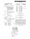
INSTALLATION INSTRUCTIONS FOR THE TRAINED SERVICE TECHNICIAN
APPLICATION
Thesethermostats
systems as follows:
and subbases provide 24 to 30 Vat control for two-stage
MODEL
I
CHANGEOVER
Y594G (T874GIQ674F)
Automatic (Heat or Cool)
T874RlQ674L
Manual
1
heating and one-stage cooling heat pump
SYSTEM SWITCHING
1
FAN SWITCHING
OFF-EM.HT.-HEATAUTO-COOL
1
EM.HT.-HEAT-OFF-COOL
AUTO-ON
1
AUTO-ON
OPERATION
On a two-heat thermostat, the two stages of heat
“make” sequentially as the temperature drops. “Make”
refers to the mercury switch initiating a call for heat or
COOL
There is about 2 F [1 .I C] between stages so that the
second stage (auxiliary heat) makes only when the first
stage can’t handle the load. This is the interstage
differential.
Three LEDs (light-emitting diodes) are included on the
subbase. The red CHECK LED lights when something
needs to be checked or done to maintain efficient
operation of the system. See your heating system
instructions to find out specifically what the CHECK LED
signifies. The green LED lights when the AUX. HT. stage
(second stage) heat is operating. The red EM.HT. LED
lights when the EM.HT. relay is energized, usually
operating electric strip heaters.
INSTALLATION
WHEN INSTALLING THIS PRODUCT. . .
1. Read these instructions carefully. Failure to follow
them could damage the product or cause a hazardous
condition.
2. Check the ratings given in the instructions and on
the product to make sure the product is suitable for your
application.
3. Installer must be a trained, experienced service
technician.
4. After installation is complete, check out product
operation as provided in these instructions.
MOUNTING
THE SUBBASE
The thermostat subbase can be mounted on a vertical
outlet box, horizontal outlet box, or directly on the wall.
1. If you must mount the subbase on a vertical outlet
box, order 19312lA Adapter Assembly (Fig. 1). The
assembly includes an adapter ring, two screws, and a
cover plate to cover marks on the wall. Install the ring and
cover plate on the vertical outlet box
1. Disconnect power supply to prevent electrical
shock or equipment damage.
2. Run wires as close to the subbase as possible.
To prevent interference with the thermostat
linkage, keep wire length to a minimum. Push
excess wire back into the hole, and plug hole to
prevent drafts from affecting
thermostat
operation.
3. Do not overtighten thermostat captive mounting
screws as damage to subbase threads may
result.
4. Do not short across coil terminals on relay. This
may burn out the heat anticipator.
LOCATION
Install thethermostatabout5ft]l.5
m]abovethefloor
in
an area with good circulation at average temperature.
Do not install the thermostat
where it may be
affected by-drafts,
or dead spots behind doors and in
corners.
-hot or cold air from ducts.
-radiant heat from sun or appliances.
-concealed
pipes and chimneys.
-unheated
(uncooled) areas behind the thermostat, such as an outside wall.
SM.
Rev. 5-86.
Fig. l-Installation
of subbase
on outlet box.
Form Number 69-0272-1
@Ho”eyweli Inc. 1986
,
For a wall installation, hold subbase in position and
mark holes for anchors (Fig. 2). Wall anchors must be
obtained from local hardware store. Take care that the
wires do not fall back into the wall opening. Set subbase
aside. Drill four 3116 in. [4.8 mm] holes and gently tap
anchors into the holes until flush with the wall.
MO”NT,NG
s.C!?EWS,a
Y
,,,~,*
1
Fig. 2-lnstalia6on
Fig. 4-Internal
2. Pull wires through the cover plate (if used) and
subbase cable opening (Fig. 3).
3. Secure the cover plate (if used) and-subbase with
the screws provided. Do not fully tighten the subbase
screws.
of subbase on wall.
I
Fig. 3-Subbase
components and leveling procedure.
schematic and typical hookup of T874G and Q674F in heat pump system.
2
.
Fig. 5-Internal
schematic and typical hookup of T8?4R and Q674L in heat pump system.
WIRING THE SUBBASE
All wiring must comply with local electrical codes and
ordinances. Follow equipment manufacturer’s
wiring
instructions when available. To wire subbase, proceed as
follows:
1. Connect system wires to the subbase as shown in
Fig.4orSAlettercode
is neareach terminal for identification. The terminal barrier permits straight or conventional
wraparound wiring connection (Fig. 6).
4. Level the subbase using a spirit level, as shown in
Fig. 3, and firmly tighten subbase mounting screws. The
subbase mounting holes provide for minor out-of-lever
adjustments.
ature control to deviate from set point.
3
6g-0272-1
2. Firmly tighten each terminal screw.
3. Fit wires as close to the subbase as possible. Push
excess wire back into hole.
4. Plug hole with nonflammable insulation to prevent
drafts from affecting the thermostat.
Fig. 6-Wiring
4. Note the tabs along the top inside edge of the
thermostat base. The tabs fit into corresponding slots on
top of the subbase. Mount the thermostat on the subbase.
5. Align the two captive mounting screws in the
thermostat base with the oosts on the subbase fFia. 7).
Tighten both screws. DO NOT OVERTIGHTEN SCREWS
or damage to subbase posts may result.
conneciions.
MOUNTING
THE THERMOSTAT
1. Remove the thermostat cover by pulling the bottom
edge of the cover upward until it snaps free of the
retaining posts.
NOTE: The covar is hinged at the top and must be
removed by pulling up at the bonom.
2. Carefully remove and discard the polystyrene
packing insert which protects the mercury switches
during shipment.
3. Turn the thermostat base over and note the spring
fingers which engage the subbase contacts. Make sure
the spring fingers are NOT bent flat, preventing proper
electrical contact with the subbase.
t
:ig. 7-Mounling
shown).
thermostat
on subbase
(T874R
SETTING
TEMPERATURE
SETTING
On the T874G, move the heating and cooling set point
levers to the desired positions. The minimum differential
between heating and cooling set points is 3 F [1.7 C]. On
the T874R one lever controls both heating and cooling.
COOL-cooling
system is controlled by the thermostat. Heating system is off.
AUTO (T874G only)-thermostat
automatically
changes between heatand cool modes, depending
upon the indoor temperature.
Fan switching positions control fan operation as
follows:
ON-fan operates continuously.
AUTO-fan operates with equipment as controlled by
the thermostat.
To switch positions, usethumband indexfingertoslide
lever to desired position. Switch lever must stop in detent
directly over desired function indicator mark for proper
circuit operation.
SUBBASE SETTING
System switching positions control thermostat operation as follows:
EM. HT.-emergency
heating system is energized.
Red EM. HT. LED on subbase is on. Cooling system
is off.
HEAT-heating
system is controlled by the thermostat. Cooling system is off.
OFF-both the heating and cooling systems are off.
CHECKOUT
HEATING
Move the system switch on the subbase to HEAT and
the fan switch to AUTO. Move the heating set point lever
on the thermostat about 10 F [56 C] above room temperature. Heating should start, providing there is no time
delay or outdoortemperature
limiting system, and the fan
should run after a short delay. Move the heating set point
lever about 10 F [56 C] below room temperature. The
heating equipmentshould
shutoff, and thefan should run
for a short time, then shut off.
Move the system switch on the subbase to COOL.
Move the cooling set point lever on the thermostat about
10 F [56 C] below room temperature. The cooling
equipment and fan should start. Move the cooling set
point lever about 10 F [5.6 C] above room temperature.
The cooling equipment and fan should stop.
NOTE: On the T874R, the same lever controls
heating and cooling.
both
COOLING
below 50 F [lo Cl. Refer to manufacturer’s
Move the subbase system switch to OFF, and the fan
switch to ON. Thefan should run continuously. When the
is in the AUTO position, fan operation is
controlled by the heating or cooling system.
recom-
4
THERMOSTAT
These thermostats are accurately calibrated at the
factory. THEY DO NOT HAVE PROVISION FOR FIELD
CALIBRATION.
THERMOMETER
The thermometer in your thermostat has been accurately calibrated at the factory. The thermometer
should only need adjustment if it has been dropped or
shifted due to mishandling.
If set point lever and the thermometer reading do not
agree, follow the procedure below.
1. Remove thermostat cover by pulling up from the
bottom of cover until it clears the retaining posts.
2. Set the cover on a table near an accurate thermometer.
3. After allowing 5 or IO minutes for stabilization,
comparethereadings.lftheyarethe
same, replacecover
and put system into operation. If they are different,
recalibrate the thermostat thermometer, step 4.
4. Insert a small screwdriver in the thermometer shaft
(Fig. 8) and turn it until the thermometers read the same.
When the thermometer is calibrated, replace cover and
place system into operation.
NOTE: Hand heat will offset the thermometer reading.
Aftermaking each adjustment, wait5 or 10 minutes for
the thermometer to stabilize before comparing.
Fig. E-Thermometer
calibration.