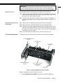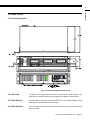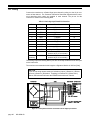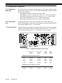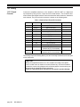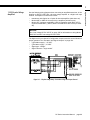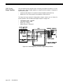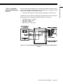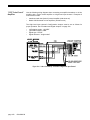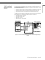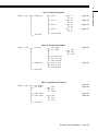
1
Sensing and Control
SC Instrumentation
Signal Conditioning,
Self-Calibrating
Digital Indicators
Model SC2001
Models SC1000 & SC2000
Model SC3004
Sensotec Sensors
Honeywell
Sensotec Sensors
2080 Arlingate Lane
Columbus, Ohio 43228, USA
Telephone: (614)850-5000
FAX: (614)850-1111
Toll Free: 1-800-848-6564
E-mail: [email protected]
http://www.honeywell.com/sensing
http://www.sensotec.com
SC Series Instruction Manual
Models SC1000, SC2000, SC2001 and SC3004
Document Number: 008-0608-00
Rev. C: February, 2005
WARNING
The operator of this instrument is advised that if the equipment is used in a manner not specified in this manual, the protection provided by the equipment may
be impaired.
CAUTION
Only qualified, service-trained personnel who are aware of the hazards involved should
remove the cover from the instrument or connect external wiring to the instrument.
WARNING
PERSONAL INJURY
DO NOT USE these products as safety or emergency stop devices, or in any other
application where failure of the product could result in personal injury.
Failure to comply with these instructions could result in death or serious injury.
Contents
Chapter 1
Introduction . . . . . . . . . . . . . . . . . . . . . . . . . . . . . . . .
1.1 About This Manual . . . . . . . . . . . . . . . . . . . . . . .
1.1.1 Scope . . . . . . . . . . . . . . . . . . . . . . . . . . . . . . . . . . . . . .
1.1.2 Conventions . . . . . . . . . . . . . . . . . . . . . . . . . . . . . . . . .
1.1.3 Organization . . . . . . . . . . . . . . . . . . . . . . . . . . . . . . . .
1.2 Related Documents . . . . . . . . . . . . . . . . . . . . . .
1.3 What is the SC Series? . . . . . . . . . . . . . . . . . . . .
1.3.1 Features . . . . . . . . . . . . . . . . . . . . . . . . . . . . . . . . . . . .
1.3.2 Chassis Models . . . . . . . . . . . . . . . . . . . . . . . . . . . . . .
1.3.3 Channel Types . . . . . . . . . . . . . . . . . . . . . . . . . . . . . . .
1.4 What is Signature Calibration? . . . . . . . . . . . . . .
1.4.1 Overview . . . . . . . . . . . . . . . . . . . . . . . . . . . . . . . . . . .
1.4.2 Benefits . . . . . . . . . . . . . . . . . . . . . . . . . . . . . . . . . . . .
1.4.3 Information Stored . . . . . . . . . . . . . . . . . . . . . . . . . . . .
3
9
9
9
9
9
11
12
12
12
12
14
14
14
14
Chapter 2
Getting Started Quickly . . . . . . . . . . . . . . . . . . . . . .
15
2.1 Locate Required Parts and Information . . . . . . .
15
2.2 Connect the Transducer to the Correct Channel of the Instrument . . . . . . . . . . . . . . . . . . . . . . . . . . . . . . . . . . . . .
15
2.3 Turn on the Instrument . . . . . . . . . . . . . . . . . . . .
16
2.4 Use the SETUP Menus to Enter Transducer Information
17
2.5 Calibrate the Transducers to Their Channels . . .
17
2.6 The SC Series Instrument is Ready for Use . . . .
17
Chapter 3
Operating Modes . . . . . . . . . . . . . . . . . . . . . . . . . . . .
3.1 Operating Modes . . . . . . . . . . . . . . . . . . . . . . . .
3.2 INITIALIZE Mode . . . . . . . . . . . . . . . . . . . . . . . .
3.3 RUN Mode . . . . . . . . . . . . . . . . . . . . . . . . . . . . .
3.5.1 Available Menus . . . . . . . . . . . . . . . . . . . . . . . . . . . . .
3.5.2 Entering and Exiting the SETUP Menu mode . . . . . . .
3.5.3 Moving Through SETUP Menus and Menu Items . . . .
3.5.4 Exiting the SETUP Menu mode . . . . . . . . . . . . . . . . . .
19
19
19
20
20
20
20
21
21
21
22
23
23
23
23
23
Chapter 4
Chassis Models . . . . . . . . . . . . . . . . . . . . . . . . . . . . .
4.1 Introduction . . . . . . . . . . . . . . . . . . . . . . . . . . . . .
25
25
3.3.1 Display . . . . . . . . . . . . . . . . . . . . . . . . . . . . . . . . . . . . .
3.3.2 [VALUE] button . . . . . . . . . . . . . . . . . . . . . . . . . . . . . .
3.3.3 [CLEAR] Button . . . . . . . . . . . . . . . . . . . . . . . . . . . . . .
3.3.4 [CHANNEL] button . . . . . . . . . . . . . . . . . . . . . . . . . . . .
3.3.5 [TARE] button . . . . . . . . . . . . . . . . . . . . . . . . . . . . . . .
3.3.6 Indicator Lights . . . . . . . . . . . . . . . . . . . . . . . . . . . . . .
3.4 ERROR mode . . . . . . . . . . . . . . . . . . . . . . . . . . .
3.5 SETUP Menu mode . . . . . . . . . . . . . . . . . . . . . .
SC Series Instruction Manual
page 3
Contents
Contents . . . . . . . . . . . . . . . . . . . . . . . . . . . . . . . . . .
4.2 Specifications . . . . . . . . . . . . . . . . . . . . . . . . . . .
4.3 Models SC1000 and SC2000 . . . . . . . . . . . . . . .
4.3.1 Differences . . . . . . . . . . . . . . . . . . . . . . . . . . . . . . . . . .
4.3.2 External Arrangement . . . . . . . . . . . . . . . . . . . . . . . . .
4.3.3 Rear Panel . . . . . . . . . . . . . . . . . . . . . . . . . . . . . . . . . .
4.3.4 Panel Mounting . . . . . . . . . . . . . . . . . . . . . . . . . . . . . .
4.3.5 Rack Mounting . . . . . . . . . . . . . . . . . . . . . . . . . . . . . . .
4.3.6 Bench Mounting . . . . . . . . . . . . . . . . . . . . . . . . . . . . . .
4.3.7 Case Removal . . . . . . . . . . . . . . . . . . . . . . . . . . . . . . .
4.3.8 Internal Arrangement . . . . . . . . . . . . . . . . . . . . . . . . . .
4.3.9 Cleaning . . . . . . . . . . . . . . . . . . . . . . . . . . . . . . . . . . . .
4.3.10 Vehicle Power Option . . . . . . . . . . . . . . . . . . . . . . . . .
4.3.11 Fuse Replacement . . . . . . . . . . . . . . . . . . . . . . . . . . .
4.4 Model SC2001 . . . . . . . . . . . . . . . . . . . . . . . . . .
4.4.1 Differences . . . . . . . . . . . . . . . . . . . . . . . . . . . . . . . . . .
4.4.2 External Arrangement . . . . . . . . . . . . . . . . . . . . . . . . .
4.4.3 Front Panel . . . . . . . . . . . . . . . . . . . . . . . . . . . . . . . . . .
4.4.4 Case Removal . . . . . . . . . . . . . . . . . . . . . . . . . . . . . . .
4.4.5 Internal Arrangement . . . . . . . . . . . . . . . . . . . . . . . . . .
4.4.6 Cleaning . . . . . . . . . . . . . . . . . . . . . . . . . . . . . . . . . . . .
4.4.7 Vehicle Power Option . . . . . . . . . . . . . . . . . . . . . . . . . .
4.4.8 Fuse Replacement . . . . . . . . . . . . . . . . . . . . . . . . . . . .
4.5 Model SC3004 . . . . . . . . . . . . . . . . . . . . . . . . . .
4.5.1 External Arrangement . . . . . . . . . . . . . . . . . . . . . . . . .
4.5.2 Rear Panel . . . . . . . . . . . . . . . . . . . . . . . . . . . . . . . . . .
4.5.3 Panel Mounting . . . . . . . . . . . . . . . . . . . . . . . . . . . . . .
4.5.4 Bench Mounting . . . . . . . . . . . . . . . . . . . . . . . . . . . . . .
4.5.5 Case Removal . . . . . . . . . . . . . . . . . . . . . . . . . . . . . . .
4.5.6 Rear Panel . . . . . . . . . . . . . . . . . . . . . . . . . . . . . . . . . .
4.5.7 Internal Arrangement . . . . . . . . . . . . . . . . . . . . . . . . . .
4.5.8 Cleaning . . . . . . . . . . . . . . . . . . . . . . . . . . . . . . . . . . . .
4.5.9 Fuse Replacement . . . . . . . . . . . . . . . . . . . . . . . . . . . .
Chapter 5
System Connector . . . . . . . . . . . . . . . . . . . . . . . . . .
5.1 Introduction . . . . . . . . . . . . . . . . . . . . . . . . . . . . .
5.2 System Connector Pinout . . . . . . . . . . . . . . . . .
5.3 Function Input Pins . . . . . . . . . . . . . . . . . . . . . . .
5.3.1 Overview . . . . . . . . . . . . . . . . . . . . . . . . . . . . . . . . . . .
5.3.2 Example . . . . . . . . . . . . . . . . . . . . . . . . . . . . . . . . . . . .
5.4 Limit Output Pins . . . . . . . . . . . . . . . . . . . . . . . .
5.4.1 Overview . . . . . . . . . . . . . . . . . . . . . . . . . . . . . . . . . . .
5.4.2 Example . . . . . . . . . . . . . . . . . . . . . . . . . . . . . . . . . . . .
Chapter 6
System Menu . . . . . . . . . . . . . . . . . . . . . . . . . . . . . .
6.1 Overview . . . . . . . . . . . . . . . . . . . . . . . . . . . . . .
6.2 Menu Items . . . . . . . . . . . . . . . . . . . . . . . . . . . . .
6.2.1 SOFTWARE REVISION Menu Item . . . . . . . . . . . . . . . . . .
6.2.2 CONFIGURATION Sub-Menu . . . . . . . . . . . . . . . . . . . . . .
6.2.3 DIAGNOSTICS Sub-Menu . . . . . . . . . . . . . . . . . . . . . . . .
6.2.4 INSTALL CHANNEL Menu Item . . . . . . . . . . . . . . . . . . . .
6.2.5 DELETE CHANNEL Menu Item . . . . . . . . . . . . . . . . . . . . .
6.2.6 DEFAULT CHANNEL Menu Item . . . . . . . . . . . . . . . . . . . .
page 4
008-0608-00
26
27
27
27
27
27
28
28
28
29
30
30
30
31
31
31
31
31
32
32
32
32
33
33
33
33
33
34
34
34
34
34
35
35
36
37
37
37
38
38
38
41
41
41
41
41
41
42
44
44
7.3.1 RS-232 vs. RS-485 . . . . . . . . . . . . . . . . . . . . . . . . . . .
7.3.2 Parameters . . . . . . . . . . . . . . . . . . . . . . . . . . . . . . . . .
7.4 Serial Com Menu . . . . . . . . . . . . . . . . . . . . . . . .
7.4.1 Overview . . . . . . . . . . . . . . . . . . . . . . . . . . . . . . . . . . .
7.4.2 INTERFACE Menu Item . . . . . . . . . . . . . . . . . . . . . . . . .
7.4.3 ADDRESS Menu Item . . . . . . . . . . . . . . . . . . . . . . . . . . .
7.4.4 BAUD RATE Menu Item . . . . . . . . . . . . . . . . . . . . . . . . .
7.4.5 AUTO LINE-FEED Menu Item . . . . . . . . . . . . . . . . . . . .
7.4.6 TRANSMIT TEST Menu Item . . . . . . . . . . . . . . . . . . . . .
7.4.7 LEAVE MENU Menu Item . . . . . . . . . . . . . . . . . . . . . . . .
Chapter 8
Display Menu . . . . . . . . . . . . . . . . . . . . . . . . . . . . . . .
8.1 Overview . . . . . . . . . . . . . . . . . . . . . . . . . . . . . . .
8.2 Menu Items for Models SC1000, SC2000, SC2001
8.2.1 UPPER CHANNEL Menu Item . . . . . . . . . . . . . . . . . . . . .
8.2.2 LOWER CHANNEL Menu Item . . . . . . . . . . . . . . . . . . . .
8.2.3 LOWER MODE Menu Item . . . . . . . . . . . . . . . . . . . . . . . .
8.2.4 DISPLAY DISABLE Menu Item . . . . . . . . . . . . . . . . . . .
8.3 Menu Items for Model SC3004 . . . . . . . . . . . . . .
8.3.1 POWER-ON CHANNEL Menu Item . . . . . . . . . . . . . . . . . .
Chapter 9
Limits . . . . . . . . . . . . . . . . . . . . . . . . . . . . . . . . . . . . .
9.1 Understanding Limits, Set Points and Return Points
9.2 Limit Operation . . . . . . . . . . . . . . . . . . . . . . . . . .
9.2.1 Actions When Activated . . . . . . . . . . . . . . . . . . . . . . . .
9.2.2 Scan Time . . . . . . . . . . . . . . . . . . . . . . . . . . . . . . . . . .
9.3 Limit Menus . . . . . . . . . . . . . . . . . . . . . . . . . . . . .
9.3.1 Overview . . . . . . . . . . . . . . . . . . . . . . . . . . . . . . . . . . .
9.3.2 LIMIT.ENABLE Menu Item . . . . . . . . . . . . . . . . . . . . . .
9.3.3 LIMIT.SETPOINT Menu Item . . . . . . . . . . . . . . . . . . . .
9.3.4 LIMIT.RETURN PNT Menu Item . . . . . . . . . . . . . . . . . . .
9.3.5 LIMIT.ENERGIZE Menu Item . . . . . . . . . . . . . . . . . . . .
9.3.6 LIMIT.LATCHING Menu Item . . . . . . . . . . . . . . . . . . . .
9.3.7 LIMIT.CHANNEL Menu Item . . . . . . . . . . . . . . . . . . . . .
9.3.8 LIMIT.SOURCE Menu Item . . . . . . . . . . . . . . . . . . . . . .
9.3.9 LEAVE MENU Menu Item . . . . . . . . . . . . . . . . . . . . . . . .
Chapter 10
Strain-Gage Input Channel . . . . . . . . . . . . . . . . . . . .
10.1 Features . . . . . . . . . . . . . . . . . . . . . . . . . . . . . .
10.2 Wiring . . . . . . . . . . . . . . . . . . . . . . . . . . . . . . . .
10.3 Calibration Procedure . . . . . . . . . . . . . . . . . . . .
10.4 Specifications . . . . . . . . . . . . . . . . . . . . . . . . . .
10.5 Channel Menu . . . . . . . . . . . . . . . . . . . . . . . . . .
10.5.1 OPERATION Sub-Menu . . . . . . . . . . . . . . . . . . . . . . . .
SC Series Instruction Manual
47
47
47
48
48
48
49
49
49
49
49
49
49
49
51
51
51
51
51
51
51
51
51
53
53
54
54
54
55
55
55
55
55
55
57
57
57
57
59
59
60
61
62
63
63
page 5
Contents
Chapter 7
Serial Communications . . . . . . . . . . . . . . . . . . . . . .
7.1 Overview . . . . . . . . . . . . . . . . . . . . . . . . . . . . . . .
7.2 Wiring . . . . . . . . . . . . . . . . . . . . . . . . . . . . . . . . .
7.3 Communications Protocol . . . . . . . . . . . . . . . . . .
10.5.2 DISPLAY SETUP Sub-Menu . . . . . . . . . . . . . . . . . . . . .
10.5.3 AUXn FUNCTION Menu Items . . . . . . . . . . . . . . . . . . . .
10.5.4 CALIBRATION TYPE Menu Item . . . . . . . . . . . . . . . . . .
10.5.5 CALIBRATION DATA Sub-Menu . . . . . . . . . . . . . . . . . .
10.5.6 CALIBRATE Menu Item . . . . . . . . . . . . . . . . . . . . . . . .
10.5.7 DAC SETUP Sub-Menu . . . . . . . . . . . . . . . . . . . . . . . . .
10.5.8 SIGNATURE MODULE Sub-Menu . . . . . . . . . . . . . . . . . .
10.5.9 DIAGNOSTICS Sub-Menu . . . . . . . . . . . . . . . . . . . . . . .
10.6 Analog Output Configuration . . . . . . . . . . . . . .
10.6.1 Identifying the Output Type . . . . . . . . . . . . . . . . . . . .
10.6.2 Channel Menu Items . . . . . . . . . . . . . . . . . . . . . . . . .
10.6.3 Output Selection . . . . . . . . . . . . . . . . . . . . . . . . . . . . .
10.7 Troubleshooting . . . . . . . . . . . . . . . . . . . . . . . .
10.7.1 Error Messages . . . . . . . . . . . . . . . . . . . . . . . . . . . . .
10.7.2 Common Problems and Solutions . . . . . . . . . . . . . . .
Chapter 11
AC/AC-LVDT Input Channel . . . . . . . . . . . . . . . . . . .
11.1 Features . . . . . . . . . . . . . . . . . . . . . . . . . . . . . .
11.2 Wiring . . . . . . . . . . . . . . . . . . . . . . . . . . . . . . . .
11.3 Calibration Procedure . . . . . . . . . . . . . . . . . . . .
11.4 Specifications . . . . . . . . . . . . . . . . . . . . . . . . . .
11.5 Channel Menu . . . . . . . . . . . . . . . . . . . . . . . . .
11.5.1 OPERATION Sub-Menu . . . . . . . . . . . . . . . . . . . . . . . . .
11.5.2 DISPLAY SETUP Sub-Menu . . . . . . . . . . . . . . . . . . . . .
11.5.3 AUXn FUNCTION Menu Items . . . . . . . . . . . . . . . . . . . .
11.5.4 CALIBRATION TYPE Menu Item . . . . . . . . . . . . . . . . . .
11.5.5 CALIBRATION DATA Sub-Menu . . . . . . . . . . . . . . . . . .
11.5.6 CALIBRATE Menu Item . . . . . . . . . . . . . . . . . . . . . . . .
11.5.7 DAC SETUP Sub-Menu . . . . . . . . . . . . . . . . . . . . . . . . .
11.5.8 DIAGNOSTICS Sub-Menu . . . . . . . . . . . . . . . . . . . . . . .
11.6 Electrical Null and Transducer Mounting . . . . .
11.6.1 Overview . . . . . . . . . . . . . . . . . . . . . . . . . . . . . . . . . .
11.6.2 Procedure . . . . . . . . . . . . . . . . . . . . . . . . . . . . . . . . . .
11.7 Analog Output Configuration . . . . . . . . . . . . . .
11.7.1 Identifying the Output Type . . . . . . . . . . . . . . . . . . . .
11.7.2 Channel Menu Items . . . . . . . . . . . . . . . . . . . . . . . . .
11.7.3 Output Selection . . . . . . . . . . . . . . . . . . . . . . . . . . . . .
11.8 Troubleshooting . . . . . . . . . . . . . . . . . . . . . . . .
11.8.1 Error Messages . . . . . . . . . . . . . . . . . . . . . . . . . . . . .
11.8.2 Common Problems and Solutions . . . . . . . . . . . . . . .
Chapter 12
High-Level Input Channel . . . . . . . . . . . . . . . . . . . .
12.1 Features . . . . . . . . . . . . . . . . . . . . . . . . . . . . . .
12.2 Wiring . . . . . . . . . . . . . . . . . . . . . . . . . . . . . . . .
12.2.1 Channel Connector . . . . . . . . . . . . . . . . . . . . . . . . . .
12.2.2 Bi-polar Voltage Amplifiers . . . . . . . . . . . . . . . . . . . . .
12.2.3 “3-wire Voltage” Amplifiers . . . . . . . . . . . . . . . . . . . . .
12.2.4 “3-wire Voltage” Amplifiers with Single-wire Shunt Cal
12.2.5 “3-wire Current” Amplifiers . . . . . . . . . . . . . . . . . . . .
12.2.6 “2-wire Current” Amplifiers with Buffered Shunt Cal .
12.2.7 “2-wire Current” Amplifiers with Single-wire Shunt Cal
12.2.8 Low Voltage DC-DC LVDTs . . . . . . . . . . . . . . . . . . . .
page 6
008-0608-00
65
66
67
69
71
73
74
75
76
76
76
76
77
77
77
79
79
80
81
82
83
83
85
85
87
88
89
91
92
93
93
93
94
94
94
94
95
95
95
97
97
98
98
99
100
101
102
103
104
105
12.3 Excitation and Signal Jumpers . . . . . . . . . . . . .
12.4 Calibration Procedure . . . . . . . . . . . . . . . . . . . .
12.5 Specifications . . . . . . . . . . . . . . . . . . . . . . . . . .
12.6 Channel Menu . . . . . . . . . . . . . . . . . . . . . . . . . .
12.6.1 OPERATION Sub-Menu . . . . . . . . . . . . . . . . . . . . . . . .
12.6.2 DISPLAY SETUP Sub-Menu . . . . . . . . . . . . . . . . . . . . .
12.6.3 AUXn FUNCTION Menu Items . . . . . . . . . . . . . . . . . . .
12.6.4 CALIBRATION TYPE Menu Item . . . . . . . . . . . . . . . . . .
12.6.5 CALIBRATION DATA Sub-Menu . . . . . . . . . . . . . . . . . .
12.6.6 CALIBRATE Menu Item . . . . . . . . . . . . . . . . . . . . . . . .
12.6.7 DAC SETUP Sub-Menu . . . . . . . . . . . . . . . . . . . . . . . .
12.6.8 DIAGNOSTICS Sub-Menu . . . . . . . . . . . . . . . . . . . . . .
12.7 Analog Output Configuration . . . . . . . . . . . . . . .
12.7.1 Identifying the Output Type . . . . . . . . . . . . . . . . . . . .
12.7.2 Channel Menu Items . . . . . . . . . . . . . . . . . . . . . . . . .
12.7.3 Output Selection . . . . . . . . . . . . . . . . . . . . . . . . . . . .
12.8 Troubleshooting . . . . . . . . . . . . . . . . . . . . . . . .
12.8.1 Error Messages . . . . . . . . . . . . . . . . . . . . . . . . . . . . .
12.8.2 Common Problems and Solutions . . . . . . . . . . . . . . .
Chapter 13
Relay Output Channel . . . . . . . . . . . . . . . . . . . . . . . .
13.1 Features . . . . . . . . . . . . . . . . . . . . . . . . . . . . . .
13.1.1 First Channel Installed . . . . . . . . . . . . . . . . . . . . . . . .
13.1.2 Second Channel Installed . . . . . . . . . . . . . . . . . . . . .
13.1.3 Third Channel Installed . . . . . . . . . . . . . . . . . . . . . . .
13.1.4 Fourth Channel Installed . . . . . . . . . . . . . . . . . . . . . .
13.2 Wiring . . . . . . . . . . . . . . . . . . . . . . . . . . . . . . . .
13.3 Setup Procedure . . . . . . . . . . . . . . . . . . . . . . . .
13.4 Specifications . . . . . . . . . . . . . . . . . . . . . . . . . .
13.5 Channel Menu . . . . . . . . . . . . . . . . . . . . . . . . . .
13.5.1 DIAGNOSTICS Sub-Menu . . . . . . . . . . . . . . . . . . . . . .
Chapter 14
DAC Output Channel . . . . . . . . . . . . . . . . . . . . . . . .
14.1 Features . . . . . . . . . . . . . . . . . . . . . . . . . . . . . .
14.2 Wiring . . . . . . . . . . . . . . . . . . . . . . . . . . . . . . . .
14.3 Setup Procedure . . . . . . . . . . . . . . . . . . . . . . . .
14.4 Specifications . . . . . . . . . . . . . . . . . . . . . . . . . .
14.5 Channel Menu . . . . . . . . . . . . . . . . . . . . . . . . . .
14.5.1 DAC SETUP Sub-Menu . . . . . . . . . . . . . . . . . . . . . . . .
14.5.2 DIAGNOSTICS Sub-Menu . . . . . . . . . . . . . . . . . . . . . .
14.6 Analog Output Configuration . . . . . . . . . . . . . . .
14.6.1 Identifying the Output Type . . . . . . . . . . . . . . . . . . . .
14.6.2 Channel Menu Items . . . . . . . . . . . . . . . . . . . . . . . . .
14.6.3 Output Selection . . . . . . . . . . . . . . . . . . . . . . . . . . . .
14.7 Troubleshooting . . . . . . . . . . . . . . . . . . . . . . . .
14.7.1 Error Messages . . . . . . . . . . . . . . . . . . . . . . . . . . . . .
14.7.2 Common Problems and Solutions . . . . . . . . . . . . . . .
SC Series Instruction Manual
106
106
106
107
108
109
109
111
112
113
115
117
119
120
121
121
121
121
122
122
122
123
123
123
123
123
123
124
125
126
127
127
129
129
130
131
132
133
133
134
135
135
135
135
136
136
136
page 7
Contents
12.3.1 Overview . . . . . . . . . . . . . . . . . . . . . . . . . . . . . . . . . .
12.3.2 Setting Jumpers . . . . . . . . . . . . . . . . . . . . . . . . . . . . .
Chapter 15
Split Display Virtual Channel . . . . . . . . . . . . . . . . . .
15.1 Features . . . . . . . . . . . . . . . . . . . . . . . . . . . . . .
15.2 Wiring . . . . . . . . . . . . . . . . . . . . . . . . . . . . . . . .
15.3 Setup Procedure . . . . . . . . . . . . . . . . . . . . . . .
15.4 Channel Menu . . . . . . . . . . . . . . . . . . . . . . . . .
15.5 Troubleshooting . . . . . . . . . . . . . . . . . . . . . . . .
Chapter 16
Mathematics Virtual Channel . . . . . . . . . . . . . . . . .
16.1 Features . . . . . . . . . . . . . . . . . . . . . . . . . . . . . .
16.2 Wiring . . . . . . . . . . . . . . . . . . . . . . . . . . . . . . . .
16.3 Setup Procedure . . . . . . . . . . . . . . . . . . . . . . .
16.4 Channel Menu . . . . . . . . . . . . . . . . . . . . . . . . .
16.5 Troubleshooting . . . . . . . . . . . . . . . . . . . . . . . .
143
143
144
145
146
146
146
146
146
147
148
149
Chapter 17
Error Messages . . . . . . . . . . . . . . . . . . . . . . . . . . . . .
17.1 Overview . . . . . . . . . . . . . . . . . . . . . . . . . . . . .
17.2 Error Message List . . . . . . . . . . . . . . . . . . . . . .
151
151
152
Chapter 18
Setup Menu Reference . . . . . . . . . . . . . . . . . . . . . . .
18.1 Navigation instructions . . . . . . . . . . . . . . . . . . .
157
157
Index . . . . . . . . . . . . . . . . . . . . . . . . . . . . . . . . . . . .
169
Warranty . . . . . . . . . . . . . . . . . . . . . . . . . . . . . . . . .
173
16.4.1 SENSOCODE P/N Menu Item . . . . . . . . . . . . . . . . . . . .
16.4.2 USER VALUES Sub-Menu . . . . . . . . . . . . . . . . . . . . . . .
16.4.3 VIEW SENSOCODE Menu Item . . . . . . . . . . . . . . . . . . .
16.4.4 VIEW COMMANDS Sub-Menu . . . . . . . . . . . . . . . . . . . .
16.4.5 DISPLAY SETUP Sub-Menu . . . . . . . . . . . . . . . . . . . . .
16.4.6 POWER-ON SOURCE Menu Item . . . . . . . . . . . . . . . . . . .
page 8
008-0608-00
139
139
139
139
140
140
1.1.1 Scope
This manual will explain the setup, features and operation of 3rd generation SC
Series instruments, specifically the models SC1000, SC2000, SC2001 and
SC3004.
Further information about customer specific programming and setup will be
explained on the Customer Information Sheet that is provided with every instrument.
1.1.2 Conventions
1.1.3 Organization
This manual uses the following conventions to present information:
[TEXT IN BRACKETS]
The label of a front panel button.
DISPLAY
Text that appears on the display, such as error
messages or menu items.
->
Indicates that what follows is an item from a
sub-menu, such as SYSTEM MENU -> DIAGNOSTICS.
Chapter 1, “Introduction”, offers general information about the SC Series and
this instruction manual.
Chapter 2, “Getting Started Quickly”, provides an overview of how to get
started quickly if your instrument and transducers were ordered at the same time,
or if Signature Calibration is used.
Chapter 3, “Operating Modes”, discusses the significant features of the SC
Series and operation procedures when the instrument is in the INITIALIZE, RUN,
ERROR or SETUP modes.
Chapter 4, “Chassis Models”, explains the differences between the SC1000,
SC2000, SC2001 and SC3004 chassis. Information relating to the hardware
chassis such as panel and rack mounting is given.
Chapter 5, “System Connector”, contains information about wiring to the 25-pin
System connector to access the Limit Outputs, Function Inputs and serial communications.
Chapter 6, “System Menu”, discusses the System Menu which allows you to
examine and change settings that affect the operation of the chassis.
Chapter 7, “Serial Communications”, briefly describes RS-232 and RS-485
communications. It also shows how to use the SERIAL COM Menu to examine the
settings and test the RS-232 or RS-485 communications.
Chapter 8, “Display Menu”, describes the Display Menu which allows you to
change what is displayed on the lower line of the SC2000 and SC2001 instruments.
Chapter 9, “Limits”, discusses how the limits operate and describes how to alter
their settings via the Limit Menus.
Chapter 10, “Strain-Gage Input Channel”, explains how to wire, configure,
SC Series Instruction Manual
page 9
Introduction
1.1 About This Manual
1
Chapter 1
Introduction
operate and calibrate Strain-Gage Input Channels with your transducers.
Chapter 11, “AC/AC-LVDT Input Channel”, explains how to wire, configure, operate
and calibrate AC/AC-LVDT Input Channels with your transducers.
Chapter 12, “High-Level Input Channel”, explains how to wire, configure, operate
and calibrate High-Level Input Channels with your amplified transducers, in-line amplifiers, or DC-DC LVDTs.
Chapter 13, “Relay Output Channel”, describes how a Relay Output channel can
enable additional limits in the instrument.
Chapter 14, “DAC Output Channel”, explains the configuration and operation of
additional digital-to-analog voltage or current outputs.
Chapter 15, “Split Display Virtual Channel”, shows how you can display two values
from any of the channels in the instrument at the same time.
Chapter 16, “Mathematics Virtual Channel”, describes the flexibility of customerspecific SensoCode programming.
Chapter 17, “Error Messages”, lists error messages that the instrument may display,
describes their causes and, where possible, suggests solutions.
Chapter 18, “Setup Menu Reference”, is a list of all SETUP menus and a cross-reference to related information in this instruction manual.
page 10
008-0608-00
1
1.2 Related Documents
Every instrument is shipped with a Customer Information Sheet which documents
important information specific to each instrument, such as:
•
•
•
•
Communications Guide
part number,
date of manufacture,
list of all installed channels and their setup information,
customer specific SensoCode programming of Mathematics Virtual channels
and operation notes.
The “SC Series Communications Guide”, document 008-0610-00, describes in
detail how to communicate with an SC Series instrument using RS-232 and RS485. Wiring diagrams, sample programs, and descriptions of each command are
included.
A printed copy of this document is available for order, or you may download it from
http://www.honeywell.com/sensotec.
Supplemental Instructions
If an instrument is configured with Mathematics Virtual channels, one or more sets
of Supplemental Instructions may be included. These instructions contain important information about which indicator lights, Function Input pins and/or Limit Output pins of the System connector are used by the Mathematics Virtual channel.
SC Series Instruction Manual
page 11
Introduction
Customer Information Sheet
1.3 What is the SC Series?
The SC Series of Signal Conditioners/Indicators are versatile, multi-channel devices
designed to operate with many different types of sensors. Several different chassis
types, Input channels, and Output channels are available to allow the configuration of
an SC instrument to meet a variety of measurement and control needs. The operation
of an SC instrument is based on digital technology to provide improved accuracy,
superior ease of setup, and a wealth of features.
1.3.1 Features
The main features of the models SC1000, SC2000, SC2001 and SC3004 are:
•
•
•
•
•
•
•
•
1.3.2 Chassis Models
Four alarm limits (optional sixteen), with versatile setup (not available on Model
SC1000)
Automatic setup, calibration, and scaling of strain-gage sensors through the use
of Signature CalibrationTM
Field selectable, digital, low-pass filtering (“damping”) on each Input channel
Up to ±50,000 part resolution
Field selectable five-, six - or seven-digit (9,999,999 maximum) display
RS-232 communications standard (RS-485 optional)
Local or remote setup using the RS-232 or RS-485 port
Push-button on/off tare feature
Several models (i.e. chassis types) are available:
•
•
•
•
SC1000: 1 to 4 physical channels, 3/8 DIN case, no limits or peak detector
SC2000: 1 to 4 physical channels, 3/8 DIN case
SC2001: 1 to 4 physical channels, portable case
SC3004: 1 to 14 physical channels, 19” rack mount case, 1 to 3 quad-line displays
1.3.3 Channel Types
Channels can be one of three types: Input, Output, or Virtual
Input Channels
Input channels are hardware circuit boards with a unique channel number. Currently,
they are available for the following types of sensors:
•
•
•
•
•
Output Channels
Output channels are hardware circuit boards with a unique channel number. They
include:
•
•
Virtual Channels
008-0608-00
Relay Output channels, which can add additional limits to the standard four (N/A
on Model SC1000).
DAC Output channels, which provide additional voltage or current outputs.
Virtual channels are software based devices that occupy a channel number, but not a
physical slot, in an instrument.
•
page 12
Strain-gage sensors, such as unamplified pressure transducers and load cells
Sensors with voltage outputs, such as transducers with the Option 2a, 2b, 2c, 2d,
2g, 2j, 2k, 2p, 2t or 2y internal amplifier
Sensors with current outputs, such as transducers with the Option 2j, 2k or 2n
internal amplifier
AC-AC LVDTs (Linear Variable Displacement Transducers)
DC-DC LVDTs
Split Display Virtual channels allow the displaying of any two channel’s track, peak
or valley values at the same time.
SC Series Instruction Manual
page 13
Introduction
Mathematics Virtual channels run small programs written in an interpretive
language called SensoCode. This provides great flexibility which allows the
SC Series to do many jobs which otherwise requires a personal computer or
PLC.
1
•
1.4 What is Signature Calibration?
1.4.1 Overview
A small integrated circuit is located either inside the transducer, in an in-line package
between the instrument and the transducer, or in the connector of a cable. All data
necessary to set up the transducer with the instrument are stored (even linearity data),
and setup is automatic when a new transducer is connected to the instrument.
The Strain-Gage Input channel of the SC Series is designed to operate with Signature
Calibration. It will automatically set itself up with transducers which contain the memory device, but can also be set up using a front-panel interactive procedure. The Signature Calibration module can also be programmed from the instrument’s front panel.
Signature Calibration is only available with unamplified strain-gage transducers.
1.4.2 Benefits
The benefits are:
•
•
•
•
•
1.4.3 Information
Stored
The following information is stored inside transducers equipped with Signature Calibration:
•
•
•
•
•
•
•
•
page 14
008-0608-00
The transducer’s Calibration Record is always located where it is needed most...
with the transducer.
The instrument is always set up correctly with the transducer.
Interchanging of transducers and instruments is a quick process.
A User Calibration Data area that can be altered by customers to fit their requirements.
A Factory Calibration Sheet Data area, unalterable by the customer, can be copied back into the User Calibration Data.
Full-scale mV/V: The full-scale millivolt-per-volt (mV/V) rating of the transducer
when its full load is applied; also called “calibration factor”.
Shunt-Cal mV/V: The millivolt-per-volt output of the transducer when the shunt
calibration resistor is placed across its (-)SIGNAL and (-)EXCITATION leads.
Shunt Resistance: The resistance value, in Ohms, that was used to obtain the
shunt-cal mV/V value above.
Full-Scale Value: The full scale value of the transducer, in engineering units.
Engineering Units: The engineering units that the transducer is calibrated in (i.e.
pounds, grams, pascals, inches of water, etc.).
Serial Number: The serial number of the transducer.
Excitation Voltage: The magnitude and type of signal used to excite the transducer.
Linearization Points (optional): These can be used by an instrument using Shunt
Calibration or Millivolt-per-Volt Calibration to correct any non-linearity in the transducer and thus improve the accuracy of the system. An additional “multiple-point
calibration” can be purchased with the transducer that allows linearity correction
information to be placed into its Signature Calibration module.
The following items are required to set up an SC Series instrument with your
transducer:
•
•
•
•
•
•
SC Series instrument
Transducers that are to be connected to the instrument
For each transducer to be connected to the instrument, a connecting cable.
This cable will have a 12-pin, green, plastic connector on one end and the
transducer’s mating connector on the other end. Usually, this cable is ordered
along with the instrument and transducer.
If the connecting cable was not ordered with the instrument, you may need to
make this cable.
The transducer’s Calibration Record or Certificate of Calibration.
The Customer Information Sheet that shipped with your instrument. This
sheet describes which cards are installed in each channel.
Power cord for the instrument.
2.2 Connect the Transducer to the Correct Channel of the Instrument
For each transducer, attach its connecting cable to the transducer, and then to the
correct 12-pin channel-connector on the instrument.
The Customer Information Sheet indicates which serial numbered transducer is to
be connected to each channel of the instrument.
If the instrument and transducer(s) were not purchased with a connecting cable,
you may need to make this cable. For the transducer’s pin connections, see that
transducer’s calibration record. For the pin connections for that channel of the
instrument, see the appropriate chapter in this manual. For example, if you wish
to wire to a Strain-Gage Input Channel see the chapter “Strain-Gage Input Channel” on page 59.
SC Series Instruction Manual
page 15
Getting Started Quickly
2.1 Locate Required Parts and Information
2
Chapter 2
Getting Started Quickly
2.3 Turn on the Instrument
Connect the power cord between the instrument power source and the instrument,
and turn the On/Off switch on the back of the instrument to the On position.
The instrument enters its INITIALIZE mode that lasts a few seconds per channel. As
each channel in the instrument is initialized, the transducer's serial number may be
seen on the display if the transducer has a Signature Calibration Module in it.
NOTICE
If the channel’s display flashes “APPLY 00000.” (or some other load value), the
instrument has detected a transducer other than the one which was last calibrated with that channel. The instrument is prompting you to apply the
requested load to the transducer so that a “mV/V Calibration” or a “Shunt Calibration” can take place.
After making certain that the correct transducer is connected this channel,
press the [ENTER] button after you have applied the requested load to perform
the calibration.
NOTICE
If the instrument displays error code 57 or 68, it has detected a transducer
other than the one which was last calibrated with that channel. Furthermore,
the channel cannot perform an automatic calibration because its calibration
type has been set to “Known Load Calibration”.
Either re-connect the correct transducer to the channel, or see “CALIBRATION
TYPE Menu Item” on page 67 to select another calibration type.
When the instrument enters its normal operating mode (RUN mode), you will see the
following format on the front panel display:
1•
00000. PSIG "
where:
•
•
•
•
•
page 16
008-0608-00
Channel number: “1” is the channel number.
Value type: The next character indicates the nature of the following value.
A blank character indicates the tracking value. The instrument is “tracking” the signal, continuously updating the display in response to the signal from the transducer.
A “•" character indicates the peak value (highest value seen since the [CLEAR]
button was last pressed).
A “–" character indicates the valley value (lowest value seen since the [CLEAR]
button was last pressed).
Data value: “00000.” displays the value from the transducer in engineering units.
Units label: “PSIG” indicates the engineering units being used (up to 4 characters).
Tare indicator: A “"“ symbol indicates tare is off; a “Ë“ symbol indicates tare is on.
2
2.4 Use the SETUP Menus to Enter Transducer Information
•
•
You are using a transducer equipped with Signature Calibration, or
The transducer and instrument were purchased together and set up by Sensotec.
Otherwise, you must enter information about your transducer into the SETUP
menu of the channel to which it is connected. See the appropriate chapter of this
manual for that card type.
2.5 Calibrate the Transducers to Their Channels
You can skip this step if:
•
•
You are using a transducer equipped with Signature Calibration, or
The transducer and instrument were purchased together and set up by Sensotec.
Otherwise, you must choose a calibration method (e.g. Shunt Calibration, mV/V
Calibration, or Known Load Calibration) appropriate for your application and use
the SETUP menu for that channel to calibrate the channel to the transducer. See
the appropriate chapter of this manual for that card type.
2.6 The SC Series Instrument is Ready for Use
See “RUN Mode” on page 20 for information on how to operate the instrument
while it is in the RUN mode.
Apply some test stimulus on the transducer to observe changes in the display.
SC Series Instruction Manual
page 17
Getting Started Quickly
You can skip this step if:
page 18
008-0608-00
The SC Series instruments have four modes of operation:
•
•
•
INITIALIZE, to test the instrument upon power up
RUN, normal operation
ERROR, which indicates that an abnormal situation has occurred that
stopped the operation of the instrument
• SETUP, a menu which allows setup and calibration of the chassis and its
channels
Each of these will be described in this chapter.
3.2 INITIALIZE Mode
When the instrument is powered up or otherwise reset, it enters the INITIALIZE
mode. As the instrument enters this mode, all segments of the display and all
front panel indicator lights (if available) illuminate momentarily. Next, each channel
in the instrument is checked for proper operation.
If a problem is detected, the instrument may enter the ERROR mode.
Depending on the type of channel, other actions may occur. For example, a
Strain-Gage channel will calibrate its analog-to-digital converter and attempt to
read the transducer’s Signature Calibration information. If the transducer is
equipped with Signature Calibration, the transducer’s serial number is displayed
momentarily.
SC Series Instruction Manual
page 19
Operating Modes
3.1 Operating Modes
3
Chapter 3
Operating Modes
3.3 RUN Mode
After the INITIALIZE mode finishes, the instrument enters the RUN mode, its normal
mode of operation.
3.3.1 Display
Model SC3004 and upper
line of SC1000, SC2000,
SC2001
The display will show a channel number on the far left, followed by the channel’s operation messages.
For example, a Strain Gage amplifier channel will use the format below:
1•
00000. PSIG "
where:
•
•
•
•
•
Lower Line of SC1000,
SC2000, SC2001
Channel number: “1” is the channel number.
Value type: The next character indicates the nature of the following value.
A blank character indicates the display is being continuously updated by “tracking”
the input signal to the channel.
A “•" character indicates the peak value (highest value seen since the [CLEAR]
button was last pressed).
A “–" character indicates the valley value (lowest value seen since the [CLEAR]
button was last pressed).
Data value: “00000.” displays the value from the transducer in engineering units.
Units label: “PSIG” indicates the engineering units being used (up to 4 characters).
Tare indicator: A “"“ symbol indicates tare is off; a “Ë“ symbol indicates tare is on.
The contents of the display’s lower line is selected with the “DISPLAY MENU -> LOWER MODE”
menu item as either displaying a channel or indicating the status of Limits. See “Indicator Lights” on page 21.
3.3.2 [VALUE] button
NOTICE
The [VALUE] button is not used by SC1000 instruments in the RUN mode.
After the channel number, the next characters indicate which data value for the displayed channel is shown. There are three (possibly four) data values available from
each channel:
•
•
•
•
(blank), tracking data value
“•", peak data value, (highest value since the peak/valley detector was cleared)
“–", valley data value, (lowest value since the peak/valley detector was cleared)
“Û", percentage of the Analog-to-Digital converter’s full-scale digitizing capability.
This data value is only available when the channel’s “DIAGNOSTICS->DISPLAY ADC”
menu item is set to “ON”.
Pressing and releasing the [VALUE] button cycles though the available sources for
data values for the displayed channel.
3.3.3 [CLEAR] Button
Pressing and releasing the [CLEAR] button will reset the peak and valley values of the
channel being monitored by the display to the track value. Additionally, any limits in
the instrument that are “latched” will be reset.
NOTICE
The [CLEAR] button is not used by SC1000 instruments in RUN mode.
page 20
008-0608-00
3.3.4 [CHANNEL] button
If the configuration of the instrument contains more than one channel, the left
most characters of the display indicates which channel the display is monitoring.
Pressing and releasing the [CHANNEL] button will cause the next channel to be
displayed.
On instruments with a dual-line display, the [CHANNEL] button cannot be used to
change which channel the lower line is monitoring. That is selected with the “DISPLAY MENU -> LOWER CHANNEL” menu item.
Shunt Calibration Check
If the [CHANNEL] button is held down for more than 3 seconds, the present channel’s shunt calibration value (if the channel has shunt calibration available) will be
displayed.
3.3.5 [TARE] button
To reset the channel’s display to zero, press the [TARE] button while in RUN
mode. To restore the tare value, press the [TARE] button again. The “Tare” indicator will illuminate when tare is on.
To tare all channels simultaneously, use the System connector’s Function 1 Input
pin. See “System Connector” on page 35.
To tare a single channel regardless of which channel is being monitored by the
display, use the channel’s AUX1 or AUX2 control pins on its connector. See the
particular chapter regarding that channel for details.
3.3.6 Indicator Lights
Models SC1000, SC2000, SC2001
A “"“ symbol on the right side of a channel’s display indicates tare is off for that
channel; a “Ë“ symbol indicates tare is on.
If the lower line of the display is configured with the “DISPLAY MENU -> LOWER MODE”
menu item as “LIMIT 01-04”, then the lower line will monitor the status of Limits 1, 2,
3 and 4. A “"“ symbol indicates a limit is deactivated; a “Ë“ symbol indicates a limit
is activated. For example:
L1" L2" L3Ë L4Ë
indicates that Limit 1 and Limit 2 are deactivated and Limit 3 and Limit 4 are activated. Since the SC1000 is not equipped with limits, the lower line of the display
will be blank. See “LOWER MODE Menu Item” on page 51.
These indicators may be overridden by the operation of a Mathematics channel in
special applications.
Model SC3004
Front panel lights “L-1”, “L-2”, “L-3”, and “L-4”, monitor the status of Limits 1, 2, 3,
and 4. Model SC3004 instruments also include front panel lights labeled “L-5”, “L6”, “L-7” and “L-8” which monitor the status of optional Limits 5, 6, 7, and 8.
The function of the front panel lights may be overridden by the operation of a
Mathematics channel in special applications.
SC Series Instruction Manual
page 21
Operating Modes
To clear the peak and valley values of a single channel regardless of which channel is being monitored by the display, use the channel’s AUX1 or AUX2 control
pins on its connector. See the particular chapter regarding that channel for
details.
3
To clear the peak and valley values of all channels simultaneously, use the System connector’s Function Input #2 pin. See “System Connector” on page 35 for
details.
3.4 ERROR mode
The instrument enters the ERROR mode when a critical error occurs that prevents the
instrument from operating. The display alternates between displaying a two-digit code
in the form “ERROR xx ON CH.yy” and a short description of the error. The first two
digits “xx” hold the error code. The last two digits, “yy” is channel number that caused
the error. For example, “ERROR 60 ON CH.01” indicates that error number 60 occurred on
channel 1.
While the instrument is in the ERROR mode, no other operations are taking place
except for limited serial communications capabilities. See “Error Message List” on
page 152 for a list of error codes and their probable causes.
page 22
008-0608-00
3
3.5 SETUP Menu mode
3.5.1 Available Menus
Each major function of the instrument has its own SETUP Menu. See “Setup Menu
Reference” on page 157.
3.5.2 Entering and
Exiting the SETUP Menu
mode
To enter the SETUP Menu mode, press and hold the [UP] and [DOWN] buttons at the
same time until you see “SETUP” on the display. When you release the buttons, you will
see the first SETUP Menu item.
3.5.3 Moving Through
SETUP Menus and Menu
Items
The following table shows how to move though menus and menu items, and how to
display or change the setting of a particular item.
Table 3-1: Navigating the Menus
Button
Action
[UP] or [DOWN]
Scroll through available menus, sub-menus or menu items.
[ENTER]
Select a menu, sub-menu or menu item
[EXIT]
If changing a setting: abandons changes to a menu item
otherwise: leaves the SETUP mode.
To change the setting of a menu item:
Press [ENTER] to display the current setting, which is preceded by the ‘*’ character.
Press [UP] or [DOWN] until you see the setting you want. To abandon changes, press
[EXIT]. To accept the new setting and move to the next item, press [ENTER].
3.5.4 Exiting the SETUP
Menu mode
To leave SETUP mode and return to the RUN mode, press [EXIT] at any time.
SC Series Instruction Manual
page 23
Operating Modes
The SETUP Menu mode is used to display or change the settings that control the
operation of the instrument.
page 24
008-0608-00
The SC Series of Signal Conditioners/Indicators are available in several different
chassis models. In general, each chassis model operates in an identical fashion
and can be ordered with any type of Input channels, Output channels, or Virtual
channels.
Input channels and Output channels are printed circuit boards that occupy a physical slot inside the instrument’s chassis. 12-pin connectors are located on the rear
panel to connect to each Input or Output Channel. Each channel in the instrument
is identified by a number (channel 01, channel 02, etc.).
A Virtual channel exists in software only; it does not occupy a physical slot inside
the instrument’s chassis. There is no rear-panel connector for a Virtual channel.
However, a Virtual channel does require a channel number.
SC Series Instruction Manual
page 25
Chassis Models
4.1 Introduction
4
Chapter 4
Chassis Models
4.2 Specifications
Model
SC1000
Model
SC2000
Model
SC2001
Model
SC3004
1 to 4
1 to 4
1 to 4
1 to 14
8
8
8
8
Aluminum
Aluminum
Aluminum
Aluminum
3/8 DIN
3/8 DIN
suitcase
2U rack
portable
rack
16
20
GENERAL
# Physical channels
# Virtual channels
Case Material
PHYSICAL
Form factor
Mounting
bench, panel or rack
DISPLAY
# characters/line
16
16
# lines/display
2
2
2
4
# displays
1
1
1
1, 2 or 3
Vacuum
Fluorescent
Vacuum
Fluorescent
Vacuum
Fluorescent
Vacuum
Fluorescent
-30º C to 90º C
-30º C to 90º C
-30º C to 90º C
-30º C to 90º C
5º C to 40º C
5º C to 40º C
5º C to 40º C
5º C to 40º C
Display type
ENVIRONMENTAL
Storage temp.
Operating temp.
Relative Humidity
80% max. for temperatures up to 31º C; decreasing linearly to 50% max. at
40º C
Other
indoor use at altitudes up to 2000 m; Pollution Degree 2; Overvoltage Category II
SPECIAL FEATURES
Limits Quantity
N/A
4 std., 16 max.
4 std., 12 max.
4 std., 16 max.
Digital, isolated control inputs
N/A
4
4
4
Standard AC powered
(automatic selection)
100 to 230 VAC,
47 to 63Hz
100 to 230 VAC,
47 to 63Hz
100 to 230 VAC,
47 to 630Hz
100 to 230 VAC,
47 to 63Hz
Optional Vehicle Powered
11-28 VDC, 20W
11-28VDC, 20W
11-28 VDC, 20W
N/A
120 mA max.
120 mA max.
120 mA max.
400 mA max.
POWER
Total Excitation Drive
page 26
008-0608-00
4
4.3.1 Differences
Model SC1000 instruments do not include peak/valley capture or limits features.
All other SC instruments include peak/valley capture and 4 limit (“alarm”) outputs.
4.3.2 External Arrangement
The external arrangement of the AC powered SC1000 and SC2000 is given
below.
0123456789ABCDEF
0123456789ABCDEF
Figure 4-1: External Arrangement of AC powered SC1000 and SC2000
4.3.3 Rear Panel
The pinout for the 25-pin System connector is provided later in this chapter. The
pinouts for the individual channels are located in the chapter for that channel.
4.3.4 Panel Mounting
The panel cutout size conforms to the 3/8 DIN standard. Panel-Mounting Jacks
(order code AA928) are available that slide into two slots at the sides of the instrument. Use the following procedure to mount an SC1000 or SC2000 into a panel.
SC Series Instruction Manual
page 27
Chassis Models
4.3 Models SC1000 and SC2000
Figure 4-2: Panel Cutout Drawing for SC1000 & SC2000 (not to scale)
Step 1: In the panel or rack, cut a hole as shown above. The panel may be up to 1/4”
in thickness.
Step 2: Use an 0.062" Allen wrench to remove two set screws that hold the PanelMounting Jacks to the case. To do this, insert the wrench into the side slots at
the rear. Remove the screws completely.
Step 3: Remove the Panel-Mounting Jacks by sliding them toward the rear. If the jacks
don't slide easily, tap them gently.
Step 4: Put the instrument through the hole in the panel.
Step 5: Reinsert the Panel-Mounting Jacks into the slide slots. Slide them as far
toward the panel as possible.
Step 6: Reinsert the setscrews and tighten them. This will force the Panel-Mounting
Jacks toward the rear side of the panel, drawing the instrument tightly into
place.
4.3.5 Rack Mounting
A Rack Mounting Kit (order code AA934) is available for mounting a single SC1000 or
SC2000 into a 19”, 2U rack. It includes the Panel-Mounting Jacks described above as
well as the 19” rack panel.
4.3.6 Bench Mounting
If bench mounting the instrument, you may want the optional carrying handle/bench
stand (order code AA926).
4.3.7 Case Removal
WARNING
Disconnect the power cord and all cables from the instrument before attempting to remove the case.
Failure to comply with these instructions could result in death or serious
injury.
page 28
008-0608-00
4
CAUTION
Removal of rear panel
The rear panel must be removed in order to install or remove channels.
Step 1: Remove the four black Phillips-head machine screws that secure the back
panel of the instrument to the case. These screws are located on the rear of
the case, one at each of the four corners.
Step 2: Remove the cable shield connection screw to allow the installation or
remove of channels per “Input or Output Channel Installation Procedure” on
page 42.
Remove of case from entire circuit
board assembly
Step 1: Remove the two Phillips-head screws that secure the front panel.
Step 2: Remove the front panel and disconnect its two connecting cables.
Step 3: Remove the four black Phillips-head machine screws that secure the back
panel of the instrument to the case. These screws are located on the rear of
the case, one at each of the four corners. Do not remove the cable shield
connection screw in the center.
Step 4: The circuit boards will slide out of the rear of the case as a unit.
4.3.8 Internal Arrangement
The figure below shows the names and locations of the printed circuit boards.
Front Panel/Display Board
Assembly
Microprocessor
Board
Power Supply
Board
SensoBus Backplane
Board
Up to 4 Input or Output
Channel boards
(1 shown)
Rear Panel
Figure 4-3: Internal Arrangement of SC1000 and SC2000
Below is a description of each printed circuit board.
•
The SensoBus Backplane Board serves as the connection between all
SC Series Instruction Manual
page 29
Chassis Models
Use a #0 Phillips screwdriver on the black screws to avoid damaging them.
Failure to comply with these instructions may result in product damage.
•
•
•
•
boards in the instrument.
The Front Panel/Display Board Assembly contains the display and all front panel
controls.
The Power Supply Board contains the +15V, -15V and +5V power supplies.
The Microprocessor Board contains the microprocessor, ROM software storage
chip, and the System connector.
The Hardware Input/Output Channel Boards plug into the remaining four slots
of the SensoBus Backplane Board.
4.3.9 Cleaning
Turn off the instrument and unplug all connectors. Use a soft cloth or tissue and a
mild cleaner. Do not use liquid or aerosol cleaners. Do not allow any cleaner inside
the instrument.
4.3.10 Vehicle Power
Option
Model SC1000 and SC2000 instruments are available with a vehicle power option for
operation with batteries and linear DC power supplies. See “Specifications” on
page 26 voltage and power requirements.
NOTICE
Due to the momentary startup inrush current of the instrument’s power supply,
the use of switching power supplies with the SC are not recommended.
4.3.11 Fuse
Replacement
page 30
008-0608-00
The power-line fuses of AC-powered instruments are located within the instrument's
power entry module on the rear panel. Use two 2A, 250V fast-blow fuses (p/n 0293026-00).
4
4.4 Model SC2001
Model SC2001 instruments are SC2000 instruments housed in a portable case.
4.4.2 External Arrangement
The external arrangement of the AC powered SC2001 is given below
.
0123456789ABCDEF
0123456789ABCDEF
Figure 4-4: External Arrangement of AC powered Model SC2001
4.4.3 Front Panel
The pinout for the 25-pin System connector is provided later in this chapter. The
pinouts for the individual channels are located in the chapter for that channel.
4.4.4 Case Removal
WARNING
Disconnect the power cord and all cables from the instrument before attempting to remove the case.
Failure to comply with these instructions could result in death or serious
injury.
Step 1: Remove the 10 Phillips-head machine screws that secure the front panel
to the case.
SC Series Instruction Manual
page 31
Chassis Models
4.4.1 Differences
Step 2: Pull the front panel assembly out of the case.
Step 3: Proceed with Model SC2000 “Case Removal” on page 28.
4.4.5 Internal Arrangement
See the Model SC2000 “Internal Arrangement” on page 29.
4.4.6 Cleaning
Turn off the instrument and unplug all connectors. Use a soft cloth or tissue and a
mild cleaner. Do not use liquid or aerosol cleaners. Do not allow any cleaner
inside the instrument.
4.4.7 Vehicle Power Option
The Model SC2001 is available with a vehicle power option for operation with batteries and linear DC power supplies. See “Specifications” on page 26 voltage and
power requirements..
NOTICE
Due to the momentary startup inrush current of the instrument’s power supply,
the use of switching power supplies with the SC are not recommended.
4.4.8 Fuse Replacement
page 32
008-0608-00
The power-line fuses of AC-powered instruments are located within the instrument's power entry module on the rear panel. Use two 2A, 250V fast-blow fuses
(p/n 029-3026-00).
4
Chassis Models
4.5 Model SC3004
4.5.1 External Arrangement
0123456789ABCDEFGHIJ
0123456789ABCDEFGHIJ
0123456789ABCDEFGHIJ
0123456789ABCDEFGHIJ
0123456789ABCDEFGHIJ
0123456789ABCDEFGHIJ
0123456789ABCDEFGHIJ
0123456789ABCDEFGHIJ
0123456789ABCDEFGHIJ
0123456789ABCDEFGHIJ
0123456789ABCDEFGHIJ
0123456789ABCDEFGHIJ
Figure 4-5: External Arrangement of Model SC3004
4.5.2 Rear Panel
The pinout for the 25-pin System connector is provided later in this chapter. The
pinouts for the individual channels are located in the chapter for that channel.
4.5.3 Panel Mounting
The panel space necessary conforms to the EIA 19” rack-mount standard. Panel
mounting ears are attached to the instrument.
4.5.4 Bench Mounting
Panel mounting ears are attached to the instrument, and may be removed if they
are not needed.
SC Series Instruction Manual
page 33
4.5.5 Case Removal
WARNING
Disconnect the power cord and all cables from the instrument before attempting to remove the case.
Failure to comply with these instructions could result in death or serious
injury.
CAUTION
Use a #0 Phillips screwdriver on the black screws to avoid damaging them.
Failure to comply with these instructions may result in product damage.
Step 1: Remove the four, silver rack-mounting ears from the left and right sides.
Step 2: Remove one Phillips screw from the top of the case.
Step 3: Remove two Phillips screws from the bottom of the black case cover.
Step 4: Remove the black case cover from the instrument.
Step 5: Remove eight Phillips screws from the rear panel, including the two cable
shield connection screws. NOTE: Do not remove the four screws which
secure the cooling fan to the rear panel.
Step 6: Remove the rear panel.
4.5.6 Rear Panel
The pinout for the 25-pin System connector is provided later in this chapter.
4.5.7 Internal Arrangement
User installable printed circuit boards will slide out of the rear of the case once the
case and rear panel have been removed as described above.
4.5.8 Cleaning
Turn off the instrument and unplug all connectors. Use a soft cloth or tissue and a
mild cleaner. Do not use liquid or aerosol cleaners. Do not allow any cleaner
inside the instrument.
4.5.9 Fuse Replacement
The power-line fuses are located within the instrument's power entry module on
the rear panel. Use two 2A, 250V fast-blow fuses (p/n 029-3026-00).
page 34
008-0608-00
The 25-pin D-subminiature System connector is used for the following:
•
•
•
Communication by RS-232 or RS-485. RS-232 DCE standard designations
have been maintained.
Digital Function Inputs, such as for resetting tare, peak and latched limits
Open-collector digital Limit Outputs for limits 1 through 4 (not available on
Model SC1000).
SC Series Instruction Manual
page 35
System Connector
5.1 Introduction
5
Chapter 5
System Connector
5.2 System Connector Pinout
Table 5-2: System Connector
Pin
Name
Function
Input/Output
Reference Pin
1
N/C
No Connection
N/A
2
RS-232 IN
RS-232 Data In
Input
7
3
RS-232 OUT
RS-232 Data Out
Output
7
4
CTS
RS-232 Clear to Send (connected to pin 5)
N/A
N/A
5
RTS
RS-232 Request to Send (connected to pin 4)
N/A
N/A
6
DSR
RS-232 Data Set Ready
Output
7
7
GND
RS-232/RS-485 reference
Reference
-
8
DCD
RS-232 Data Carrier Detect (not connected)
N/A
N/A
9
FUNC 2
Function Input #2:.Clear Peak/Valley & Limits
Input
19
10
FUNC 1
Function Input #1: Tare Off for all channels
Input
19
11
FUNC 0
Function Input #0
Input
19
12
RS-485 TB
RS-485 Transmit B
Output
7
13
RS-485 TA
RS-485 Transmit A
Output
7
14
L1
Limit 1 Output (Open Collector)
Output
19
15
L2
Limit 2 Output (Open Collector)
Output
19
16
L3
Limit 3 Output (Open Collector)
Output
19
17
L4
Limit 4 Output (Open Collector)
Output
19
18
N/C
No Connection
N/A
19
DGND
DGND (Digital Ground)
Reference
20
DTR
RS-232 Data Terminal Ready (not connected)
N/A
N/C
21
FUNC 3
Function Input #3: Tare On for all channels
Input
19
22
RI
RS-232 Ring Indicator (pulled up to 5V)
Output
23
N/C
No Connection
N/A
N/C
24
RS-485 RB
RS-485 Receive B
Input
7
25
RS-485 RA
RS-485 Receive A
input
7
The Limit Output pins and Function Input pins are electrically isolated from the rest of
the instrument.
The RS-232 and RS-485 communications pins are electrically isolated from the rest of
the instrument.
The RS-232 and RS-485 interfaces are exclusive; an instrument cannot have both.
page 36
008-0608-00
5
5.3 Function Input Pins
To use a Function Input pin (9, 10, 11 or 21), connect it to the DGND (pin 19) momentarily. This can be accomplished by a push button switch, relay contact closure, or
PLC output.
Usually, the Function Input pins perform the default actions described in the “System
Connector Pinout” on page 36. However, a SensoCode program running on a Mathematics Virtual Channel may replace these default actions. Consult the Customer
Information Sheet included with your instrument for details.
5.3.2 Example
For example, assume that you wish to use Function Input #3 to tare all channels in the
instrument simultaneously. Connect a push-button switch as shown below.
Figure 5-1: Function Input Example
SC Series Instruction Manual
page 37
System Connector
5.3.1 Overview
5.4 Limit Output Pins
5.4.1 Overview
An open-collector output is a transistor logic output that can be used to control DC
loads, drive opto-isolators or relays, or interface directly to logic circuitry. They act very
much like switches: low resistance when turned on and high resistance when turned
off. You can use them as you would a dry relay contact, with the following restrictions:
•
•
•
•
The voltage applied must be DC
The polarity of the DC voltage must be observed
Maximum voltage: 50VDC
Maximum power: 2.0W
When Limits 1, 2, 3, or 4 are activated, the corresponding open-collector Limit Output
pin on the System connector will be connected to the DGND (Digital Ground) pin.
However, a SensoCode program running on a Mathematics Virtual Channel may override this behavior. Consult the Customer Information Sheet included with your instrument for details.
5.4.2 Example
For example, assume that a remote indicator is to be lighted when Limit 1 is activated.
An external 24 VDC power supply connects to the indicator.
When Limit 1 is deactivated, there is high resistance between the Limit 1 Output pin
and the DGND (Digital Ground) pin; little current flows in the circuit and the light is off.
When Limit 1 is activated, there is low resistance between the Limit 1 Output pin and
the DGND (Digital Ground) pin; the light turns on.
The resistor limits the current flowing in the circuit when the light is lighted to 48 mA.
According to Ohm’s Law:
V
I = --R
24V
48mA = ------------500Ω
Lights or other indicators have voltage, current, and/or power ratings that must be
observed in order to avoid damaging them.
Figure 5-2: Open-Collector Output Example
page 38
008-0608-00
5
System Connector
SC Series Instruction Manual
page 39
page 40
008-0608-00
The System menu allows you to examine and change settings that affect the
chassis of the SC instrument. You can view the internal software revision and the
instrument’s configuration (i.e. what types of cards are installed in each channel).
Detailed instructions on operating the SC instrument in the SETUP Menu mode
can be found in “SETUP Menu mode” on page 23. A diagram of all menus is
located in the “Setup Menu Reference” on page 157.
6.2 Menu Items
6.2.1 SOFTWARE REVISION
Menu Item
This displays the software part number and revision that is resident in the Microprocessor Board of the SC instrument.
6.2.2 CONFIGURATION SubMenu
When selected, a sub-menu is displayed which lists all available channels in an
SC Series instrument. By pressing [ENTER] when a channel number is displayed, the card type installed in that channel is shown. If a card is not installed in
that channel, the message “NOT INSTALLED” is shown. Press [ENTER] again to
return to the sub-menu listing of all channels.
6.2.3 DIAGNOSTICS SubMenu
This sub-menu allows exercising and monitoring of the System connector’s output
and input pins.
OUTPUT n, PIN nn
INPUT TEST
SCAN TIME
Menu Items
Menu Item
Menu Item
These menus items are used to select an output pin to turn “on” (connected to pin
19) or “off” (disconnected from pin 19). The output pins are updated immediately.
When this item is selected, the status of all four digital inputs are continuously
scanned and displayed. A “0” means that an input is not connected to pin 19 (not
asserted), and a “1” means that it is connected (asserted). Press any button to
exit this operation.
When selected, this menu item displays the time, in seconds, that it last took for
the chassis to service all of the channels. In the RUN mode, the chassis reads
each channel’s track, peak and valley value sequentially. After each channel has
been serviced, the limits are processed.
The value displayed is obtained from the last execution of the RUN mode prior to
entering the SETUP menu mode. If you enter the SETUP mode immediately after
power up, the display will read “NOT AVAILABLE”.
SC Series Instruction Manual
page 41
System Menu
6.1 Overview
6
Chapter 6
System Menu
6.2.4 INSTALL CHANNEL
Menu Item
This menu item will add an Input, Output or Virtual channel as the next highest channel number in the system.
NOTICE
Installing a channel will cause it to use the “default” or “empty” configuration
information for that channel. All other channels are unaffected.
Any calibration data, SensoCode mathematics programs, display setup,
or other information for that channel will be erased to default values.
Input or Output Channel
Installation Procedure
Before installing an Input or Output card, make certain that you know the “card type”
(a two-digit hexadecimal number) of the card you wish to install.
CAUTION
Use Electrostatic Discharge (ESD) precautions when unpacking and handling
circuit boards.
Failure to comply with these instructions may result in product damage.
Use the following procedure to install an Input or Output card:
1) When the instrument is in the RUN mode, use the [ENTER] button to change
which channel the display is monitoring. Note the highest channel number that is
presently installed. The new circuit card for the new channel will be installed as
the next channel number.
2) Examine the circuit card to be installed and orient it as shown below. On it you
will find the address jumper block.
Figure 6-1: Address Jumper Block Location
3) Change both address jumpers to match the next available channel in the
instrument according to the chart below. Do not skip any channel numbers.
Figure 6-2: Address Jumper Settings
page 42
008-0608-00
Input Channels, Output Channels and Virtual Channels (such as Mathematics
Channels and Split Display Channels) all require an unique address.
6
4) Turn the instrument off and remove the power cord from the power source.
System Menu
5) Find the “Case Removal” in Chapter 4 “Chassis Models” on page 25 that
matches the particular chassis model. Follow the directions and remove the
rear panel.
6) Locate an unused 42-pin SensoBus connector on the SensoBus mother
board and make certain that all of its pins are not bent out of shape. It does
not matter into which slot you install the card as the addressing is implemented with the address jumpers. However, it is most convenient to match
the card’s address with the channel numbers silk-screened on the rear panel.
7) Install the card into an unused 42-pin SensoBus connector on the SensoBus mother board. Make certain the card is fully seated.
8) Replace the rear panel.
9) Re-connect the power cord to the power source. Turn the instrument on.
10) Enter the SETUP menu mode, then select “SYSTEM MENU -> INSTALL CHANNEL”.
The instrument will then present a menu of card types available for installation.
11) Use the [UP] and [DOWN] buttons to select the card type of the card you
wish to install. After you select the card type to be installed, you are asked
“ARE YOU SURE?”. To cancel this operation, select “NO” or press the [EXIT] button. If “YES” is selected, “WORKING...” is displayed and the installation will commence.
12) If the installation was successful, “DONE” will be displayed. If the installation
failed, you will see one of the following messages:
“SYSTEM IS FULL”: There are no unused channels available in the instrument.
“WON’T INSTALL”: The Output Relay card type you selected to install does not
match the next available set of Limits. For example, the Limit 09-12 card type
will not install unless the Limit 05-08 card type has been installed.
“ERROR 28 ON CH.xx”: The instrument could not communicate with the card’s
EEPROM memory. This is usually caused by the address jumpers being set
incorrectly or if the card is not physically inside the chassis.
Virtual Channel Installation
Procedure
Use the following procedure to install a Virtual Channel:
1) Enter the SETUP menu mode, then select “SYSTEM MENU -> INSTALL CHANNEL”.
The instrument will then present a menu of card types available for installation.
2) Select the card type of the card you wish to install. After you select the
card type to be installed, you are asked “ARE YOU SURE?”. To cancel this operation, select “NO” or press the [EXIT] button. If “YES” is selected, “WORKING...”
is displayed an the installation will commence.
3) If the installation was successful, “DONE” will be displayed. If the installation
failed, you will see one of the following messages:
“CAN’T INSTALL”: There is no more memory available for Virtual channels.
“SYSTEM IS FULL”: There are no unused channels available in the instrument.
After installing a Mathematics Virtual channel, you must re-load the SensoCode
program into the channel with a computer running the “SensoCom Instrument Utility Software”. See “Mathematics Virtual Channel” on page 143 for more information.
SC Series Instruction Manual
page 43
6.2.5 DELETE CHANNEL
Menu Item
This menu item will delete the last channel in the instrument. Before deletion occurs,
the number of the channel to be deleted is displayed and you are asked “ARE YOU SURE”.
To cancel this operation, select “NO” or press the [EXIT] button. If “YES” is selected,
the last channel in the system will be deleted.
After a hardware channel has been deleted, you can safely physically remove it from
the chassis. See “Case Removal” on page 28 for SC1000 and SC2000 instruments.
See “Case Removal” on page 34 for SC3004 instruments.
NOTICE
Re-installing a deleted channel will erase all of its configuration information!
6.2.6 DEFAULT CHANNEL
Menu Item
This menu item will reset all settings for the channel you select to their factory default
values. Before the channel settings are reset, you are asked “ARE YOU SURE?”. To cancel
this operation, press the [EXIT] button. If “YES” is selected, the channel’s settings will
be reset.
NOTICE
Defaulting a channel is an operation that cannot be undone. All calibration
information and other settings will be erased.
page 44
008-0608-00
6
System Menu
SC Series Instruction Manual
page 45
page 46
008-0608-00
The SC Series instruments are designed to communicate with a remote computer
system or terminal for the purpose of transferring data values from the instrument
to the remote system. The remote computer or terminal also can control many of
the functions performed by the instrument.
This chapter is a brief introduction to serial communications with SC Series instruments. A separate instruction manual is available to assist with the hookup and
wiring for data communications as well as provide detailed information of all the
available commands. Ask for manual 008-0610-00, “SC Series Communications
Guide” or download it from http://www.honeywell.com/sensotec.
7.2 Wiring
The System connector on the instrument’s rear panel is used, among other things,
for serial communications. See “System Connector” on page 35 for wiring information.
All of the serial communications pins on the 25-pin System connector have 500V
of electrical isolation from all other pins and connectors on the instrument. Additionally, all serial communications pins are protected against electrostatic discharge (ESD).
SC Series Instruction Manual
page 47
Serial Communications
7.1 Overview
7
Chapter 7
Serial Communications
7.3 Communications Protocol
7.3.1 RS-232 vs. RS-485
SC Series instruments are available with either of two communications protocols, RS232 or RS-485. Only one of these can be installed at a time at the factory.
•
RS-232 provides for only one receiver and transmitter per loop, and a loop length
of no more than 50 feet.
• RS-485 allows up to 32 devices per loop, and a loop length of no more than 4000
feet. All devices receive messages in parallel on the line, the so-called “multidrop” system. To avoid garbled transmissions, only one device should respond to
a particular message. Therefore, every device on the loop must have a unique
address.
If you have an instrument with more than one channel, transmission must be
addressed to the appropriate channel within the instrument.
7.3.2 Parameters
page 48
008-0608-00
All SC instruments use no parity, 8 data bits, and 1 stop bits (“N,8,1”) for serial communications. Baud rates available are 300, 600, 1200, 2400, 4800, 9600, 19200
and 38400. As shipped from the factory, all instruments are set at 9600 baud. The
baud rate can be selected though the front panel.
7
7.4 Serial Com Menu
The Serial Com menu allows you to examine and change the settings for serial communications as well as test the communications link.
Detailed instructions on operating the SC instrument in the SETUP Menu mode can
be found in “SETUP Menu mode” on page 23. A diagram of all menus is located in
“Setup Menu Reference” on page 157.
7.4.2 INTERFACE Menu
Item
This menu item indicates which serial communications interface is installed in the
instrument: “RS-232” or “RS-485”.
7.4.3 ADDRESS Menu
Item
This allows you to examine and change the two-character address that the instrument
will respond to. The default address of “00” (ASCII codes decimal 30, decimal 30).
7.4.4 BAUD RATE Menu
Item
This allows you to examine and change the baud rate that the instrument uses for
serial communications. The default baud rate is 9600.
7.4.5 AUTO LINE-FEED
Menu Item
This allows you to examine the setting (on/off) of the auto line-feed function. When
set to “on”, a line-feed character (ASCII code decimal 10) is transmitted just before the
carriage return (ASCII code decimal 13) that signifies the end of the instrument’s
response.
If the instrument is connected to a dumb terminal or printer, inserting a line feed before
the carriage return will make each message sent by the instrument appear on a separate line and thus be easier to read.
The default setting is “on”.
7.4.6 TRANSMIT TEST
Menu Item
When this menu item is selected, the instrument immediately transmits the message
“ADDRESS nn TEST” where “nn” is the two-character address of the instrument. Then the
message “MESSAGE SENT” is shown on the display. This helps detect wiring or other problems with serial communications from the instrument to the computer or PLC.
7.4.7 LEAVE MENU Menu
Item
When the menu item is displayed, press [ENTER] to leave this menu. Press [EXIT] to
return to the RUN mode.
SC Series Instruction Manual
page 49
Serial Communications
7.4.1 Overview
page 50
008-0608-00
The Display menu allows you to examine and change settings that affect the operation of the display of the SC instrument. You can change which channel is displayed when the instrument is powered-up and what information is shown on the
lower line of SC1000, SC2000 and SC2001 instruments.
Detailed instructions on operating the SC instrument in the SETUP Menu mode
can be found in “SETUP Menu mode” on page 23. A diagram of all menus is
located in the “Setup Menu Reference” on page 157.
8.2 Menu Items for Models SC1000, SC2000, SC2001
These instruments have a dual-line display which consists of an upper line and a
lower line.
8.2.1 UPPER CHANNEL Menu
Item
Specifies the channel that is displayed on the upper line when the instrument is
powered-up.
To change whether the channel’s track, peak or valley data value is displayed on
power-up, use the channel’s “OPERATION -> POWER-ON SOURCE” menu item.
8.2.2 LOWER CHANNEL Menu
Item
Specifies the channel that is displayed on the lower line when the “LOWER MODE”
menu item is set to “CHANNEL”.
To change whether the channel’s track, peak or valley data value is displayed on
power-up, use the channel’s “OPERATION -> POWER-ON SOURCE” menu item.
8.2.3 LOWER MODE Menu
Item
Determines what is displayed on the lower line. The choices are:
•
•
•
8.2.4 DISPLAY DISABLE
Menu Item
“BLANK” means that nothing is displayed.
“LIMIT 01-04” means that the status of Limit 1, Limit 2, Limit 3, and Limit 4 are
displayed as described in “Indicator Lights” on page 21
“CHANNEL” means that the channel specified with the “LOWER CHANNEL” menu item
is displayed.
Determines if the display is enabled or not. In some applications, the display is
not used in order to reduce power consumption; the instrument is then completely
controlled with the Serial Communications interface. The choices are:
•
•
“OFF” means that the display operates normally.
“ON” means that the display is blanked after the instrument is powered up.
Pressing any button on the front panel will temporarily re-enable the display
until the instrument is reset.
8.3 Menu Items for Model SC3004
8.3.1 POWER-ON CHANNEL
Menu Item
Specifies the channel that is selected when the instrument is powered up.
To change whether the channel’s track, peak or valley data value is displayed on
power-up, use the channel’s “OPERATION -> POWER-ON SOURCE” menu item.
SC Series Instruction Manual
page 51
Display Menu
8.1 Overview
8
Chapter 8
Display Menu
page 52
008-0608-00
Limits are signal levels at which some action (such as a light to come on or go out,
or a switch to close) is desired to take place. The point at which this action takes
place is the SET POINT. The RETURN POINT is the point at which the action that
took place at the SET POINT returns to its original state.
If the SET POINT and RETURN POINT are identical and the signal level is
changing slowly near these points, “chatter” may result and the limit rapidly energizes and de-energizes. To keep this from happening, we can specify the SET
POINT at which the action would occur as well as the RETURN POINT where we
want the action to cease. If the amount of “dead band” between these two values
is more than the expected noise, the desired action will take place only once. The
SET POINT and the RETURN POINT should always be separated to insure that
small amounts of noise on the signal will not become a problem.
A good general rule for SET POINT and RETURN POINT values is that they
should be separated by at least one percent of the full-scale value.
SC Series Instruction Manual
page 53
Limits
9.1 Understanding Limits, Set Points and Return Points
9
Chapter 9
Limits
9.2 Limit Operation
9.2.1 Actions When
Activated
When Limits 1, 2, 3, or 4 are activated, the following actions occur:
•
•
•
The front panel light for the limit will illuminate.
The corresponding open-collector Limit Output pin on the System connector will
be connected to the DGND (Digital Ground) pin.
If a Relay Output channel is installed, the relay for the limit will activate.
A Relay Output channel can be installed for Limits 5, 6, 7, and 8. When these limits
are activated, the following actions occur:
•
•
•
If the display is monitoring the channel of this Relay Output channel, the display
will indicate the status of these limits.
On a Model SC3004, the front panel light for the limit will illuminate.
The relay for the limit on this Relay Output channel will activate.
A Relay Output channel can be installed for Limits 9, 10, 11 and 12. When these limits
are activated, the following actions occur:
•
•
If the Relay Output channel is displayed, the display will indicate the status of
these limits.
The relay for the limit on this Relay Output channel will activate.
A Relay Output channel can be installed for Limits 13, 14, 15 and 16. When these limits are activated, the following actions occur:
•
•
9.2.2 Scan Time
page 54
008-0608-00
If the Relay Output channel is displayed, the display will indicate the status of
these limits.
The relay for the limit on this Relay Output channel will activate.
The “scan time” or update rate of the limits depends on how many channels are
installed in the instrument. To determine the scan time of the limits for your particular
instrument, see “SCAN TIME Menu Item” on page 41.
9
9.3 Limit Menus
There are four, eight, twelve or sixteen Limit menus depending on how many
Relay Output channels are installed in the instrument. These menus determine
the operation of the each of the limits.
If no Relay Output channels are installed, there are four Limit menus which control
the operation of the open-collector Limit Outputs on the System connector.
Detailed instructions on operating the instrument in the SETUP Menu mode can
be found in “SETUP Menu mode” on page 23. A diagram of all menus is located
in “Setup Menu Reference” on page 157.
9.3.2 LIMIT.ENABLE Menu
Item
This enables or disables the operation of this limit. The two options for this menu
item are “ON” and “OFF”.
9.3.3 LIMIT.SETPOINT
Menu Item
This is the numeric value in engineering units for the signal level that activates the
limit.
9.3.4 LIMIT.RETURN PNT
Menu Item
This is the numeric value at which the limit deactivates. In general, this number
should differ from the set point values by at least 1% of full scale.
Carefully consider what value should be entered for the RETURN POINT. If the
signal is expected to approach the SET POINT from a lower value, the RETURN
POINT value should be less (algebraically) than the SET POINT. If the signal is
expected to approach the SET POINT from a higher level, the RETURN POINT
should be higher (algebraically) than the SET POINT.
9.3.5 LIMIT.ENERGIZE
Menu Item
This specifies when to activate the limit relative to the set point and return point.
The options for this menu item are:
•
“SIGNAL > SETPOINT” means the limit will activate when the signal is higher than
the set point.
• “SIGNAL < SETPOINT” means the limit will activate when the signal is lower than
the set point.
• “SIGNAL INSIDE” means the limit will activate when the signal is in between the
set point and the return point.
• “SIGNAL OUTSIDE” means the limit will activate when the signal is not in between
the set point and the return point.
The figures below further illustrate the differences between these settings.
SC Series Instruction Manual
page 55
Limits
9.3.1 Overview
Figure 9-1: Limit Operation when LIMIT.ENERGIZE = SIGNAL > SETPOINT
Figure 9-2: Limit Operation when LIMIT.ENERGIZE = SIGNAL < SETPOINT
Figure 9-3: Limit Operation when LIMIT.ENERGIZE = SIGNAL INSIDE
page 56
008-0608-00
9
Limits
Figure 9-4: Limit Operation when LIMIT.ENERGIZE = SIGNAL OUTSIDE
9.3.6 LIMIT.LATCHING
Menu Item
This specifies whether to latch the activated limit so that only manually clearing the
limit will deactivate it. A latched limit can be manually cleared by pressing the
[CLEAR] button, sending the “F8” serial communications command, or by using the
Function Input #2 (Clear Peak/Valley & Limits pin on the System Connector. See
“Function Input Pins” on page 37.
The options for this menu item are:
•
•
“ON” means that once a signal activates the limit, the limit will remain activated until
it is reset.
“OFF” means that the limit will deactivate immediately when the signal crosses the
return point.
9.3.7 LIMIT.CHANNEL
Menu Item
This specifies the channel that is monitored by this limit.
9.3.8 LIMIT.SOURCE
Menu Item
This designates the data source of the channel monitored by this limit. Each channel
has three data sources: the live tracking value (TRACK), its highest value (PEAK),
and its lowest value (VALLEY).
The options for this menu item are:
•
•
•
9.3.9 LEAVE MENU Menu
Item
“TRACK” means the live tracking value of the channel.
“PEAK” means the highest value of the channel since the peak/valley detector was
last cleared.
“VALLEY” means the lowest value of the channel since the peak/valley detector was
last cleared.
When the menu item is displayed, press [ENTER] to leave this menu. Press [EXIT] to
return to the RUN mode.
SC Series Instruction Manual
page 57
page 58
008-0608-00
The Strain-Gage Input channel provides a DC excitation voltage to and accepts
millivolt signals from strain-gage transducers. These millivolt signals are digitized,
converted into engineering units, and placed into the track, peak and valley data
values of the channel. Setup and calibration of the channel can be made manually through the SETUP mode or automatically if the transducers are equipped
with Signature Calibration. See “What is Signature Calibration?” on page 14.
The analog-to-digital converter input circuit is ratiometric to the excitation voltage,
features adjustable digital, low-pass filtering, 12- to 18-bit resolution (depending
on the filter setting) and has several different mV/V input ranges. These many
input ranges allow ±50,000 count resolution (at the slowest filter setting) across a
wide variety of mV/V input ranges.
Three methods of calibrating the Strain-Gage Input channel to the transducer are
available: known-load calibration, shunt calibration and mV/V calibration. The
benefits of each are discussed in “CALIBRATION TYPE Menu Item” on page 67.
Two rear panel control inputs can be field-configured for such functions as remote
tare, disabling peak/valley detection and clearing the peak/valley values. A voltage or current digital-to-analog output is also provided.
Many diagnostic functions are performed automatically to insure correct wiring
and operation of the transducer.
FP2000 Transducers
The Strain-Gage Input channel has its own internal shunt resistor for use in Shunt
Calibration. It is not compatible with FP2000 mV/V output transducers that are
equipped with “Buffered Shunt Calibration”. If you wish to use Shunt Calibration
with an FP2000 transducer, use an FP2000 with Buffered Shunt cal and amplified
output (e.g. 5 VDC, 10 VDC or 4-20mA) connected to an SC's High-Level Input
channel.
SC Series Instruction Manual
page 59
Strain-Gage Input Channel
10.1 Features
10
Chapter 10
Strain-Gage Input Channel
10.2 Wiring
Connect the transducer to a Strain-Gage Input channel by wiring it to the 12-pin connector of that channel. The Customer Information Sheet that shipped with the instrument describes which cards are installed in each channel. The pin-out for this
connector is shown on the following table.
Table 4-3: Strain-Gage Input Channel Pin Connections
Pin
Label
Function
Reference Pin
1 (top)
+EXC
(+)Excitation
10
2
+SEN
(+)Sense
10
3
-SEN
(-)Sense
10
4
-EXC
(-)Excitation
10
5
+SIG
(+)Signal
10
6
-SIG
(-)Signal
10
7
+OUT
Analog Output
8
8
-OUT
Analog Return
-
9
+MEM
(+)Signature
10
10
-MEM
(-)Signature / Digital Ground
-
11
AUX1
Auxiliary Function 1
(connect to pin 10 to activate)
10
12
(bottom)
AUX2
Auxiliary Function 2
(connect to pin 10 to activate)
10
The Analog Output and Analog Return pins are electrically isolated from all other pins
on the instrument.
The maximum recommended cable length to a Signature Module is 100 feet [30m].
NOTICE
If you are not using remote sensing of excitation, jumper (+)Sense to (+)Excitation and (-)Sense to (-)Excitation. If nothing is connected to (+)Sense and ()Sense, the instrument will enter the ERROR mode with error code 46.
Figure 10-1: Unamplified Transducer Connection to Strain-Gage Input Channel
page 60
008-0608-00
10
10.3 Calibration Procedure
Step 1: Wire the transducer to the channel’s connector.
See “Wiring” on page 60 for details.
Step 2: Enter the CALIBRATION TYPE.
There are three methods that can be used to calibrate the transducer to the
Input Channel. Each has advantages and disadvantages as described in
“CALIBRATION TYPE Menu Item” on page 67. It is important to know your
application in order to select the appropriate calibration type.
Step 3: Enter the CALIBRATION DATA.
If your transducer has Signature Calibration, you don’t need to enter these
values as they are entered automatically.
If your transducer was ordered and shipped along with the instrument, you
don’t need to enter these values as they have been entered at the factory.
Otherwise, consult the Certificate of Calibration for the transducer when
entering information in the CALIBRATION DATA sub-menu.
Step 4: Perform the calibration.
Otherwise, use the CALIBRATE menu item to start the calibration process. You
will be prompted to apply loads to the transducer as required.
SC Series Instruction Manual
page 61
Strain-Gage Input Channel
If you are not familiar with operating the instrument in the SETUP menu mode,
see “SETUP Menu mode” on page 23. A listing of all menu items is given in
“Setup Menu Reference” on page 157.
10.4 Specifications
TRANSDUCER INPUT
Transducer type
Excitation Voltage
Transducer full-scale output
Amplifier Gain Selection
Calibration Type
Differential Input Voltage
full-bridge, strain gage
5 or 10 VDC,
short circuit protected with sensing
.5 to 11.0 mV/V @ 5V excitation
.5 to 5.5 mV/V @ 10 V excitation
automatic
shunt, mV/V or
2-, 3- or 5- point known load
+/- 55mV (max.)
A/D Converter
24-bit Sigma-Delta
Low-pass filter
digital, 24-tap FIR
Resolution and Frequency Response
see “FREQ. RESPONSE Menu Item” on
page 63
INSTRUMENT-ONLY ACCURACY
(Sense wires used;Frequency Response setting<=16Hz;
Linearity, repeatability & hysteresis)
mV/V Calibration
Known -Load Calibration
±0.1% F.S.
±0.01% F.S.
AUXILLIARY INPUTS
Quantity
Type
Response Time
Field-Selectable Functions
2
momentary contact closure
< 5ms
tare on, tare off,
peak/valley clear, peak/valley hold,
track hold
ANALOG OUTPUT
Output voltage range
Output current range (optional current
output channels)
008-0608-00
4-20 mA
Source
any channel’s track, peak or valley value
Isolation
500V
Resolution
13 bits
Frequency Response
page 62
5, ±5, 10 or ±10 VDC (field selectable)
same as input when driven by the same
channel’s tracking data
10
10.5 Channel Menu
10.5.1 OPERATION
Sub-Menu
This menu controls the operation of this channel when the instrument is in the
RUN mode.
Menu Item
This enables or disables the channel’s automatic zeroing function. The auto-zero
function can be beneficial by removing the effect of slight temperature shifts in the
transducer’s output. The two options for this menu item are “ON” and “OFF”.
AUTO-ZERO
When enabled, the channel will reset its tracking value to zero when the tracking
value has never been more positive than +10 or more negative than -10 display
counts for any 10 second period.
For example, assume that the DISPLAY.DECPT menu item is set to 000.00 (two decimal points). If the tracking value never leaves the range of -000.10 to +000.10 for
any 10 second period, then tracking value will reset to 000.00 automatically.
NOTICE
To compensate for the transducer’s initial warm-up shift, the auto-zero function
operates every 2 seconds during the first 60 seconds of RUN mode operation.
FREQ. RESPONSE
Menu Item
This sets the frequency response, step response, and resolution of the channel
according to the table below. The tracking value, peak/valley detector values and
analog output on this channel are all affected. The default value of 016. HERTZ is
suitable for most applications.
Frequency
Response
Step Response
(ms) (typical)
Resolution (counts) (not
including min. 10% overrange/
underrange capability)
002. HERTZ/FAST
40
±50000
002. HERTZ
440
±50000
008. HERTZ
110
±25000
016. HERTZ
55
±20000
032. HERTZ
28
±10000
050. HERTZ
16
±5000
100. HERTZ
8
±5000
250. HERTZ
3
±2000
500. HERTZ
2
±2000
800. HERTZ
2
±2000
SC Series Instruction Manual
page 63
Strain-Gage Input Channel
Each Strain-Gage Input channel is configured and calibrated via its channel
menu. Detailed instructions on operating the instrument in the SETUP Menu
mode can be found in “SETUP Menu mode” on page 23. A diagram of all menus
is located in “Setup Menu Reference” on page 157.
POWER-ON SOURCE
Menu Item
This menu selects which value is displayed by the channel when first entering the
RUN mode.
The choices are:
•
•
•
•
•
•
page 64
008-0608-00
“TRACK” means the live tracking value of the channel.
“PEAK” means the highest value of the channel.
“VALLEY” means the lowest value of the channel.
“TRACK / PEAK” means the live tracking value and the highest value of the channel.
(Only available on Model SC3004).
“TRACK / VALLEY” means the live tracking value and the lowest value of the channel.
(Only available on Model SC3004).
“PEAK / VALLEY” means the highest and lowest values of the channel.
(Only available on Model SC3004).
Menu Item
Selects the number of digits displayed by the channel. The choices are:
•
“5 DIGIT-BIPOLAR” displays both positive and negative numbers with five full digits (±99999).
• “6 DIGIT-UNIPLOAR” displays positive numbers with six full digits (999999) and
negative numbers with five full digits (-99999).
• “7 DIGIT UNIPOLAR” displays positive number with seven full digits (9999999)
and negative numbers with six digits (-999999).
This menu item may be automatically updated by a transducer’s Signature Module.
DISPLAY. DECPT
Menu Item
Selects the decimal point location on the channel’s display and serial communications output. Use the [UP] and [DOWN] buttons to move the decimal point to the
right and left.
This menu item may be automatically updated by a transducer’s Signature Module.
DISPLAY. COUNT-BY Menu
Item
Determines by what value the display increments or decrements. This will make
the display less sensitive to a noisy signal. The choices are:
• “00001”
• “00002”
• “00005”
• “00010”
• “00020”
• “00050”
• “00100”
• “00200”
This menu item may be automatically updated by a transducer’s Signature Module.
DISPLAY. UNITS
Menu Item
Specifies the four character label that is displayed to the right of the channel’s values.
NOTICE
This menu item doesn’t change the mathematical scaling of the channel’s values; that can be changed by altering the “CALIBRATION DATA -> FULL SCALE VALUE”
menu item and then performing a re-calibration.
When a character position is flashing press the [UP] or [DOWN] button to change
the character. Press [ENTER] to advance to the next character.
This menu item may be automatically updated by a transducer’s Signature Module.
DISPLAY. AVERAGE Menu
Item
Controls the speed with which the channel’s display values will update. Display
averaging does not affect the channel’s analog output or its peak/valley detection,
which will proceed at the speed selected by the ”OPERATION -> FREQ. RESPONSE” menu
item. The choices are:
•
•
“ON” means that the display will update four times each second. The channel’s
values will be averaged for 1/4 second, then displayed.
“OFF” means that the channel’s display will update as quickly as possible.
SC Series Instruction Manual
page 65
Strain-Gage Input Channel
DISPLAY. DIGITS
This menu controls how data values are displayed by the channel and transmitted
via serial communications.
10
10.5.2 DISPLAY SETUP
Sub-Menu
10.5.3 AUXn FUNCTION
Menu Items
The AUX1 FUNCTION and AUX2 FUNCTION menu items determine what happens when the
Auxiliary Function pins (labeled as “AUX1” and “AUX2”) on the channel’s connector
are activated. These pins are “activated” when they are connected to the (-)Signature
(labeled as “-MEM”) pin. The choices are:
• “DISABLED” means that activating the pin does nothing.
• “TRACK HOLD” means that the tracking, peak and valley values will not be updated.
• “HIGH/LOW HOLD” means that the peak and valley values will not be updated.
• “HIGH/LOW CLEAR” means that the peak and valley values are reset.
• “TARE ON” activates the channel’s Tare function (resets it to zero).
• “TARE OFF” deactivates the channel’s Tare function.
As the Auxiliary Function pins are not isolated, it is recommended that a push-button
switch or relay is used to connect these pins to the (-)Signature pin.
page 66
008-0608-00
10
This chooses the type of calibration technique to be used. There are three methods that can be used to calibrate the transducer to the Input Channel. Each has
advantages and disadvantages as described in the table below.
Table 4-4: Comparison of Calibration Types
Shunt
Calibration
mV/V
Calibration
2-, 3-, or 5point
Known Load
Calibration
...for most applications
no
yes
no
...when frequently swapping
transducers
yes
yes
no
...when best possible accuracy
required
no
no
yes
Relative accuracy
good
better
best
Requires actual, calibrated loads
to be applied
no
no
yes
Automatically calibrates with Signature Calibration transducers
yes
yes
no
Max. distance of transducer from
instrument w/out sense wires
15’ [5m]
50’ [15m]
300’ [100m]
Max. distance of transducer from
instrument with sense wires
15’ [5m]
100’ [30m]
300’ [100m]
Zero-scale point from...
applied load
applied load
applied load
Full-scale point from...
transducer
output when
shunt resistor
applied
internal reference
applied load
Linearity correction from...
data stored in
Signature
Module (if
available)
data stored in
Signature
Module (if
available)
2-point: none
3- or 5-point:
applied load
RECOMMENDED...
PROS and CONS
CALIBRATION TECHNIQUE
It is important to know your application in order to select the appropriate calibration type. mV/V (“millivolt-per-volt”) Calibration is recommended for most
applications because it doesn’t require known loads and it allows easy swapping
of transducers equipped with Signature Calibration. When the best possible
accuracy is required, Known-Load Calibration is recommended.
The choices for this menu item are:
•
“TYPE= SHUNT CAL” means Shunt Calibration. First, you are prompted to apply
the load entered in the “ZERO SCALE VALUE” register. Next, the instrument inserts
SC Series Instruction Manual
page 67
Strain-Gage Input Channel
10.5.4 CALIBRATION TYPE
Menu Item
a known, precision resistor into the transducer circuit, which causes a predictable
apparent signal. The instrument then takes a reading and adjusts itself using the
“SHUNT CAL VALUE” register.
• “TYPE= MV/V CAL” means Millivolt-per-Volt Calibration. First, you are prompted to
apply the load entered in the “ZERO SCALE VALUE” register. Next, the instrument takes
a reading from an accurate, internal mV/V reference. The instrument then uses
the “FULL SCALE MV/V” and “FULL SCALE VALUE” values in mathematical calculations to
scale its tracking values.
• “TYPE= 2 POINT CAL” means 2-Point Known Load Calibration. You are prompted to
apply the loads to the transducer that were entered in the “KNOWN POINT 1/2” and
“KNOWN POINT 2/2” registers. This technique assumes that the transducer is linear,
so the usual loads used are zero scale and full scale.
• “TYPE= 3 POINT CAL” means 3-Point Known Load Calibration. You are prompted to
apply the loads to the transducer that were entered in the “KNOWN POINT 1/3” and
“KNOWN POINT 2/3” and “KNOWN POINT 3/3” registers. This technique can be used to
compensate for the non-linearity in the transducer. The usual loads used are zero
scale, half scale and full scale, but you are not restricted to these loads.
• “TYPE= 5 POINT CAL” means 5-Point Known Load Calibration. You are prompted to
apply the loads to the transducer that were entered in the “KNOWN POINT 1/5”, “KNOWN
POINT 2/5”, “KNOWN POINT 3/5”, “KNOWN POINT 4/5” and “KNOWN POINT 5/5” registers. This
technique can be used to compensate for the non-linearity in the transducer. The
usual loads used are zero scale, one-quarter scale, half scale, three-quarters
scale and full scale, but you are not restricted to these loads.
The selection of the calibration type affects what menu items appear in the CALIBRATION
DATA sub-menu.
page 68
008-0608-00
10
EXCITATION
Menu Item
This enters the values that will be used by the instrument when it calibrates itself
to the transducer. The menu items that are displayed will change according to
what the CALIBRATION TYPE is set for.
This sets the excitation voltage used to power up the transducer. The choice are:
• “EXCITATION=5VDC” means 5 volts DC excitation.
• “EXCITATION=10VDC” means 10 volts DC excitation.
This menu item may be automatically updated by a transducer’s Signature Module.
FULL SCALE MV/V
Menu Item
The transducer output when its full-scale load is applied to it, in milliVolts-per-Volt.
This menu item is used by the instrument to set the gain of its amplifier circuit, and
(when the CALIBRATION TYPE is set to mV/V Calibration) to calibrate the instrument.
This value is normally found on the transducer’s Certificate of Calibration issued
by its manufacturer.
This menu item may be automatically updated by a transducer’s Signature Module. It is available for all calibration types.
FULL SCALE VALUE Menu
Item
The transducer’s full-scale output in engineering units.
This menu item may be automatically updated by a transducer’s Signature Module. It is available only with the Shunt Calibration and mV/V Calibration types.
ZERO SCALE VALUE Menu
Item
The transducer’s zero-scale output in engineering units, which is usually zero.
This menu item may be automatically updated by a transducer’s Signature Module. It is available only with the Shunt Calibration and mV/V Calibration types.
SHUNT CAL VALUE Menu
Item
The shunt calibration value must be calculated by using information found on the
transducer’s Certificate of Calibration and the following formula:
SHUNT CAL VALUE
Shunt-Calibration Output
= ------------------------------------------------------------- × Full-Scale Capacity
Full-Scale Output
The terms have the following meanings:
•
Shunt-Calibration Output: The transducer’s output under shunt calibration
conditions in mV/V. Sometimes called “Shunt Cal. Factor”.
• Full-Scale Output: The transducer’s full-scale output in mV/V. Sometimes
called “Calibration Factor”.
• Full-Scale Capacity: The transducer’s desired full-scale reading in engineering units (PSI, lbs, Kg, etc.). You may wish to convert the engineering units of
this value. For example, if the transducer full scale is 3000PSIG and you wish
the channel to read in bar, you must convert 3000PSIG into 206.84 bar.
This menu item may be automatically updated by a transducer’s Signature Module.
The shunt resistor’s ohmic value used to generate the Shunt-Calibration Output is
given on the transducer’s Certificate of Calibration. Normally, the instrument has
a shunt calibration resistor of 59000 (59K) ohms installed. If your transducer and
instrument were purchased at the same time from Sensotec, the correct shunt
resistor has been installed.
This menu item is only available with the Shunt Calibration type.
SC Series Instruction Manual
page 69
Strain-Gage Input Channel
10.5.5 CALIBRATION DATA
Sub-Menu
Figure 10-2: Shunt Calibration Resistor Location
To verify proper transducer operation, you can apply the shunt resistor to the transducer while the instrument is in the RUN mode. Press and hold the [ENTER] button
for three seconds; this will apply the shunt resistor and display the reading.
KNOWN POINT x/y Menu Items
This enters the engineering units for the known-load calibration points. These points
must match the actual loads that you will apply to the instrument during calibration.
The number of calibrations points depends on the CALIBRATION TYPE.
When using the 2-Point Known Load Calibration type, the following menu items are
available:
•
•
“KNOWN POINT 1/2”: point 1 of 2, usually 0% of the transducer’s full-scale capacity.
“KNOWN POINT 2/2”: point 2 of 2, usually 100% of the transducer’s full-scale capacity.
When using the 3-Point Known Load Calibration type, the following menu items are
available:
•
•
•
“KNOWN POINT 1/3”: point 1 of 3, usually 0% of the transducer’s full-scale capacity.
“KNOWN POINT 2/3”: point 2 of 3, usually 50% of the transducer’s full-scale capacity.
“KNOWN POINT 3/3”: point 3 of 3, usually 100% of the transducer’s full-scale capacity.
When using the 5-Point Known Load Calibration type, the following menu items are
available:
•
•
•
•
•
“KNOWN
“KNOWN
“KNOWN
“KNOWN
“KNOWN
POINT 1/5”:
point 1 of 5, usually 0% of the transducer’s full-scale capacity.
point 2 of 5, usually 25% of the transducer’s full-scale capacity.
POINT 3/5”: point 3 of 5, usually 50% of the transducer’s full-scale capacity.
POINT 4/5”: point 4 of 5, usually 75% of the transducer’s full-scale capacity.
POINT 5/5”: point 5 of 5, usually 100% of the transducer’s full-scale capacity.
POINT 2/5”:
NOTICE
To insure both correct operation of the transducer and application of the load,
the instrument expects the voltage applied at each known-load point to be
increasing. For example, the load applied at Known-Load Point 2/2 must
cause the transducer to produce a more positive voltage than at Known-Load
Point 1/2.
These menu items are only available with the Known-Load Calibration types.
page 70
008-0608-00
10
This menu item performs a calibration according to what was entered in the CALIand CALIBRATION DATA menu items.
BRATION TYPE
NOTICE
Before performing a calibration, the transducer must be connected to the
instrument, the CALIBRATION TYPE must be selected (see “CALIBRATION TYPE
Menu Item” on page 67), and the CALIBRATION DATA must be entered (see “CALIBRATION DATA Sub-Menu” on page 69).
NOTICE
For maximum accuracy, allow at least twenty minutes of warm-up with the excitation voltage applied to the transducer before calibration.
If the CALIBRATION TYPE is Shunt Calibration...
•
•
The display will read DOING SHUNT CAL, and prompt you to APPLY 00000 UNIT (where
00000 and UNIT are previously entered as ZERO SCALE VALUE and DISPLAY.
UNITS. When you have applied this load to the transducer, press [ENTER].
The display will then read WORKING and calibration will take place. Upon completion, the display will indicate DONE and the instrument will return to the RUN
mode.
If the CALIBRATION TYPE is mV/V Calibration...
•
•
The display will read DOING MV/V CAL, and prompt you to APPLY 00000 UNIT (where
00000 and UNIT are previously entered as ZERO SCALE VALUE and DISPLAY.
UNITS). When you have applied this load to the transducer, press [ENTER].
The display will then read WORKING and calibration will take place. Upon completion, the display will indicate DONE and the instrument will return to the RUN
mode.
If the CALIBRATION TYPE is 2-Point Known Load Calibration...
•
•
•
The display will read DOING 2POINT CAL, and prompt you to APPLY 00000 UNIT
(where 00000 and UNIT are previously entered as KNOWN POINT 1/2 and DISPLAY.
UNITS). When you have applied this load to the transducer, press [ENTER].
The display will read WORKING, then APPLY 01000 UNIT (where 01000 and UNIT are
previously entered as KNOWN POINT 2/2 and DISPLAY. UNITS). When you have
applied this load to the transducer, press [ENTER].
Upon completion, the display will indicate DONE and the instrument will return to
the RUN mode.
If the CALIBRATION TYPE is 3-Point Known Load Calibration...
•
•
•
The display will read DOING 3POINT CAL, and prompt you to APPLY 00000 UNIT
(where 00000 and UNIT are previously entered as KNOWN POINT 1/3 and DISPLAY.
UNITS). When you have applied this load to the transducer, press [ENTER].
The display will read WORKING, then APPLY 00500 UNIT (where 00500 and UNIT are
previously entered as KNOWN POINT 2/3 and DISPLAY. UNITS). When you have
applied this load to the transducer, press [ENTER].
The display will read WORKING, then APPLY 01000 UNIT (where 01000 and UNIT are
previously entered as KNOWN POINT 3/3 and DISPLAY. UNITS). When you have
SC Series Instruction Manual
page 71
Strain-Gage Input Channel
10.5.6 CALIBRATE Menu
Item
•
applied this load to the transducer, press [ENTER].
Upon completion, the display will indicate DONE and the instrument will return to the
RUN mode.
If the CALIBRATION TYPE is 5-Point Known Load Calibration...
•
•
•
•
•
•
page 72
008-0608-00
The display will read DOING 5POINT CAL, and prompt you to APPLY 00000 UNIT (where
00000 and UNIT are previously entered as KNOWN POINT 1/5 and DISPLAY. UNITS).
When you have applied this load to the transducer, press [ENTER].
The display will read WORKING, then APPLY 00250 UNIT (where 00250 and UNIT are previously entered as KNOWN POINT 2/5 and DISPLAY. UNITS). When you have applied this
load to the transducer, press [ENTER].
The display will read WORKING, then APPLY 00500 UNIT (where 00500 and UNIT are previously entered as KNOWN POINT 3/5 and DISPLAY. UNITS). When you have applied this
load to the transducer, press [ENTER].
The display will read WORKING, then APPLY 00750 UNIT (where 00750 and UNIT are previously entered as KNOWN POINT 4/5 and DISPLAY. UNITS). When you have applied this
load to the transducer, press [ENTER].
The display will read WORKING, then APPLY 01000 UNIT (where 01000 and UNIT are previously entered as KNOWN POINT 5/5 and DISPLAY. UNITS). When you have applied this
load to the transducer, press [ENTER].
The display will now read RETURN PNTS.=NO. If you press [ENTER], the display will
indicate DONE and the instrument will return to the RUN mode. If you use the [UP]
button and [ENTER] to select RETURN POINTS=YES, you may now apply the same
loads again but in reverse order. This will allow the instrument to measure and
partially eliminate any hysteresis that may be present in the transducer. After the
loads have been applied again, the display will indicate DONE and the instrument
will return to the RUN mode.
10
DAC. CHANNEL
Menu Item
This sub-menu contains four items that control the Digital-to-Analog Converter
(DAC) output of the channel.
This chooses which channel will drive the DAC output. Normally, the DAC located
on a particular channel will be driven by that channel, but that need not be the
case. For example, if several channels were assigned to load cells on a weighing
platform, the sum of all channels could (mathematically) drive one channel’s DAC
output.
If the DAC is set-up to be driven by its own channel’s tracking value, the Analog
Output will have the frequency response specified by the channel’s FREQ. RESPONSE
menu item. Otherwise, the Analog Output will operate more slowly.
DAC. SOURCE
Menu Item
This designates the data source of the channel monitored by the analog output.
The options for this menu item are:
•
•
“TRACK” means the live tracking value of the channel.
“PEAK” means the highest value of the channel since the peak/valley detector
was last cleared.
• “VALLEY” means the lowest value of the channel since the peak/valley detector
was last cleared.
If the DAC is set-up to be driven by its own channel’s tracking value, the Analog
Output will have the frequency response specified by the channel’s FREQ. RESPONSE
menu item. Otherwise, the Analog Output will operate more slowly.
DAC. ZERO-SCALE Menu
Item
This specifies what value, in engineering units, corresponds to zero output on the
Analog Output.
“Zero output” might be 0 Volts, 2.5 Volts, 5 Volts, 4 mA or 12 mA depending on if
the channel has a voltage or current output and how it is configured. See “Analog
Output Configuration” on page 76 the for details.
If the UPDATE DAC SETUP menu item is set to “ON” and the DAC. CHANNEL menu item is
set to this channel, this menu item may be automatically updated by a transducer’s Signature Module. If the UPDATE DAC SETUP menu item is “OFF”, a transducer’s Signature Module will not change this menu item.
DAC. FULL-SCALE Menu
Item
Specifies what value, in engineering units, corresponds to full output on the Analog Output.
“Full output” might be 5 Volts, 10 Volts or 20 mA depending on if the channel has
a voltage or current output and how it is configured. See “Analog Output Configuration” on page 76 for details.
If the UPDATE DAC SETUP menu item is set to “ON” and the DAC. CHANNEL menu item is
set to this channel, this menu item may be automatically updated by a transducer’s Signature Module. If the UPDATE DAC SETUP menu item is “OFF”, a transducer’s Signature Module will not change this menu item.
SC Series Instruction Manual
page 73
Strain-Gage Input Channel
10.5.7 DAC SETUP Sub-Menu
10.5.8 SIGNATURE
MODULE Sub-Menu
UPDATE SIG.MOD?
Menu Item
Updates the information stored in the transducer’s Signature Module with any new
settings that is entered into the instrument with the SETUP menus. The settings that
will be updated are:
•
EXCITATION
•
FULL SCALE MV/V
•
FULL SCALE VALUE
•
SHUNT CAL VALUE
•
DISPLAY. UNITS
Note that changes made to the instruments display setup (such as decimal point and
count-by settings) are not updated into the Signature Module.
Updating enters these new settings from the instrument into the Signature Module. If
you do not update the Signature Module, connect a different transducer to the instrument and then re-connect the original transducer again, the instrument will revert to
the settings that are stored inside the Signature Module.
The options for this menu item are:
•
•
DEFAULT SIG.MOD? Menu Item
“NO” will not update the Signature Module.
“YES” will display WORKING, update the Signature Module, then display DONE.
This menu item will overwrite any user settings in the Signature Module with the original default settings. The Signature Module always maintains a copy of the original
default settings that were created at the factory.
The options for this menu item are:
•
•
UPDATE DAC SETUP Menu Item
“NO” will not restore original default settings.
“YES” will display WORKING, update the Signature Module, with the original factory settings, then display DONE.
This menu item determines whether or not the DAC. FULL SCALE and DAC. ZERO SCALE Analog Output settings are overwritten with information from a Signature Module when a
new transducer is detected by the instrument.
The options for this menu item are:
•
•
page 74
008-0608-00
“YES” will allow a newly detected Signature Module to update the Analog Output
settings.
“NO” will not allow automatic updating of the Analog Output settings.
10
DAC FULL SCALE
Menu Item
When this menu item is selected, the Analog Output of the channel is forced to its
full-scale output, then DAC UPDATED is displayed. This is useful when calibrating or
trimming the readout connected to the Analog Output.
DAC ZERO SCALE
Menu Item
When this menu item is selected, the Analog Output of the channel is forced to its
zero-scale output, then DAC UPDATED is displayed. This is useful when calibrating or
trimming the readout connected to the Analog Output.
VERSION INFO
DISPLAY ADC
Menu Item
Menu Item
This menu item displays the part number and revision level of the firmware used
by this channels microprocessor.
The options for this menu item are:
•
“OFF” will allow the [VALUE] button to cycle through “TK” (tracking value), “HI”
(peak value) and “LO” (valley value). This is the recommended option.
• “ON” will allow the “AD” (percentage of the Analog-to-Digital converter’s fullscale digitizing capability) display source to be available along with “TK” (tracking value), “HI” (peak value) and “LO” (valley value) when the [VALUE] button
is pressed on the front panel.
The Analog-to-Digital converter counts are displayed as a percentage from
-100.00% to 100.00%.
This can be used to verify that the transducer’s output does not exceed the input
range of the instrument. If the Analog-to-Digital converter readings display more
than +/-10% when there is no load on the transducer, the transducer has a high
zero offset.
LINEARIZATION
Menu Item
The options for this menu item are:
•
•
DISABLE CHANNEL
Menu Item
“ON” will allow linearization data obtained from either the Signature Module or a
3-Point or 5-Point Known Load Calibration to affect a channel’s scaled values.
This is the recommended option.
“OFF” will not allow linearization data to effect the channel’s scaled values.
This is useful when diagnosing problems in a calibration procedure.
The options for this menu item are:
•
•
“ON” will bypass the INITIALIZE and RUN modes of the channel. The track,
peak and valley values of the channel are forced to 0. This option is helpful
when a channel is installed but not being used. ERROR 46, which will normally occur when the (+)Sense and (-)Sense wires are not connected properly, will be surpressed.
“OFF” will allow normal operation of the channel.
SC Series Instruction Manual
page 75
Strain-Gage Input Channel
10.5.9 DIAGNOSTICS
Sub-Menu
10.6 Analog Output Configuration
10.6.1 Identifying the
Output Type
A Strain-Gage Input channel is available with one of two types of digital-to-analog
(DAC) outputs: voltage or current. You can determine which type of output a
channel has by one of three ways:
•
•
•
10.6.2 Channel Menu Items
Consulting the instrument’s Customer Information Sheet
Examining the SYSTEM MENU -> CONFIGURATION -> CHANNEL nn TYPE menu item where
nn is the number of the channel. If the channel’s type is STRAIN GAGE V, it has a
voltage output. If the channel’s type is STRAIN GAGE I, it has a current output.
Examining the channel’s circuit board as shown in the figure below.
The Analog Output can be driven by any channel’s track, peak or valley value.
See the “Channel Menu” section earlier in this chapter for a complete listing of
SETUP menu items available on the DAC. SETUP sub-menu.
10.6.3 Output Selection
Jumpers located on the channel’s circuit board determine what outputs are generated when the value selected to drive the Analog Output (from the DAC. CHANNEL and
DAC. SOURCE menu items) equals the DAC. FULL SCALE and DAC. ZERO SCALE settings.
Figure 10-3: Digital-to-Analog Output Jumper Locations
DAC. ZERO SCALE
DAC. FULL SCALE
Output
Output
J30
jumper
J31
jumper
CHANNELS WITH VOLTAGE OUPUT
0-5V
2.5 Volts
5 Volts
open
closed
±5V
0 Volts
5 Volts
open
open
0-10V
5 Volts
10 Volts
closed
closed
±10V
0 Volts
10 Volts
closed
open
CHANNELS WITH CURRENT OUTPUT
page 76
008-0608-00
4-20mA
4 mA
20 mA
open
open
4-20mA
12 mA
20 mA
open
closed
10
10.7 Troubleshooting
See “Error Messages” on page 151 for information relating to error messages.
10.7.2 Common Problems
and Solutions
Erratic Display
Check electrical connections for continuity and the transducer’s wiring code from
its Certificate of Calibration.
Make sure that the load on the transducer is constant.
Check millivolt input to the (+)Signal (“+SIG”) and (-)Signal (“-SIG”) pins with a
voltmeter.
+OVLD or -OVLD on Display
Indicates that the voltage across the (+)Signal (“+SIG”) and (-)Signal (“-SIG”) pins
is overranging or underranging the amplifier circuit. Make certain all wires are
connected properly.
If you remove all load from the transducer and you still see this message, the
(+)Excitation (“+EXC”) or (-)Excitation (“-EXC”) pins may be shorted to the (+)Signal (“+SIG”) or (-)Signal (“-SIG”) pins.
If you remove all load from the transducer and you get a numeric reading, the
transducer may have a high zero offset. Use the channel’s SETUP menu and set
DIAGNOSTICS -> DISPLAY ADC to “ON”; in the RUN mode this will allow the [VALUE] button to display raw A/D readings as a percentage of its full-scale. If the raw A/D
readings display more than +/-10% when there is no load on the transducer, the
transducer has a high zero offset.
Analog Output Incorrect
Make certain of the type of Analog Output (voltage or current) that the channel is
equipped with; see “Identifying the Output Type” on page 76.
Use the DIAGNOSTICS -> DAC FULL SCALE and DIAGNOSTICS -> DAC ZERO SCALE menu items to
force the Analog Output to a known output. Then, adjust your readout device,
panel meter, PLC or data acquisition system to match.
Check the output selection jumpers; see “Output Selection” on page 76.
“APPLY 00000” on Power-up
The channel has detected that the transducer connected to the instrument is different than the one the channel was last calibrated with. Because the CALIBRATION
TYPE is set to either Shunt Calibration or mV/V Calibration, the instrument is
prompting you to apply zero load in order to auto-calibrate to this new transducer.
Do one of the following, depending on the situation:
•
•
•
Auxiliary Function Pins Not
Operating
Re-connect the original transducer to the channel and re-start the instrument.
Press [ENTER] to re-calibrate the channel to this new transducer using Shunt
or mV/V Calibration and accept the presently applied load as “0”. (In situations where one can’t apply “0” load to an absolute pressure transducer or a
load cell with a pre-load, you can change the CALIBRATION DATA -> ZERO-SCALE
VALUE menu item from “0” to a load that can be applied. For example, 14.7
PSIA or the known pre-load on the load cell.
Use the CALIBRATE menu item to perform a Known-Load Calibration with this
new transducer.
Make sure that the AUX1 FUNCTION or AUX2 FUNCTION SETUP menu items are set correctly; if they are set to DISABLED then they will not operate.
The Auxiliary Function (“AUX1” and “AUX2”) pins must be connected to pin 10,
SC Series Instruction Manual
page 77
Strain-Gage Input Channel
10.7.1 Error Messages
not pin 8, to activate them.
Sensitivity to EMI/RFI
To obtain maximum immunity to electromagnetic or radio frequency interference,
make certain that the shields of the transducer cables are connected to the “cable
shield connection screw” on the rear panel of the instrument. See “Unamplified
Transducer Connection to Strain-Gage Input Channel” on page 60, “External
Arrangement of AC powered SC1000 and SC2000” on page 27 and “External
Arrangement of Model SC3004” on page 33.
Shunt Calibration Feature not
Operating
To activate the channel’s shunt calibration function while the instrument is in RUN
Mode, see “Shunt Calibration Check” on page 21. This serves as a quick check of
the shunt cal feature.
page 78
008-0608-00
The AC/AC-LVDT Input channel provides an AC excitation voltage to and accepts
AC signals from LVDT (Linear Variable Differential Transformer) transducers.
These signals are digitized, converted into engineering units, and placed into the
track, peak and valley data values of the channel. Setup and calibration of the
channel are made manually through the SETUP mode.
The analog-to-digital converter features adjustable digital, low-pass filtering, 12- to
18-bit resolution (depending on the filter setting) and has several different input
ranges. These many input ranges allow ±25,000 count resolution (at the slowest
filter setting) for a wide variety of LVDT outputs.
The AC/AC-LVDT Input channel is calibrated to the transducer by using knowndisplacement calibration.
Two rear panel control inputs can be field-configured for such functions as remote
tare, disabling peak/valley detection and clearing the peak/valley values. A standard voltage or optional current digital-to-analog output is also provided.
NOTICE
To use a DC/DC LVDT with an SC instrument, use a High-Level Input channel
instead of an AC/AC-LVDT Input channel.
SC Series Instruction Manual
page 79
AC/AC-LVDT Input Channel
11.1 Features
11
Chapter 11
AC/AC-LVDT Input Channel
11.2 Wiring
Connect your transducer to an AC/AC-LVDT Input channel by wiring it to the 12-pin
connector of that channel. The Customer Information Sheet that shipped with the
instrument describes which cards are installed in each channel. The pin-out for this
connector is shown on the following table.
Table 5-5: AC/AC-LVDT Input Channel Pin Connections
Pin
Label
Function
Reference Pin
1 (top)
+EXC
(+)Excitation
10
2
N/C
No connection
3
N/C
No connection
4
-EXC
(-)Excitation
10
5
+SIG
(+)Signal
10
6
-SIG
(-)Signal
10
7
+OUT
Analog Output
8
8
-OUT
Analog Return
-
9
N/C
No connection
10
DGND
Digital Ground
-
11
AUX1
Auxiliary Function 1
(connect to pin 10 to activate)
10
12
(bottom)
AUX2
Auxiliary Function 2
(connect to pin 10 to activate)
10
The Analog Output and Analog Return pins are electrically isolated from all other pins
on the instrument.
Figure 11-1: Connection of Four- or Five-wire AC/AC-LVDT
page 80
008-0608-00
11
11.3 Calibration Procedure
Step 1: Wire the transducer to the channel’s connector.
See “Wiring” on page 80 for details.
Step 2: Enter the CALIBRATION TYPE.
You must have the capability to apply either two, three, or five known displacements to the transducer. The CALIBRATION TYPE menu item allows you to
specify how many known displacements will be applied during calibration.
Step 3: Enter the CALIBRATION DATA.
Consult the Certificate of Calibration for the transducer when entering information in the CALIBRATION DATA sub-menu.
Step 4: Determine the LVDT’s electrical null point, then physically mount it.
The electrical null is the armature position that produces the least electrical
output. Once this point has been determined, the transducer is physically
clamped into position. See “Electrical Null and Transducer Mounting” on
page 93.
Step 5: Perform the calibration.
Using the CALIBRATE menu item starts the calibration process. You will be
prompted to apply displacements to the transducer as required.
SC Series Instruction Manual
page 81
AC/AC-LVDT Input Channel
If you are not familiar with operating the instrument in the SETUP menu mode,
see “SETUP Menu mode” on page 23. A listing of all menu items is given in
“Setup Menu Reference” on page 157.
11.4 Specifications
TRANSDUCER INPUT
Transducer type
Excitation Voltage
Transducer full-scale output
Amplifier Gain Selection
Calibration Type
full-bridge, AC/AC-LVDT
3 VRMS @ 5kHz,
short circuit protected
.1 to 15 VRMS @ 3 VRMS excitation
automatic
2-, 3- or 5- point known displacement
A/D Converter
24-bit Sigma-Delta
Low-pass filter
digital, 24-tap FIR
Resolution
see page 83
Frequency Response
see page 83
AUXILLIARY INPUTS
Quantity
Type
Response Time
Field-Selectable Functions
2
momentary contact closure
< 5ms
tare on, tare off,
peak/valley clear, peak/valley hold,
track hold
ANALOG OUTPUT
Voltage range (voltage output
channels)
5, ±5, 10 or ±10 VDC
Current range (current output
channels)
4-20 mA
Source
any channel’s track, peak or valley value
Isolation
500V
Resolution
13 bits
Frequency Response
page 82
008-0608-00
same as input if driven by the same channel’s tracking data
11
11.5 Channel Menu
11.5.1 OPERATION
Sub-Menu
This menu controls the operation of this channel when the instrument is in the
RUN mode.
Menu Item
This enables or disables the channel’s automatic zeroing function. When
enabled, the channel will reset its tracking value to zero when the tracking value is
less than 10 display counts for a period of 10 seconds. This removes the effect of
slight temperature shifts in the transducer’s output.
AUTO-ZERO
NOTICE
To compensate for the transducer’s initial warm-up shift, the auto-zero function
operates every 2 seconds during the first 60 seconds of RUN mode operation.
The two options for this menu item are “ON” and “OFF”.
FREQ. RESPONSE
Menu Item
This sets the frequency response, step response, and resolution of the channel
according to the table below. The tracking value, peak/valley detector values and
analog output on this channel are all affected. The default value of 016. HERTZ is
suitable for most applications.
Frequency
Response
Step Response
(ms) (typical)
Resolution (counts) (not
including minimum 10%
overrange/underrange capability)
002. HERTZ/FAST
40
±25000
002. HERTZ
440
±25000
008. HERTZ
110
±15000
016. HERTZ
55
±10000
032. HERTZ
28
±10000
050. HERTZ
16
±5000
100. HERTZ
8
±5000
250. HERTZ
3
±2000
500. HERTZ
2
±2000
800. HERTZ
2
±2000
NOTICE
Your particular LVDT may have a lower frequency response than the AC-AC
LVDT Input channel.
SC Series Instruction Manual
page 83
AC/AC-LVDT Input Channel
Each AC/AC-LVDT Input channel is configured and calibrated via its channel
menu. Detailed instructions on operating the instrument in the SETUP Menu
mode can be found in “SETUP Menu mode” on page 23. A diagram of all menus
is located in “Setup Menu Reference” on page 157.
POWER-ON SOURCE
Menu Item
This menu selects which value is displayed by the channel when first entering the
RUN mode.
The choices are:
•
•
•
•
•
•
page 84
008-0608-00
“TRACK” means the live tracking value of the channel.
“PEAK” means the highest value of the channel.
“VALLEY” means the lowest value of the channel.
“TRACK / PEAK” means the live tracking value and the highest value of the channel.
(Only available on Model SC3004).
“TRACK / VALLEY” means the live tracking value and the lowest value of the channel.
(Only available on Model SC3004).
“PEAK / VALLEY” means the highest and lowest values of the channel.
(Only available on Model SC3004).
11
DISPLAY. DIGITS
Menu Item
This menu controls how data values are displayed by the channel and transmitted
via serial communications.
Selects the number of digits displayed by the channel. The choices are:
•
•
•
DISPLAY. DECPT
Menu Item
DISPLAY. COUNT-BY Menu
Item
Selects the decimal point location on the channel’s display and serial communications output. Use the [UP] and [DOWN] buttons to move the decimal point to the
right and left.
Determines by what value the display increments or decrements. This will make
the display less sensitive to a noisy signal. The choices are:
•
•
•
•
•
•
•
•
DISPLAY. UNITS
Menu Item
“5 DIGIT-BIPOLAR” displays both positive and negative numbers with five full digits (±99999).
“6 DIGIT-UNIPLOAR” displays positive numbers with six full digits (999999) and
negative numbers with five full digits (-99999).
“7 DIGIT UNIPOLAR” displays positive number with seven full digits (9999999)
and negative numbers with six digits (-999999).
“00001”
“00002”
“00005”
“00010”
“00020”
“00050”
“00100”
“00200”
Specifies the four character label that is displayed to the right of the channel’s values.
NOTICE
This menu item doesn’t change the mathematical scaling of the channel’s values; that can be changed by altering the “CALIBRATION DATA -> KNOWN POINT X/Y”
menu items and then performing a re-calibration.
When a character position is flashing press the [UP] or [DOWN] button to change
the character. Press [ENTER] to advance to the next character.
DISPLAY. AVERAGE Menu
Item
Controls the speed with which the channel’s display values will update. Display
averaging does not affect the channel’s analog output or its peak/valley detection,
which will proceed at the speed selected by the ”OPERATION -> FREQ. RESPONSE” menu
item. The choices are:
•
•
11.5.3 AUXn FUNCTION Menu
Items
“ON” means that the display will update four times each second. The channel’s
values will be averaged for 1/4 second, then displayed.
“OFF” means that the channel’s display will update as quickly as possible.
The AUX1 FUNCTION and AUX2 FUNCTION menu items determine what happens when the
Auxiliary Function pins (labeled as “AUX1” and “AUX2”) on the channel’s connector are activated. These pins are “activated” when they are connected to the
DGND pin. The choices are:
•
•
“DISABLED” means that activating the pin does nothing.
“TRACK HOLD” means that the tracking, peak and valley values will not be
SC Series Instruction Manual
page 85
AC/AC-LVDT Input Channel
11.5.2 DISPLAY SETUP
Sub-Menu
updated.
• “HIGH/LOW HOLD” means that the peak and valley values will not be updated.
• “HIGH/LOW CLEAR” means that the peak and valley values are reset.
• “TARE ON” activates the channel’s Tare function (resets it to zero).
• “TARE OFF” deactivates the channel’s Tare function.
As the Auxiliary Function pins are not isolated, it is recommended that a push-button
switch or relay is used to connect these pins to the DGND pin.
page 86
008-0608-00
11
The choices for this menu item are:
•
“TYPE= 2 POINT CAL” means 2-Point Known Displacement Calibration. You are
prompted to apply the displacements to the transducer that were entered in
the “KNOWN POINT 1/2” and “KNOWN POINT 2/2” registers. This technique assumes
that the transducer is linear throughout the entire stroke, so the usual displacements used are zero scale and full scale.
• “TYPE= 3 POINT CAL” means 3-Point Known Displacement Calibration. You are
prompted to apply the displacements to the transducer that were entered in
the “KNOWN POINT 1/3” and “KNOWN POINT 2/3” and “KNOWN POINT 3/3” registers. This
technique can be used to compensate for the different sensitivities that an
LVDT may have on each side of its electrical null. The usual displacements
used are zero scale, half scale and full scale, but you are not restricted to
these displacements.
• “TYPE= 5 POINT CAL” means 5-Point Known Displacement Calibration. You are
prompted to apply the displacements to the transducer that were entered in
the “KNOWN POINT 1/5”, “KNOWN POINT 2/5”, “KNOWN POINT 3/5”, “KNOWN POINT 4/5” and
“KNOWN POINT 5/5” registers. This technique can be used to compensate for the
non-linearity in the transducer as well as the different sensitivities on each
side of its electrical null. The usual displacements used are zero scale, onequarter scale, half scale, three-quarters scale and full scale, but you are not
restricted to these displacements.
The selection of the calibration type affects what menu items appear in the CALIBRATION DATA sub-menu.
SC Series Instruction Manual
page 87
AC/AC-LVDT Input Channel
11.5.4 CALIBRATION TYPE
Menu Item
11.5.5 CALIBRATION
DATA Sub-Menu
This sub-menu enters the values that will be used by the instrument when it calibrates
itself to the transducer. The menu items that are displayed will change according to
what the CALIBRATION TYPE is set for.
Menu Item
The transducer output when its full-scale displacement is applied to it, in Volts RMS
(root-mean-squared) assuming 3 VRMS excitation. This menu item is used by the
instrument to set gain of its amplifier circuit. This value is normally found on the transducer’s Certificate of Calibration issued by its manufacturer.
KNOWN POINT x/y Menu Items
This enters the engineering units for the known-displacement calibration points.
These points must match the actually displacements that you will apply to the transducer during calibration. The number of calibrations points depends on the CALIBRATION
TYPE.
FULL SCALE VRMS
When using the 2-Point Known Displacement Calibration type, the following menu
items are available:
•
•
“KNOWN POINT 1/2”: point 1 of 2, usually 0% of the transducer’s full-scale capacity.
“KNOWN POINT 2/2”: point 2 of 2, usually 100% of the transducer’s full-scale capacity.
When using the 3-Point Known Displacement Calibration type, the following menu
items are available:
•
•
•
“KNOWN POINT 1/3”: point 1 of 3, usually 0% of the transducer’s full-scale capacity.
“KNOWN POINT 2/3”: point 2 of 3, usually 50% of the transducer’s full-scale capacity.
“KNOWN POINT 3/3”: point 3 of 3, usually 100% of the transducer’s full-scale capacity.
When using the 5-Point Known Displacement Calibration type, the following menu
items are available:
•
•
•
•
•
“KNOWN
“KNOWN
“KNOWN
“KNOWN
“KNOWN
POINT 1/5”:
point 1 of 5, usually 0% of the transducer’s full-scale capacity.
point 2 of 5, usually 25% of the transducer’s full-scale capacity.
POINT 3/5”: point 3 of 5, usually 50% of the transducer’s full-scale capacity.
POINT 4/5”: point 4 of 5, usually 75% of the transducer’s full-scale capacity.
POINT 5/5”: point 5 of 5, usually 100% of the transducer’s full-scale capacity.
POINT 2/5”:
NOTICE
To insure both correct operation of the transducer and application of the displacement, the instrument expects the voltage applied at each known-displacement point to be increasing. For example, the displacement applied at KnownDisplacement Point 2/2 must cause the transducer to produce a more positive
voltage than at Known-Displacement Point 1/2. You may need to swap the
(+)Signal and (-)Signal wires on the 12-pin channel connector to accomplish
this.
page 88
008-0608-00
11
This menu item performs a calibration according to what was entered in the CALIand CALIBRATION DATA menu items.
BRATION TYPE
NOTICE
Before performing a calibration,
the transducer must be connected to the instrument, the CALIBRATION TYPE must
be selected (see “CALIBRATION TYPE Menu Item” on page 87) and the CALIBRATION DATA must be entered (see “CALIBRATION DATA Sub-Menu” on page 88).
NOTICE
For maximum accuracy, allow at least twenty minutes of warm-up with the excitation voltage applied to the transducer before calibration.
If the CALIBRATION TYPE is 2-Point Known Displacement Calibration...
•
•
•
The display will read DOING 2POINT CAL, and prompt you to APPLY 00000 UNIT
(where 00000 and UNIT are previously entered as KNOWN POINT 1/2 and DISPLAY.
UNITS). When you have applied this displacement to the transducer, press
[ENTER].
The display will read WORKING, then APPLY 01000 UNIT (where 01000 and UNIT are
previously entered as KNOWN POINT 2/2 and DISPLAY. UNITS). When you have
applied this displacement to the transducer, press [ENTER].
Upon completion, the display will indicate DONE and the instrument will return to
the RUN mode.
If the CALIBRATION TYPE is 3-Point Known Displacement Calibration...
•
•
•
•
The display will read DOING 3POINT CAL, and prompt you to APPLY 00000 UNIT
(where 00000 and UNIT are previously entered as KNOWN POINT 1/3 and DISPLAY.
UNITS). When you have applied this displacement to the transducer, press
[ENTER].
The display will read WORKING, then APPLY 00500 UNIT (where 00500 and UNIT are
previously entered as KNOWN POINT 2/3 and DISPLAY. UNITS). When you have
applied this displacement to the transducer, press [ENTER].
The display will read WORKING, then APPLY 01000 UNIT (where 01000 and UNIT are
previously entered as KNOWN POINT 2/3 and DISPLAY. UNITS). When you have
applied this displacement to the transducer, press [ENTER].
Upon completion, the display will indicate DONE and the instrument will return to
the RUN mode.
If the CALIBRATION TYPE is 5-Point Known Displacement Calibration...
•
•
•
The display will read DOING 5POINT CAL, and prompt you to APPLY 00000 UNIT
(where 00000 and UNIT are previously entered as KNOWN POINT 1/5 and DISPLAY.
UNITS). When you have applied this displacement to the transducer, press
[ENTER].
The display will read WORKING, then APPLY 00250 UNIT (where 00250 and UNIT are
previously entered as KNOWN POINT 2/5 and DISPLAY. UNITS). When you have
applied this displacement to the transducer, press [ENTER].
The display will read WORKING, then APPLY 00500 UNIT (where 00500 and UNIT are
SC Series Instruction Manual
page 89
AC/AC-LVDT Input Channel
11.5.6 CALIBRATE Menu
Item
•
•
•
page 90
008-0608-00
previously entered as KNOWN POINT 3/5 and DISPLAY. UNITS). When you have applied
this displacement to the transducer, press [ENTER].
The display will read WORKING, then APPLY 00750 UNIT (where 00750 and UNIT are previously entered as KNOWN POINT 4/5 and DISPLAY. UNITS). When you have applied this
displacement to the transducer, press [ENTER].
The display will read WORKING, then APPLY 01000 UNIT (where 01000 and UNIT are previously entered as KNOWN POINT 5/5 and DISPLAY. UNITS). When you have applied this
displacement to the transducer, press [ENTER].
Upon completion, the display will indicate DONE and the instrument will return to the
RUN mode.
11
DAC. CHANNEL
Menu Item
This sub-menu contains four items that control the Digital-to-Analog (DAC) output
of the channel.
This chooses which channel will drive the DAC output. Normally, the DAC located
on a particular channel will be driven by that channel, but that need not be the
case. For example, if several channels were assigned to various transducers in a
system, the sum of all channels could (mathematically) drive one channel’s DAC
output.
If the DAC is set-up to be driven by its own channel’s tracking value, the Analog
Output will have the frequency response specified by the channel’s FREQ. RESPONSE
menu item. Otherwise, the Analog Output will operate more slowly.
DAC. SOURCE
Menu Item
This designates the data source of the channel monitored by the analog output.
Each channel has three data sources: the live tracking value (TRACK), its highest
value (PEAK), and its lowest value (VALLEY).
The options for this menu item are:
•
•
“TRACK” means the live tracking value of the channel.
“PEAK” means the highest value of the channel since the peak/valley detector
was last cleared.
• “VALLEY” means the lowest value of the channel since the peak/valley detector
was last cleared.
If the DAC is set-up to be driven by its own channel’s tracking value, the Analog
Output will have the frequency response specified by the channel’s FREQ. RESPONSE
menu item. Otherwise, the Analog Output will operate more slowly.
DAC. ZERO-SCALE Menu
Item
This specifies what value, in engineering units, corresponds to zero output on the
Analog Output.
“Zero output” might be 0 Volts, 2.5 Volts, 5 Volts, 4 mA or 12 mA depending on if
the channel has a voltage or current output and how it is configured. See “Analog
Output Configuration” on page 94 for details.
DAC. FULL-SCALE Menu
Item
This specifies what value, in engineering units, corresponds to full output on the
Analog Output.
“Full output” might be 5 Volts, 10 Volts or 20 mA depending on if the channel has
a voltage or current output and how it is configured. See “Analog Output Configuration” on page 94 for details.
SC Series Instruction Manual
page 91
AC/AC-LVDT Input Channel
11.5.7 DAC SETUP Sub-Menu
11.5.8 DIAGNOSTICS
Sub-Menu
DAC FULL SCALE
Menu Item
When this menu item is selected, the Analog Output of the channel is forced to its fullscale output, then DAC UPDATED is displayed. This is useful when calibrating or trimming
the readout connected to the Analog Output.
DAC ZERO SCALE
Menu Item
When this menu item is selected, the Analog Output of the channel is forced to its
zero-scale output, then DAC UPDATED is displayed. This is useful when calibrating or trimming the readout connected to the Analog Output.
VERSION INFO
DISPLAY ADC
Menu Item
Menu Item
This menu item displays the part number and revision level of the firmware used by
this channels microprocessor.
The options for this menu item are:
•
“OFF” will allow the [VALUE] button to cycle through “TK” (tracking value), “HI” (peak
value) and “LO” (valley value). This is the recommended option.
• “ON” will allow the “AD” (percentage of the Analog-to-Digital converter’s full-scale
digitizing capability) display source to be available along with “TK” (tracking value),
“HI” (peak value) and “LO” (valley value) when the [VALUE] button is pressed on
the front panel.
The Analog-to-Digital converter counts are displayed as a percentage from -100.00%
to 100.00%.
This can be used to establish the transducer’s electrical null prior to mounting. See
“Electrical Null and Transducer Mounting” on page 93 for this procedure.
LINEARIZATION
Menu Item
The options for this menu item are:
•
•
DISABLE CHANNEL
Menu Item
The options for this menu item are:
•
•
page 92
008-0608-00
“ON” will allow linearization data obtained from a 3-Point or 5-Point Known Displacement Calibration to affect a channel’s scaled values. This is the recommended option.
“OFF” will not allow linearization data to effect the channel’s scaled values.
“ON” will bypass the INITIALIZE and RUN modes of the channel. The track, peak
and valley values of the channel are forced to 0.
“OFF” will allow normal operation of the channel.
11
11.6.1 Overview
The mechanical travel of an LVDT transducer is not the same as its usable measuring range. All LVDTs exhibit some non-linearity near the ends of its armature’s
mechanical travel. To insure that the LVDT will be used in its linear measuring
range, its electrical null point must be determined. This electrical null point is the
armature position which produces the minimal electrical signal output. After electrical null has been established, the LVDT is clamped down into final position in its
mounting fixture.
As long as the LVDT remains clamped in this position, you do not need to reestablish the electrical null prior to every calibration.
11.6.2 Procedure
Step 1: Use the channel’s SETUP menu and set DIAGNOSTICS -> DISPLAY ADC to “ON”.
Exit the SETUP menu and re-start the instrument.
Step 2: Display the channel to which the LVDT is connected. Press and release
the [VALUE] button until the “AD” display source is shown. This is the raw
analog-to-digital converter readings displayed as a percentage of its fullscale (-100% to +100%).
Step 3: Move the LVDT’s armature to the position which displays the lowest value
of raw analog-to-digital converter readings (i.e. a number close to 00.000%.
This is the LVDT’s electrical null.
Step 4: Firmly clamp down the LVDT’s body.
Step 5: Move the LVDT’s armature to roughly the position you wish to define as
“positive full scale”. If the displayed analog-to-digital converter reading is a
negative value, you must swap the wires connected to the (+)Signal and
(-)Signal pins (labeled as “+SIG” and “-SIG”) on the channel’s 12-pin connector to make the reading positive.
SC Series Instruction Manual
page 93
AC/AC-LVDT Input Channel
11.6 Electrical Null and Transducer Mounting
11.7 Analog Output Configuration
11.7.1 Identifying the
Output Type
An AC/AC-LVDT Input channel is available with one of two types of digital-to-analog
(DAC) outputs: voltage or current. You can determine which type of output a channel
has by one of three ways:
•
•
•
Consulting the instrument’s Customer Information Sheet
Examining the SYSTEM MENU -> CONFIGURATION -> CHANNEL nn TYPE menu item where nn is
the number of the channel. If the channel’s type is AC-AC LVDT V, it has a voltage
output. If the channel’s type is AC-AC LVDT I, it has a current output.
Examining the channel’s circuit board as shown in the figure below.
11.7.2 Channel Menu
Items
The Analog Output can be driven by any channel’s track, peak or valley value.
11.7.3 Output Selection
Jumpers located on the channel’s circuit board determine what outputs are generated
when the value selected to drive the Analog Output (from the DAC. CHANNEL and DAC.
SOURCE menu items) equals the DAC. FULL SCALE and DAC. ZERO SCALE settings.
See the “Channel Menu” section earlier in this chapter for a complete listing of SETUP
menu items available on the DAC. SETUP sub-menu.
Figure 11-2: Digital-to-Analog Output Jumper Locations
DAC. ZERO SCALE
DAC. FULL SCALE
Output
Output
J30
jumper
J31
jumper
CHANNELS WITH VOLTAGE OUPUT
0-5V
2.5 Volts
5 Volts
open
closed
±5V
0 Volts
5 Volts
open
open
0-10V
5 Volts
10 Volts
closed
closed
±10V
0 Volts
10 Volts
closed
open
CHANNELS WITH CURRENT OUTPUT
page 94
008-0608-00
4-20mA
4 mA
20 mA
open
open
4-20mA
12 mA
20 mA
open
closed
11
11.8 Troubleshooting
See “Error Messages” on page 151 for information relating to error messages.
11.8.2 Common
Problems and Solutions
Erratic Display
Check electrical connections for continuity and the transducer’s wiring code from its
Certificate of Calibration.
Make sure that the displacement on the transducer is constant.
Check the input to the (+)Signal (“+SIG”) and (-)Signal (“-SIG”) pins with an RMS voltmeter in its “AC Voltage” mode. Using a voltmeter in its DC Voltage mode will always
display 0.
+OVLD or -OVLD on Display
Indicates that the voltage across the (+)Signal (“+SIG”) and (-)Signal (“-SIG”) pins is
overranging or underranging the amplifier circuit. Make certain all wires are connected properly, the “CALIBRATION DATA -> FULL SCALE VRMS” menu item is set correctly, and
that a calibration has been performed per “Calibration Procedure” on page 81.
If you move the armature back to its electrical null point and you still see this message, the (+)Excitation (“+EXC”) or (-)Excitation (“-EXC”) pins may be shorted to the
(+)Signal (“+SIG”) or (-)Signal (“-SIG”) pins.
Analog Output Incorrect
Make certain of the type of Analog Output (voltage or current) that the channel is
equipped with; see “Identifying the Output Type” on page 94.
Use the DIAGNOSTICS -> DAC FULL SCALE and DIAGNOSTICS -> DAC ZERO SCALE menu items to
force the Analog Output to a known output. Then, adjust your readout device, panel
meter, PLC or data acquisition system to match.
Check the output selection jumpers; see “Output Selection” on page 94.
Auxiliary Function Pins Not
Operating
Make sure that the AUX1 FUNCTION or AUX2 FUNCTION SETUP menu items are set correctly;
if they are set to DISABLED then they will not operate.
The Auxiliary Function (“AUX1” and “AUX2”) pins must be connected to pin 10, not pin
8, to activate them.
Sensitivity to EMI/RFI
To obtain maximum immunity to electromagnetic or radio frequency interference,
make certain that the shields of the transducer cables are connected to the “cable
shield connection screw” on the rear panel of the instrument. See “Connection of
Four- or Five-wire AC/AC-LVDT” on page 80, “External Arrangement of AC powered
SC1000 and SC2000” on page 27 and “External Arrangement of Model SC3004” on
page 33.
Non-linearity at the end of
the LVDT’s mechanical range
Most LVDTs have a usable measuring range that is smaller than their mechanical
range. See “Electrical Null and Transducer Mounting” on page 93 for information on
establishing the LVDT’s electrical null point to insure that the LVDT will be operated in
its usable measuring range.
SC Series Instruction Manual
page 95
AC/AC-LVDT Input Channel
11.8.1 Error Messages
page 96
008-0608-00
The High-Level Input channel provides a DC supply voltage to and accepts voltage or current signals from amplified transducers such as pressure transducers,
load cells and DC-DC LVDTs. These signals are digitized, converted into engineering units, and placed into the track, peak and valley data values of the channel. Setup and calibration of the channel is made manually through the SETUP
menu mode. Signature Calibration is not available with amplified transducers.
The analog-to-digital converter input circuit features adjustable digital, low-pass
filtering, 12- to 18-bit resolution (depending on the filter setting) and has several
different input ranges. These many ranges allow ±50,000 count resolution (at the
slowest filter setting) across a wide variety of input ranges.
A combination of SETUP menu items and hardware jumpers are used to configure the excitation supply output voltage (+28 VDC, ±15 VDC, +15 VDC or +12
VDC), the input type (voltage or current) and input reference (differential or single
ended).
Two methods of calibrating the High-Level Input channel to the transducer are
available: known-load calibration and shunt calibration. The benefits of each are
discussed in “CALIBRATION TYPE Menu Item” on page 113.
Two rear panel control inputs can be field-configured for such functions as remote
tare, disabling peak/valley detection and clearing the peak/valley values. A voltage or current digital-to-analog output is also provided.
SC Series Instruction Manual
page 97
High-Level Input Channel
12.1 Features
12
Chapter 12
High-Level Input Channel
12.2 Wiring
12.2.1 Channel
Connector
Connect the amplified transducer, in-line amplifier or DC-DC LVDT to a High-Level
Input channel by wiring it to the 12-pin connector of that channel. The Customer Information Sheet that shipped with the instrument describes which cards are installed in
each channel. The pin-out for this connector is shown on the following table.
Table 1-6: High-Level Input Channel Pin Connections
Pin
Label
Function
Reference Pin
1 (top)
+EXC
(+)Excitation
10
2
SHUNT1
Shunt Cal Relay
3
3
-SHUNT2
Shunt Cal Relay
2
4
-EXC
(-)Excitation
10
5
+SIG
(+)Signal
10
6
-SIG
(-)Signal
10
7
+OUT
Analog Output
8
8
-OUT
Analog Return
-
9
N/C
No Connection
-
10
DGND
Digital Ground
-
11
AUX1
Auxiliary Function 1
(connect to pin 10 to activate)
10
12
(bottom)
AUX2
Auxiliary Function 2
(connect to pin 10 to activate)
10
The Analog Output and Analog Return pins are electrically isolated from all other pins
on the instrument.
CAUTION
Identify the amplified transducer or in-line amplifier according to the Option
Code or model name as shown on its serial number tag. Use this information
to select the correct wiring diagram on the following pages. Incorrect wiring can
damage both the transducer and the instrument.
Failure to comply with these instructions may result in product damage.
page 98
008-0608-00
12
Use the following wiring diagram when connecting an amplified transducer, in-line
amplifier or DC-DC LVDT with a bi-polar voltage amplifier to a High-Level Input
channel. Examples of such devices include
•
•
•
transducers with Option 2a or Option 2b internal amplifiers (with shunt cal)
Models UBP or UBP-10 Universal In-Line amplifiers (with shunt cal)
Models JEC (replaces model MDL), JEC-AG (replaces model DLA), JEC-C
(replaces model MDLC), DW7U, DW7C and DW7S DC-DC LVDTs (no shunt
cal)
NOTICE
See “Low Voltage DC-DC LVDTs” on page 105 for information on wiring Model
DLB, DLE and DLF low-voltage DC-DC LVDTs.
The High-Level Input channel’s Configuration Jumpers must be set as follows for
proper operation. See “Excitation and Signal Jumpers” on page 106.
•
•
•
•
.
(+)Excitation supply: “+15 VDC”
(-)Excitation supply: “-15 VDC”
Signal type: “voltage”
Signal reference: “single ended”
Figure 12-1: “Bi-polar Voltage Amp” Connection to High-Level Input Channel
SC Series Instruction Manual
page 99
High-Level Input Channel
12.2.2 Bi-polar Voltage
Amplifiers
12.2.3 “3-wire
Voltage” Amplifiers
Use the following wiring diagram when connecting an amplified transducer or in-line
amplifier with a 3-wire voltage amplifier to a High-Level Input channel. Examples of
such devices include
•
•
transducers with Option 2c or Option 2t internal amplifiers (with shunt cal)
Models UV or UV-10 Universal In-Line amplifiers (with shunt cal)
The High-Level Input channel’s Configuration Jumpers must be set as follows for
proper operation. See “Excitation and Signal Jumpers” on page 106.
•
•
•
•
(+)Excitation supply: “+28 VDC”
(-)Excitation supply: “GND”
Signal type: “voltage”
Signal reference: “differential”
Figure 12-2: “3-wire Voltage Amp” Connection to High-Level Input Channel
page 100
008-0608-00
12
Use the following wiring diagram when connecting an amplified transducer with a
3-wire voltage amplifier with single-wire shunt calibration to a High-Level Input
channel. An example of a such device includes
•
transducers with Option 2d or Option 2g internal amplifiers (with shunt cal)
The High-Level Input channel’s Configuration Jumpers must be set as follows for
proper operation. See “Excitation and Signal Jumpers” on page 106.
•
•
•
•
(+)Excitation supply: “+28 VDC”
(-)Excitation supply: “GND”
Signal type: “voltage”
Signal reference: “differential”
Figure 12-3: “3-wire Voltage Amp w/Single-Wire Shunt Cal” Connection to High-Level Input
Channel
SC Series Instruction Manual
page 101
High-Level Input Channel
12.2.4 “3-wire Voltage”
Amplifiers with Single-wire
Shunt Cal
12.2.5 “3-wire Current”
Amplifiers
Use the following wiring diagram when connecting an amplified transducer or in-line
amplifier with a 3-wire current amplifier to a High-Level Input channel. Examples of
such devices include
•
•
transducers with the Option 2j internal amplifier (with shunt cal)
Model U3W Universal In-Line amplifiers (with shunt cal)
The High-Level Input channel’s Configuration Jumpers must be set as follows for
proper operation. See “Excitation and Signal Jumpers” on page 106.
•
•
•
•
(+)Excitation supply: “+28 VDC”
(-)Excitation supply: “GND”
Signal type: “current”
Signal reference: “single ended”
Figure 12-4: “3-wire Current Amp” Connection to High-Level Input Channel
page 102
008-0608-00
12
Use the following wiring diagram when connecting an amplified transducer or inline amplifier with a 2-wire current amplifier to a High-Level Input channel. Examples of such devices include
•
•
•
transducers with the Option 2k internal amplifier (not equipped with shunt cal)
transducers with the Option 2k,3d internal amplifier (buffered shunt cal)
Model U2W Universal In-Line amplifiers (not equipped with shunt cal)
The High-Level Input channel’s Configuration Jumpers must be set as follows for
proper operation. See “Excitation and Signal Jumpers” on page 106.
•
•
•
•
(+)Excitation supply: “+28 VDC”
(-)Excitation supply: “GND”
Signal type: “current”
Signal reference: “single ended”
Figure 12-5: “2-wire Current Amp w/Buffered Shunt Cal” Connection to High-Level Input
Channel
SC Series Instruction Manual
page 103
High-Level Input Channel
12.2.6 “2-wire Current”
Amplifiers with Buffered
Shunt Cal
12.2.7 “2-wire Current”
Amplifiers with Singlewire Shunt Cal
Use the following wiring diagram when connecting an amplified transducer or in-line
amplifier with a 2-wire current amplifier to a High-Level Input channel. Examples of
such devices include
•
•
•
•
transducers with the Option 2p internal amplifier (not equipped with shunt cal)
transducers with the Option 2p,3d internal amplifier (single-wire shunt cal)
transducers with the Option 2y internal amplifier (not equipped with shunt cal)
transducers with the Option 2y,3d internal amplifier (single-wire shunt cal)
The High-Level Input channel’s Configuration Jumpers must be set as follows for
proper operation. See “Excitation and Signal Jumpers” on page 106.
•
•
•
•
(+)Excitation supply: “+28 VDC”
(-)Excitation supply: “GND”
Signal type: “current”
Signal reference: “single ended”
Figure 12-6: “2-wire Current Amp w/Single-Wire Shunt Cal” Connection to High-Level Input Channel
page 104
008-0608-00
12
Use the following wiring diagram when connecting a low-voltage DC-DC LVDT to
a High-Level Input channel. Examples of such devices include
•
Models DLB, DLE and DLF DC-DC LVDTs
The High-Level Input channel’s Configuration Jumpers must be set as follows for
proper operation. See “Excitation and Signal Jumpers” on page 106.
•
•
•
•
(+)Excitation supply: “+12 VDC”
(-)Excitation supply: “GND”
Signal type: “voltage”
Signal reference: “single ended”
Figure 12-7: “Low Voltage” DC-DC LVDT Connection to High-Level Input Channel
SC Series Instruction Manual
page 105
High-Level Input Channel
12.2.8 Low Voltage DC-DC
LVDTs
12.3 Excitation and Signal Jumpers
12.3.1 Overview
The High-Level Input channel has hardware jumpers which allows configuration of
excitation supply voltages and signal inputs to match the wide variety of amplified
pressure, load and DC-DC LVDT transducers.
CAUTION
“Wiring” on page 98 explains which jumpers settings are required for a particular transducer type. Incorrect placement of the Excitation and Signal jumpers
can damage both the transducer and the instrument.
Failure to comply with these instructions may result in product damage.
12.3.2 Setting Jumpers
Step 1: Find the “Case Removal” section in Chapter 4 “Chassis Models” on page 25
that matches the particular chassis model. Follow the directions and remove
the rear panel.
Step 2: Remove the channel board from the chassis.
Step 3: Change the jumper settings according to the figure below.
Step 4: Re-install the channel board and replace the rear panel.
Figure 12-8: Excitation and Signal Jumper Locations on the High-Level Input Channel
CAUTION
There are two separate jumpers for the “signal type” whose settings must
match.
Failure to comply with these instructions may result in product damage.
page 106
008-0608-00
12
12.4 Calibration Procedure
Step 1: Wire the transducer to the channel’s connector.
See “Wiring” on page 98 for details.
Step 2: Set the Excitation and Signal jumpers appropriate for the transducer,
amplifier or DC-DC LVDT.
See “Wiring” on page 98 and “Excitation and Signal Jumpers” on page 106.
Step 3: Enter the CALIBRATION TYPE.
There are two methods that can be used to calibrate the transducer to the
Input Channel. Each has advantages and disadvantages as described in
“CALIBRATION TYPE Menu Item” on page 113. It is important to know your
application in order to select the appropriate calibration type.
Step 4: Enter the CALIBRATION DATA.
Otherwise, consult the Certificate of Calibration for the transducer when
entering information in the CALIBRATION DATA sub-menu.
Step 5: Perform the calibration.
Using the CALIBRATE menu item starts the calibration process. You will be
prompted to apply loads to the transducer as required.
SC Series Instruction Manual
page 107
High-Level Input Channel
If you are not familiar with operating the instrument in the SETUP menu mode,
see “SETUP Menu mode” on page 23. A listing of all menu items is given in
“Setup Menu Reference” on page 157.
12.5 Specifications
TRANSDUCER INPUT
Transducer types
Excitation Voltage(1)
Excitation Overcurrent Protection
Transducer full-scale output
Calibration Type
amplified with voltage or current output,
(field selectable)
±15 VDC @ 40 mA max.
+28 VDC @ 75 mA max.
+12 VDC @ 40 mA max.
(field selectable)
yes
±1, ±5, ±10 VDC
4-20 mA (field selectable)
shunt, or
2-, 3- or 5- point known load
A/D Converter
24-bit Sigma-Delta
Low-pass filter
digital, 24-tap FIR
Resolution and Frequency Response
see “FREQ. RESPONSE Menu Item” on
page 109
INSTRUMENT-ONLY ACCURACY
(Frequency Response setting<=16Hz; Linearity, repeatability & hysteresis)
Known -Load Calibration
±0.01% F.S.
AUXILLIARY INPUTS
Quantity
Type
Response Time
Field-Selectable Functions
2
momentary contact closure
< 5ms
tare on, tare off,
peak/valley clear, peak/valley hold,
track hold
ANALOG OUTPUT
Output voltage range
Output current range (optional current
output channels)
4-20 mA
Source
any channel’s track, peak or valley value
Isolation
500V
Resolution
13 bits
Frequency Response
(1)Total
5, ±5, 10 or ±10 VDC (field selectable)
same as input when driven by the same
channel’s tracking data
excitation current of all channels must not exceed 120mA for Models SC1000,
SC2000 or SC2001 and 310 mA for Model SC3004.
page 108
008-0608-00
12
12.6 Channel Menu
12.6.1 OPERATION
Sub-Menu
This menu controls the operation of this channel when the instrument is in the
RUN mode.
Menu Item
This enables or disables the channel’s automatic zeroing function. The auto-zero
function can remove the effect of slight temperature shifts in the transducer’s output. The two options for this menu item are “ON” and “OFF”.
AUTO-ZERO
When enabled, the channel will reset its tracking value to zero when the tracking
value has never been more positive than +10 or more negative than -10 display
counts for any 10 second period.
For example, assume that the DISPLAY.DECPT menu item is set to 000.00 (two decimal points). If the tracking value never leaves the range of -000.10 to +000.10 for
any 10 second period, then tracking value will reset to 000.00 automatically.
NOTICE
To compensate for the transducer’s initial warm-up shift, the auto-zero function
operates every 2 seconds during the first 60 seconds of RUN mode operation.
FREQ. RESPONSE
Menu Item
This sets the frequency response, step response, and resolution of the channel
according to the table below. The tracking value, peak/valley detector values and
analog output on this channel are all affected. The default value of 016. HERTZ is
suitable for most applications.
Frequency
Response
POWER-ON SOURCE
Menu Item
Step Response
(ms) (typical)
Resolution (counts) (not including min.
10% overrange/underrange capability)
5V & 10V Inputs
1V & 4-20mA Inputs
002. HERTZ/FAST
40
±50000
±50000
002. HERTZ
440
±50000
±50000
008. HERTZ
110
±25000
±25000
016. HERTZ
55
±25000
±20000
032. HERTZ
28
±20000
±10000
050. HERTZ
16
±15000
±10000
100. HERTZ
8
±10000
±5000
250. HERTZ
3
±10000
±5000
500. HERTZ
2
±4000
±2500
800. HERTZ
2
±2500
±2500
This menu selects which value is displayed by the channel when first entering the
RUN mode.
The choices are:
•
“TRACK” means the live tracking value of the channel.
SC Series Instruction Manual
page 109
High-Level Input Channel
Each High-Level Input channel is configured and calibrated via its channel menu.
Detailed instructions on operating the instrument in the SETUP Menu mode can
be found in “SETUP Menu mode” on page 23. A diagram of all menus is located
in “Setup Menu Reference” on page 157.
•
•
•
•
•
page 110
008-0608-00
“PEAK” means the highest value of the channel.
“VALLEY” means the lowest value of the channel.
“TRACK / PEAK” means the live tracking value and the highest value of the channel.
(Only available on Model SC3004).
“TRACK / VALLEY” means the live tracking value and the lowest value of the channel.
(Only available on Model SC3004).
“PEAK / VALLEY” means the highest and lowest values of the channel.
(Only available on Model SC3004).
12
DISPLAY. DIGITS
Menu Item
This menu controls how data values are displayed by the channel and transmitted
via serial communications.
Selects the number of digits displayed by the channel. The choices are:
•
•
•
DISPLAY. DECPT
Menu Item
“5 DIGIT-BIPOLAR” displays both positive and negative numbers with five full digits (±99999).
“6 DIGIT-UNIPLOAR” displays positive numbers with six full digits (999999) and
negative numbers with five full digits (-99999).
“7 DIGIT UNIPOLAR” displays positive number with seven full digits (9999999)
and negative numbers with six digits (-999999).
Selects the decimal point location on the channel’s display and serial communications output. Use the [UP] and [DOWN] buttons to move the decimal point to the
right and left.
This menu item may be automatically updated by a transducer’s Signature Module.
DISPLAY. COUNT-BY Menu
Item
Determines by what value the display increments or decrements. This will make
the display less sensitive to a noisy signal. The choices are:
•
•
•
•
•
•
•
•
DISPLAY. UNITS
Menu Item
“00001”
“00002”
“00005”
“00010”
“00020”
“00050”
“00100”
“00200”
Specifies the four character label that is displayed to the right of the channel’s values.
NOTICE
This menu item doesn’t change the mathematical scaling of the channel’s values; that can be changed by altering the “CALIBRATION DATA -> FULL SCALE VALUE”
menu item and then performing a re-calibration.
This menu item doesn’t change the mathematical scaling of the channel’s values;
that can be changed by altering the “CALIBRATION DATA -> FULL SCALE VALUE” menu item
and then performing a re-calibration.
When a character position is flashing press the [UP] or [DOWN] button to change
the character. Press [ENTER] to advance to the next character.
DISPLAY. AVERAGE Menu
Item
Controls the speed with which the channel’s display values will update. Display
averaging does not affect the channel’s analog output or its peak/valley detection,
which will proceed at the speed selected by the ”OPERATION -> FREQ. RESPONSE” menu
item. The choices are:
•
•
“ON” means that the display will update four times each second. The channel’s
values will be averaged for 1/4 second, then displayed.
“OFF” means that the channel’s display will update as quickly as possible.
SC Series Instruction Manual
page 111
High-Level Input Channel
12.6.2 DISPLAY SETUP
Sub-Menu
12.6.3 AUXn FUNCTION
Menu Items
The AUX1 FUNCTION and AUX2 FUNCTION menu items determine what happens when the
Auxiliary Function pins (labeled as “AUX1” and “AUX2”) on the channel’s connector
are activated. These pins are “activated” when connected to the DGND pin. The
choices are:
• “DISABLED” means that activating the pin does nothing.
• “TRACK HOLD” means that the tracking, peak and valley values will not be updated.
• “HIGH/LOW HOLD” means that the peak and valley values will not be updated.
• “HIGH/LOW CLEAR” means that the peak and valley values are reset.
• “TARE ON” activates the channel’s Tare function (resets it to zero) .
• “TARE OFF” deactivates the channel’s Tare function.
As the Auxiliary Function pins are not isolated, it is recommended that a push-button
switch or relay is used to connect these pins to the Digital Ground pin.
page 112
008-0608-00
12
This chooses the type of calibration technique to be used. There are two methods
that can be used to calibrate the transducer to the Input Channel. Each has
advantages and disadvantages as described in the table below.
Table 1-7: Comparison of Calibration Types
Shunt Calibration
2-, 3-, or 5-point
Known Load
Calibration
...for most applications
no
yes
...when frequently swapping
transducers
yes
no
...when best possible accuracy
required
no
yes
Relative accuracy
good
best
Requires actual, calibrated loads
to be applied
no
yes
Zero-scale point from...
applied load
applied load
Full-scale point from...
transducer output
when Shunt Cal pins
connected
applied load
Linearity correction from...
N/A
2-point: none
3- or 5-point:
applied load
RECOMMENDED...
PROS and CONS
CALIBRATION TECHNIQUE
It is important to know your application in order to select the appropriate calibration type. When the best possible accuracy is required, Known-Load Calibration is recommended. However, if known-loads are not available, Shunt
Calibration may be used instead.
The choices for this menu item are:
•
•
•
“TYPE= SHUNT CAL” means Shunt Calibration. First, you are prompted to apply
the load entered in the “ZERO SCALE VALUE” register. Next, the instrument interconnects the Shunt Cal 1 and Shunt Cal 2 pins. This activates the transducer’s or in-line amplifier’s shunt calibration circuit which causes a
predictable apparent signal. The instrument then takes a reading and adjusts
itself using the “SHUNT CAL VALUE” register.
“TYPE= 2 POINT CAL” means 2-Point Known Load Calibration. You are prompted
to apply the loads to the transducer that were entered in the “KNOWN POINT 1/2”
and “KNOWN POINT 2/2” registers. This technique assumes that the transducer is
linear, so the usual loads used are zero scale and full scale.
“TYPE= 3 POINT CAL” means 3-Point Known Load Calibration. You are prompted
to apply the loads to the transducer that were entered in the “KNOWN POINT 1/3”
and “KNOWN POINT 2/3” and “KNOWN POINT 3/3” registers. This technique can be
SC Series Instruction Manual
page 113
High-Level Input Channel
12.6.4 CALIBRATION TYPE
Menu Item
used to compensate for the non-linearity in the transducer. The usual loads
used are zero scale, half scale and full scale, but you are not restricted to
these loads.
• “TYPE= 5 POINT CAL” means 5-Point Known Load Calibration. You are prompted
to apply the loads to the transducer that were entered in the “KNOWN POINT 1/5”,
“KNOWN POINT 2/5”, “KNOWN POINT 3/5”, “KNOWN POINT 4/5” and “KNOWN POINT 5/5” registers. This technique can be used to compensate for the non-linearity in the
transducer. The usual loads used are zero scale, one-quarter scale, half
scale, three-quarters scale and full scale, but you are not restricted to these
loads.
The selection of the calibration type affects what menu items appear in the CALIBRATION DATA sub-menu.
page 114
008-0608-00
12
FULL SCALE VOLT
FULL SCALE CURR
or
Menu Item
FULL SCALE VALUE Menu
Item
This enters the values that will be used by the instrument when it calibrates itself
to the transducer. The menu items that are displayed will change according to
what the CALIBRATION TYPE is set for.
The nominal transducer/amplifier output when its full-scale load is applied to it, in
volts or milliamps. This menu item is used by the instrument to set gain of its
amplifier circuit. This value is normally found on the transducer’s Certificate of
Calibration or amplifier’s Application Note.
The transducer’s full-scale output in engineering units.
It is available only with the Shunt Calibration type.
ZERO SCALE VALUE Menu
Item
The transducer’s zero-scale output in engineering units, which is usually zero.
It is available only with the Shunt Calibration type.
SHUNT CAL VALUE Menu
Item
The shunt calibration value must be calculated by using information found on the
transducer’s Certificate of Calibration and the following formula:
SHUNT CAL VALUE
Shunt-Calibration Output
= ------------------------------------------------------------- × Full-Scale Capacity
Full-Scale Output
The terms have the following meanings:
•
Shunt-Calibration Output: The transducer’s output when its shunt calibration
function is activated in Volts or milliamps. Sometimes called “Shunt Cal. Factor”.
• Full-Scale Output: The transducer’s full-scale output in Volts or milliamps.
Sometimes called “Calibration Factor”.
• Full-Scale Capacity: The transducer’s desired full-scale reading in engineering
units (PSI, lbs, Kg, etc.). You may wish to convert the engineering units of this
value. For example, if the transducer full scale is 3000 PSIG and you wish the
channel to read in bar, you must convert 3000 PSIG into 206.84 bar.
This menu item is only available with the Shunt Calibration type.
To verify proper transducer/amplifier operation, you can activate the transducer’s/
amplifier’s shunt calibration function while the instrument is in the RUN mode.
Press and hold the [ENTER] button for three seconds; this will activate the transducer’s/amplifier’s shunt calibration function and display the reading.
KNOWN POINT x/y
Menu Items
This enters the engineering units for the known-load calibration points. These
points must match the actual loads that you will apply to the instrument during calibration. The number of calibrations points depends on the CALIBRATION TYPE.
When using the 2-Point Known Load Calibration type, the following menu items
are available:
•
•
“KNOWN POINT 1/2”: point 1 of 2, usually 0% of the transducer’s full-scale capacity.
“KNOWN POINT 2/2”: point 2 of 2, usually 100% of the transducer’s full-scale
capacity.
When using the 3-Point Known Load Calibration type, the following menu items
are available:
•
“KNOWN POINT 1/3”: point 1 of 3, usually 0% of the transducer’s full-scale capacSC Series Instruction Manual
page 115
High-Level Input Channel
12.6.5 CALIBRATION DATA
Sub-Menu
•
•
ity.
“KNOWN POINT 2/3”: point 2 of 3, usually 50% of the transducer’s full-scale capacity.
“KNOWN POINT 3/3”: point 3 of 3, usually 100% of the transducer’s full-scale
capacity.
When using the 5-Point Known Load Calibration type, the following menu items
are available:
•
•
•
•
•
“KNOWN POINT
ity.
“KNOWN POINT
ity.
“KNOWN POINT
ity.
“KNOWN POINT
ity.
“KNOWN POINT
capacity.
1/5”:
point 1 of 5, usually 0% of the transducer’s full-scale capac-
2/5”:
point 2 of 5, usually 25% of the transducer’s full-scale capac-
3/5”:
point 3 of 5, usually 50% of the transducer’s full-scale capac-
4/5”:
point 4 of 5, usually 75% of the transducer’s full-scale capac-
5/5”:
point 5 of 5, usually 100% of the transducer’s full-scale
NOTICE
To insure both correct operation of the transducer and application of the load,
the instrument expects the voltage or current applied at each known-load point
to be increasing. For example, the load applied at Known-Load Point 2/2 must
cause the transducer to produce a more positive voltage or current than at
Known-Load Point 1/2.
These menu items are only available with the Known-Load Calibration types.
page 116
008-0608-00
12
This menu item performs a calibration according to what was entered in the CALIand CALIBRATION DATA menu items.
BRATION TYPE
NOTICE
Before performing a calibration,
• the transducer must be connected to the instrument,
• the channel’s Excitation and Signal Jumpers must be set,
• the CALIBRATION TYPE must be selected (see “CALIBRATION TYPE Menu Item”
on page 113), and
• the CALIBRATION DATA must be entered (see “CALIBRATION DATA Sub-Menu”
on page 115).
NOTICE
For maximum accuracy, allow at least twenty minutes of warm-up with the excitation voltage applied to the transducer before calibration.
If the CALIBRATION TYPE is Shunt Calibration...
•
•
The display will read DOING SHUNT CAL, and prompt you to APPLY 00000 UNIT (where
00000 and UNIT are previously entered as ZERO SCALE VALUE and DISPLAY. UNITS.
When you have applied this load to the transducer, press [ENTER].
The display will then read WORKING and calibration will take place. Upon completion, the display will indicate DONE and the instrument will return to the RUN
mode.
If the CALIBRATION TYPE is 2-Point Known Load Calibration...
•
•
•
The display will read DOING 2POINT CAL, and prompt you to APPLY 00000 UNIT
(where 00000 and UNIT are previously entered as KNOWN POINT 1/2 and DISPLAY.
UNITS). When you have applied this load to the transducer, press [ENTER].
The display will read WORKING, then APPLY 01000 UNIT (where 01000 and UNIT are
previously entered as KNOWN POINT 2/2 and DISPLAY. UNITS). When you have
applied this load to the transducer, press [ENTER].
Upon completion, the display will indicate DONE and the instrument will return to
the RUN mode.
If the CALIBRATION TYPE is 3-Point Known Load Calibration...
•
•
•
•
The display will read DOING 3POINT CAL, and prompt you to APPLY 00000 UNIT
(where 00000 and UNIT are previously entered as KNOWN POINT 1/3 and DISPLAY.
UNITS). When you have applied this load to the transducer, press [ENTER].
The display will read WORKING, then APPLY 00500 UNIT (where 00500 and UNIT are
previously entered as KNOWN POINT 2/3 and DISPLAY. UNITS). When you have
applied this load to the transducer, press [ENTER].
The display will read WORKING, then APPLY 01000 UNIT (where 01000 and UNIT are
previously entered as KNOWN POINT 3/3 and DISPLAY. UNITS). When you have
applied this load to the transducer, press [ENTER].
Upon completion, the display will indicate DONE and the instrument will return to
the RUN mode.
SC Series Instruction Manual
page 117
High-Level Input Channel
12.6.6 CALIBRATE Menu
Item
If the CALIBRATION TYPE is 5-Point Known Load Calibration...
•
•
•
•
•
•
page 118
008-0608-00
The display will read DOING 5POINT CAL, and prompt you to APPLY 00000 UNIT
(where 00000 and UNIT are previously entered as KNOWN POINT 1/5 and DISPLAY.
UNITS). When you have applied this load to the transducer, press [ENTER].
The display will read WORKING, then APPLY 00250 UNIT (where 00250 and UNIT are
previously entered as KNOWN POINT 2/5 and DISPLAY. UNITS). When you have
applied this load to the transducer, press [ENTER].
The display will read WORKING, then APPLY 00500 UNIT (where 00500 and UNIT are
previously entered as KNOWN POINT 3/5 and DISPLAY. UNITS). When you have
applied this load to the transducer, press [ENTER].
The display will read WORKING, then APPLY 00750 UNIT (where 00750 and UNIT are
previously entered as KNOWN POINT 4/5 and DISPLAY. UNITS). When you have
applied this load to the transducer, press [ENTER].
The display will read WORKING, then APPLY 01000 UNIT (where 01000 and UNIT are
previously entered as KNOWN POINT 5/5 and DISPLAY. UNITS). When you have
applied this load to the transducer, press [ENTER].
The display will now read RETURN PNTS.=NO. If you press [ENTER], the display
will indicate DONE and the instrument will return to the RUN mode. If you use
the [UP] button and [ENTER] to select RETURN POINTS=YES, you may now apply
the same loads again but in reverse order. This will allow the instrument to
measure and partially eliminate any hysteresis that may be present in the
transducer. After the loads have been applied again, the display will indicate
DONE and the instrument will return to the RUN mode.
12
DAC. CHANNEL
Menu Item
This sub-menu contains four items that control the Digital-to-Analog Converter
(DAC) output of the channel.
This chooses which channel will drive the DAC output. Normally, the DAC located
on a particular channel will be driven by that channel, but that need not be the
case. For example, if several channels were assigned to load cells on a weighing
platform, the sum of all channels could (mathematically) drive one channel’s DAC
output.
If the DAC is set-up to be driven by its own channel’s tracking value, the Analog
Output will have the frequency response specified by the channel’s FREQ. RESPONSE
menu item. Otherwise, the Analog Output will operate more slowly.
DAC. SOURCE
Menu Item
This designates the data source of the channel monitored by the analog output.
The options for this menu item are:
•
•
“TRACK” means the live tracking value of the channel.
“PEAK” means the highest value of the channel since the peak/valley detector
was last cleared.
• “VALLEY” means the lowest value of the channel since the peak/valley detector
was last cleared.
If the DAC is set-up to be driven by its own channel’s tracking value, the Analog
Output will have the frequency response specified by the channel’s FREQ. RESPONSE
menu item. Otherwise, the Analog Output will operate more slowly.
DAC. ZERO-SCALE Menu
Item
This specifies what value, in engineering units, corresponds to zero output on the
Analog Output.
“Zero output” might be 0 Volts, 2.5 Volts, 5 Volts, 4 mA or 12 mA depending on if
the channel has a voltage or current output and how it is configured. See “Analog
Output Configuration” on page 121 for details.
DAC. FULL-SCALE Menu
Item
Specifies what value, in engineering units, corresponds to full output on the Analog Output.
“Full output” might be 5 Volts, 10 Volts or 20 mA depending on if the channel has
a voltage or current output and how it is configured. See “Analog Output Configuration” on page 121 for details.
SC Series Instruction Manual
page 119
High-Level Input Channel
12.6.7 DAC SETUP Sub-Menu
12.6.8 DIAGNOSTICS
Sub-Menu
DAC FULL SCALE
Menu Item
When this menu item is selected, the Analog Output of the channel is forced to its
full-scale output, then DAC UPDATED is displayed. This is useful when calibrating or
trimming the readout connected to the Analog Output.
DAC ZERO SCALE
Menu Item
When this menu item is selected, the Analog Output of the channel is forced to its
zero-scale output, then DAC UPDATED is displayed. This is useful when calibrating or
trimming the readout connected to the Analog Output.
VERSION INFO
DISPLAY ADC
Menu Item
Menu Item
This menu item displays the part number and revision level of the firmware used
by this channels microprocessor.
The options for this menu item are:
•
“OFF” will allow the [VALUE] button to cycle through “TK” (tracking value), “HI”
(peak value) and “LO” (valley value). This is the recommended option.
• “ON” will allow the “AD” (percentage of the Analog-to-Digital converter’s fullscale digitizing capability) display source to be available along with “TK” (tracking value), “HI” (peak value) and “LO” (valley value) when the [VALUE] button
is pressed on the front panel.
The Analog-to-Digital converter counts are displayed as a percentage from
-100.00% to 100.00%.
This can be used to verify that the transducer’s output does not exceed the input
range of the instrument. If the Analog-to-Digital converter readings display more
than +/-10% when there is no load on the transducer, the transducer has a high
zero offset.
LINEARIZATION
Menu Item
The options for this menu item are:
•
•
DISABLE CHANNEL
Menu Item
The options for this menu item are:
•
•
page 120
008-0608-00
“ON” will allow linearization data obtained from either the Signature Module or a
3-Point or 5-Point Known Load Calibration to affect a channel’s scaled values.
This is the recommended option.
“OFF” will not allow linearization data to effect the channel’s scaled values. This
is useful when diagnosing problems in a calibration procedure.
“ON” will bypass the INITIALIZE and RUN modes of the channel. The track,
peak and valley values of the channel are forced to 0.
“OFF” will allow normal operation of the channel.
12
12.7 Analog Output Configuration
A High-Level Input channel is available with one of two types of digital-to-analog
(DAC) outputs: voltage or current. You can determine which type of output a
channel has by one of three ways:
•
•
•
12.7.2 Channel Menu Items
Consulting the instrument’s Customer Information Sheet
Examining the SYSTEM MENU -> CONFIGURATION -> CHANNEL nn TYPE menu item where
nn is the number of the channel. If the channel’s type is HIGH-LEVEL V, it has a
voltage output. If the channel’s type is HIGH-LEVEL I, it has a current output.
Examining the channel’s circuit board as shown in the figure below.
The Analog Output can be driven by any channel’s track, peak or valley value.
See the “Channel Menu” section earlier in this chapter for a complete listing of
SETUP menu items available on the DAC. SETUP sub-menu.
12.7.3 Output Selection
Jumpers located on the channel’s circuit board determine what outputs are generated when the value selected to drive the Analog Output (from the DAC. CHANNEL and
DAC. SOURCE menu items) equals the DAC. FULL SCALE and DAC. ZERO SCALE settings.
Figure 12-9: Digital-to-Analog Output Jumper Locations
DAC. ZERO SCALE
DAC. FULL SCALE
Output
Output
J30
jumper
J31
jumper
CHANNELS WITH VOLTAGE OUPUT
0-5V
2.5 Volts
5 Volts
open
closed
±5V
0 Volts
5 Volts
open
open
0-10V
5 Volts
10 Volts
closed
closed
±10V
0 Volts
10 Volts
closed
open
CHANNELS WITH CURRENT OUTPUT
4-20mA
4 mA
20 mA
open
open
4-20mA
12 mA
20 mA
open
closed
SC Series Instruction Manual
page 121
High-Level Input Channel
12.7.1 Identifying the
Output Type
12.8 Troubleshooting
12.8.1 Error Messages
See “Error Messages” on page 151 for information relating to error messages.
12.8.2 Common Problems
and Solutions
Erratic Display
Check electrical connections for continuity and the transducer’s and/or amplifier’s
wiring code from its Certificate of Calibration and Application Note.
Incorrect wiring may have shorted the excitation power supply. Use the correct
wiring diagram to connect the transducer or amplifier to the instrument.
Make sure that the load on the transducer is constant.
Check input voltage or current to the (+)Signal (“+SIG”) and (-)Signal (“-SIG”) pins
with a multi-meter.
Blank Display
Incorrect wiring may have shorted the ±15 VDC excitation power supply. Use the
correct wiring diagram to connect the transducer or amplifier to the instrument.
+OVLD or -OVLD on Display
Indicates that the voltage across the (+)Signal (“+SIG”) and (-)Signal (“-SIG”) pins
is overranging or underranging the amplifier circuit. Make certain all wires are
connected properly.
If you remove all load from the transducer and you still see this message, the
(+)Excitation (“+EXC”) or (-)Excitation (“-EXC”) pins may be shorted to the (+)Signal (“+SIG”) or (-)Signal (“-SIG”) pins.
If you remove all load from the transducer and you get a numeric reading, the
transducer may have a high zero offset. Use the channel’s SETUP menu and set
DIAGNOSTICS -> DISPLAY ADC to “ON”; in the RUN mode this will allow the [VALUE] button to display raw A/D readings as a percentage of its full-scale. If the raw A/D
readings display more than +/-10% when there is no load on the transducer, the
transducer has a high zero offset.
Analog Output Incorrect
Make certain of the type of Analog Output (voltage or current) that the channel is
equipped with; see “Identifying the Output Type” on page 121.
Use the DIAGNOSTICS -> DAC FULL SCALE and DIAGNOSTICS -> DAC ZERO SCALE menu items to
force the Analog Output to a known output. Then, adjust your readout device,
panel meter, PLC or data acquisition system to match.
Check the output selection jumpers; see “Output Selection” on page 121.
Auxiliary Function Pins Not
Operating
Make sure that the AUX1 FUNCTION or AUX2 FUNCTION SETUP menu items are set correctly; if they are set to DISABLED then they will not operate.
The Auxiliary Function (“AUX1” and “AUX2”) pins must be connected to pin 10,
not pin 8, to activate them.
Sensitivity to EMI/RFI
page 122
008-0608-00
To obtain maximum immunity to electromagnetic or radio frequency interference,
make certain that the shields of the transducer cables are connected to the “cable
shield connection screw” on the rear panel of the instrument. See “Wiring” on
page 98, “External Arrangement of AC powered SC1000 and SC2000” on
page 27 and “External Arrangement of Model SC3004” on page 33.
13.1.1 First Channel
Installed
The first Relay Output channel installed in an instrument supplements the standard four limits (Limit 1, Limit 2, Limit 3 and Limit 4) . Its four, dry contact relay outputs will mirror the Limit Outputs pins of the System connector.
In the SYSTEM -> CONFIGURATION sub-menu, channels of this type are identified as LIMIT
01-04.
13.1.2 Second Channel
Installed
The second Relay Output channel installed in an instrument adds another four
limits to the instrument (Limit 5, Limit 6, Limit 7 and Limit 8). Its relay outputs
show the status of these limits.
In the SYSTEM -> CONFIGURATION sub-menu, channels of this type are identified as LIMIT
05-08.
13.1.3 Third Channel
Installed
The third Relay Output channel installed in an instrument adds another four limits
to the instrument (Limit 9, Limit 10, Limit 11 and Limit 12). Its relay outputs show
the status of these limits.
In the SYSTEM -> CONFIGURATION sub-menu, channels of this type are identified as LIMIT
09-12.
13.1.4 Fourth Channel
Installed
The fourth Relay Output channel installed in an instrument adds another four limits to the instrument (Limit 13, Limit 14, Limit 15 and Limit 16). Its relay outputs
show the status of these limits.
In the SYSTEM -> CONFIGURATION sub-menu, channels of this type are identified as LIMIT
13-16.
SC Series Instruction Manual
page 123
Relay Output Channel
13.1 Features
13
Chapter 13
Relay Output Channel
13.2 Wiring
The pin-out for the Relay Output channel’s 12-pin connector is shown in the following
table.
Table 2-8: Relay Output Channel Pin Connections
page 124
008-0608-00
Pin
Label
Function
Reference Pin
1 (top)
RELAY1 NC
Relay 1 normally closed
2
2
RELAY1 C
Relay 1 common
-
3
RELAY1 NO
Relay 1 normally open
2
4
RELAY2 NC
Relay 2 normally closed
5
5
RELAY2 C
Relay 2 common
-
6
RELAY2 NO
Relay 2 normally open
5
7
RELAY3 NC
Relay 3 normally closed
8
8
RELAY3 C
Relay 3 common
-
9
RELAY3 NO
Relay 3 normally open
8
10
RELAY4 NC
Relay 4 normally closed
11
11
RELAY4 C
Relay 4 common
-
12 (bottom)
RELAY4 NO
Relay 4 normally open
11
13
13.3 Setup Procedure
Step 1: Wire to the channel’s connector.
See the “Wiring” section earlier in this chapter for details.
Step 2: Use the appropriate Limit Menu to setup the limits.
See “Limits” on page 53 for information about limits.
NOTICE
A SensoCode program running on a Mathematics Virtual Channel may override the default behavior of the relay outputs. Consult the Customer Information
Sheet included with your instrument for details.
SC Series Instruction Manual
page 125
Relay Output Channel
If you are not familiar with operating the instrument in the SETUP menu mode,
see “SETUP Menu mode” on page 23. A listing of all menu item is given in “Setup
Menu Reference” on page 157.
13.4 Specifications
RELAY OUTPUT
Quantity and Type
Contact Rating
page 126
008-0608-00
4 form C
0.5A @ 50VAC max. (consult factory for
125VAC max. operation)
1A @ 30VDC max.
13
13.5 Channel Menu
Detailed instructions on operating the instrument in the SETUP Menu mode can
be found in “SETUP Menu mode” on page 23. A diagram of all menus is located
in “Setup Menu Reference” on page 157.
13.5.1 DIAGNOSTICS
Sub-Menu
RELAY 1
Menu Item
The options for this menu item are:
•
•
RELAY 2
Menu Item
The options for this menu item are:
•
•
RELAY 3
Menu Item
Menu Item
“ON” will turn the relay on.
“OFF” will turn the relay off.
The options for this menu item are:
•
•
RELAY 4
“ON” will turn the relay on.
“OFF” will turn the relay off.
“ON” will turn the relay on.
“OFF” will turn the relay off.
The options for this menu item are:
•
•
“ON” will turn the relay on.
“OFF” will turn the relay off.
SC Series Instruction Manual
page 127
Relay Output Channel
The Relay Output channel’s SETUP menu allows you to manually turn the relays
on and off to verify that they are functioning. To change the operation of the limits,
see “Limit Menus” on page 55.
page 128
008-0608-00
The DAC Output channel uses a digital-to-analog converter to generate a voltage
or current from any channel’s track, peak or valley value. This type of channel is
often used to provide a Mathematics Virtual channel with an analog output.
SC Series Instruction Manual
page 129
DAC Output Channel
14.1 Features
14
Chapter 14
DAC Output Channel
14.2 Wiring
Connect your readout instrument to a DAC Output channel by wiring it to the 12-pin
connector of that channel. The Customer Information Sheet that shipped with the
instrument describes which cards are installed in each channel. The pin-out for this
connector is shown on the following table.
Table 3-9: DAC Output Channel Pin Connections
Pin
Label
Function
Reference Pin
1 (top)
N/C
No connection
2
N/C
No connection
3
N/C
No connection
4
N/C
No connection
5
N/C
No connection
6
N/C
No connection
7
+OUT
Analog Output
8
8
-OUT
Analog Return
-
9
N/C
No connection
10
N/C
No connection
11
N/C
No connection
12
(bottom)
N/C
No connection
The Analog Output and Analog Return pins are electrically isolated from all other pins
on the instrument.
page 130
008-0608-00
14
14.3 Setup Procedure
Step 1: Determine if you have a Voltage DAC Output channel or a Current DAC
Output channel.
Check the instrument’s Customer Information Sheet, or see “Identifying the
Output Type” on page 135.
Step 2: Wire the readout instrument to the channel’s connector.
See the “Wiring” section earlier in this chapter for details.
Step 3: Select the value (channel and source) used to drive the Analog Output
See the “Channel Menu” on page 133 for details.
Step 4: Select the full-scale and zero-scale settings used to drive the Analog Output.
See the “Channel Menu” on page 133 for details.
SC Series Instruction Manual
page 131
DAC Output Channel
If you are not familiar with operating the instrument in the SETUP menu mode,
see “SETUP Menu mode” on page 23. A listing of all menu items is given in
“Setup Menu Reference” on page 157.
14.4 Specifications
ANALOG OUTPUT
Voltage range (voltage output
channels)
5, ±5 or 10 VDC
Current range (current output
channels)
4-20 mA
Source
any channel’s track, peak or valley value
Isolation
500V
Resolution
12 bits
Update Rate
page 132
008-0608-00
depends on how many channels are
installed in the instrument
14
14.5 Channel Menu
14.5.1 DAC SETUP Sub-Menu
Menu Item
This chooses which channel will drive the Digital-to-Analog Converter (DAC) output.
Menu Item
This designates the data source of the channel monitored by the analog output.
Each channel has three data sources: the live tracking value (TRACK), its highest
value (PEAK), and its lowest value (VALLEY).
DAC. CHANNEL
DAC. SOURCE
This sub-menu contains four items that controls the analog output of the channel.
The options for this menu item are:
•
•
•
DAC. ZERO-SCALE Menu
Item
“TRACK” means the live tracking value of the channel.
“PEAK” means the highest value of the channel since the peak/valley detector
was last cleared.
“VALLEY” means the lowest value of the channel since the peak/valley detector
was last cleared.
This specifies what value, in engineering units, corresponds to zero output on the
Analog Output.
“Zero output” might be 0 Volts, 2.5 Volts, 5 Volts, 4 mA or 12 mA depending on if
the channel has a voltage or current output and how it is configured. See the
“Digital-to-Analog Output” section of this chapter for details.
This menu item is not automatically updated by another channel’s Signature Module equipped transducer.
DAC. FULL-SCALE Menu
Item
This specifies what value, in engineering units, corresponds to full output on the
Analog Output.
“Full output” might be 5 Volts, 10 Volts or 20 mA depending on if the channel has
a voltage or current output and how it is configured. See the “Digital-to-Analog
Output” section of this chapter for details.
This menu item is not automatically updated by another channel’s Signature Module equipped transducer.
SC Series Instruction Manual
page 133
DAC Output Channel
Each DAC Output channel is configured and calibrated via its channel menu.
Detailed instructions on operating the instrument in the SETUP Menu mode can
be found in “SETUP Menu mode” on page 23. A diagram of all menus is located
in “Setup Menu Reference” on page 157.
14.5.2 DIAGNOSTICS
Sub-Menu
DAC FULL SCALE
Menu Item
When this menu item is selected, the Analog Output of the channel is forced to its fullscale output, then DAC UPDATED is displayed. This is useful when calibrating or trimming
the readout connected to the Analog Output.
DAC ZERO SCALE
Menu Item
When this menu item is selected, the Analog Output of the channel is forced to its
zero-scale output, then DAC UPDATED is displayed. This is useful when calibrating or trimming the readout connected to the Analog Output.
page 134
008-0608-00
14
14.6 Analog Output Configuration
A DAC Output channel is available with one of two types of digital-to-analog
(DAC) outputs: voltage or current. You can determine which type of output a
channel has by one of three ways:
•
•
•
14.6.2 Channel Menu Items
Consulting the instrument’s Customer Information Sheet
Examining the SYSTEM MENU -> CONFIGURATION -> CHANNEL nn TYPE menu item where
nn is the number of the channel. If the channel’s type is VOLTAGE DAC, it has a
voltage output. If the channel’s type is CURRENT DAC, it has a current output.
Examining the channel’s circuit board as shown in the figure below.
The Analog Output can be driven by any channel’s track, peak or valley value.
See the “Channel Menu” section earlier in this chapter for a complete listing of
SETUP menu items available on the DAC. SETUP sub-menu.
14.6.3 Output Selection
Jumpers located on the channel’s circuit board determine what outputs are generated when the value selected to drive the Analog Output (from the DAC. CHANNEL and
DAC. SOURCE menu items) equals the DAC. FULL SCALE and DAC. ZERO SCALE settings.
Figure 14-1: Digital-to-Analog Output Jumper Locations
DAC. ZERO SCALE
DAC. FULL SCALE
Output
Output
P31
jumper
J11
jumper
CHANNELS WITH VOLTAGE OUPUT
0-5V
2.5 Volts
5 Volts
bottom
open
0-5V
0 Volts
5 Volts
bottom
closed
±5V
0 Volts
5 Volts
top
open
0-10V
5 Volts
10 Volts
middle
open
0-10V
0 Volts
10 Volts
middle
closed
CHANNELS WITH CURRENT OUTPUT
4-20mA
4 mA
20 mA
bottom
closed
4-20mA
12 mA
20 mA
bottom
open
SC Series Instruction Manual
page 135
DAC Output Channel
14.6.1 Identifying the
Output Type
14.7 Troubleshooting
14.7.1 Error Messages
See “Error Messages” on page 151 for information relating to error messages.
14.7.2 Common
Problems and Solutions
Analog Output Incorrect
Make certain of the type of Analog Output (voltage or current) that the channel is
equipped with; see “Identifying the Output Type” on page 135.
Use the DIAGNOSTICS -> DAC FULL SCALE and DIAGNOSTICS -> DAC ZERO SCALE menu items to
force the Analog Output to a known output. Then, adjust your readout device, panel
meter, PLC or data acquisition system to match.
Check the output selection jumpers; see “Output Selection” on page 135.
Check the “DAC SETUP -> DAC. ZERO-SCALE” and “DAC SETUP -> DAC FULL-SCALE” menu items.
Sensitivity to EMI/RFI
page 136
008-0608-00
To obtain maximum immunity to electromagnetic or radio frequency interference,
make certain that the shield of the cable is connected to ground/earth only at the readout device. The shield of the cable should not be connected to the instrument.
14
DAC Output Channel
SC Series Instruction Manual
page 137
page 138
008-0608-00
The Split Display Virtual Channel allows the display of two track, peak or valley
values from any two channels at the same time. One value is displayed on the left
side of the display, and another value is displayed on the right side.
The display setup used to format each value is inherited from the source channel
of the value.
Split Displays are most useful on chassis with a 16-character display such as the
Models SC1000, SC2000 and SC2001. The quad-line, 20-character display of
the Model SC3004, however, already allows an Input Channel to show its own
Track & Peak, Track & Valley or Peak & Valley values on the display at the same
time. Thus, a Split Display Virtual Channel is not generally used on an Model
SC3004.
15.2 Wiring
A Virtual Channel exists in software only; it does not occupy a physical slot inside
of the instrument’s chassis. However, a Virtual Channel does require a channel
number.
There is no rear-panel connector for a Virtual Channel.
15.3 Setup Procedure
If you are not familiar with operating the instrument in the SETUP menu mode,
see “SETUP Menu mode” on page 23. A listing of all menu item is given in “Setup
Menu Reference” on page 157.
Step 1: Enter the value to be displayed on the left side with LEFT CHANNEL and LEFT
SOURCE.
Step 2: Enter the value to be displayed on the right side with RIGHT CHANNEL and
RIGHT SOURCE.
SC Series Instruction Manual
page 139
Split Display Virtual Channel
15.1 Features
15
Chapter 15
Split Display Virtual Channel
15.4 Channel Menu
Detailed instructions on operating the instrument in the SETUP Menu mode can be
found in “SETUP Menu mode” on page 23. A diagram of all menus is located in
“Setup Menu Reference” on page 157.
LEFT CHANNEL Menu
LEFT SOURCE
Item
Menu Item
This specifies the channel that is displayed on the left half of the split display.
This lets you designate the data source of the channel monitored by the left half of the
split display. Each channel has three data sources: the live tracking value (TRACK),
its highest value (PEAK), and its lowest value (VALLEY).
The options for this menu item are:
•
•
•
RIGHT CHANNEL
RIGHT SOURCE
Menu Item
Menu Item
“TRACK” means the live tracking value of the channel.
“PEAK” means the highest value of the channel since the peak detector was last
cleared.
“VALLEY” means the lowest value of the channel since the valley detector was last
cleared.
This specifies the channel that is displayed on the right half of the split display.
This lets you designate the data source of the channel monitored by the right half of
the split display. Each channel has three data sources: the live tracking value
(TRACK), its highest value (PEAK), and its lowest value (VALLEY).
The options for this menu item are:
•
•
•
LEAVE MENU
Menu Item
“TRACK” means the live tracking value of the channel.
“PEAK” means the highest value of the channel since the peak detector was last
cleared.
“VALLEY” means the lowest value of the channel since the valley detector was last
cleared.
When the menu item is displayed, press [ENTER] to leave this menu. Press [EXIT] to
return to the RUN mode.
15.5 Troubleshooting
Front Panel Buttons not
Operating in RUN Mode
page 140
008-0608-00
When a Split Display Virtual channel is displayed the [VALUE], [CLEAR] and [TARE]
buttons have no effect. To change one of the values shown on a Split Display Virtual
channel, use the its SETUP menu. To clear peak/valley values or tare an Input channel, use the [CHANNEL] button to select an Input channel and then use the [CLEAR]
or [TARE] buttons.
15
Split Display Virtual Channel
SC Series Instruction Manual
page 141
page 142
008-0608-00
The Mathematics Virtual Channel is a powerful, flexible means to allow SC Series
Instruments to perform simple to moderate functions that previously required the
use of expensive programmable logic controllers (PLC).
A Mathematics Virtual Channel is akin to a PLC; it can execute programs written
in an interpretive language called SensoCode. At the time of order, your specific
application is analyzed by our sales and engineering staff and one or more SensoCode programs are created. These SensoCode programs are loaded into the
Mathematics Virtual channels of the instrument at the factory. The end result is an
instrument that meets your specific needs but is built with “off-the-shelf” hardware
and software.
SensoCode programs allow the instrument to perform a variety of functions
including:
•
•
•
•
•
Mathematics: addition, subtraction, multiplication, division, square roots, etc.
Logical: if/then condition statements, comparison of values
Timing
Input: from any channel’s track, peak or valley values, open-collector inputs,
constant user-entered values from the SETUP menu
Output: Each Mathematics Channel generates its own track, peak, and valley
values. A SensoCode program can “take control” of the Limit Output and/or
front panel indicator lights.
SC Series Instruction Manual
page 143
Mathematics Virtual Channel
16.1 Features
16
Chapter 16
Mathematics Virtual Channel
16.2 Wiring
A Virtual Channel exists in software only; it does not occupy a physical slot inside of
the instrument’s chassis. However, a Virtual Channel does require a channel number.
A SensoCode program that is executed by a Mathematics Virtual Channel can use the
System connector’s Limit Output pins and Function Input pins for its own purposes.
Consult the Customer Information Sheet and Supplemental Instructions included with
the particular instrument for details.
page 144
008-0608-00
16
16.3 Setup Procedure
Step 1: Examine the Supplemental Instructions.
Supplemental Instructions contain important information about what each
Mathematics Channel does and what Function Inputs and/or Limit Output
pins of the System connector are used.
Step 2: Wire to the pins on the System connector.
See “System Connector” on page 35. It is important to read the Supplemental Instructions to determine the wiring for your application.
Step 3: Verify operation.
SC Series Instruction Manual
page 145
Mathematics Virtual Channel
If you are not familiar with operating the instrument in the SETUP menu mode,
see “SETUP Menu mode” on page 23. A listing of all menu item is given in “Setup
Menu Reference” on page 157.
16.4 Channel Menu
Each Mathematics Virtual Channel can have its configuration and SensoCode programming examined via its channel menu. It is not possible to alter the SensoCode
program with the SETUP menu. Detailed instructions on operating the instrument in
the SETUP Menu mode can be found in “SETUP Menu mode” on page 23. A diagram
of all menus is located in “Setup Menu Reference” on page 157.
16.4.1 SENSOCODE P/N
Menu Item
This menu item displays the part number and revision level of the SensoCode program loaded in this Mathematics Virtual Channel.
16.4.2 USER VALUES
Sub-Menu
This sub-menu contains menu items for each of the User Values. User Values are
constant numeric values that can be edited by the user and read by a SensoCode program. The use of each User Value depends on the SensoCode program loaded in the
Mathematics Virtual Channel.
By default, the four items on this menu are USER VALUE 1, USER VALUE 2, USER VALUE 3 and
USER VALUE 4. However, a SensoCode program can alter the menu item text for each of
the User Values to make them more relevant to the operator. For example, USER VALUE
1 might be re-titled JELLY BEAN COUNT.
16.4.3 VIEW SENSOCODE
Menu Item
This menu item allows the display of each “step” (either an operand or an instruction)
of the SensoCode program presently loaded into a Mathematics Virtual Channel.
Pressing [ENTER] will display the next step of the SensoCode program until the entire
program has been viewed.
SensoCode programs cannot be altered with the SETUP Mode menu; they can only
be loaded via the serial port with the Instrument Utility Software.
16.4.4 VIEW COMMANDS
Sub-Menu
This sub-menu contains menu items for each of the Command Strings that can be
used by a SensoCode program. Command Strings are text constants that can be
read by a SensoCode program. They are not able to be changed with the SETUP
menu. The use of each Command String depends on the SensoCode program
loaded in the Mathematics Virtual Channel.
The items on this menu are COMMAND 0, COMMAND 1, COMMAND 2, COMMAND 3, COMMAND 4, COMMAND 5,
COMMAND 6, and COMMAND 7.
page 146
008-0608-00
16
DISPLAY. DIGITS
Menu Item
This menu controls how data values are displayed by the channel and transmitted
via serial communications.
Selects the number of digits displayed by the channel. The choices are:
•
•
•
DISPLAY. DECPT
Menu Item
DISPLAY. COUNT-BY Menu
Item
Selects the decimal point location on the channel’s display and serial communications output. Use the [UP] and [DOWN] buttons to move the decimal point to the
right and left.
Determines by what value the display increments or decrements. This will make
the display less sensitive to a noisy signal. The choices are:
•
•
•
•
•
•
•
•
DISPLAY. UNITS
Menu Item
“5 DIGIT-BIPOLAR” displays both positive and negative numbers with five full digits (±99999).
“6 DIGIT-UNIPLOAR” displays positive numbers with six full digits (999999) and
negative numbers with five full digits (-99999).
“7 DIGIT UNIPOLAR” displays positive number with seven full digits (9999999)
and negative numbers with six digits (-999999).
“00001”
“00002”
“00005”
“00010”
“00020”
“00050”
“00100”
“00200”
Specifies the four character label that is displayed to the right of the channel’s values. This menu item doesn’t change the mathematical scaling of the channel’s
values; that is determined by the “CALIBRATION DATA -> FULL SCALE VALUE” menu item.
When a character position is flashing press the [UP] or [DOWN] button to change
the character. Press [ENTER] to advance to the next character.
DISPLAY. AVERAGE Menu
Item
Controls the speed with which the channel’s display values will update. The
choices are:
•
•
“ON” means that the display will update four times each second. The channel’s
values will be averaged for 1/4 second, then displayed.
“OFF” means that the channel’s display will update as quickly as possible.
SC Series Instruction Manual
page 147
Mathematics Virtual Channel
16.4.5 DISPLAY SETUP
Sub-Menu
16.4.6 POWER-ON SOURCE
Menu Item
This menu selects which value is displayed by the channel when first entering the
RUN mode.
For single-line displays, the choices are:
•
•
•
“TRACK” means the live tracking value of the channel.
“PEAK” means the highest value of the channel.
“VALLEY” means the lowest value of the channel.
For multi-line displays, the choices are:
•
•
•
•
•
•
page 148
008-0608-00
“TRACK” means the live tracking value of the channel.
“PEAK” means the highest value of the channel.
“VALLEY” means the lowest value of the channel.
“TRACK / PEAK” means the live tracking value and the highest value of the channel.
“TRACK / VALLEY” means the live tracking value and the lowest value of the channel.
“PEAK / VALLEY” means the highest and lowest values of the channel.
16
16.5 Troubleshooting
NOTICE
Supplemental Instructions included with the instrument may contain important
information about which indicator lights, Function Input pins and/or Limit Output
pins of the System connector are used by the Mathematics Virtual channel.
SC Series Instruction Manual
page 149
Mathematics Virtual Channel
See “Error Messages” on page 151 for information relating to error messages.
page 150
008-0608-00
If the instrument detects an error during the RUN, INITIALIZE, or SETUP modes,
it stops operation and enters its ERROR mode as described in “Operating Modes”
on page 19.
The most frequent causes of error messages are:
•
•
•
•
Wiring/electrical connection problems
Misplaced address jumpers when installing or removing channel circuit
boards
Swapping channel circuit boards between instruments
Incorrect calibration of the transducer to the instrument
SC Series Instruction Manual
page 151
Error Messages
17.1 Overview
17
Chapter 17
Error Messages
17.2 Error Message List
Error 05, DIVIDE BY ZERO
A Mathematics Virtual channel has attempted to divide by zero.
Error 07, SQUARE ROOT
A Mathematics Virtual channel has attempted to take the square root of a negative
number.
Error 09, LOG/LN
A Mathematics Virtual channel has attempted to take the logarithm of either zero or a
negative number.
Error 16, +15V SUPPLY HIGH
The internal +15 VDC power supply is generating a voltage that is too high.
Error 17, +15V SUPPLY LOW
The internal +15 VDC power supply is generating a voltage that is too low. Check the
wiring between the instrument and the transducer or amplifier.
Error 18, -15V SUPPLY HIGH
The internal -15 VDC power supply is generating a voltage that is too high (more positive). Check the wiring between the instrument and the transducer or amplifier.
Error 19, -15V SUPPLY LOW
The internal -15 VDC power supply is generating a voltage that is too low (more negative).
Error 20, CHANNEL >MAXCH
An invalid channel number has been encountered by the instrument. Restart the
instrument. If this error persists, contact our Service department with the information
found in the SYSTEM MENU -> SOFTWARE REV. menu item.
Error 21, BLOWN STACK
The instrument’s software stack has overflowed. Restart the instrument. If this error
persists, contact our Service department with the information found in the SYSTEM MENU > SOFTWARE REV. menu item.
Error 22, TYPE NOT FOUND
The instrument has not been programmed to understand the type of channel. Contact
our Service department with the information found in the SYSTEM MENU -> SOFTWARE REV.
menu item.
Error 23, CAN'T RENDER FS
The full-scale value of the transducer cannot be rendered on the display with the
selected DISPLAY SETUP menu settings. Change the DISPLAY SETUP menu settings to better
match the transducer’s capacity.
Error 24, SIG.MOD CRC ROM
A checksum error occurred while reading a Signature Module’s read-only-memory.
Check the wiring and restart the instrument. This error may occur with very long cable
lengths.
Error 25, SIG.MOD CRC READ
A checksum failure occurred reading data from a Signature Module. Check the wiring.
This error may be caused by a faulty Signature Module.
Error 26, NO SIG.MOD.
No Signature Module was detected during UPDATE SIG.MOD. or DEFAULT SIG.MOD. Check
wiring.
Error 27, S.EE WRITE NAK
The channel’s EEPROM could not be detected during a write operation. Check that
the channel’s address jumpers are set properly so that each card has an unique
address.
Error 28, S.EE READ NAK
The channel’s EEPROM could not be detected during a read operation. Check that
the channel’s address jumpers are set properly.
page 152
008-0608-00
Error 30, S.EE ERASE NAK
The channel’s EEPROM could not be detected during an erase operation. Check
that the channel’s address jumpers are set properly.
Error 31, BLANK IDENT
The channel does not appear to have been installed properly. This occurs if you
swap Input or Output boards without using SYSTEM MENU -> INSTALL CHANNEL to format
the channel’s EEPROM.
Error 32, BOGUS EE ADDR
An invalid address has been passed to the programmer. Restart the instrument. If
this problem persists, contact our Service department with the information found
in the SYSTEM MENU -> SOFTWARE REV. menu item.
Error 33, SIG.MOD WIRES
The instrument has detected that the (+)Signature and (-)Signature pins (labeled
as “+MEM” and “-MEM) are likely reversed.
Error 34, SIG.MOD MISMATCH
The excitation type byte found inside a Signature Module indicates that the channel is not designed to operate with that type of transducer.
Error 35, BOGUS MENU TYPE
A menu contains an invalid menu type. Contact Sensotec with the information
found in the SYSTEM MENU -> SOFTWARE REV. menu item.
Error 36, BAD EE TABLE
The instrument doesn’t understand the EEPROM type setting for the channel.
Contact Sensotec with the information found in the SYSTEM MENU -> SOFTWARE REV.
menu item.
Error 37, BAD PERSONALITY
The channel doesn’t understand the given card type. Contact Sensotec with the
information found in the SYSTEM MENU -> SOFTWARE REV. menu item.
Error 38, BAD FORMAT
The channel’s EEPROM memory contains a display setting which is not understood by the instrument. Check that every item in the channel’s DISPLAY SETUP
menu has a valid setting.
Error 39, WRONG HARDWARE
The channel type expected by the instrument for the channel number is not the
channel type that is physically installed. If you have changed the address jumpers
on one or more channels, replace them in their original configuration.
Error 41, SHUNT CAL ERROR
The application of the shunt resistor did not affect the transducer’s output. Check
the wiring and the transducer output with a voltmeter to verify proper operation.
If this is a Strain Gage Channel, make certain that the shunt calibration resistor
installed on the circuit board is the correct value per the transducer’s Calibration
Record.
If this is a High-Level Input Channel, make certain that the Shunt Cal 1 and Shunt
Cal 2 pins are connected to the correct pins of the transducer/amplifier.
Error 43, BAD IDENT CRC
A checksum failure has occurred when reading a channel’s EEPROM. Restart
the instrument.
Error 44, BAD FUNCTION
The instrument has requested that the channel perform a function that it is not
capable of. Restart the instrument.
Error 45, A/D NAK
Hardware error. The channel’s Analog-to-Digital converter is not communicating
with the channel’s microprocessor. Restart the instrument.
Error 46, SENSE WIRES
The Strain Gage Channel’s (+)Sense and (-)Sense pins (labeled as “+SEN” and “SC Series Instruction Manual
page 153
Error Messages
A verification failure occurred during a write operation to the channel’s EEPROM.
Restart the instrument.
17
Error 29, S.EE VERIFY FAIL
SEN”) are not connected to the (+)Excitation and (-)Excitation pins (labeled as “+EXC”
and “-EXC”), respectively,
This is most likely caused by the connector being
unplugged from the channel.
If you are not interested in the using this channel and you wish to suppress this error,
see “DISABLE CHANNEL Menu Item” on page 75.
Error 47, BAD EE TYPE REQ
When installing a channel, the EEPROM type requested by the channel is not valid.
Contact Sensotec with the information found in the SYSTEM MENU -> SOFTWARE REV. menu
item.
Error 48, NULL MENU
A menu contains a NULL item. Contact our Service department with the information
found in the SYSTEM MENU -> SOFTWARE REV. menu item.
Error 49, NULL ACTION FCN
A menu contains a NULL action function. Contact our Service department with the
information found in the SYSTEM MENU -> SOFTWARE REV. menu item.
Error 50, EXCITATION
The channel’s excitation voltage regulator has shut down because the protection circuit that limits the output current has activated. This is most likely caused by a short of
the (+)Excitation and (-)Excitation pins (labeled as “+EXC” and “-EXC”).
Error 51, CAN'T DO EXC.
The channel’s EEPROM memory contains an excitation setting which is not understood by the instrument. Change the channel’s CALIBRATION DATA -> EXCITATION menu
item to another setting.
Error 52, SIG.MOD LENGTH R
An unexpected length byte was found inside a Signature Module during a read operation. Check the wiring.
Error 53, SIG.MOD RECTYPE
An unexpected record type was found inside a Signature Module during a read operation. Check the wiring.
Error 54, SIG.MOD LENGTH W
An unexpected record type was found inside a Signature Module during a write operation. Check the wiring and re-start the instrument.
Error 55, SIG.MOD VERIFY SP
A data verification error occurred during a write operation to a Signature Module’s
scratchpad. Check the wiring and re-start the instrument.
Error 56, SIG.MOD VERIFY
A data verification error occurred during a write operation to a Signature Module.
Check the wiring and re-start the instrument.
Error 57, WRONG SIG.MOD.
You have attempted to perform an UPDATE SIG.MOD. operation with a different Signature
Module than what was connected when the instrument was powered up. Re-connect
the original transducer/Signature Module and restart the instrument.
Another cause of this error is described in the description for Error 68 below.
Error 58, WRONG EE VERSION
The channel’s EEPROM memory data is not able to be used by this version of firmware. Make certain that you have not accidentally swapped channel circuit boards
between instruments. If you are certain that you want to use the channel circuit board
with this instrument, you may reset the channel’s EEPROM memory data to factory
defaults with the SYSTEM MENU -> DEFAULT CHANNEL menu item.
Error 59, CAN’T DO SIG.MOD
A Signature Module is connected to a channel which doesn’t support Signature Calibration. Only Strain Gage Input channels are designed to operate with Signature Calibration.
Error 60, SLAVE TIMEOUT
The channel’s microprocessor did not respond because the channel’s analog-to-digital converter did not calibrate properly. Restart the instrument.
page 154
008-0608-00
If you are calibrating with a AC-AC LVDT Input channel, make certain that you have
followed the procedure described in “Electrical Null and Transducer Mounting” on
page 93.
Error 62, SLAVE NAK
The channel’s microprocessor is responding to a message, but it did not acknowledge
it correctly. Restart the instrument.
Error 67, LOADS NOT CLOSE
During a 5-Point Known-Load calibration, you would typically apply loads at 0%, 25%,
50%, 75% and 100% of the transducer’s full-scale and optionally calibrate the return
points of 75%, 50%, 25% and 0%. The instrument makes sure that transducer readings taken during the second application of the load are close to the readings taken
during the first application of the load. This insures both correct operation of the transducer and application of the loads.
Error 68, CAN'T CALIBRATE
The instrument has detected that the transducer presently connected to the channel is
different than the transducer the channel was last calibrated with. Ordinarily, the
instrument would perform a Shunt Calibration or mV/V Calibration. However, since
the channel’s CALIBRATION TYPE menu item is set to one of the Known-Load Calibration
settings, no calibration can take place. Either re-connect the original transducer or
use the SETUP menu to perform a calibration.
Error 70, CAN'T DO GAIN
The channel’s EEPROM memory contains an input range setting which is beyond the
capabilities of the channel. Change the channel’s CALIBRATION DATA -> FULL SCALE MV/V
menu item to another setting.
Error 71, SLAVE CHECKSUM
The channel’s microprocessor did not send a correct checksum to the instrument.
Restart the instrument.
Error 72, CAN'T DO FILTER
The channel’s EEPROM memory contains a frequency response setting which is not
understood by the instrument. Change the channel’s OPERATION -> FREQ. RESPONSE menu
item to another setting.
Error 73, SLAVE NOT INIT
The channel’s microprocessor has not yet been initialized by the instrument. Restart
the instrument.
Error 74, SLAVE BAD REPLY
The channel’s microprocessor replied with a message that was either not understood
or different than expected. Restart the instrument.
Error 75, SLAVE NOT FOUND
The channel’s microprocessor did not respond. Restart the instrument.
Error 81, OPERAND EXPECTED
The first step of a SensoCode program must be an Operand. The SensoCode program loaded in the Mathematics Virtual channel is invalid.
Error 82, BAD OPERAND
The SensoCode program loaded into a Mathematics Virtual channel contains a bad
operand.
Error 83, BAD INSTRUCTION
The SensoCode program loaded into a Mathematics Virtual channel contains a bad
instruction.
Error 84, BAD VALUE
A Mathematics Virtual channel has attempted to get a value from a channel not
installed in the instrument.
SC Series Instruction Manual
page 155
Error Messages
A load applied during a known-load calibration was not greater than a previously
applied load. To insure both correct operation of the transducer and application of the
load, the instrument expects the voltage applied at each known-load point to be
increasing. For example, the load applied at Known-Load Point 2/2 must cause the
transducer to produce a more positive voltage than at Known-Load Point 1/2.
17
Error 61, LOAD NOT GT LOAD
Error 85, UNREACHABLE GOTO
The destination step of a “Go to” Instruction is beyond the end of the SensoCode program. The SensoCode program loaded in the Mathematics Virtual channel is invalid.
Error 87, GOTO NOT JUMP
The SensoCode program contains a “Go to” Instruction that has not been converted
into a “Jump” Instruction. Restart the instrument.
page 156
008-0608-00
•
•
•
•
•
Press [UP]+[DOWN] to enter the SETUP menu mode.
Press [UP] to move up.
Press [DOWN] to move down.
Press [ENTER] to select an item.
Press [EXIT] to re-start the instrument.
SC Series Instruction Manual
page 157
Setup Menu Reference
18.1 Navigation instructions
18
Chapter 18
Setup Menu Reference
Table 7-10: SETUP Menu
CHANNEL 01 MENU
CHANNEL 02 MENU
CHANNEL 03 MENU
CHANNEL 04 MENU
CHANNEL 05 MENU
CHANNEL 06 MENU
CHANNEL 07 MENU
CHANNEL 08 MENU
CHANNEL 09 MENU
CHANNEL 10 MENU
CHANNEL 11 MENU
CHANNEL 12 MENU
CHANNEL 13 MENU
CHANNEL 14 MENU
CHANNEL 15 MENU
CHANNEL 16 MENU
CHANNEL 17 MENU
CHANNEL 18 MENU
CHANNEL 19 MENU
CHANNEL 20 MENU
CHANNEL 21 MENU
CHANNEL 22 MENU
CHANNEL 23 MENU
LIMIT 01 MENU
LIMIT 02 MENU
LIMIT 03 MENU
LIMIT 04 MENU
LIMIT 05 MENU
LIMIT 06 MENU
LIMIT 07 MENU
LIMIT 08 MENU
LIMIT 09 MENU
LIMIT 10 MENU
LIMIT 11 MENU
LIMIT 12 MENU
LIMIT 13 MENU
LIMIT 14 MENU
LIMIT 15 MENU
LIMIT 16 MENU
SYSTEM MENU
SERIAL COM MENU
DISPLAY MENU
page 158
008-0608-00
(menu varies according to channel type)
(menu varies according to channel type)
(menu varies according to channel type)
(menu varies according to channel type)
(menu varies according to channel type)
(menu varies according to channel type)
(menu varies according to channel type)
(menu varies according to channel type)
(menu varies according to channel type)
(menu varies according to channel type)
(menu varies according to channel type)
(menu varies according to channel type)
(menu varies according to channel type)
(menu varies according to channel type)
(menu varies according to channel type)
(menu varies according to channel type)
(menu varies according to channel type)
(menu varies according to channel type)
(menu varies according to channel type)
(menu varies according to channel type)
(menu varies according to channel type)
(menu varies according to channel type)
(menu varies according to channel type)
(see LIMIT MENU)
(see LIMIT MENU)
(see LIMIT MENU)
(see LIMIT MENU)
(optional)(see LIMIT MENU)
(optional)(see LIMIT MENU)
(optional)(see LIMIT MENU)
(optional)(see LIMIT MENU)
(optional)(see LIMIT MENU)
(optional)(see LIMIT MENU)
(optional)(see LIMIT MENU)
(optional)(see LIMIT MENU)
(optional)(see LIMIT MENU)
(optional)(see LIMIT MENU)
(optional)(see LIMIT MENU)
(optional)(see LIMIT MENU)
(see SYSTEM MENU)
(see SERIAL COM MENU)
(see DISPLAY MENU)
18
SYSTEM MENU
page 41
page 41
SOFTWARE REVISION
CONFIGURATION
DISPLAY TYPE
CHANNEL 01 TYPE
CHANNEL 02 TYPE
CHANNEL 03 TYPE
CHANNEL 04 TYPE
CHANNEL 05 TYPE
CHANNEL 06 TYPE
CHANNEL 07 TYPE
CHANNEL 08 TYPE
CHANNEL 09 TYPE
CHANNEL 10 TYPE
CHANNEL 11 TYPE
CHANNEL 12 TYPE
CHANNEL 14 TYPE
CHANNEL 15 TYPE
CHANNEL 16 TYPE
CHANNEL 17 TYPE
CHANNEL 18 TYPE
CHANNEL 19 TYPE
CHANNEL 20 TYPE
CHANNEL 21 TYPE
CHANNEL 22 TYPE
CHANNEL 23 TYPE
LEAVE SUB-MENU
DIAGNOSTICS
OUTPUT 1, PIN 14
ON
page 41
OFF
OUTPUT 2, PIN 15
ON
OFF
OUTPUT 3, PIN 16
ON
OFF
OUTPUT 4, PIN 17
ON
OFF
page 41
page 41
INPUT TEST
SCAN TIME
LEAVE SUB-MENU
INSTALL CHANNEL
65 STRAIN GAGE V
page 42
66 STRAIN GAGE I
67 HIGH-LEVEL V
68 HIGH-LEVEL I
6B LVDT V OUT
6C LVDT I OUT
90 LIMIT 01-04
91 LIMIT 05-08
92 LIMIT 09-12
93 LIMIT 13-16
AB SPLIT DISPLAY
AE MATHEMATICS
page 44
page 44
DELETE CHANNEL
DEFAULT CHANNEL
LEAVE MENU
SC Series Instruction Manual
page 159
Setup Menu Reference
Table 7-11: System Menu
Table 7-12: LIMIT MENU
LIMIT xx MENU
LIMIT. ENABLE
ON
page 55
OFF
LIMIT. SETPOINT
LIMIT. RETURN PNT
LIMIT. ENERGIZE
SIGNAL>SETPOINT
page 55
page 55
page 55
SIGNAL<SETPOINT
SIGNAL INSIDE
SIGNAL OUTSIDE
LIMIT. LATCHING
ON
page 57
OFF
LIMIT. CHANNEL
LIMIT. SOURCE
TRACK
page 57
page 57
PEAK
VALLEY
LEAVE MENU
Table 7-13: SERIAL COMMUNICATIONS Menu
SERIAL COM MENU
page 49
page 49
page 49
page 49
page 49
INTERFACE
ADDRESS
BAUD RATE
AUTO LINE-FEED
TRANSMIT TEST
LEAVE MENU
Table 7-14: DISPLAY Menu for Models SC2000, SC2001
DISPLAY MENU
UPPER CHANNEL
LOWER CHANNEL
LOWER MODE
BLANK
page 51
page 51
page 51
LIMITS 01-04
CHANNEL
DISPLAY DISABLE
ON
page 51
OFF
LEAVE MENU
Table 7-15: DISPLAY Menu for Model SC3004
DISPLAY MENU
POWERON CHANNEL
LEAVE MENU
page 160
008-0608-00
page 51
18
CHANNEL xx MENU
OPERATION
AUTO-ZERO
ON
page 63
OFF
FREQ. RESPONSE
002. HERTZ/FAST
page 63
002. HERTZ
008. HERTZ
016. HERTZ
032. HERTZ
050. HERTZ
100. HERTZ
250. HERTZ
500. HERTZ
800. HERTZ
POWER-ON SOURCE
TRACK
page 64
PEAK
VALLEY
LEAVE SUB-MENU
DISPLAY SETUP
DISPLAY. DIGITS
5 DIGIT-BIPOLAR
page 65
6 DIGIT-UNIPOLAR
7 DIGIT-UNIPOLAR
DISPLAY. DECPT
99999.
page 65
9999.9
999.99
99.999
9.9999
.99999
DISPLAY. COUNTBY
00001
page 65
00002
00005
00010
00020
00050
00100
00200
DISPLAY. UNITS
DISPLAY. AVERAGE
ON
page 65
page 65
OFF
LEAVE SUB-MENU
AUX1 FUNCTION
page 59
DISABLED
TRACK HOLD
HIGH/LOW HOLD
HIGH/LOW CLEAR
TARE ON
TARE OFF
AUX2 FUNCTION
page 59
DISABLED
TRACK HOLD
HIGH/LOW HOLD
HIGH/LOW CLEAR
TARE ON
TARE OFF
CALIBRATION TYPE
TYPE=SHUNT CAL
page 67
TYPE=MV/V CAL
SC Series Instruction Manual
page 161
Setup Menu Reference
Table 7-16: Strain Gage Input Channel Menu
Table 7-16: Strain Gage Input Channel Menu (Continued)
TYPE=2 POINT CAL
TYPE=3 POINT CAL
TYPE=5 POINT CAL
CALIBRATION DATA
EXCITATION
FULL-SCALE MV/V
(menu varies with
calibration type)
page 69
FULL-SCALE VALUE
ZERO-SCALE VALUE
SHUNT CAL VALUE
KNOWN LOAD POINT 1/5
KNOWN LOAD POINT 2/5
KNOWN LOAD POINT 3/5
KNOWN LOAD POINT 4/5
KNOWN LOAD POINT 5/5
LEAVE SUB-MENU
page 71
page 73
CALIBRATE
DAC SETUP
DAC. CHANNEL
DAC. SOURCE
TRACK
PEAK
VALLEY
DAC. ZERO-SCALE
DAC. FULL-SCALE
LEAVE SUB-MENU
SIGNATURE MODULE
UPDATE SIG.MOD?
NO
page 74
YES
DEFAULT SIG.MOD?
NO
YES
UPDATE DAC SETUP?
NO
YES
LEAVE SUB-MENU
DIAGNOSTICS
page 75
DAC FULL SCALE
DAC ZERO SCALE
VERSION INFO
DISPLAY ADC
ON
OFF
LINEARIZATION
ON
OFF
DISABLE CHANNEL
ON
OFF
LEAVE SUB-MENU
LEAVE MENU
page 162
008-0608-00
18
CHANNEL xx MENU
OPERATION
AUTO-ZERO
ON
page 83
OFF
FREQ. RESPONSE
002. HERTZ/FAST
page 83
002. HERTZ
008. HERTZ
016. HERTZ
032. HERTZ
050. HERTZ
100. HERTZ
250. HERTZ
500. HERTZ
800. HERTZ
POWER-ON SOURCE
TRACK
page 84
PEAK
VALLEY
LEAVE SUB-MENU
DISPLAY SETUP
DISPLAY. DIGITS
5 DIGIT-BIPOLAR
page 85
6 DIGIT-UNIPOLAR
7 DIGIT-UNIPOLAR
DISPLAY. DECPT
99999.
page 85
9999.9
999.99
99.999
9.9999
.99999
DISPLAY. COUNTBY
00001
page 85
00002
00005
00010
00020
00050
00100
00200
DISPLAY. UNITS
DISPLAY. AVERAGE
ON
page 85
page 85
OFF
LEAVE SUB-MENU
AUX1 FUNCTION
page 85
DISABLED
TRACK HOLD
HIGH/LOW HOLD
HIGH/LOW CLEAR
TARE ON
TARE OFF
AUX2 FUNCTION
page 85
DISABLED
TRACK HOLD
HIGH/LOW HOLD
HIGH/LOW CLEAR
TARE ON
TARE OFF
CALIBRATION TYPE
TYPE=2 POINT CAL
page 87
TYPE=3 POINT CAL
SC Series Instruction Manual
page 163
Setup Menu Reference
Table 7-17: AC-AC LVDT Input Channel Menu
Table 7-17: AC-AC LVDT Input Channel Menu (Continued)
TYPE=5 POINT CAL
CALIBRATION DATA
page 88
FULL SCALE VRMS
KNOWN LOAD POINT 1/5
KNOWN LOAD POINT 2/5
KNOWN LOAD POINT 3/5
KNOWN LOAD POINT 4/5
KNOWN LOAD POINT 5/5
LEAVE SUB-MENU
page 89
page 91
CALIBRATE
DAC SETUP
DAC. CHANNEL
DAC. SOURCE
TRACK
PEAK
VALLEY
DAC. ZERO-SCALE
DAC. FULL-SCALE
LEAVE SUB-MENU
DIAGNOSTICS
page 92
DAC FULL SCALE
DAC ZERO SCALE
VERSION INFO
DISPLAY ADC
ON
OFF
LINEARIZATION
ON
OFF
LEAVE SUB-MENU
LEAVE MENU
page 164
008-0608-00
18
CHANNEL xx MENU
OPERATION
AUTO-ZERO
ON
page 109
OFF
FREQ. RESPONSE
002. HERTZ/FAST
page 109
002. HERTZ
008. HERTZ
016. HERTZ
032. HERTZ
050. HERTZ
100. HERTZ
250. HERTZ
500. HERTZ
800. HERTZ
POWER-ON SOURCE
TRACK
page 109
PEAK
VALLEY
LEAVE SUB-MENU
DISPLAY SETUP
DISPLAY. DIGITS
5 DIGIT-BIPOLAR
page 111
6 DIGIT-UNIPOLAR
7 DIGIT-UNIPOLAR
DISPLAY. DECPT
99999.
page 111
9999.9
999.99
99.999
9.9999
.99999
DISPLAY. COUNTBY
00001
page 111
00002
00005
00010
00020
00050
00100
00200
DISPLAY. UNITS
DISPLAY. AVERAGE
ON
page 111
page 111
OFF
LEAVE SUB-MENU
AUX1 FUNCTION
page 112
DISABLED
TRACK HOLD
HIGH/LOW HOLD
HIGH/LOW CLEAR
TARE ON
TARE OFF
AUX2 FUNCTION
page 112
DISABLED
TRACK HOLD
HIGH/LOW HOLD
HIGH/LOW CLEAR
TARE ON
TARE OFF
CALIBRATION TYPE
TYPE=SHUNT CAL
page 113
TYPE=2 POINT CAL
SC Series Instruction Manual
page 165
Setup Menu Reference
Table 7-18: High-Level Input Channel Menu
Table 7-18: High-Level Input Channel Menu (Continued)
TYPE=3 POINT CAL
TYPE=5 POINT CAL
CALIBRATION DATA
FULL-SCALE VOLT/CURR (menu
FULL-SCALE VALUE
varies with
calibration type)
page 115
ZERO-SCALE VALUE
SHUNT CAL VALUE
KNOWN LOAD POINT 1/5
KNOWN LOAD POINT 2/5
KNOWN LOAD POINT 3/5
KNOWN LOAD POINT 4/5
KNOWN LOAD POINT 5/5
LEAVE SUB-MENU
page 117
page 119
CALIBRATE
DAC SETUP
DAC. CHANNEL
DAC. SOURCE
TRACK
PEAK
VALLEY
DAC. ZERO-SCALE
DAC. FULL-SCALE
LEAVE SUB-MENU
DIAGNOSTICS
page 120
DAC FULL SCALE
DAC ZERO SCALE
VERSION INFO
DISPLAY ADC
ON
OFF
LINEARIZATION
ON
OFF
DISABLE CHANNEL
ON
OFF
LEAVE SUB-MENU
LEAVE MENU
page 166
008-0608-00
18
CHANNEL xx MENU
DIAGNOSTICS
RELAY 1
ON
page 127
OFF
RELAY 2
ON
page 127
OFF
RELAY 3
ON
page 127
OFF
RELAY 4
ON
page 127
OFF
LEAVE SUB-MENU
LEAVE MENU
Table 7-20: DAC Output Channel Menu
CHANNEL xx MENU
DAC SETUP
page 133
DAC. CHANNEL
DAC. SOURCE
TRACK
PEAK
VALLEY
DAC. ZERO-SCALE
DAC. FULL-SCALE
LEAVE SUB-MENU
DIAGNOSTICS
DAC FULL SCALE
page 134
DAC ZERO SCALE
LEAVE SUB-MENU
LEAVE MENU
Table 7-21: Split Display Virtual Channel
CHANNEL xx MENU
page 140
page 140
LEFT CHANNEL
LEFT SOURCE
TRACK
PEAK
VALLEY
page 140
page 140
RIGHT CHANNEL
RIGHT SOURCE
TRACK
PEAK
VALLEY
LEAVE MENU
SC Series Instruction Manual
page 167
Setup Menu Reference
Table 7-19: Relay Output Channel
Table 7-22: Mathematics Virtual Channel
CHANNEL xx MENU
SENSOCODE P/N
USER VALUES
USER VALUE 1
USER VALUE 2
USER VALUE 3
USER VALUE 4
page 146
(item name may vary) page 146
(item name may vary)
(item name may vary)
(item name may vary)
LEAVE SUB-MENU
page 146
page 146
VIEW SENSOCODE
VIEW COMMANDS
COMMAND 0
COMMAND 1
COMMAND 2
COMMAND 3
COMMAND 4
COMMAND 5
COMMAND 6
COMMAND 7
LEAVE SUB-MENU
DISPLAY SETUP
DISPLAY. DIGITS
5 DIGIT-BIPOLAR
page 147
6 DIGIT-UNIPOLAR
7 DIGIT-UNIPOLAR
DISPLAY. DECPT
99999.
page 147
9999.9
999.99
99.999
9.9999
.99999
DISPLAY. COUNTBY
00001
page 147
00002
00005
00010
00020
00050
00100
00200
DISPLAY. UNITS
DISPLAY. AVERAGE
ON
page 147
page 147
OFF
LEAVE SUB-MENU
POWER-ON SOURCE
page 148
TRACK
PEAK
VALLEY
TRACK / PEAK
TRACK / VALLEY
PEAK / VALLEY
LEAVE MENU
page 168
008-0608-00
(SC3004 only)
(SC3004 only)
(SC3004 only)
Index
C
AC/AC-LVDT Input channel 79
2-Point Known Displacement Calibration 87–89
3-Point Known Displacement Calibration 87–89
5-Point Known Displacement Calibration 87–89
Analog Output 91–92, 94–95
auto-zero function 83
Auxilliary Function pins 85, 95
calibration procedure 81
calibration types comparison 87
display setup 85
Electrical Null 93
EMI/RFI interference 95
frequency response 83
OVLD message 95
remote control of Track/Hold, Peak/Valley clear,
Peak/Valley hold or Tare 85, 95
resolution 83
SETUP menu 83
software revision 92
specifications 82
step response time 83
Transducer Mounting 93
troubleshooting 95
wiring 80
Analog Output
AC/AC-LVDT Input channel 91–92, 94–95
DAC Output channel 134–136
High-Level Input channel 119–122
Strain-Gage Input channel 73–77
auto-zero function
AC/AC-LVDT Input channel 83
High-Level Input channel 109
Strain-Gage Input channel 63
Auxilliary Function pins
AC/AC-LVDT Input channel 85, 95
High-Level Input channel 112, 122
Strain-Gage Input channel 66, 77
calibration
AC/AC-LVDT Input channel 81
High-Level Input channel 107
Strain-Gage Input channel 61
case removal
of SC1000 and SC2000 28
of SC2001 31
of SC3004 34
channel
address jumpers 42
changing which is displayed 21, 51
clearing peak and valley 20
deleting last in instrument 44
Input 12
installation 42
list of all in instrument 41
Output 12
reset to default settings 44
types 12
Virtual 12
CHANNEL button 21
Chassis 25
CLEAR button 20, 57
Communications Guide 11, 47
connectors
System 36
Customer Information Sheet 11
B
buttons
CHANNEL 21
CLEAR 20, 57
DOWN 23
ENTER 23
EXIT 23
TARE 21
UP 23
VALUE 20
Index
A
D
DAC Output channel 129
Analog Output 134–136
EMI/RFI interference 136
SETUP menu 133
setup procedure 131
specifications 132
troubleshooting 136
wiring 130
display
averaging
AC/AC-LVDT Input channel 85
High-Level Input channel 111
Mathematics Virtual channel 147
Strain-Gage Input channel 65
changing channel shown on 21, 51
decimal points
AC/AC-LVDT Input channel 85
High-Level Input channel 111
Mathematics Virtual channel 147
Strain-Gage Input channel 65
disabling 51
lower line 20, 51
SC Series Instruction Manual - Model SC500
page 169
message
AC/AC-LVDT Input channel 95
High-Level Input channel 122
Strain-Gage Input channel 77
percentage of Analog-to-Digital converter input 20
symbols 20
track, peak or valley 20
units of measure
AC/AC-LVDT Input channel 85
High-Level Input channel 111
Mathematics Virtual channel 147
Strain-Gage Input channel 65
when shunt calibration resistor applied 21
DOWN button 23
resolution 109
SETUP menu 109
Shunt Calibration 21, 113, 115, 117
software revision 120
specifications 108
step response time 109
troubleshooting 122
wiring 98
OVLD
E
EMI/RFI interference
AC/AC-LVDT Input channel 95
DAC Output channel 136
High-Level Input channel 122
Strain-Gage Input channel 78
ENTER button 23
error messages 151
ERROR mode 22
excitation
Strain-Gage Input channel 69
EXIT button 23
I
indicator lights
limits 54
lower line display of 51
Tare 21
INITIALIZE mode 19
installation of channels 42
L
frequency response
AC/AC-LVDT Input channel 83
High-Level Input channel 109
Strain-Gage Input channel 63
fuse replacement
of SC1000 and SC2000 30
of SC2001 32
of SC3004 34
LEDs. See indicator lights.
lights. See indicator lights.
limits
clearing latched limits 20
enabling 55
indicator lights
latching 57
Limits 01-04 54, 123
Limits 05-08 54, 123
Limits 09-12 54, 123
Limits 13-16 54, 123
open-collector outputs 38
operation 54–55, 57
Relay Output channels 54
scan time 54
SETUP menu 55
wiring 36
LVDT Input channel
See AC/AC-LVDT Input channel
H
M
High-Level Input channel 97
2-Point Known Load Calibration 113, 115, 117
3-Point Known Load Calibration 113, 115, 117
5-Point Known Load Calibration 113–114, 116, 118
Analog Output 119–122
auto-zero function 109
Auxilliary Function pins 112, 122
calibration procedure 107
calibration types comparison 113
display setup 111
EMI/RFI interference 122
frequency response 109
OVLD message 122
remote control of Track/Hold, Peak/Valley clear,
Peak/Valley hold or Tare 112, 122
Mathematics Virtual channel 143
display setup 147
operation 145
SensoCode 143
part number 146
viewing program 146
SETUP menu 146
troubleshooting 149
user values 146
wiring 144
menu. See SETUP menu mode.
F
page 170
008-0671-00
O
operating modes 19
ERROR 22
INITIALIZE 19
RUN 20
SETUP menu 23
OVLD message
AC/AC-LVDT Input channel 95
High-Level Input channel 122
Strain-Gage Input channel 77
P
panel mounting
of SC1000 and SC2000 27
of SC3004 33
Peak/Valley values
AC/AC-LVDT Input channel 83
displaying 20
High-Level Input channel 109
remote clearing of all 36
Strain-Gage Input channel 63
quick start 15
R
rack mounting
of SC1000 and SC2000 28
Relay Output channel 123
diagnostics 127
SETUP menu 127
specifications 126
wiring 124
remote control. See Auxilliary Function pins 66, 85, 112
resolution
AC/AC-LVDT Input channel 83
High-Level Input channel 109
Strain-Gage Input channel 63
RS-232
wiring 36
RS-232. See Serial Communications
RS-485
wiring 36
RS-485. See Serial Communications
RUN mode 20
S
SC Series
features 12
SC1000 20, 27
SC2000 27
SC2001 31
SC3004 33, 139
SensoCode 143
part number 146
SC Series Instruction Manual - Model SC500
page 171
Index
Q
software revision 146
viewing 146
Serial Communications 47
communications parameters 48–49
RS-232 defined 48
RS-485 defined 48
Serial Communications Guide 11
SETUP menu mode
navigation instructions 157
overview 23
reference 158
shunt calibration check 21
Signature Calibration
defined 14
with Strain-Gage Input channel 67, 74
Signature Module 74
defaulting to factory settings 74
updating channel’s Analog Ouput settings 74
writing with information from SETUP menus 74
software revision
AC/AC-LVDT Input channel 92
chassis 41
High-Level Input channel 120
Mathematics Virtual channel 146
SensoCode program 146
Strain-Gage Input channel 75
specifications
AC/AC-LVDT Input channel 82
Chassis Models 26
DAC Output channel 132
High-Level Input channel 108
Relay Output channel 126
Strain-Gage Input channel 62
Split Display Virtual channel 139
display formatting 139
SETUP menu 140
step response time
AC/AC-LVDT Input channel 83
High-Level Input channel 109
Strain-Gage Input channel 63
Strain-Gage Input channel
2-Point Known Load Calibration 67–68, 70–71
3-Point Known Load Calibration 67–68, 70–71
5-Point Known Load Calibration 67–68, 70, 72
Analog Output 73–77
auto-zero function 63
Auxilliary Function pins 66, 77
calibration procedure 61
calibration types comparison 67
display setup 65
EMI/RFI interference 78
excitation 69
frequency response 63
mV/V Calibration 67–68, 71
OVLD message 77
remote control of Track/Hold, Peak/Valley clear,
Peak/Valley hold or Tare 66, 77
resolution 63
SETUP menu 63
Shunt Calibration 21, 67, 69, 71
software revision 75
specifications 62
step response time 63
troubleshooting 77
wiring 60
System Connector
diagnostics 41
pinout 36
U
UP button 23
user values 146
V
VALUE button 20
W
T
Tare
activating or deactivating 21
remote of all channels 36
See also Auxilliary Function pins.
Tare light 21
troubleshooting
AC/AC-LVDT Input channel 95
DAC Output channel 136
page 172
High-Level Input channel 122
Strain-Gage Input channel 77
008-0671-00
wiring
AC/AC-LVDT Input channel 80
DAC Output channel 130
High-Level Input channel 98
Mathematics Virtual channel 144
Relay Output channel 124
Strain-Gage Input channel 60
Warranty
Specifications may change without notice. The information we supply is believed
to be accurate and reliable as of this printing. However, we assume no responsibility for its use.
While we provide applications assistance personally, through our literature and
the Honeywell web site, it is up to the customer to determine the suitability of the
product in the application.
Warranty
Honeywell warrants goods of its manufacture as being free of defective materials
and faulty workmanship. Contact your local sales office for warranty information.
If warranted goods are returned to Honeywell during the period of coverage, Honeywell will repair or replace without charge those items it finds defective. The
foregoing is the Buyer’s sole remedy and is in lieu of all other warranties,
expressed or implied, including those of merchantability and fitness for a particular
purpose.
Honeywell Automation and Control Solutions
Sensotec Sensors
2080 Arlingate Lane
Columbus, Ohio 43228-4112
Tel: (614)850-5000
Fax: (614)850-1111
E-mail: [email protected]
Document Number 008-0608-00
Printed in USA
http://www.honeywell.com/sensotec
© Copyright 2005 Honeywell International Inc.