1
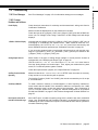
10.2 Wiring
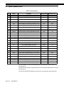
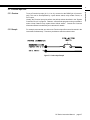
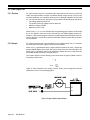
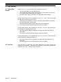
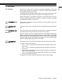
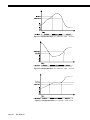
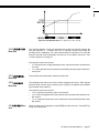
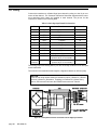
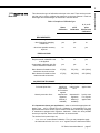
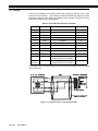
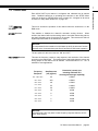
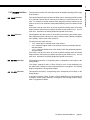
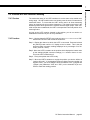
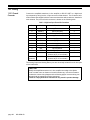
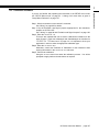
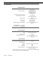
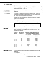
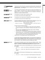
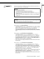
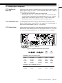
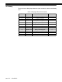
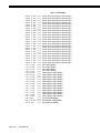
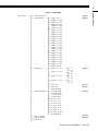
Connect the transducer to a Strain-Gage Input channel by wiring it to the 12-pin connector of that channel. The Customer Information Sheet that shipped with the instrument describes which cards are installed in each channel. The pin-out for this
connector is shown on the following table.
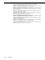
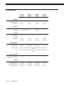
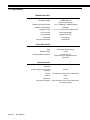
Table 4-3: Strain-Gage Input Channel Pin Connections
Pin
Label
Function
Reference Pin
1 (top)
+EXC
(+)Excitation
10
2
+SEN
(+)Sense
10
3
-SEN
(-)Sense
10
4
-EXC
(-)Excitation
10
5
+SIG
(+)Signal
10
6
-SIG
(-)Signal
10
7
+OUT
Analog Output
8
8
-OUT
Analog Return
-
9
+MEM
(+)Signature
10
10
-MEM
(-)Signature / Digital Ground
-
11
AUX1
Auxiliary Function 1
(connect to pin 10 to activate)
10
12
(bottom)
AUX2
Auxiliary Function 2
(connect to pin 10 to activate)
10
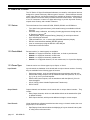
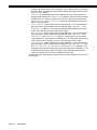
The Analog Output and Analog Return pins are electrically isolated from all other pins
on the instrument.
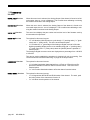
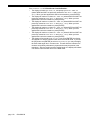
The maximum recommended cable length to a Signature Module is 100 feet [30m].
NOTICE
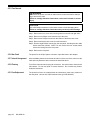
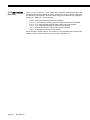
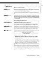
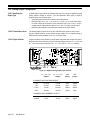
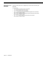
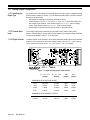
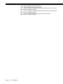
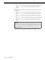
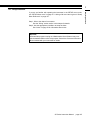
If you are not using remote sensing of excitation, jumper (+)Sense to (+)Excitation and (-)Sense to (-)Excitation. If nothing is connected to (+)Sense and ()Sense, the instrument will enter the ERROR mode with error code 46.
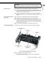
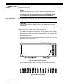
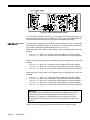
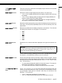
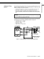
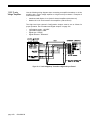
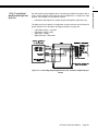
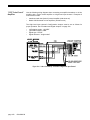
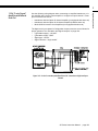
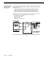
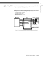
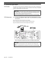
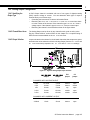
Figure 10-1: Unamplified Transducer Connection to Strain-Gage Input Channel
page 60
008-0608-00