1
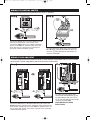
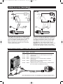
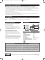
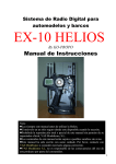
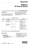
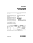
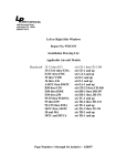
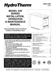
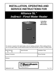
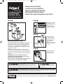
Model 1100 Instructions: Model 1100 Instructions
4/30/12
10:24 AM
Page 1
• ADVANCED SOLID STATE DESIGN
Model 1100
Low Water Cut-Off
For Residential
Hot Water Boilers
24 VAC Operating Voltage
• TEST BUTTON FOR EASY DIAGNOSTICS
• POWER AND LOW WATER LED INDICATORS
• MOLEX CONNECTOR FOR EASY WIRING
• COMPACT SIZE ALLOWS FOR MOUNTING IN TIGHT SPACES
Step �
Step �
Apply Teflon® tape to
the threads of the
Model 1100. Do not
use pipe dope or
other pipe sealants.
Step �
Determine Mounting Location
The Safgard 1100 must be installed at or above the
minimum safe water level established by the boiler
manufacturer. The 1100 can be installed directly into
the boiler if a suitable tapping is available 훽. The
1100 can also be installed in the boiler piping using a
standard 3/4" tee 훾.
Note: When installing in piping, select a location
close to the boiler to ensure the 4' wiring harness will
reach the 24-Volt transformer. The cut-off should be
installed on the boiler side of the circulator or shut-off
valves.
IMPORTANT: Check for adequate clearance
(minimum 1/4") from metal probe sensor to any
surface inside the boiler or pipe.
Do not install in a location that could hold or trap
water in the event of a low water condition.
Hand tighten the
control into boiler
tapping or pipe tee.
Be careful not to
cross thread.
Note: Do not use a
wrench. Hand tighten only.
Step �
Plug wire harness
into connector on
face of control.
Electrical shock hazard. To prevent electrical shock, death or
equipment damage, disconnect power supply before
WARNING
installing or servicing control. Only qualified personnel may install or service this control in
To prevent serious
CAUTION
burns, boiler
should be thoroughly cooled before installing or
accordance with local codes and ordinances. Read instructions completely before proceeding.
servicing control.
Frozen pipes/water damage. Central heating systems are prone to shut down as a result of power or fuel outages,
safety related fault conditions or equipment failure. Installation of freeze protection monitoring or other precautions
WARNING
is recommended for unattended dwellings in climates subject to sustain below-freezing temperatures.
83 Water Street • New Haven, CT 06511 • Phone (203) 776-0473 • FAX (203) 773-1019 • www.hydrolevel.com
Model 1100 Instructions: Model 1100 Instructions
4/30/12
10:24 AM
Page 2
WIRING TO CONTROL CENTER
For boilers equipped with a Honeywell R8285 Control Center or equivalent
Step �
Step �
®
Connect the WHITE wire to C and the RED wire to R
using the screw terminals on the control center.
Connect the GREEN wire to any suitable, unpainted
ground screw. Note: for operation of the control, the
green wire must be connected to a ground source
electrically common with boiler ground.
햲 Unplug the factory-wired quick connect from terminal R and 햳 plug into YELLOW wire with male
connector. 햴 Plug YELLOW wire with female con-
nector into terminal R.
WIRING TO AN AQUASTAT
For boilers equipped with a Honeywell Model L8148E or L8124E Aquastat. Safgard Model 1100 is not to be used with
Model L8148C or L8124C. Safgard Model 1150 should be used for oil-fired boilers.
Step �
Step �
햲 Unplug the factory-wired quick
connect from terminal B1 and 햳 plug
Connect the WHITE wire to TV and the RED wire to Z. Connect the
GREEN wire to the ground screw on the bottom of the aquastat or any
other suitable, unpainted ground screw. Note: for operation of the control, the green wire must be connected to a ground source electrically
common with boiler ground.
into YELLOW wire with male connector. 햴 Plug YELLOW wire with female
connector into terminal B1.
UPON COMPLETION OF WIRING,
REPLACE COVER.
Model 1100 Instructions: Model 1100 Instructions
4/30/12
10:24 AM
Page 3
WIRING TO 24 VAC TRANSFORMER
For boilers using a standard 24 VAC transformer
Step �
Step �
Connect RED wire to hot side of 24 Volt boiler transformer (R). Connect WHITE wire to common side of
24 Volt boiler transformer (C). Connect the GREEN
wire to any suitable, unpainted ground screw.
Note: for operation of the control, the green wire
must be connected to a ground source electrically
common with boiler ground.
Cut-off the connectors and strip the ends of the two
yellow wires of the Model 1100 harness. Break into
the burner circuit between the hot side of the transformer (R) and other limit controls. Connect either
YELLOW wire to the hot side. Connect the other
YELLOW wire in series with other limit controls.
Important: The switch contacts of the low water cutoff (yellow wires) must be wired in series with all
other limit and operating controls (as shown above).
BOILER SPECIFIC MODELS AND WIRE HARNESSES
Part No. Model
45-1100 1100
45-1102 1100H2
45-1103
45-1104
45-1105
45-1106
1100H3
1100H4
1100H5
1100H6
Description
1100 with standard wire harness (cable 45-531-54)
1100 with wire harness for UTC intergrated control module
(cable 45-348)
1100 without wire harness
1100 with wire harness for Burnham Alpine, SCG/PVG
(cable 45-350)
1100 with wire harness for Weil McLain Ultra, Lochinvar
Knight & Solution (cable 45-349)
1100 with wire harness for Burnham Series 2, PVGA, PVCGA,
New Yorker CG-D and PVCGA (cable 45-347)
1100H2
Including 45-348 Harness
Note: Wire Harnesses are also sold separately (use cable part numbers above)
Model 1100 Instructions: Model 1100 Instructions
4/30/12
10:24 AM
Page 4
OPERATIONAL TEST PROCEDURE
IMPORTANT: Do not run boiler unattended until the following procedure is completed
1. Before raising the water level above the Model 1100, turn on power to the boiler and set the thermostat to call for heat. Both the green
“POWER” LED and amber “LOW WATER” LED should illuminate. The burner should not fire. IMPORTANT: If the burner fires with no water
at the probe, immediately shut down power to the boiler and refer to the Trouble Shooting instructions below.
2. Proceed to fill the boiler with water. When water reaches the LWCO position, the burner should fire. If the burner does not fire, refer to the
Trouble Shooting instructions below.
3. Turn off the power to the boiler and finish filling the system.
4. Before leaving the job, power up the system and push the TEST button on the Model 1100 to simulate a low water condition. The amber
“LOW WATER” LED should illuminate and the burner should shut down.
MAINTENANCE
EVERY YEAR
Check control operation annually by pressing the TEST button. The amber “LOW WATER” LED should illuminate and the
burner should shut down.
5 YEARS
Remove the low water cut-off every five years and clean all surfaces in contact with water.
TROUBLE SHOOTING
IF THE BURNER DOES NOT SHUT DOWN
DIMENSIONS
(when water is below the probe or
when the TEST button is pressed)
1. Turn off boiler power immediately and re-check wiring.
2. Turn off boiler power and drain system. Remove low water cutoff and check for adequate clearance – no metal should be in
contact with the control’s metal probe tip.
IF THE BURNER DOES NOT FIRE
1. Make sure water has reached the level of the control.
2. Check green wire for proper ground. Make sure the wire is
attached to an unpainted surface that is electrically common to
the boiler.
3. Check to ensure the control’s metal probe tip is not surrounded
by an air pocket. Shut down power to the boiler and slowly
loosen, but do not remove, the control. Allow any air to escape.
When water begins to seep past threads, retighten the control.
4. Re-check wiring and check for correct incoming voltage.
SPECIFICATIONS
VOLTAGE
24 VAC
MAX LOAD
5 Amps
POWER CONSUMPTION
SWITCHING CAPACITY
MAX PRESSURE
MAX WATER TEMPERATURE
MAX AMBIENT TEMPERATURE
1 VA
50 VA
160 PSI (11.25 kg/cm2)
250°F (121°C)
170°F (77°C)
LIMITED MANUFACTURERʼS WARRANTY
We warrant products manufactured by Hydrolevel Company to
be free from defects in material and workmanship for a period
of two years from the date of manufacture or one year from
the date of installation, whichever occurs first. In the event of
any claim under this warranty or otherwise with respect to our
products which is made within such period, we will, at our
option, repair or replace such products or refund the purchase
price paid to us by you for such products. In no event shall
Hydrolevel Company be liable for any other loss or damage,
whether direct, indirect, incidental or consequential. This warranty is your EXCLUSIVE remedy and shall be IN PLACE OF
any other warranty or guarantee, express or implied, including, without limitation, any warranty of MERCHANTABILITY or
fitness for a particular purpose. This warranty may not be
assigned or transferred and any unauthorized transfer or
assignment thereof shall be void and of no force or effect.
83 Water Street • New Haven, CT 06511 • Phone (203) 776-0473 • FAX (203) 773-1019 • www.hydrolevel.com
1100-0512