1
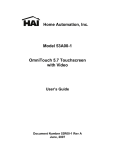
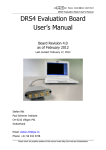
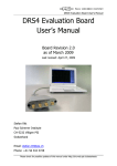
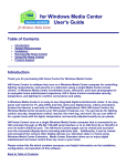
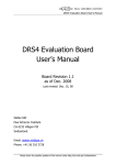
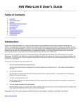
Home Automation, Inc.
Model 53A00-1
OmniTouch 5.7 Touchscreen
with Video
Installation Manual
Document Number 53I00-1 Rev A
June, 2007
FCC NOTICE
This device complies with FCC Rules Part 15. Operation is subject to the following two
conditions: (1) This device may not cause harmful interference, and (2) This device must
accept any interference received, including interference that may cause undesired operation.
Verified to comply with the limits of a Class B digital device pursuant to Part 15 of the FCC
Rules.
Copyright © 2007 Home Automation, Inc.
ALL RIGHTS RESERVED
PLANNING
It is very important to plan where the OmniTouch 5.7 Touchscreen will be installed and the
gauge/type of wire you will use for the installation. The touchscreen can be connected directly
to the HAI controller if video is not being used. However, if video is being used, the
touchscreen must be connected to the HAI Touchscreen Hub. The HAI Touchscreen Hub can
also be used if you are connecting multiple touchscreens (up to 8).
In selecting a place to mount the touchscreen, be sure to avoid an area where studs, plumbing,
or electrical wiring may be located behind the wallboard. It should be mounted so that the
display is at or slightly above eye level.
Wiring to the HAI Controller
When connecting the touchscreen directly to the HAI controller, run the power/communications
cable (as determined by Table 1) from the controller location to touchscreen location. A
minimum of 4 wires is required for operation (2 for power and 2 for communications). The
required distance between the controller and the touchscreen will determine the wire gauge/type
you should use. To prevent the touchscreen from drawing more than the specified maximum
current from the controller’s power supply, do not exceed the "Maximum Cable Length" based
on the wire gauge/type per the table below (Table 1).
MAXIMUM CABLE LENGTH BASED ON WIRE GAUGE / TYPE
Wire
Gauge
Solid/
Number of positive
Stranded
conductors
Number of ground
conductors
Maximum Cable
Length (feet)
24
24
24
solid
solid
solid
1
2
3
1
2
3
113
227
340
22
22
22
solid
solid
stranded
1
2
1
1
2
1
180
360
166
20
20
solid
stranded
1
1
1
1
287
267
18
18
solid
stranded
1
1
1
1
456
420
16
16
solid
stranded
1
1
1
1
724
669
Table 1
1
If cable with multiple conductors is used (such as Cat-5 cable), it is possible to connect multiple
conductors together to achieve greater distance. For example, using only one of the 24 gauge
conductor in the Cat-5 cable for power (1 for positive and 1 for ground), the maximum distance
between the controller and the touchscreen is 113 feet. If you were to connect 2 of the 24 gauge
conductors together (2 for positive and 2 for ground), the maximum distance between the
controller and the touchscreen is then 227 feet. If you were to connect 3 of the 24 gauge
conductors together (3 for positive and 3 for ground), the maximum distance between the
controller and the touchscreen is then 340 feet.
Wiring to the HAI Touchscreen Hub
When connecting the touchscreen to the HAI Touchscreen Hub, a Cat-5 (4-pair) cable is
required for operation. The Cat-5 cable provides power, communications, and the video signal
from the HAI Touchscreen Hub to the touchscreen.
Run the Cat-5 cable between the HAI Touchscreen Hub location and the touchscreen location.
The maximum distance between the controller and each touchscreen is 800 feet. Terminate
both ends of the Cat-5 cable with an 8-position modular connector (as if to make a standard
network cable).
Note: When calculating the distance between the Touchscreen Hub and a touchscreen, you
must subtract the distance between the Touchscreen Hub and the HAI controller from the total
distance. For example, if the Touchscreen Hub is 100 feet from the controller, the maximum
distance between the Touchscreen hub and each touchscreen is 700 feet.
CONNECTING TO THE HAI TOUCHSCREEN HUB
When used, each OmniTouch Touchscreen connects to the HAI Touchscreen Hub. The HAI
Touchscreen Hub provides power, communications, and the video signal to the touchscreen.
Each HAI Touchscreen Hub can support a maximum of 8 touchscreens.
Note: When more than 8 OmniTouch Touchscreens are used, a second HAI Touchscreen Hub
with Video Encoder (if video is being used) is required. See the HAI Touchscreen Hub
Installation Manual for more details.
Connections:
When connecting a touchscreen to the HAI Touchscreen Hub, insert the 8-position modular
cable, coming from the touchscreen, into one of the RJ-45 connectors (J1-J8) on the HAI
Touchscreen Hub.
See the HAI Touchscreen Hub Installation Manual for complete installation instructions.
2
INSTALLATION
1) Make the cutout for the touchscreen
Hold the template (Installation Template – 53A10-1) against the wall so the top edge is at
the appropriate height and parallel to the floor. Using a Punch, or similar instrument, punch
through the center of each tick mark (+) on the template.
Drill a 1/4" hole at each punch mark. Using a pencil, draw a line around the quadrant of
each hole as shown as shown. Carefully cut along the pencil line.
DO NOT OVERSIZE THIS CUTOUT!
Figure 1
2) Remove the faceplate
Remove the faceplate from the touchscreen by grasping the top and bottom edges of the
faceplate and carefully lifting it away from touchscreen backbox.
Note: After installation, the faceplate may be removed by placing a flat blade screwdriver in
one of the slots on the bottom of the faceplate and gently lifting to release the latch on the
respective side. Repeat by using the slot on the opposite side.
FACEPLATE - BOTTOM VIEW
LATCH RELEASE SLOTS
Figure 2
3
3) Remove the touchscreen assembly from the backbox
a. Remove the two screws as shown in Figure 3 (DO NOT REMOVE THE SCREWS
ON THE GREEN CIRCUIT BOARD). Retain screws for reassembly.
b. Remove the touchscreen assembly as shown in Figure 3.
Figure 3
4) Install the backbox into the cutout in the wall
a. Insert the communications cable through the rectangular cutout in the touchscreen
backbox.
b. Locate the retaining flange screws in the upper right and lower left corners. Turn the
screws counterclockwise until the gap between the retaining flange and the housing
flange is wider then the wall (see Figure 4).
TOUCHSCREEN BACKBOX
TOP VIEW
Figure 4
4
c. Place the assembled unit into the cutout in the wall.
d. Turn the retaining flange screws clockwise until they are snug (do not over tighten).
WALL
Figure 5
5) Terminate the communications cable
a. When connecting the touchscreen directly to the HAI controller, use the supplied
8-position modular cable assembly. Attach the wires coming from the controller to
the supplied cable assembly using the supplied wire spice connectors.
b. When connecting the touchscreen to the HAI Touchscreen Hub, terminate the cable
with an 8-position modular connector (as if to make a standard network cable).
6) Connect the communications cable to the touchscreen
Insert the 8-position modular cable into the RJ-45 connector (J1) on the touchscreen, through
the cutout in the touchscreen backbox (see Figure 6).
5
Figure 6
7) Install the touchscreen assembly
a. Align the tabs on the touchscreen assembly with the slots on the backbox.
Figure 7
6
b. Swing the touchscreen assembly in place and secure to backbox using screws that
were removed in Step 3.
Figure 8
8) Install the touchscreen faceplate
Before installing faceplate, remove the protective film from the LCD area of the
touchscreen. Fasten the faceplate onto the touchscreen by hanging the top of the faceplate
on the top edge of the touchscreen, then gently snapping the bottom onto the touchscreen.
REMOVING THE TOUCHSCREEN
After installation, if it is necessary to remove the touchscreen from the wall, turn retaining
flange screws 1 turn counterclockwise.
Note: Do not turn the retaining flange screws more than 1 full turn counterclockwise; otherwise
the retaining flange may fall off into the wall.
7
CONNECTING TO OMNI IIe, LUMINA, OMNIPRO II, AND LUMINA PRO
Connect the "Yellow" and "Green" wires from the touchscreen to the "A" and "B" terminals
under the section marked "CONSOLE" on the controller, respectively. Connect the "Red" and
"Black" wires from the touchscreen to the "12V" and "GND" terminals under the section
marked "AUXILIARY" on the controller, respectively.
A maximum combination of 8 touchscreens and consoles can be used with Omni IIe or Lumina
and a maximum combination of 16 with OmniPro II or Lumina Pro.
NOTE: Do not exceed the maximum current limitation of the controller. If more than 2
touchscreens are used, the additional touchscreens must be powered from an external
power supply or HAI Touchscreen Hub.
GREEN
BLACK
YELLOW
RED
THE EXTERNAL POWER SUPPLY MUST BE GROUNDED TO THE CONTROLLER
EARTH GROUND TO AVOID DAMAGE TO THE TOUCHSCREEN.
BLACK
RED
GREEN
YELLOW
CONNECT ENDS OF SUPPLIED
CABLE TO CORRESPONDING ENDS
OF THE POWER/COMMUNICATION
CABLE FROM THE CONTROLLER
SUPPLIED CABLE
(PLUGS INTO J1)
Omni IIe, Lumina, OmniPro II, and Lumina Pro Connections
8
CONNECTING TO OMNILT
Connect the "Yellow" and "Green" wires from the touchscreen to the "YEL" and "GRN"
terminals under the section marked "CONSOLE" on the controller, respectively. Connect the
"Red" and "Black" wires from the touchscreen to the "12V" and "GND" terminals under the
section marked "AUX" on the controller, respectively.
A maximum combination of 4 touchscreens and consoles can be used with OmniLT.
NOTE: Do not exceed the maximum current limitation of the controller. If more than 1
touchscreen is used, the additional touchscreens must be powered from an external power
supply or HAI Touchscreen Hub.
GREEN
YELLOW
BLACK
RED
THE EXTERNAL POWER SUPPLY MUST BE GROUNDED TO THE CONTROLLER
EARTH GROUND TO AVOID DAMAGE TO THE TOUCHSCREEN.
BLACK
RED
GREEN
YELLOW
CONNECT ENDS OF SUPPLIED
CABLE TO CORRESPONDING ENDS
OF THE POWER/COMMUNICATION
CABLE FROM THE CONTROLLER
SUPPLIED CABLE
(PLUGS INTO J1)
OmniLT Connections
9
ADDRESSING THE TOUCHSCREEN
OmniTouch touchscreens are connected to the same communications bus as HAI consoles.
Each console and touchscreen must have a unique address. The default address setting of the
touchscreen is "1".
When power is first connected to the touchscreen, if the touchscreen isn’t addressed properly
(other consoles or touchscreens already occupy the touchscreen address) or isn’t communicating
with the controller, the following page is displayed.
To assign an address to the touchscreen, press and hold the HAI logo for three seconds. The
"Touchscreen Address" page is displayed.
This page allows the installer to adjust the brightness and contrast of the touchscreen, enable or
disable video, and assign the touchscreen address.
10
Brightness and Contrast
Press the [up arrow] button to raise the current brightness or contrast setting. Press the [down
arrow] button to lower the current setting.
Video
If the touchscreen is connected to the HAI Touchscreen Hub with Video Encoder, press the
[up arrow] button to enable video on the touchscreen. If not, press the [down arrow] button to
disable video.
When Video is enabled, the Video icon will be displayed on the Home page. If it is disabled,
the Setup button will be displayed instead.
Touchscreen Address
Use the [up arrow] and [down arrow] buttons to set the touchscreen address.
When complete, press the [exit] button in the lower-right corner to save the settings and exit.
Once the touchscreen is properly configured and communicating with the controller, other
configuration items may be configured using the "Screen Setup" page. To access the "Screen
Setup" page, from the Home page (if Video is disabled) or the System page, touch the [Setup]
icon. See the Touchscreen User’s Guide (53R00-1) for additional information on these items.
Note: In the event of an AC Power failure and the HAI controller is running on backup battery
power, the touchscreen display will be lowered to its lowest viewable setting. Do not try to
adjust the “brightness” and “contrast” levels. When AC Power is restored, the touchscreen
display will automatically return to its correct settings.
RESETTING THE TOUCHSCREEN
If for any reason the touchscreen needs to be reset, remove the faceplate and press the reset
button marked "SW1" on the circuit board to the right of the LED.
11
UPDATING THE TOUCHSCREEN
The USB Update Port on the OmniTouch 5.7 allows you to update the touchscreen with the
latest firmware and screens. This allows you to take advantage of new touchscreen features and
new screens that support features of updated controller firmware. The Update Port is a USB
port in the lower right section of the touchscreen.
USB
UPDATE PORT
Load the update file on a USB thumb drive. Plug the thumb drive into the USB Update Port on
the OmniTouch 5.7 Touchscreen. When the USB drive is plugged into the port, the touchscreen
will read the files on the root directory of the drive and display any applicable update files.
Select the desired file from the list and then press the “Next” button. Follow the instructions on
the screen.
12
SPECIFICATIONS
Size:
Backbox cutout:
Faceplate:
LCD View Area:
5.625" W x 5.125" H
6" W x 5.5" H
4.626" W x 3.492" H
Voltage:
Operating Voltage: 10 – 24 VDC
Maximum Current Consumption at 12 VDC:
300 mA based on Maximum Cable Length as defined in "Table 1"
Maximum Current Consumption at 24 VDC:
200 mA based on Maximum Cable Length of 800 feet
Maximum CAT-5 Cable Length AT 24 VDC:
13
800 feet