1
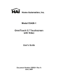
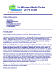
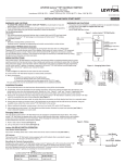
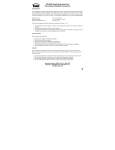
HOME AUTOMATION, INC.
Model 32A30
Touchscreen Hub
Installation Manual
Document Number 32I30-1 Rev B
March, 2008
Copyright © 2005-2008 Home Automation, Inc.
All Rights Reserved
INTRODUCTION
The HAI Touchscreen Hub is used to provide power, communications, and a video signal to HAI
OmniTouch touchscreens. Up to eight (8) OmniTouch touchscreens, with or without video, can be
connected; however, you may connect an additional Touchscreen Hub for a total of up to 16 OmniTouch
touchscreens when used with an HAI OmniPro II or HAI Lumina Pro controller. The Touchscreen Hub
is required for connecting OmniTouch with Video touchscreens.
The HAI Touchscreen Hub provides battery backed power for HAI OmniTouch touchscreens, cameras
(optional), and the HAI Video Encoder. It has convenient connections and power terminals for a neat
installation. It also has six individual camera inputs, which can be selected by the HAI OmniTouch
Touchscreen with Video for viewing. Six individual camera outputs allow the cameras to be connected
to a second HAI Touchscreen Hub with Video Encoder, HAI Web-Link II for viewing on a monitor or
handheld device, HAI Home Control for Windows Media Center for viewing and recording, and/or
directly to television sets, video recorders, etc.
The HAI Touchscreen Hub was designed to eliminate unsightly transformers, power strips, external
power supplies, battery backup units, and complex wiring normally associated with camera and
touchscreen installations. In addition to simplifying the installation, the HAI Touchscreen Hub
automatically sequences the startup of touchscreens and has a low voltage cut out feature for long term
reliability and zero maintenance.
GENERAL
The HAI Touchscreen Hub is available in an HAI Omni Series Enclosure or on the HAI Universal
Mounting Plate for installation in Structured Wiring enclosures. It is supplied with a sealed Power Pack,
which provides power to the HAI Touchscreen Hub.
Features:
1. Connections for 8 touchscreens: Cat 5 (RJ-45) for HAI OmniTouch 5.7 (53A00-1), HAI OmniTouch
with Video (32A00-5) and 4-position terminals for HAI OmniTouch (32A00-1)
2. Inputs from 6 NTSC Composite color or b/w cameras
3. Pass-through outputs for 6 cameras to TV, modulator, media center, other displays, etc.
4. Power supply with battery back up for touchscreens and cameras
5. Connections for all Omni and Lumina controllers
6. Supports Video Encoder (mounts on Touchscreen Hub circuit board), required for video
7. Supervisory output can be connected to Omni zone to indicate low battery
8. Connectors for two sealed batteries, 12 V at 4 to 8 amp-hours each (not supplied)
9. Supplied with Universal Switching Power Pack
HAI Video Encoder
The HAI Video Encoder mounts onto the Touchscreen Hub. It digitizes video signals from the
connected cameras and sends it to OmniTouch with Video touchscreens for viewing. It can be
purchased bundled and factory installed on the Touchscreen Hub or added later in the field. The HAI
Video Encoder is required to view video on OmniTouch with Video touchscreens.
INSTALLATION
NOTE: This unit has protection against static discharge in normal operation. However, use static
discharge precautions during installation. Always touch the enclosure to discharge static before
touching the connections.
NOTE: Do not make changes to terminal lock connections (TB1 – TB6) with power on! Disconnect
power AND batteries first.
1. GROUNDING
Each Touchscreen Hub MUST be grounded to the controller. The HAI controller and HAI
Touchscreen Hub(s) must be grounded together to prevent any current from flowing through the
RS-485 data bus (connections A and B). If not grounded properly, damage could occur to the HAI
controller, HAI Touchscreen Hub, and/or OmniTouch touchscreens.
Connect the “GND” terminal on the HAI Touchscreen Hub under the section marked
“CONTROLLER”, to one of the “GND” terminals on the HAI controller.
2. COMMUNICATIONS CONNECTIONS
Connect the terminals labeled “A” and “B” on the HAI Touchscreen Hub under the section marked
“CONTROLLER”, to the “A” and “B” terminals on the HAI controller.
Note: When connecting to an OmniLT, the terminal labeled “A” on the Touchscreen Hub connects to
the “YEL” terminal and the terminal labeled “B” on the Touchscreen Hub connects to the ”GRN”
terminal under the section marked “CONSOLE” on the OmniLT controller.
The HAI Touchscreen Hub may be located in a remote location up to 800 feet from the HAI controller.
A
A
A = MOUNTING HOLES FOR VIDEO ENCODER
A
A
OMNITOUCH (32A00-1)
OMNITOUCH 5.7 (53A00-1)
OMNITOUCH WITH VIDEO(32A00-5)
TERMINAL BLOCKS
CAT 5 CONNECTORS
CAMERA
INPUT
CAMERA POWER
1.5A MAXIMUM
TERMINATING
RESISTOR
JUMPER
CAMERA OUTPUT
*
A / YELLOW
B / GREEN
*
GND(GROUND)
GND MUST BE CONNECTED
TO GND ON HAI CONTROLLER
HAI CONTROLLER
ZONE(-)
ZONE(+)
3. LOW BATTERY INDICATOR (Optional Connection)
When the backup batteries connected to the Touchscreen Hub become depleted, there are terminals on
the Touchscreen Hub that are used to send a signal to the HAI controller to alert you of the low battery
condition. To take advantage of this feature, you must have an extra pair of wire between the
Touchscreen Hub and the HAI controller, and an available zone on the HAI controller.
Connect the terminals labeled “LB+” and “LB-” under the section marked “CONTROLLER” on the
Touchscreen Hub to the “+” and “-” zone terminals of an available zone on the HAI controller. Do not
use an end-of-line resistor on the zone. The touchscreen has a built-in 1K ohm resistor for this output.
Configure the zone as a “Trouble” zone.
When the batteries on the Touchscreen Hub fall below a certain voltage threshold, the terminals “LB+”
and “LB-” will open causing the zone on the HAI controller to trip, indicating a low battery condition on
the Touchscreen Hub.
4. TOUCHSCREEN CONNECTIONS
Connections to touchscreens are divided into 4 different areas, labeled: “Touchscreens 1 & 2”,
“Touchscreens 3 & 4”, “Touchscreens 5 & 6”, and “Touchscreens 7 & 8”. Each area can have a
maximum of 2 touchscreens connected in it. OmniTouch 5.7 (53A00-1) and OmniTouch with video
(32A00-5) are connected to the Category 5 connectors. OmniTouch (32A00-1) is connected to the
terminal block (red, black, yellow, green).
Connections to OmniTouch with Video (32A00-5), OmniTouch 5.7 (53A00-1)
These touchscreens require Cat-5 (4-pair) cable for operation. The Cat-5 cable provides power,
communications, and the video signal from the HAI Touchscreen Hub to the touchscreen.
Run the Cat-5 cable between the touchscreen and the HAI Touchscreen Hub. The maximum distance
between the Touchscreen Hub and each touchscreen is 800 feet.
Note: When calculating the distance between the Touchscreen Hub and a touchscreen, you must
subtract the distance between the Touchscreen Hub and the HAI controller from the total distance. For
example, if the Touchscreen Hub is 100 feet from the controller, the maximum distance between the
Touchscreen hub and each touchscreen is 700 feet.
Terminate both ends of the Cat-5 cable with an 8-position modular connector (as if to make a standard
network cable).
Connect the OmniTouch Touchscreen to the HAI Touchscreen Hub, by inserting the modular connector
into the touchscreen and into one of the RJ-45 connectors (J1-J8) on the HAI Touchscreen Hub.
Note: Do not connect more than 2 touchscreens in a given area (see “Touchscreen Connections”).
Connecting to OmniTouch (32A00-1)
When connecting a standard OmniTouch to the Touchscreen Hub, it is very important to plan where the
OmniTouch touchscreen will be installed and the gauge/type of wire you will use for the installation.
The touchscreen requires a minimum of 4 wires for operation (2 for power and 2 for communications).
The required distance between the Touchscreen Hub and the touchscreen will determine the wire
gauge/type you should use. To prevent the touchscreen from drawing more than the specified maximum
current from the Touchscreen Hub, do not exceed the "Maximum Cable Length" based on the wire
gauge/type according to the “Table 1”.
TABLE 1
MAXIMUM CABLE LENGTH BASED ON WIRE GAUGE / TYPE
Wire
Gauge
24
24
24
22
22
22
20
20
18
18
16
16
Solid/
Stranded
solid
solid
solid
solid
solid
stranded
solid
stranded
solid
stranded
solid
stranded
Number of positive
conductors
1
2
3
1
2
1
1
1
1
1
1
1
Number of ground
conductors
1
2
3
1
2
1
1
1
1
1
1
1
Maximum Cable
Length (feet)
398
800
1000
634
1000
585
1000
904
1000
1000
1000
1000
If cable with multiple conductors is used (such as Cat-5 cable), it is possible to connect multiple
conductors together to achieve greater distance. For example, using only one of the 24 gauge conductor
in the Cat-5 cable for power (1 for positive and 1 for ground), the maximum distance between the
controller and the touchscreen is 398 feet. If you were to connect 2 of the 24 gauge conductors together
(2 for positive and 2 for ground), the maximum distance between the controller and the touchscreen is
then 800 feet. If you were to connect 3 of the 24 gauge conductors together (3 for positive and 3 for
ground), the maximum distance between the controller and the touchscreen is then 1000 feet.
Note: The distance between the Touchscreen Hub and HAI controller combined with the distance
between the Touchscreen Hub and a touchscreen, must never exceed a maximum distance of 1000 feet.
When calculating the distance between the Touchscreen Hub and a touchscreen, you must subtract the
distance between the Touchscreen Hub and the HAI controller from the “Maximum Cable Length” as
listed in “Table 1”.
Connect the "Red", "Black", "Yellow", and "Green" wires from the touchscreen to the “RED”, “BLK”,
"YEL" and "GRN" terminals on the Touchscreen Hub, respectively.
Note: Do not connect more than 2 touchscreens in a given area (see “Touchscreen Connections”).
5. CAMERA CONNECTIONS
The Touchscreen Hub takes the composite signal from any NTSC camera, digitizes it through the
encoder, and then broadcasts it to the connected OmniTouch with Video or OmniTouch 5.7
touchscreens. The Touchscreen Hub supports 6 individual cameras. In the areas marked CAMERA 1 –
CAMERA 6, there is a connector for the camera input (to connect the camera) and the camera output (to
connect the video signal to additional devices).
Camera Inputs
Connect NTSC composite cameras to the RCA connectors marked J9 (Camera 1), J11 (Camera 2),
J13 (Camera 3), J15 (Camera 4), J17 (Camera 5), and J19 (Camera 6) on the Touchscreen Hub.
Each camera input has a terminating resistor installed at the factory for optional video performance. If
the corresponding camera output is not being used, make sure that the respective terminating resistor
jumper (J21 - J26) is installed (this is the default position from the factory).
Camera Outputs
Each of the 6 camera inputs also has a pass-though output. These outputs are used to connect a second
HAI Touchscreen Hub, HAI Web-Link II for viewing on a monitor or handheld device, HAI Home
Control for Windows Media Center for viewing and recording, and/or directly to television sets, video
recorders, etc.
Using the on-board RCA connectors, connect camera outputs marked J10 (Camera 1), J12 (Camera 2),
J14 (Camera 3), J16 (Camera 4), J18 (Camera 5), and J20 (Camera 6) to your additional source device(s)
(e.g. video modulator, second HAI Touchscreen Hub, etc.).
When the video output is being used to connect a second source, remove the corresponding terminating
resistor jumper J21 – J26.
Camera Power
The Touchscreen Hub has terminals to provide camera power to 12 VDC cameras. The camera power
supply is also battery backed; however, this can be disabled so that the connected touchscreens run
longer on the backup battery.
To power a 12 VDC camera from the Touchscreen Hub, connect the camera’s power leads to the
terminals labeled “12V” and “GND” under the section marked “Camera Power”, observing proper
polarity. The camera power supply can supply a maximum of 1.5 A to the connected cameras.
By default, the Touchscreen Hub is set to battery backup camera power when AC power is
disconnected. To disable the battery backup of camera power, set the jumper marked “J32” to the
“DISABLE” position (the leftmost and center pin). In this configuration, you will not be able to view
cameras when AC power is disconnected.
6. CONNECTING A SECOND HAI TOUCHSCREEN HUB
When connecting more than 8 OmniTouch with Video touchscreens to an HAI OmniPro II or HAI
Lumina Pro controller, a second Touchscreen Hub is required. To view video on the additional
OmniTouch with Video touchscreens (the ones connected to the second Touchscreen Hub), a Video
Encoder installed on the second Touchscreen Hub is required.
When connecting a second Touchscreen Hub, with the exception of cameras, make all other connections
as described in this document.
To view video on OmniTouch with Video touchscreens that are connected to the second Touchscreen
Hub with Video Encoder, connect the camera outputs from the first Touchscreen Hub to the camera
inputs on the second Touchscreen Hub. Make sure that you remove the corresponding terminating
resistor jumper J21 – J26 from the first Touchscreen Hub.
7. INSTALLING THE 32A32-2 HAI VIDEO ENCODER
If you have purchased the HAI Video Encoder separately from the Touchscreen Hub, install the Video
Encoder as follows:
1. Disconnect power and batteries.
2. Insert the short end of each of the 4 supplied nylon standoffs into the mounting holes on the
Touchscreen Hub. Make sure that the standoff snaps into the mounting holes.
3. With the pins (marked “J2 ALT”) on the Video Encoder faced down, align the mounting holes
on the Video Encoder with the installed standoffs on the Touchscreen Hub. Rest the Video
Encoder board on the standoffs.
4. Align the pins (marked “J2 ALT”) on the Video Encoder with the connector (marked “J27”) in
the Touchscreen Hub.
5. Gently push down so that the pins (marked “J2 ALT”) are firmly seated into the connector
(marked “J27”).
6. Push down on the Video Encoder board at the locations of each mounting hole, so that each of
the standoffs snaps into the mounting holes.
(Connections Diagram on Next Page)
32A30-1, -2, -3, -4
TOUCHSCREEN HUB
NYLON SPACER
32A32-2
VIDEO ENCODER
8. POWER CONNECTIONS
The supplied Power Pack provides both touchscreen (24VDC) and camera (12VDC) power. An AC
power outlet should be located within 5 feet. One or two sealed, rechargeable batteries (not included)
can be used to backup the touchscreen and camera (optional) power. The two battery cables are in
parallel, so by adding a second battery you will increase the battery backup time.
1. Connect one or two 12VDC batteries using the supplied battery terminals. Connect the BLACK
battery wire to the minus (-) terminal on the battery and connect the RED battery wire to the
plus (+) terminal on the battery. DO NOT reverse the connections; the battery fuse will blow.
Note that the unit will NOT START on the battery alone.
2. Plug the connector for the Power Pack into the mating connector of the HAI Touchscreen Hub
marked “J33”.
3. Plug the power cord from the Power Pack into a 120 VAC outlet. The “POWER ON” LED
should illuminate.
4. Unplug the Power Pack. The Touchscreen Hub should continue to run off of the battery
backup. The “POWER ON” LED should turn off.
Plug in the Power Pack. The system should start. The “POWER ON” LED should illuminate.
SPECIFICATIONS
Operating
Ranges:
32 - 120 degrees F (0 - 49 degrees C)
10 - 85 % relative humidity, non-condensing
Power Pack:
Output 19VDC, 3.79 Amps, Max 72W
Input 120VAC, 1.8A amps, 60Hz
Maximum Power:
72 Watts
Batteries:
Sealed, Rechargeable, 12 volts, 4 - 8 amp-hours each
Low Voltage Cut Out:
10VDC
Main Fuse:
5A Polyfuse
Battery Fuses:
5A Polyfuse
Polyfuses are permanent fuses that do not need replacement.
Camera Power:
Nominal Voltage 12VDC
Maximum Current 1.5A