1
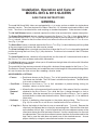
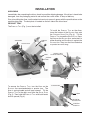
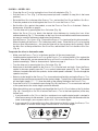
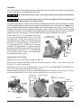
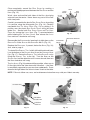
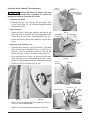
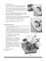
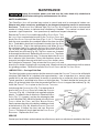
I
N
S
T
R
U
C
T
I
O
N
S
MODEL 3813 & 3913 SLICERS
MODELS
3813 Manual Slicer
ML-136135
3913 Automatic Slicer
ML-136145
701 S. RIDGE AVENUE
TROY, OHIO 45374-0001
937 332-3000
www.hobartcorp.com
FORM 35219 (Oct. 2007)
TABLE OF CONTENTS
GENERAL . . . . . . . . . . . . . . . . . . . . . . . . . . . . . . . . . . . . . . . . . . . 3
Accessories & Options . . . . . . . . . . . . . . . . . . . . . . . . . . . 3
INSTALLATION . . . . . . . . . . . . . . . . . . . . . . . . . . . . . . . . . . . . . . 4
Unpacking . . . . . . . . . . . . . . . . . . . . . . . . . . . . . . . . . . . . . 4
Product Tray . . . . . . . . . . . . . . . . . . . . . . . . . . . . . . . . . . . 4
Sharpener . . . . . . . . . . . . . . . . . . . . . . . . . . . . . . . . . . . . . 5
Top Knife Cover . . . . . . . . . . . . . . . . . . . . . . . . . . . . . . . . . 5
Electrical. . . . . . . . . . . . . . . . . . . . . . . . . . . . . . . . . . . . . . . 5
Clean Before Using . . . . . . . . . . . . . . . . . . . . . . . . . . . . . . 5
OPERATION . . . . . . . . . . . . . . . . . . . . . . . . . . . . . . . . . . . . . . . . . 6
Slicing — Model 3813 . . . . . . . . . . . . . . . . . . . . . . . . . . . . 6
Slicing — Model 3913 . . . . . . . . . . . . . . . . . . . . . . . . . . . . 7
Cleaning . . . . . . . . . . . . . . . . . . . . . . . . . . . . . . . . . . . . . . . 8
Cleaning the Knife in Place . . . . . . . . . . . . . . . . . . . . . . . . 8
Using the Knife Removal Tool Accessory . . . . . . . . . . . 10
Reassemble Slicer Parts . . . . . . . . . . . . . . . . . . . . . . . . . 11
MAINTENANCE . . . . . . . . . . . . . . . . . . . . . . . . . . . . . . . . . . . . . 12
Knife Sharpening . . . . . . . . . . . . . . . . . . . . . . . . . . . . . . . 12
Lubrication — Carriage Slide Rod . . . . . . . . . . . . . . . . . 12
Service . . . . . . . . . . . . . . . . . . . . . . . . . . . . . . . . . . . . . . . 12
© HOBART CORPORATION 2007
–2–
Installation, Operation and Care of
MODEL 3813 & 3913 SLICERS
SAVE THESE INSTRUCTIONS
GENERAL
The model 3813 and 3913 slicers are equipped with a 1⁄2 HP motor and are available for single-phase
electrical service. The slicer features the Hobart CleanCut 13" diameter contoured stainless steel
knife. The slicer is furnished with a cord and plug as standard equipment. Other features include:
TM
The No Volt Release feature, standard, requires the slicer to be restarted after a power interruption.
The Gauge Plate Interlock feature, standard, prevents the PRODUCT TRAY (Fig. 1) from being tilted or
removed unless the PRODUCT TRAY is in the home position (pulled all the way toward you) and the GAUGE
PLATE is closed. Note also that the slicer will not start unless the KNOB on the PRODUCT TRAY SUPPORT
ARM (Fig. 1) is tight.
The Home Start feature, standard, requires the PRODUCT TRAY (Fig. 1) to be in the home position (pulled
all the way toward you) before the slicer can be started.
The Close-to-Stop feature, standard, turns the slicer off when the GAUGE PLATE is returned to the closed
position by turning the INDEX KNOB (Fig. 1) fully clockwise. The slicer also is turned off if the OFF button
is pressed.
The Auto-Shutoff feature, standard, will automatically turn the slicer off if a back-and-forth stroke of
the P RODUCT TRAY has not been made within 30 seconds.
The Lift Assist feature, standard, allows you to lift and lower the right side of the slicer with little effort
to enable cleaning underneath.
The model 3913 slicer features automatic slicing with a choice of three speeds for the PRODUCT TRAY.
The Select-a-Stroke feature allows you to select the exact stroke length to fit the product being sliced;
this can increase the slice rate on items needing a shorter stroke.
TM
ACCESSORIES & OPTIONS
• Fences
— Each fence clamps on the PRODUCT TRAY to limit product movement during slicing.
Two fences are available. The Full Fence is suitable for all products. The End Fence
is for meat or cheese loaves.
• Food Chute — Clamps on the PRODUCT TRAY to limit movement of product during slicing (for
tomatoes, onions or similar items).
• Knife
Removal
Tool
— Allows the KNIFE to be removed from the motor hub. After removal, the KNIFE remains
attached to the KNIFE REMOVAL TOOL while the KNIFE is being cleaned in a sink or
dishwasher. After the removed KNIFE is cleaned, the KNIFE REMOVAL TOOL is used to
reattach the K NIFE to the motor hub on the slicer. Refer to pages 10 – 11 for additional
information.
• Deflector
— Assists in deflecting sliced product to the platter during slicing. The DEFLECTOR
(Fig. 16) fits on the DEFLECTOR BRACKET located on the SHARPENER MOUNT.
• 4" Leg Set — Raises the height of the slicer for use on some deli carts. To install: Remove the
slicer feet (two adjacent feet at a time) by unscrewing them. Reinstall the slicer feet
on the bottom of the 4" legs. Install a leg with foot in the two adjacent corners of the
slicer base where the slicer feet were removed. Use the same process for the next
two adjacent feet. There are three alternate corner locations that can be used for the
legs / feet in case the table does not permit use of the standard corners. Assure
proper stability by using only one alternate location for any corner.
–3–
INSTALLATION
UNPACKING
Immediately after unpacking the slicer, check for possible shipping damage. If the slicer is found to be
damaged, save the packaging material and contact the carrier within 15 days of delivery.
Prior to installing the slicer, test the electrical service to assure it agrees with the specifications on the
machine data plate. The data plate is located on the left side of the slicer base.
PRODUCT TRAY
The PRODUCT TRAY (Fig. 1) must be installed.
PRODUCT
TRAY
SHARPENER
GAUGE PLATE
KNOB
To install the PRODUCT TRAY on the slicer,
lower the bottom of the SUPPORT ARM onto
the CARRIAGE HINGE PINS (Fig. 3). Tilt the
PRODUCT TRAY toward the GAUGE PLATE. Press
the K NOB on the SUPPORT ARM, and rotate it in
either direction until the KNOB is against the
SUPPORT ARM. Then, turn the KNOB clockwise
a quarter turn until snug.
PRODUCT TRAY
TILTED TO THE RIGHT
SUPPORT
ARM
SUPPORT
ARM
INDEX
KNOB
KNOB
Fig. 1
Fig. 2
To remove the PRODUCT TRAY, turn the KNOB on the
SUPPORT ARM counterclockwise a quarter turn. The
KNOB is spring-loaded and will pop outward. Tilt the
PRODUCT TRAY to the right, away from the GAUGE PLATE
(Fig. 2). Then hold the PRODUCT TRAY with both hands
and lift upward (Fig. 3).
SUPPORT ARM
KNOB
BOTTOM OF
SUPPORT ARM
Fig. 3
–4–
CARRIAGE
HINGE PIN
SHARPENER
SHARPENER
The SHARPENER is mounted on top of the slicer (Fig. 4). You can
remove it by lifting it straight up. Reinstall the SHARPENER by lowering
it back onto the SHARPENER MOUNT so the ROD AND PIN on the bottom
of the SHARPENER fit the SLOT in the SHARPENER MOUNT (Fig. 4). To use
the SHARPENER, refer to page 12.
SHARPENER
MOUNT
ROD & PIN
SLOT
Fig. 4
TOP KNIFE COVER
The TOP KNIFE COVER, and the plastic RING GUARD COVER underneath it, are shipped in place and secured
with the LATCH KNOB on the TOP KNIFE COVER (Fig. 7).
To remove the TOP KNIFE COVER, turn the LATCH KNOB (Fig. 7) counterclockwise and lift the TOP KNIFE
COVER off the three guide P INS (Figs. 5, 6). Remove the plastic RING GUARD COVER by lifting it from the
guide PINS (Fig. 6).
To reassemble the plastic RING
G U A R D C O V E R on the R I N G
GUARD , position it using the
three guide PINS (Fig. 6). Then,
reassemble the T O P K N I F E
COVER over the plastic R ING
GUARD COVER; position the TOP
KNIFE COVER using the three
guide PINS (Fig. 5).
Secure the RING GUARD COVER
and TOP KNIFE COVER by turning
the L A T C H K N O B counterclockwise while lowering the
TOP KNIFE COVER; then, release
the L ATCH K NOB and turn it
clockwise until snug (Fig. 7).
GAUGE PLATE
TOP KNIFE COVER
KNIFE
(KNIFE COVER REMOVED)
RING GUARD
COVER
PINS ON
RING GUARD
KNIFE
PLASTIC
RING
GUARD
COVER
Fig. 5
Fig. 6
ELECTRICAL
This machine is provided with a three-prong grounding plug. The outlet to which
this plug is connected must be properly grounded. If the receptacle is not the proper grounding
type, contact an electrician.
CLEAN BEFORE USING
The 3813 or 3913 slicer must be thoroughly cleaned and sanitized after installation and before being
used. Refer to Cleaning, pages 8 – 11.
–5–
OPERATION
Rotating knife. Use meat grip. Unplug machine power cord before cleaning,
servicing or removing parts. Replace parts before use.
SLICING — MODEL 3813
•
Close the GAUGE PLATE by turning the INDEX KNOB fully clockwise (Fig. 7).
•
Pull the PRODUCT TRAY (Fig. 7) all the way toward you until it reaches its stop (this is the home
position).
•
Raise the MEAT GRIP to the top of the PRODUCT TRAY, and rest the P ARK PIN in the MEAT GRIP SLOT
(Fig. 8).
•
Place the product to be sliced against the GAUGE PLATE on the PRODUCT TRAY.
•
Set the MEAT GRIP against the product, or use the FENCE or FOOD
CHUTE if desired. Refer to Accessories & Options on page 3.
•
Turn the slicer on by pressing the KNIFE ON button (Fig. 9).
Adjust the GAUGE PLATE to obtain the desired slice
thickness by turning the INDEX KNOB counterclockwise
(Fig. 7). The numbers on the INDEX KNOB do not
indicate actual measurements but may be used
for reference to duplicate slice thickness.
MEAT GRIP SLOT
TOP KNIFE COVER
PARK PIN
LATCH KNOB
MEAT GRIP
SLIDE ROD
Use the PRODUCT TRAY HANDLE (Fig. 7) to
PRODUCT TRAY
push and pull the PRODUCT TRAY back
MEAT GRIP
and forth to slice. When finished, pull
the PRODUCT TRAY toward you until it
stops. Turn the INDEX KNOB fully
clockwise to close the GAUGE PLATE
— this will turn the slicer off. You
GAUGE
can also press the OFF button to
PLATE
stop the slicer.
Raise the MEAT GRIP to the top of
the MEAT GRIP SLIDE ROD, and rest
the PARK PIN in the MEAT GRIP SLOT
(Fig. 8).
CARRIAGE
SLOT
PRODUCT TRAY
HANDLE
SIDE
PANEL
INDEX
KNOB
CONTROLS
PARK PIN IN
MEAT GRIP SLOT
Fig. 7
PRODUCT
TRAY
MEAT GRIP
SLIDE ROD
MEAT GRIP ARM
Fig. 8
Fig. 9
–6–
SLICING — MODEL 3913
•
Close the GAUGE PLATE by turning the INDEX KNOB fully clockwise (Fig. 7).
•
Pull the PRODUCT T RAY (Fig. 7) all the way toward you until it reaches its stop (this is the home
position).
•
Raise the MEAT GRIP to the top of the P RODUCT TRAY, and rest the PARK PIN on the MEAT GRIP SLOT.
•
Place the product to be sliced against the GAUGE PLATE on the PRODUCT TRAY.
•
Set the MEAT GRIP against the product, or use the FENCE or FOOD CHUTE if desired. Refer to
Accessories & Options on page 3.
•
Turn the slicer on by pressing the KNIFE ON button (Fig. 10).
Adjust the GAUGE PLATE to obtain the desired slice thickness by turning the INDEX KNOB
counterclockwise (Fig. 7). The numbers on the INDEX KNOB do not indicate actual measurements
but may be used for reference to duplicate slice thickness.
Use the PRODUCT TRAY H ANDLE (Fig. 7) to push the PRODUCT TRAY back and forth to slice manually.
When finished, pull the PRODUCT TRAY toward you until it stops. Close the GAUGE PLATE by turning
the INDEX KNOB fully clockwise — this turns the slicer off (or you can press the OFF button). Raise
the MEAT GRIP to the top of the MEAT GRIP SLIDE ROD, and rest the PARK PIN in the MEAT GRIP SLOT
(Fig. 8).
To operate the slicer in Automatic mode
•
Make sure the PRODUCT TRAY is in the home position (all the way toward you).
•
Load the product against the GAUGE PLATE on the PRODUCT TRAY and set the MEAT GRIP against the
product. Alternatively, you can secure the FENCE or FOOD CHUTE to the PRODUCT TRAY and load the
product accordingly. Refer to Accessories & Options on page 3.
•
Turn the slicer on by pressing the KNIFE ON button (Fig. 10).
•
Select one of the three speeds for the PRODUCT TRAY to move back and forth. Press the RABBIT
symbol to increase speed; press the TURTLE symbol to decrease speed (Fig. 10). The speed
indicator, located to the left of the symbols, shows which speed is selected. You can change the
speed at any time.
•
Select a stroke length for the PRODUCT TRAY to move back and forth by moving the PRODUCT TRAY
forward to the exact place you would like the stroke to begin. Typically the stroke length selected
will be slightly longer (1/2" – 3/4") than the width of the product setting on the PRODUCT TRAY.
•
Press the AUTO ON / PAUSE button to start slicing (Fig. 10); the PRODUCT TRAY moves back and forth
at the speed and at the stroke length you have selected.
•
When done slicing, you can stop by pressing either the AUTO ON / PAUSE button or the OFF button
(Fig. 10). Pressing AUTO ON/ PAUSE returns the PRODUCT TRAY to the home position (all the way
toward you).
• If you pressed AUTO ON / PAUSE, the KNIFE continues to run and the stoke length is retained in
short-term memory for 30 seconds. If you wish to resume slicing within 30 seconds with the
same stroke length, you can press the A UTO ON / PAUSE button again.
• If you pressed OFF or turned the INDEX K NOB fully clockwise, the KNIFE stops, the PRODUCT TRAY
stops where it is and the stroke length reverts back to a full stroke length.
Fig. 10
–7–
CLEANING
This machine must be thoroughly cleaned and sanitized at least as often as required by local regulation
or after being idle for an extended period of time.
The slicer knife is very sharp. Exercise extreme caution when working near
the knife.
Unplug the machine power cord and turn the index knob fully clockwise to
close the gauge plate before cleaning the slicer.
For general cleaning, use a clean cloth soaked in mild detergent and warm water, and wipe all surfaces
of the machine especially where food or liquids can accumulate. Be sure to wipe any surface where
there is frequent hand contact including handles, knobs and the control pad. Rinse using a fresh cloth
and clean water. Apply sanitizing solution to cleaned surfaces. Make sure the slicer is clean of all food
soil before sanitizing. Use only products formulated to be safe on stainless steel or aluminum. DO NOT
exceed chemical manufacturer’s recommended concentrations for detergent or sanitizer.
To clean the P RODUCT TRAY (remember, the GAUGE
PLATE is already closed) pull the PRODUCT TRAY all the
way to the front. Turn the KNOB on the SUPPORT ARM
counterclockwise a quarter turn; the spring-loaded
KNOB (Fig. 11) will pop outward. Tilt the PRODUCT
TRAY to the right (Fig. 11). The PRODUCT TRAY can be
cleaned in this open position, or it can be removed
by grasping with both hands and lifting straight up.
Once removed, the P RODUCT TRAY, including the
PUSHER and PUSHER HANDLE (Fig. 11), can be washed,
rinsed and sanitized in a sink.
PUSHER
HANDLE
PRODUCT TRAY
TILTED TO THE RIGHT
PUSHER
SUPPORT
ARM
KNOB
Cleaning the Knife in Place
Remove the SHARPENER by lifting it straight up (Fig. 12).
Wipe out any residue remaining inside the SHARPENER housing.
SHARPENER in a sink or dishwasher.
Fig. 11
Wash, rinse and sanitize the
Remove the TOP KNIFE COVER by turning the LATCH KNOB (Fig. 7) counterclockwise and lifting the TOP
KNIFE COVER free of the three guide PINS (Figs. 13, 14).
Remove the plastic RING GUARD COVER from the three guide PINS on the R ING GUARD (Fig. 14). Wash,
rinse and sanitize the TOP KNIFE COVER and the plastic RING GUARD COVER in a sink.
TOP KNIFE COVER
GAUGE PLATE
SHARPENER
KNIFE
(KNIFE COVER REMOVED)
RING GUARD
COVER
PINS ON
RING GUARD
KNIFE
SHARPENER
MOUNT
PLASTIC
RING
GUARD
COVER
ROD & PIN
SLOT
Fig. 12
Fig. 13
–8–
Fig. 14
Clean completely around the R ING G UARD by working a
moistened, folded paper towel between the RING GUARD and the
KNIFE (Fig. 15).
Wash, rinse and sanitize both sides of the K NIFE by wiping
outward from the center. Never clean any part of the slicer
with steel pads.
KNIFE
RING
GUARD
PAPER
TOWEL
GAUGE
PLATE
Carefully reassemble the plastic RING GUARD COVER by putting
it in position using the three guide PINS (Fig. 14). Carefully
reassemble the TOP KNIFE COVER (Fig. 13) by putting it in
position over the plastic RING GUARD COVER using the three
guide PINS. Secure both RING GUARD COVER and TOP KNIFE
COVER by turning the LATCH KNOB (Fig. 7) counterclockwise
while lowering the TOP KNIFE COVER; then release the LATCH
KNOB and turn it clockwise until snug.
Fig. 15
DEFLECTOR BRACKET
Reassemble the SHARPENER by lowering it straight down so the
ROD AND PIN fit the S LOT on the SHARPENER MOUNT (Fig. 12).
SHARPENER
MOUNT
KNIFE
Replace the DEFLECTOR, if present, below the KNIFE (Fig. 16);
also, refer to page 3.
To reinstall the PRODUCT TRAY, hold it with both hands and lower
it so the bottom of the SUPPORT ARM fits on the CARRIAGE HINGE
PINS (Fig. 17). Return the PRODUCT TRAY to the GAUGE PLATE by
tilting the PRODUCT TRAY to the left. Turn the KNOB on the
SUPPORT ARM in either direction until it moves inward, then turn
the K NOB clockwise until snug.
The LIFT ASSIST (Fig. 18) underneath the machine, allows you to
lift the right side of the slicer base with little effort — the slicer
is completely supported so you can clean underneath. Press
down on the right side of the slicer to lower it back to the table.
DEFLECTOR
Fig. 16
NOTE: Failure to follow use, care, and maintenance instructions may void your Hobart warranty.
SUPPORT ARM
KNOB
BOTTOM OF
SUPPORT ARM
LIFT ASSIST
CARRIAGE
HINGE PIN
Fig. 18
Fig. 17
–9–
Using the Knife Removal Tool Accessory
PIN @
1 O’CLOCK
HOLE @
11 O’CLOCK
Unplug the machine power cord and
turn the index knob fully clockwise to close the
gauge plate before cleaning the slicer.
RIDGE ON KNIFE HUB
(PLASTIC COVER
REMOVED)
To Remove the Knife . . .
• Remove the TOP KNIFE COVER and the plastic RING
GUARD COVER (Figs. 13, 14). Remove the plastic cover
from the KNIFE NUT.
Orient the Knife . . .
• Rotate the KNIFE using your hand on the back of the
knife, the RIDGE on the KNIFE H UB must align with the PIN
on the RING GUARD at the 1 o'clock position (Fig. 19).
Fig. 19
PIN IN HOLE @
11 O’CLOCK
KNIFE REMOVAL
TOOL
• Arrows on the KNIFE point to the three PINS on the RING
GUARD.
SLOTS
AROUND
3 PINS
Attach the Knife Removal Tool . . .
• Place the K NIFE REMOVAL TOOL on the KNIFE. The three
slots on the TOOL fit the three PINS ON THE RING GUARD
(Fig. 20). The P IN on the KNIFE REMOVAL TOOL fits the
hole in the KNIFE at the 11 o'clock position (Fig. 21).
• First, push the H ANDLE firmly, all the way into the hub.
Then, turn the HANDLE counterclockwise until it stops
(Fig. 22). You may experience resistance when turning.
Fig. 20
PIN @ 11
O’CLOCK
• Lift KNIFE and TOOL up and out (Fig. 23).
HANDLE
Fig. 23
KNIFE HUB
PIN
RING
GUARD
KNIFE REMOVED
RIDGE
Fig. 21
Fig. 22
KNIFE
NUT
• Wash, rinse and sanitize the KNIFE and KNIFE REMOVAL
TOOL in a sink or dishwasher.
• Wash, rinse and sanitize the slicer base (Fig. 24).
Fig. 24
– 10 –
To Reinstall the Knife . . .
• Orient the RIDGE on the K NIFE HUB so it points to the PIN on
the RING GUARD at the 1 o'clock position (Fig. 24).
• Place the KNIFE and TOOL so the PIN on the KNIFE REMOVAL
TOOL is at the 11 o'clock position (Fig. 23). The SLOTS on
the KNIFE REMOVAL TOOL fit around the three PINS on the
RING GUARD (FIG. 20).
Fig. 25
• If the TOOL does not push the pins on the back of the KNIFE
into the HUB (Fig. 25), slightly nudge the HANDLE upwards
(Fig. 26) to lock the pins into the K NIFE NUT.
• First, push the HANDLE firmly, all the way into the HUB to engage
the pins. Then, turn the HANDLE clockwise until it stops (Fig. 27).
You may experience resistance when turning.
Fig. 26
• The KNIFE is reattached. Lift the TOOL up and out.
• Replace the plastic cover on the KNIFE NUT.
Reassemble Slicer Parts
• Place the plastic RING GUARD COVER on the RING GUARD, align
using the three guide PINS (Fig. 14).
• Place the TOP KNIFE COVER on top of the RING GUARD COVER,
aligning with the three guide PINS (Fig. 13). Secure the RING
GUARD COVER and the TOP KNIFE COVER by turning the LATCH KNOB
(Fig. 7) counterclockwise while lowering the TOP KNIFE COVER;
then, release the LATCH KNOB and turn it clockwise until snug.
• Lower the SHARPENER so the ROD AND
PIN, underneath, fit the SLOT in the
SHARPENER MOUNT (Fig. 12).
Fig. 27
PRODUCT TRAY
SHARPENER
• Reinstall the PRODUCT TRAY by holding
it with both hands and lowering the
bottom of the SUPPORT ARM so it fits on
the CARRIAGE HINGE PINS (Fig. 17).
KNIFE COVER
• Return the PRODUCT TRAY to the GAUGE
PLATE by tilting it to the left. Turn the
KNOB on the SUPPORT ARM loosely in
either direction until it moves inward,
then turn it clockwise until snug
(Fig. 28).
KNOB
SUPPORT
ARM
To reattach accessories —
refer to page 3.
Fig. 28
– 11 –
MAINTENANCE
Unplug the machine power cord and turn the index knob fully clockwise to
close the gauge plate before doing any maintenance on the slicer.
KNIFE SHARPENING
The CleanCutTM KNIFE will provide long service in normal food retail or commercial kitchen use.
Sharpen only when necessary; prolonged or too frequent sharpening results in unnecessary
KNIFE wear. The SHARPEN KNIFE indicator light (Fig. 9 or Fig. 10) will come on after a factory-preset
number of slicing strokes to indicate when sharpening is needed. This number has been set to
represent a typical operation. Your operation may need more frequent sharpening.
Remove the TOP KNIFE COVER and the plastic RING GUARD COVER. Turn
SHARPENER LEVER
the LATCH KNOB counterclockwise and lift the TOP KNIFE COVER and
plastic RING GUARD COVER off the slicer (Figs. 5, 6 & 7). Thoroughly
wash the area around the KNIFE and both sides of the outer rim of the
KNIFE. Food debris should not be allowed to transfer from the KNIFE
to the SHARPENER. Plug in the machine power cord. When SHARPEN
KNIFE indicator light is on, press the SHARPEN KNIFE button (Fig. 9 or
Fig. 10) with your right hand while pulling the SHARPENER LEVER fully
forward with your left hand (Fig. 29). The KNIFE comes on, sharpens
for 8 seconds and shuts off. Release the SHARPENER LEVER. The stroke
counter will then automatically reset. To sharpen before the SHARPEN
KNIFE indicator light illuminates: Follow the directions above, but
instead of turning on the motor with the SHARPEN KNIFE button, press
Fig. 29
the ON button for 8 seconds. Then, release the SHARPENER L EVER and
press the OFF button. Unplug the SLICER power cord. Wipe the slicer with a clean damp cloth to remove
any grinding particles. Reinstall the plastic RING GUARD COVER and the TOP KNIFE COVER.
LUBRICATION — Carriage Slide Rod
The slicer lubrication system requires that the reservoirs under the CARRIAGE TRANSPORT be refilled with
Lubriplate FMO-200-AW oil (supplied) after approximately 1 year of operation for a manual slicer
(model 3813) and after approximately 6 months of operation on an automatic slicer (model 3913).
Typical operation is estimated to be 3 hours of slicing per day. To check whether the reservoirs are
empty, lift up the right side of the slicer base and allow the LIFT ASSIST to support the machine (Fig. 18).
Leave the PRODUCT TRAY in place on the CARRIAGE TRANSPORT.
Look through the CARRIAGE SLOT (Fig. 7) to observe the oil
level in the CLEAR PLASTIC RESERVOIRS under the CARRIAGE
TRANSPORT (Fig. 30). A flashlight (not supplied) might be
helpful. To replenish the oil reservoirs: Remove the SIDE
PANEL (Fig. 7) ( 4 screws), and aim the telescoping tube
on the Lubriplate FMO-200-AW oil bottle at the RESERVOIR
FUNNELS above the FRONT and REAR BEARING BLOCKS.
Gently squeeze the sides of the bottle to add drops slowly
to the reservoir(s) (Fig. 30). Move the CARRIAGE TRANSPORT
as necessary to access the front and rear RESERVOIR
FUNNELS. The drops will slowly feed into the CLEAR PLASTIC
RESERVOIRS. Replace the SIDE PANEL.
REAR BEARING
BLOCK
CARRIAGE
TRANSPORT
RESERVOIR
FUNNELS
FRONT BEARING
BLOCK
CLEAR PLASTIC
RESERVOIRS
Fig. 30
SERVICE
Contact your local Hobart-authorized service office for any repairs or adjustments needed on the slicer.
FORM 35219 (Oct. 2007)
– 12 –