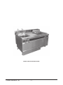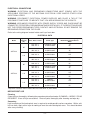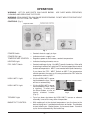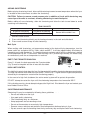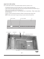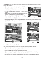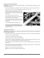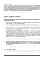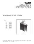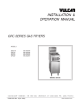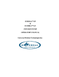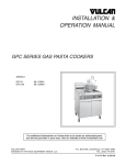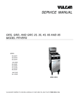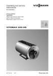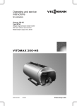
1
ELECTRIC FRYERS MODEL 3HFD140 ML-126831 4HFD140 ML-126832 701 S. RIDGE AVENUE TROY, OHIO 45374-0001 937 332-3000 www.hobartcorp.com FORM 34613 (Mar. 2001) MODEL 3HFD140 ELECTRIC FRYER HOBART CORPORATION, 2001 –2– Installation, Operation, and Care of Model 3HFD140 & 4HFD140 Electric Fryers SAVE THESE INSTRUCTIONS GENERAL The model 3HFD140 electric fryer has a unitized cabinet with one 85 lb. fry tank on the left, one 140 lb. fry tank on the right, and a 25" Frymate station positioned between the two fry tanks. Built-in underneath the left fry tank and the Frymate station is a filter unit plumbed to drain cooking oil from either the 85 lb. fry tank on the left or the 140 lb. fry tank on the right. The system filters the oil as it is pumped back to its respective tank. Valves inside the doors under each fry tank must be set so only one tank is being drained, filtered, and pumped back at any one time. The model 4HFD140 electric fryer has the same equipment as the 3HFD140 except it has a second 140 lb. fry tank on the extreme right side. Standard features include stainless steel (front and sides) and electronic solid state temperature controls with fat melt feature for each tank. The 85 lb. fry tank on the left side is provided with two basket lifts including an automatic timer for each basket. INSTALLATION Before installing, verify that the electrical service agrees with the specifications on the rating plate located on the inside of the fryer door panel. UNPACKING Immediately after unpacking, check for possible shipping damage. If the fryer is found to be damaged, save the packaging material and contact the carrier within 15 days of delivery. The following components are shipped separate from the fryer: Two Fry Baskets; One Crumb Screen for each Fry Tank; Filter Tank, Filters, and Lid, and the Oil Hose. LOCATION The fryer may be installed at 0" clearance from the back or side walls. INSTALLATION CODES AND STANDARDS The fryers must be installed in accordance with: 1) State and local codes; 2) The National Electrical Code, ANSI/NFPA No. 70 (latest edition), available from The National Fire Protection Association, Batterymarch Park, Quincy, MA 02269; and 3) NFPA Standard #96. LEVELING — LEGS or CASTERS Place a carpenter's level on top of the fryer and level the fryer front-to-back and side-to-side by turning the adjustable legs. To adjust a fryer equipped with casters, first determine which caster(s) must be adjusted. Then lift and block the fryer so it is adequately supported. Next, loosen the set screw on the shank of the caster(s) that need to be adjusted. Raise or lower the caster(s) as needed by turning the lower portion of the caster assembly; then re-tighten the set screws. Set the fryer back on the floor. Lock the front casters’ brakes during use. Caster equipped fryers must be provided with a restraint device attached to the juncture of the vertical and horizontal frame members at the rear to prevent strain on the connectors. Reconnect this restraint after any power disconnection before reconnecting the electrical power supply. –3– ELECTRICAL CONNECTIONS WARNING: ELECTRICAL AND GROUNDING CONNECTIONS MUST COMPLY WITH THE APPLICABLE PORTIONS OF THE NATIONAL ELECTRICAL CODE AND/OR OTHER LOCAL ELECTRICAL CODES. WARNING: DISCONNECT ELECTRICAL POWER SUPPLIES AND PLACE A TAG AT THE DISCONNECT SWITCHES TO INDICATE THAT YOU ARE WORKING ON THE CIRCUITS. WARNING: APPLIANCES EQUIPPED WITH POWER SUPPLY CORDS AND PLUGS MUST BE CONNECTED TO PROPERLY GROUNDED MATING RECEPTACLES. IF THE RECEPTACLES ARE NOT THE PROPER GROUNDING TYPES, CONTACT AN ELECTRICIAN. DO NOT REMOVE THE GROUNDING PRONG FROM THE PLUGS. Refer to the wiring diagram located inside each fryer front door. ELECTRICAL DATA Model Fry Tank Capacity (lb.) 85 3HFD140 140 85 4HFD140 140 140 Volts / Hertz / Phase Circuit Type Minimum Circuit Ampacity Maximum Protective Device AMPS 120 / 60 / 1 208 / 60 / 3 Controls & Pump 24 KW Heaters 15 80 120 / 60 / 1 480 / 60 / 3 Controls & Pump 24 KW Heaters 15 35 120 / 60 / 1 208 / 60 / 3 Controls 30 KW Heaters 15 125 120 / 60 / 1 480 / 60 / 3 Controls 36 KW Heaters 15 50 120 / 60 / 1 208 / 6 0 / 3 Controls & Pump 24 KW Heaters 15 80 120 / 60 / 1 480 / 60 / 3 Controls & Pump 24 KW Heaters 15 35 120 / 60 / 1 208 / 60 / 3 Controls 30 KW Heaters 15 125 120 / 60 / 1 480 / 6 0 / 3 Controls 36 KW Heaters 15 50 120 / 60 / 1 208 / 60 / 3 Controls 30 KW Heaters 15 125 120 / 6 0 / 1 480 / 60 / 3 Controls 36 KW Heaters 15 50 Compiled in accordance with the National Electrical Code, NFPA-70 (latest edition). BEFORE FIRST USE Cleaning Clean the fryer thoroughly, following the procedures described under CLEANING — WEEKLY OR AS REQUIRED. Clean all fryer accessories. Rinse all parts thoroughly after cleaning and wipe dry. Seasoning Light seasoning of the backsplash area is required to avoid possible surface corrosion. With a soft, lint-free cloth, apply a thin layer of cooking oil over the entire backsplash area. This should be done after every cleaning. –4– OPERATION WARNING: HOT OIL AND PARTS CAN CAUSE BURNS. CLEANING AND SERVICING THE FRYER. USE CARE WHEN OPERATING, WARNING: SPILLING HOT OIL CAN CAUSE SEVERE BURNS. DO NOT MOVE FRYER WITHOUT DRAINING THE OIL FROM THE TANKS. CONTROLS (Fig. 1) Fig. 1 POWER Switch — Controls electric supply to fryer. POWER ON Light — Indicates electric supply is on. TEMPERATURE CONTROL — Regulates power to the heaters, controls temperature. HEATING Light — Indicates heating elements are on. FRY / MELT Switch — Controls melting or frying. Use MELT to melt shortening. After solid shortening is melted, turn switch to FRY and set temperature control to desired temperature. MELT is not needed with liquid shortening. If you leave the FRY / MELT Switch on MELT, the temperature control operates the same as if it were positioned on FRY after the temperature reaches 135°F . HIGH LIMIT 1 Light HIGH LIMIT 2 Light — If lit, the HIGH LIMIT 1 sensor has shut down the fryer. Reset will occur automatically. — If lit, the HIGH LIMIT 2 sensor has shut down the fryer. Reset is required. To reset, push the Reset Button at rear of heater element header (Fig. 2). HEADER – HEATER ELEMENT RESET BUTTON PL-41521-1 Fig. 2 TROUBLE Light — Fryer has been shut down by HIGH LIMIT 2 sensor or element assembly is not all the way down into position. BASKETLIFT CONTROL — With cooking oil at the desired temperature, turn the timer to the desired frying time. Load basket and place on holder. Push button to start timed cycle. Basket lowers; cycle counts down. At end of cycle, device automatically lifts basket up. –5– ADDING SHORTENING Before placing shortening in tank, allow solid shortening to come to room temperature where the fryer is located for one to two hours to soften the shortening. CAUTION: Failure to remove crumb screens prior to addition of fresh solid shortening may cause fryer side walls to overheat, allowing shortening to reach flashpoint. Before adding all new shortening, drain old shortening and allow the tank to cool down to avoid scorching new shortening. TANK CAPACITY Fry Tank on Left Fry Tank on Right 85 pounds of shortening 140 pounds of shortening 10.76 gallon (40.76 liter) 17.73 gallon (67.13 liter) Maintain Proper Shortening Level Between MIN and MAX Lines 1. Remove crumb screen. 2. Place solid shortening directly on the heating elements in the tank and slide back. 3. Place crumb screen on top of solid shortening. Melt Cycle When melting solid shortening, set temperature control at the desired frying temperature, turn the power switch on, and place the FRY / MELT switch on MELT. It will take approximately 45 minutes to completely melt solid shortening. The heating elements cycle on and off until the shortening is melted and a temperature of 135°F is achieved. After reaching 135°F (shortening is melted), the heaters stay on continuously until the set temperature is reached. EMPTY THE FRYMATE DRAIN PAN DRAIN PAN Every 5 – 6 loads, the drain pan under the Frymate station (Fig. 3) must be emptied and the oil must be discarded. PL-41529-1 Fig. 3 HIGH LIMIT CONTROL The high limit control shuts down the fryer if a thermostat fails and the shortening becomes overheated. The high limit control shuts down the fryer at 435°F which is 60 F° higher than the highest temperature allowed by the temperature control when functioning properly. In the event of a high limit shutdown, the entire control system will be put out of operation. DO NOT attempt to restart the fryer until the shortening temperature has lowered to 350°F. If this situation persists, do not attempt to bypass the High Limit. Shut down the fryer and contact your local Hobart Service Office. SHORTENING MAINTENANCE Shortening life may be extended by following these guidelines . . . • • • • • • • Do not salt foods over the fryer. Use good quality shortening. Filter shortening daily at a minimum. Keep equipment and surroundings clean. Do not set thermostats at excessively high temperatures. Remove excess moisture and particles from food products before placing in fryer. Dip out several cups of shortening from the fry tank every day and replace with fresh shortening. –6– USING THE FILTER SYSTEM Filter system parts must be in their proper positions while the system is in use . . . • Crumb Basket hangs on left Tank Handle (Fig. 4) to catch crumbs during draining. • Filter must be flat on tank bottom and Filter Orifice must be placed over the tank hole (Fig. 4). • Elbow must be threaded into Tank Fitting (Fig. 4). • Lid must be in place over tank. Drain Opening is over Crumb Basket. Elbow extends above Suction Opening. • Drawer is closed so Suction Connector on Elbow is connected to the Suction Port. • NOTE: Make sure the two O-rings are always in place inside the Suction Port. DRAIN OPENING LEFT TANK HANDLE LID SUCTION OPENING CRUMB BASKET TANK FILTER FILTER ORIFICE UNDERNEATH SUCTION CONNECTOR ELBOW TANK FITTING PL-41522-1 Fig. 4 –7– WARNING: HOT OIL AND PARTS CAN CAUSE BURNS. USE CARE WHEN FILTERING. DO NOT LEAVE UNATTENDED. • Warm fryer compound to a temperature of 260°F before filtering. Turn fryer power switch off. • If desired, add 8 oz. of diatamaceous earth to the filter tank or add it to the fry tank with stirring. • To drain fry tank, position Drain Valve in OPEN position (Fig. 5). • Allow cooking oil to drain from the fry tank into the filter tank, catching any large particles in the Crumb Basket. DRAIN VALVE (OPEN) • Brush residue at bottom of Fry Tank into drain tube. Flush out bottom of Fry Tank by turning Filter Power Switch ON (Fig. 6) and pulling Filter Lever (Fig. 7) forward. PL-41523-1 Fig. 5 • After allowing cooking oil to flush out the bottom of the Fry Tank, return Drain Valve to CLOSED position (Fig. 8) and allow oil to refill Fry Tank. Observe FULL line on Fry Tank wall. When done, push Filter Lever (Fig. 7) to rear. DISCARD LEVER FILTER LEVER DISCARD FITTING PL-41523-2 Fig. 7 FILTER PUMP MOTOR RESET BUTTON DRAIN VALVE (CLOSED) FILTER POWER SWITCH PL-41526-1 PL-41524-1 Fig. 6 Fig. 8 Periodic Batch Cleaning of the Filter Tank After filtering several times, you should clean the Filter Tank when it is empty and cool . . . • Remove the Crumb Basket and empty any debris into the trash. • Remove the Filter and scrape any debris into the trash. • Clean any debris from the Filter Tank and put in the trash. • When necessary, thoroughly clean the Crumb Basket and the Filter before re-installing them. • Re-hang the Crumb Basket on the left handle of the Filter Tank. • Re-install the Filter flat on the tank bottom so the Filter Orifice is placed over the tank hole. –8– Flushing and Discarding Used Oil WARNING: HOT OIL AND PARTS CAN CAUSE BURNS. USE CARE WHEN FILTERING. DO NOT LEAVE UNATTENDED. • Warm fryer compound to a temperature of 260°F before filtering. Turn fryer power switch off. • Open Drain Valve (Fig. 5) and allow cooking oil to drain into Filter Tank. • Connect Hose to Discard Fitting. Push Hose Fitting onto the Discard Fitting and release the Collar so the Hose Fitting is locked on, tight (Figs. 6, 9). DISCARD LEVER COLLAR • Turn Filter Power Switch ON (Fig. 6). • While holding the Hose Handle securely, direct the nozzle into a suitable container. HOSE • Pull white Discard Lever forward (Fig. 9) to permit outflow. Push white Discard Lever back to stop flow. • Turn Filter Power Switch OFF when done. • Use care when disconnecting the Hose in case some hot oil is inside. Pull Hose Collar towards you to release coupling, and then pull hose off of Discard Fitting. PL-41525-1 Fig. 9 Cleaning the Filter System CAUTION: Do not pump water or water based cleaning solutions through the filter system to avoid damaging the pump. • Allow parts to cool. Pull the Filter Drawer out and remove the tank lid. The tank should be empty. • Lift the Filter Tank out of the drawer. • Lift the Drawer away from the Drawer Slides. • Lift the Drawer Slides up and off the Slide Guides. • Take the Filter Tank with Crumb Basket and Filter, the Drawer and Drawer slides to a sink or dishwasher for a thorough washing with detergent and warm water. • Disassemble the Filter by slideing the metal latch off the bar and lifting the bar up to access the internal filter. • Wash all the removed parts in normal dishwashing detergent and warm water. These parts may also be washed in a commercial dishwasher. • Replace all removed parts before operating fryer. • NOTE: All parts must be completely dry before reuse. –9– CLEANING — DAILY Clean your fryer regularly. If regular cleaning is neglected, grease will be burned on and discolorations may form. These may be removed by washing with detergent or soap and water. Particularly stubborn discolorations may be removed with a self-soaping scouring pad or a paste made of water and a mild scouring powder applied with a plastic open pad or sponge. Do not use standard steel wool on stainless steel finishes. Steel wool particles will adhere to the stainless steel and cause rusting. Always rub in the direction of the polish lines on the steel front to preserve the original finish. Keep the fryer exterior clean and free of accumulated grease to prevent stubborn stains. Wash exterior surfaces at least once daily. Wash with a cloth soaked in a solution of warm water and mild detergent. Rinse with clear water. Dry with a clean cloth. CLEANING — WEEKLY OR AS REQUIRED Fry Tank, Heating Elements, and Thermostat Bulb CAUTION: Do not pump water or water based cleaning solutions through the filter system to avoid damaging the pump. 1. Once the shortening has been drained, flush out scraps and sediment with a small amount of warm shortening. Allow the tank to drain thoroughly. 2. Remove all cooking oil from the filter tank by pumping it to suitable storage container(s) or discard old oil. Remove filter tank, crumb basket, filter, drawer and drawer slides (refer to page 9). 3. Close the Drain Valve (Fig. 8) and fill the tank with a solution of water and non-corrosive, grease dissolving commercial cleaner (boilout compound), diluted to the cleaner manufacturer’s instructions (refer to Tank Capacity, page 6). 4. Set the temperature control at a temperature recommended by the manufacturer of the commercial cleaner and boil the solution for 10 to 15 minutes. If cleaner is a water based chemical, temperature control may be set at 190 – 212°F. Set the temperature as low as possible; monitor boiling to prevent overflow. Do not leave fryer unattended. Turn Fryer Power Switch OFF and allow the solution to set in the fry tank for another 10 – 15 minutes. The tank may be scrubbed using a long handled brush. Do not use a metal brush or scouring pad to clean the fry tank interior. Avoid skin contact with hot water and caustic solution. 5. Use care when draining the cleaning solution from the fry tank into a suitable container — do not overfill the container. Close the drain valve and empty the container as often as necessary until the fry tank is empty. 6. Close the Drain Valve (Fig. 8) and refill the tank with clean hot (minimum 140°F) water. Add 1 cup of vinegar to neutralize alkaline left by the cleaner. Turn Fryer Power Switch ON and boil for a few minutes with the temperature control set at 190 – 212°F. Turn the Fryer Power Switch OFF when done. 7. Again, use care when draining the cleaning solution from the fry tank into a suitable container — do not overfill the container. Close the drain valve and empty the container as often as necessary until the fry tank and the container are empty. 8. Dry the fry tank thoroughly. 9. Close the drain valve and add shortening to a level between the MIN and MAX markings on the fryer tank wall. If using solid shortening, refer to Melt Cycle under Adding Shortening, page 6. – 10 – Stainless Steel Stainless steel may be cleaned with a solution of detergent and warm water. To prevent water spots and streaks, rinse equipment thoroughly with warm water and wipe dry with a clean cloth. The addition of a rinsing agent will also help prevent spotting. Fingerprints Fingerprints are sometimes a problem on highly polished surfaces of stainless steel. They can be minimized by applying a cleaner that will leave a thin, oily or waxy film. Wipe cleaner on and remove excess with a clean cloth. After using, subsequent fingerprints will usually disappear when wiped lightly with a clean cloth or with a cloth containing a little of the cleaner. If the surface is especially soiled, wash first with a cloth soaked in a solution of detergent and warm water. Burned On Foods and Grease Soaking with hot soapy water will help remove burned on foods and grease. Stubborn deposits can be removed with scouring powder mixed into a paste and applied with stainless steel wool or sponges. Always rub with the grain. Heat Tint Straw-colored or slightly darkened areas may appear on stainless steel equipment where temperatures reach 500°F or more. This ‘Heat Tint’ is caused by a slight oxidation of the stainless steel and is not harmful. To control this conditon, never use more heat than is necessary. Precautions When scraping off heavy deposits of grease or oil from stainless steel equipment, never use ordinary steel scrapers or knives. Particles of ordinary steel may become embedded in the surface of the stainless steel. These will rust, causing unsightly stains. Where necessary to scrape, use stainless steel, wood, plastic, or rubber tools, or stainless steel wool. – 11 – MAINTENANCE WARNING: HOT OIL AND PARTS CAN CAUSE BURNS. CLEANING, AND SERVICING THE FRYER. USE CARE WHEN OPERATING, WARNING: DISCONNECT ELECTRICAL POWER SUPPLIES BEFORE PERFORMING ANY MAINTENANCE. WARNING: SPILLING HOT OIL CAN CAUSE SEVERE BURNS. DO NOT MOVE FRYER WITHOUT DRAINING THE OIL FROM THE TANKS. CALIBRATION PROCEDURES 1. Monitor shortening temperature one inch below the surface with an accurate temperature measuring device. 2. Turn Fryer Power Switch ON, and when coming up from lower temperature, set temperature control knob to frying temperature. 3. Allow fryer to reach temperature (when heating light goes off) and maintain it (by cycling) for 15 minutes. 4. Check temperature when the heating light first comes on. If the reading is not within five degrees of the temperature control setting, take the following steps. A. Loosen the set screw on the temperature control knob. B. Rotate the knob and set the knob to read the same as the shortening temperature readings. C.Tighten the set screw on the temperature control knob. D. Allow the fryer to cycle and check the readings. E. If for any reason calibration is not obtained in this manner, call your local Hobart Service Office. LUBRICATION The filter motor is permanently lubricated and no lubrication is required. SERVICE Contact your local Hobart Service Office for any repairs or adjustments needed on this equipment. FORM 34613 (Mar. 2001) – 12 – PRINTED IN U.S.A.