1
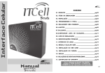
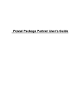
5.1 Amplifier Owner's Manual
Table of Contents
Important Safety Information ...............................................................................4
Introduction..........................................................................................................6
Description ...........................................................................................................6
Unpacking and Installation ...................................................................................7
Rear Panel Connections ........................................................................................8
Power Control Connections ..................................................................................9
Channel Configurations ......................................................................................11
System Connections ............................................................................................12
Input and Bridging Connections.........................................................................13
Speaker Wire Preparation and Connection..........................................................17
Operation............................................................................................................19
Service Information .............................................................................................20
Troubleshooting Guide........................................................................................21
Specifications.......................................................................................................22
Madrigal Audio Laboratories
2081 South Main Street, P.O. Box 781
Middletown, CT 06457 USA
Made in USA
©1995 Harman Kardon, Incorporated
3
Important Safety Information
Verify Line Voltage Before Use
Your new Citation 5.1 amplifier has been factory configured for a specific line voltage: 110-120 volts for North America or 220-240 volts in most other countries.
Connecting the amplifier to a line voltage other than that for which it is intended
can create a safety and fire hazard, and may damage the amplifier.
If you have any questions about the voltage requirements for your specific model,
or about the line voltage in your area, contact your Citation dealer before plugging
the unit into an AC wall outlet.
Verify AC Circuit Capacity Before Use
High power output of your Citation amplifier requires heavy current draw under
full load conditions. To insure proper performance, and to avoid potential safety
hazards, we recommend that it be connected to a circuit with 20 ampere capacity.
Connecting multiple amplifiers to the same circuit, or connecting it to a circuit
used by other heavy power devices such as high wattage lights may cause circuit
breakers to trip. It is always a good idea to avoid using any audio equipment on the
same AC circuit as equipment with motors, such as air conditioners or refrigerators. This will lessen the possibility of power variation and electrical start-up noise
affecting your sound system.
Do Not Use Extension Cords
To avoid safety hazards, use only the power cord supplied with your unit. If a replacement cord is used, make certain that it is of similar gauge. We do not recommend that
extension cords be used with this product. As with all electrical devices, do not run
power cords under rugs or carpets or place heavy objects on them. Damaged power
cords should be replaced immediately with cords meeting factory specifications.
Handle the AC Power Cord Gently
When disconnecting the power cord from an AC outlet, always pull the plug, never
pull the cord. If you do not intend to use the amplifier for any considerable length
of time, disconnect the plug from the AC outlet.
Do Not Open the Cabinet
There are no user serviceable components inside this product. Opening the cabinet
may present a shock hazard, and any modification to the product will void your
guarantee. If water or any metal object such as a paper clip, wire or a staple accidentally falls inside the unit, disconnect it from the AC power source immediately,
and consult an authorized service station.
4
Installation Location
• To assure proper operation, and to avoid the potential for safety hazards, place the
unit on a firm and level surface. When placing the unit on a shelf, be certain that
the shelf and any mounting hardware can support the amplifier. Remember, the
Citation 5.1 weighs over 60 pounds.
• High powered audio amplifiers such as the Citation 5.1 may develop moderate
amounts of heat. Therefore, if the unit is installed in a cabinet it is recommended
that the rear of the cabinet be left open to permit air circulation. If that is not
possible, ventilation holes should be placed at both the top and bottom of the
cabinet or enclosure, or at the sides, bottom and top. A minimum of six (6)
inches should be provided between each side of the unit and the cabinet, and at
least twelve (12) inches above and two (2) inches below the unit. In some cases a
fan may be required to provide for air movement within a cabinet. Please consult
your dealer or installer for more information.
• Do not place the unit directly on a carpeted surface.
• Avoid installation in extremely hot or cold locations, or in an area that is exposed
to direct sunlight or heating equipment.
• Avoid moist or humid locations.
• Do not obstruct the ventilation slots on the top of the unit, or place objects
directly over them.
• Speaker wiring, input cables and power cords should be carefully placed so that
they do not come in contact with, or intefere with the external heat sinks.
Cleaning
When the unit gets dirty, wipe it with a clean, soft, dry cloth. If necessary, first wipe
the surface with a soft cloth slightly dampened with mild soapy water, then a fresh
cloth with clean water. Wipe dry immediately with a dry cloth. NEVER use benzene,
thinner, alcohol or any other volatile cleaning agent. Do not use abrasive cleaners, as
they may damage the finish of metal parts. Avoid spraying insecticide near the unit.
Moving the Unit
Before moving the unit, remove any interconnect cords, and unplug it from the
AC outlet.
CAUTION
RISK OF ELECTRIC SHOCK
DO NOT OPEN
CAUTION: To prevent electric shock, do not remove the grounding plug on the power cord, or use any
plug or extension cord that does not have a grounding plug provided. Make certain that the AC outlet is
properly grounded. Do not use an adapter plug with this product.
The exclamation point within an equilateral
triangle is intended to alert the user to the
presence of important operating and maintenance (servicing) instructions in the literature accompanying the appliance.
The lightning flash with arrowhead symbol,
within an equilateral triangle, is intended to
alert the user to the presence of uninsulated
“dangerous voltage” within the product's
enclosure that may be of sufficient magnitude to constitute a risk of electric shock to persons.
5
Introduction
Congratulations! As the owner of a Citation 5.1 Multi Channel Power
Amplifier, you have at your command a unique product. The Citation 5.1 has been
carefully designed to deliver the best possible sonic performance, along with outstanding industrial design to match the rest of the Citation series, or to complement any interior design. Combining sculpted metal panels, the latest state of the
art circuit design, and Harman Kardon’s forty-year heritage of audio excellence, the
Citation 5.1 will bring many years of enjoyable listening to your music or home
theater system.
In order to fully enjoy the performance of your new amplifier, please take a few
minutes to read this manual. It contains important information that will help you
to properly configure the amplifier for use with the rest of your audio system. The
brief investment of time spent in reading this manual will yield major dividends in
the form of listening enjoyment.
If you have any questions about this product, its installation or operation, please
contact your retailer or custom installer. They are your best source of product information. Should you need additional information or assistance, the toll-free number
for the Citation Center is 800-787-6766.
Welcome to the Citation family. We wish you many years of listening pleasure!
5.1 Amplifier
Description
The Citation 5.1 is a flexible, state of the art audio power amplifier designed to
deliver high performance in a variety of applications. Each of the four amplification
channels has a separate power supply, which means that it delivers audiophile performance no matter which configuration is selected. You may operate the 5.1 in a
two, three or four-channel mode, and benefit from the following array of sophisticated features:
• Ultrawide bandwidth design
• Low negative feedback
• Fully complementary bipolar circuitry with over-designed output stage for
high reliability
• Low harmonic and intermodulation distortion
6
• Massive heat sinks for silent convection cooling
• High current power supply design with massive torrodial transformer
• Quad mono power supply
• New, linearized pre-driver stage circuit
• Remote turn on/turn off circuitry with automatic sequencing
Unpacking and Installation
The carton and shipping materials used in protecting your new amplifier were specially designed to cushion it from the shocks and vibration of shipping. We suggest
that you save the carton and packing materials for use in shipping if you move or
should the unit ever need repair.
To minimize the size of the carton in storage, you may wish to flatten it. This is
done by carefully slitting the tape seams on the bottom and collapsing the carton
down to a more two-dimensional appearance. Other cardboard inserts may be
stored in the same manner. Packing materials that cannot be collapsed should be
saved along with the carton in a plastic bag.
In order to assure a high level of performance and long life, the Citation 5.1 has
been engineered from robust materials. This weight, however, requires, that you
pay special attention to unpacking and installation of the unit. First, you may wish
to have someone help you remove the unit from its carton and place it in the proper location. In addition, when moving the amplifier, be careful not to set it down
on the heat sink edges to avoid damage to their surface or finish. Similarly, be careful to avoid scratching any contact surface with the heat sinks, as their edges may
be sharp.
Make certain that any shelf or stand is capable of supporting the weight of the
amplifier. This is particularly true if you will be stacking multiple amplifiers on the
same shelf.
When positioning the amplifier in its final location, make certain that it has adequate ventilation on all sides, as well as on the top and bottom. Do not place CDs,
record jackets, owner’s manuals, or other paper, on top of, or beneath the unit, or
between multiple amplifiers in a stack. This will block air flow, causing degraded
performance and a possible fire hazard. If the unit is to be enclosed in a cabinet or
rack, make certain that there is adequate air circulation, with a means provided for
hot air to exit, and for cool air to be brought in. In some instances, a fan may be
required for this purpose. If you are in doubt as to the ventilation requirements,
please consult with your dealer or installer.
When stacking multiple Citation 5.1 amplifiers in a rack or cabinet, place the unit
which will power front and/or center channel speakers at the bottom of the stack.
Next, place the amplifier used for surround speakers in the center. The unit which
will be used to power subwoofers should be at the top of the stack.
7
Rear Panel Connections
Bridged/Normal Switches: These switches control the output configuration of a pair of channels.
Switch them down for normal use. Switch them down to “bridged” to combine amplifier channels for
higher power output. See page 13 for more information on channel configuration and bridging.
Power Switch: This is the master AC power
switch for the unit. See page 19 for more
information.
Remote In: This is the input jack for remote
turn on control of the 5.1. Connect it to a
Citation Controller, and another Citation
amplifier or other approved devices.
See page 9 for more information.
Manual/Remote Switch: The switch controls
the power turn on of the 5.1. When switched up
and in the “manual” position, power is turned
on or off by the rear panel switch. When
switched down to the “remote” position, power
is controlled by signals from the Citation 7.0
controller or some other device. See page 9
for more information.
NORMAL
Remote Out: This is the output jack used
to carry control signals for remote turn on
of additional Citation amplifiers in your
system. See page 9 for more information.
NORMAL
MANUAL
TURN ON
MODE
MODE
OFF
5.1 Multi-Channel
Power Amplifier
ON
CH 2 INPUT
REMOTE
TURN ON
DC
OUT
REMOTE
+
–
+
BRIDGED
CH 4 INPUT
(NOT USED IN
BRIDGED MODE)
–
BRIDGED
+
+
+
BRIDGED
MODE
CH 3 INPUT
(BRIDGED INPUT)
(NOT USED IN
BRIDGED MODE)
+
Citation,a division of
Harman Kardon,
Hayward, CA.
BRIDGED
MODE
CH 1 INPUT
(BRIDGED INPUT)
DESIGNED & MANUFACTURED
IN THE USA.
DC
IN
SERIAL NUMBER
~
120V
50/60Hz
1200 WATTS
–
CH 1 OUTPUT
–
–
–
BRIDGED
BRIDGED
CH 3 OUTPUT
CH 2 OUTPUT
CH 4 OUTPUT
WHEN USING THESE CHANNELS IN BRIDGED MODE,
USE THE CH 3 INPUT AND CONNECT THE SPEAKER TO
THE RED TERMINALS AS DIAGRAMMED ABOVE.
WHEN USING THESE CHANNELS IN BRIDGED MODE,
USE THE CH 1 INPUT AND CONNECT THE SPEAKER TO
THE RED TERMINALS AS DIAGRAMMED ABOVE.
WARNING: TO REDUCE THE RISK OF FIRE OR
CAUTION
ELECTRIC SHOCK DO NOT EXPOSE THIS EQUIPMENT TO
RAIN OR MOISTURE. DO NOT REMOVE COVER. NO USERSERVICEABLE PARTS INSIDE. REFER SERVICING TO
QUALIFIED SERVICE PERSONNEL.
RISK OF ELECTRIC SHOCK
DO NOT OPEN
AVIS: RISQUE DE CHOC ELECTRIQUE - NE PAS OUVRIR
Power Cord Connector:
Connect the AC power cord here.
Audio Input Connections: See page 13
for information on proper connections
and input configurations.
Speaker Connection Binding Posts: Connect the
wire running to your speakers to these binding posts.
See page 11 for information on channel configurations
connections. See page 17 for information on connecting
speaker wire to the terminals.
8
Power Control Connections
The Citation 5.1 amplifier features a built-in system that will automatically turn
on the amplifier when another device in the system is switched on. To activate this
system, the 5.1 must be used in conjunction with a Citation Surround Controller
or Processor, other Citation Power Amplifiers, and other approved devices.
Remote Turn On With a Citation Controller or
External Trigger Control Device
The first connection is to link your amplifier to the controlling device. Connect the
“PWR” Trigger output at the rear of a Citation Processor or an approved control
device to the “Remote DC IN” connection on the rear panel of your 5.1. Make
certain that the controlling device sends a 4.5 VDC to 12 VDC signal whenever it
is turned on. If you are using a Citation 7.0 Controller, be certain to use the
“PWR” control trigger, not one of the numbered programmable trigger outputs.
Citation 7.0 Controller
7.0 AV Controller
IN 1
IN 2
IN 3
AUX
OUT
IN 4
MAIN
OUT
Additionally licensed under U.S. patent numbers 5,172,415; 5,263,087; 5,199,075; 5,307,415; 5,280,528; 5,339,363; 5,295,189; 4,932,059; and patents pending.
CAUTION
RISK OF ELECTRIC SHOCK
DO NOT OPEN
SERIAL
NUMBER
IN 5
IN 6
IN 7
IN 8
REC A
OUT
REC B
OUT
IN 1
IN 2
IN 3
COMPOSITE VIDEO
2
3
4
IN 4
REC A
OUT
REC B
OUT
AUX
OUT
AVIS: RISQUE DE CHOC ELECTRIQUE - NE PAS OUVRIR
AUX
OUT
WARNING: TO REDUCE THE RISK OF FIRE OR
S – VIDEO
ELECTRIC SHOCK DO NOT EXPOSE THIS EQUIPMENT TO
RAIN OR MOISTURE. DO NOT REMOVE COVER. NO USERSERVICEABLE PARTS INSIDE. REFER SERVICING TO
QUALIFIED SERVICE PERSONNEL.
AUDIO OUTPUTS
AUDIO INPUTS
1
POWER
Manufactured under license from Dolby Laboratories Licensing Corporation. Additionally licensed under Canadian patent number 1,037,877. "Dolby", "Pro Logic" and the
Double-D symbol are trademarks of Dolby Laboratories Licensing Corporation.
Manufactured under license from Lucasfilm Ltd. U.S. patent numbers 5,043,970; 5,189,703; abd 5,222,059. Foreign patents pending. Lucasfilm and THX are registered
trademarks of Lucasfilm Ltd.
A division of
Hayward, CA.
Designed and Manufactured in the USA.
5
6
7
REC A
OUT
8
REC B
OUT
FRONT
CENTER
FRONT
SURROUNDS
SIDE
BACK
STEREO
SUB
120V
L
L
L
L
R
R
R
R
CALIBRATION
MICROPHONE
MONO
SUB
1
2
PWR
~ 50/60Hz
50 WATTS
IR
IN
TRIGGERS
CITATION BUS
Citation 5.1 Amplifier
NORMAL
MODE
Optional
Accessory
Switch
Control
NORMAL
MODE
MANUAL
TURN ON
OFF
ON
REMOTE
BRIDGED
CH 1 INPUT
CH 2 INPUT
TURN ON
MODE
(BRIDGED INPUT)
(NOT USED IN
BRIDGED MODE)
+
+
–
BRIDGED
–
DC
DC
IN
OUT
REMOTE
BRIDGED
CH 3 INPUT
CH 4 INPUT
MODE
(BRIDGED INPUT)
(NOT USED IN
BRIDGED MODE)
+
+
–
–
BRIDGED
CH 1 OUTPUT
+
–
BRIDGED
AC/DC
Converter
+
–
BRIDGED
CH 2 OUTPUT
CH 3 OUTPUT
CH 4 OUTPUT
Optional Remote Trigger Devices
Citation 5.1 Amplifier
NORMAL
MODE
MANUAL
TURN ON
CH 1 INPUT BRIDGED CH 2 INPUT
(BRIDGED INPUT) MODE (NOT USED IN
BRIDGED MODE)
REMOTE
TURN ON
NORMAL
MODE
OFF
ON
+
+
–
BRIDGED
–
DC
DC
IN
OUT
REMOTE
BRIDGED
CH 3 INPUT
CH 4 INPUT
MODE
(BRIDGED INPUT)
(NOT USED IN
BRIDGED MODE)
+
+
–
–
–
BRIDGED
CH 2 OUTPUT
OFF
–
CH 3 OUTPUT
MANUAL
TURN ON
+
BRIDGED
BRIDGED
CH 1 OUTPUT
+
CH 4 OUTPUT
ON
REMOTE
TURN ON
DC
DC
IN
OUT
REMOTE
Citation 5.1 Amplifier
NORMAL
MODE
NORMAL
MODE
Figure 1a
BRIDGED
CH 3 INPUT
CH 4 INPUT
MODE
(BRIDGED INPUT)
(NOT USED IN
BRIDGED MODE)
Exploded View of Critical
Rear Panel Area
MANUAL
TURN ON
OFF
ON
REMOTE
BRIDGED
CH 1 INPUT
CH 2 INPUT
TURN ON
MODE
(BRIDGED INPUT)
(NOT USED IN
BRIDGED MODE)
+
+
–
BRIDGED
–
BRIDGED
CH 1 OUTPUT
CH 2 OUTPUT
DC
DC
IN
OUT
REMOTE
+
+
–
–
+
–
BRIDGED
+
–
BRIDGED
CH 3 OUTPUT
CH 4 OUTPUT
Figure 1 Remote Turn On Connections
9
If this is the only remote controlled amplifier in the system, no further connections
are needed. If multiple remote controlled amplifiers are used, connect the “Remote
DC OUT” jack on one amplifier to the “Remote DC IN” on the next unit in the
system.
Finally, make certain that the “manual/remote” switch on the rear panel is in the
“remote” position to activate the remote control circuits.
If the amplifier is to be controlled manually, the toggle switch should be in the
“manual” position, and power will be switched on and off using the master power
switch on the rear panel.
Remote Turn On Using External AC to DC Power Converter
If the 5.1 is not used with a compatible Citation Controller/Processor or other
approved external device that is capable of generating turn on control voltages,
it is still possible to activate the unit for automatic turn on.
To control the amplifier in this fashion you will need a small AC to DC power
converter, capable of delivering a 4.5 to 12 volts DC signal at 100 milliamperes.
The DC voltage should terminate in a standard mini plug with the positive voltage
going to the tip and the negative voltage going to the ring. This type of converter
may be obtained at Radio Shack stores as catalog #273-11454.
Plug the AC adapter into a switched outlet that will be activated when you wish to
have the amplifier(s) turn on. This may be the switched outlet at the rear of an AC
receiver or other audio equipment, an AC outlet that is part of a current sensing
control unit that is activated by a preamp or surround processor, or a switched AC
wall outlet.
The DC output jack should be connected to the “DC IN” jack on the rear of
the 5.1 amplifier. If there are additional amplifiers in the system, they may be
connected by running a cable from the “DC OUT” jack on the first amplifier
to the “DC IN” jack on the second, and so on.
Before turning on the amplifiers, be certain that the “manual/remote” switch on
the rear panel is in the “remote” position.
The amplifiers will now turn on in sequence when power is applied to the AC outlet where the converter is plugged in. The first unit will turn on, and then each successive unit will come on following a short pause.
10
Channel Configurations
The Citation 5.1 may be used in a variety of configurations. Consult your
dealer or installer for advice on which may be best for your system and listening
requirements.
Four-Channel Operation
In multi-channel use such as a home theater system, the four channels may be
allocated in a variety of ways. In some applications, they will be used to drive the
left, center and right channel front speakers, with the fourth channel devoted to
a subwoofer. Although you may wish to power each subwoofer with a separate,
or even bridged amplifier channel, the exceptional power supply capability of
the 5.1 will also permit you to power the three front speakers as well as a pair
of subwoofers, provided that they are no less than 6 ohms each and they are
connected in parallel.
For systems using Citation or Fosgate•Audionics brand Dual Drive™ surround
dipole speakers, the 5.1 may be used to power all four rear channels with a single
amplifier.
Three-Channel Operation
For installations where higher power is desired for a center channel speaker, the
5.1 may be operated in a three-channel mode. Left and right front channel feeds
are run through two unbridged channels, while the center channel is operated in
a bridged mode. This allows the greater output demands of a center channel to
be met, while still delivering power with headroom to spare for the left and right
channels.
In systems with conventional surround speakers, a three-channel application may
be to feed the two rear channels in an unbridged mode, while the remaining two
amplifier channels are bridged together to power a subwoofer.
Two-Channel Operation
The immense power capability of the Citation 5.1 allows it to be used in a dual
bridged mode as a conventional stereo amplifier. For critical music listening, this
will permit you to drive virtually any full range speaker in the largest home acoustical and physical space, delivering classic two-channel stereo sound at its finest.
For home theater applications, the Citation 5.1 may be operated in a dual-bridged
mode to power two subwoofers in large room-size installations.
Caution: When used in the dual-bridged mode, the Citation 5.1 is capable of
very high peak current outputs. Please make certain that your speakers are capable of handling this level of power before using the amplifier in this mode.
11
System Connections
Note: When making connections between any source components or proces-
sors or preamplifiers and the Citation 5.1, or when making any connections to
speakers, be certain that both the input device and the amplifier are turned off.
To assure that there will be no unwanted signal transients that can damage
equipment or speakers, it is always best to unplug all equipment before making
any connections. Modern electronic products often have a “standby” mode that
may be activated even though the product may appear to be turned off.
As a general rule, avoid running any input signal or speaker wire connections in
parallel with each other, or with AC power cords. This can result in undesired hum
or other interference that will greatly degrade signal performance.
When making connections with “RCA” type plugs on interconnect cables, make
certain to gently, but firmly insert the plug into the jack on the back of the Citation
5.1. Loose connections can cause intermittent sound and may damage your speakers. The barrel assembly of some high quality RCA plugs may be very tight, and it
is important to assure a proper connection between the interconnection cable and
the input jack.
12
Input and Bridging Connections
The RCA jacks and bridging switches on the unit’s rear panel are used to connect
your surround processor or preamplifier to the amplifier, as well as to select the
channel configuration. Once you have determined what the channel configuration
will be, connect the output of your system to the amplifier as follows:
Citation 7.0 Controller
7.0 AV Controller
IN 1
IN 2
IN 3
AUX
OUT
IN 4
MAIN
OUT
Additionally licensed under U.S. patent numbers 5,172,415; 5,263,087; 5,199,075; 5,307,415; 5,280,528; 5,339,363; 5,295,189; 4,932,059; and patents pending.
CAUTION
RISK OF ELECTRIC SHOCK
DO NOT OPEN
SERIAL
NUMBER
IN 5
IN 6
IN 7
IN 8
REC A
OUT
REC B
OUT
IN 1
IN 2
IN 3
COMPOSITE VIDEO
2
3
4
IN 4
REC A
OUT
REC B
OUT
AUX
OUT
AVIS: RISQUE DE CHOC ELECTRIQUE - NE PAS OUVRIR
AUX
OUT
WARNING: TO REDUCE THE RISK OF FIRE OR
S – VIDEO
ELECTRIC SHOCK DO NOT EXPOSE THIS EQUIPMENT TO
RAIN OR MOISTURE. DO NOT REMOVE COVER. NO USERSERVICEABLE PARTS INSIDE. REFER SERVICING TO
QUALIFIED SERVICE PERSONNEL.
AUDIO OUTPUTS
AUDIO INPUTS
1
POWER
Manufactured under license from Dolby Laboratories Licensing Corporation. Additionally licensed under Canadian patent number 1,037,877. "Dolby", "Pro Logic" and the
Double-D symbol are trademarks of Dolby Laboratories Licensing Corporation.
Manufactured under license from Lucasfilm Ltd. U.S. patent numbers 5,043,970; 5,189,703; abd 5,222,059. Foreign patents pending. Lucasfilm and THX are registered
trademarks of Lucasfilm Ltd.
A division of
Hayward, CA.
Designed and Manufactured in the USA.
5
6
7
REC A
OUT
8
REC B
OUT
FRONT
CENTER
FRONT
SURROUNDS
SIDE
BACK
STEREO
SUB
120V
L
L
L
L
R
R
R
R
CALIBRATION
MICROPHONE
MONO
SUB
NORMAL
MODE
1
2
PWR
TRIGGERS
Note: Both switches
NORMAL
MODE
OFF
REMOTE
BRIDGED
CH 1 INPUT
CH 2 INPUT
TURN ON
MODE
(BRIDGED INPUT)
(NOT USED IN
BRIDGED MODE)
+
+
–
BRIDGED
–
DC
DC
IN
OUT
REMOTE
+
–
–
+
–
+
BRIDGED
–
BRIDGED
BRIDGED
Citation 5.1 CH 1 OUTPUT
Amplifier
should be in “Bridged”
position – this is Twochannel operation mode.
A jumper is used to
connect both pairs of
negative (“-”) terminals.
BRIDGED
CH 3 INPUT
CH 4 INPUT
MODE
(BRIDGED INPUT)
(NOT USED IN
BRIDGED MODE)
+
CH 2 OUTPUT
50 WATTS
CITATION BUS
MANUAL
TURN ON
ON
~ 50/60Hz
IR
IN
CH 3 OUTPUT
CH 4 OUTPUT
Subwoofer
Speakers
–
NORMAL
MODE
–
+
+
Note: Switch between
NORMAL
MODE
MANUAL
TURN ON
Ch. 1 & Ch. 2 should
be in “Normal” position .
Switch between Ch. 3
& Ch. 4 is in “Bridged”
position – this is Threechannel mode. A jumper
is used to connect the
Ch. 3 & Ch. 4 speaker
negative (“-”) terminals.
OFF
ON
REMOTE
BRIDGED
CH 1 INPUT
CH 2 INPUT
TURN ON
MODE
(BRIDGED INPUT)
(NOT USED IN
BRIDGED MODE)
+
+
–
BRIDGED
–
DC
DC
IN
OUT
REMOTE
BRIDGED
CH 3 INPUT
CH 4 INPUT
MODE
(BRIDGED INPUT)
(NOT USED IN
BRIDGED MODE)
+
+
–
–
+
CH 1 OUTPUT
+
–
BRIDGED
Citation 5.1
Amplifier
–
BRIDGED
BRIDGED
CH 2 OUTPUT
CH 3 OUTPUT
CH 4 OUTPUT
Front Channel
Speakers
–
+
–
NORMAL
MODE
+
–
Note: Both switches
NORMAL
MODE
MANUAL
TURN ON
OFF
ON
REMOTE
BRIDGED
CH 1 INPUT
CH 2 INPUT
TURN ON
MODE
(BRIDGED INPUT)
(NOT USED IN
BRIDGED MODE)
+
+
–
BRIDGED
–
DC
DC
IN
OUT
REMOTE
BRIDGED
CH 3 INPUT
CH 4 INPUT
MODE
(BRIDGED INPUT)
(NOT USED IN
BRIDGED MODE)
+
+
–
–
+
Single Drive
Dipole
4Ω
Dual Drive
8Ω /ch.
CH 2 OUTPUT
–
CH 3 OUTPUT
Single Drive
Point Source
4Ω
Single Drive/Side Input
Back Input
CAUTION: Please refer to owner's manual
before making any electrical connection
to this speaker.
+
BRIDGED
BRIDGED
Citation 5.1 CH 1 OUTPUT
Amplifier
–
BRIDGED
Single Drive
Dipole
4Ω
Citation
Dual Drive™
Dipoles
Dual Drive
8Ω /ch.
CH 4 OUTPUT
Single Drive
Point Source
4Ω
Single Drive/Side Input
Back Input
CAUTION: Please refer to owner's manual
before making any electrical connection
to this speaker.
Figure 2 System Connections
13
+
should be in the “Normal”
position – this is Fourchannel operation.
Four-Channel Operation:
Using high quality interconnect cables, connect one output of your processor to an
amplifier input channel. There is no special priority as to which specific channel
(i.e. left, right, center, etc.) is connected to which amplifier channel when all four
channels are used individually. You need only remember what the channel is, so
that the proper speaker may be connected to the correct output.
Make certain that both bridging switches are in the “normal” position. The toggle
switches should be pointing up for both inputs.
Connect the wire running to each speaker to the appropriate output channel as
shown on the speaker icons to the right or left of the speaker connection binding
posts. (Figure 2A) The “+” or “positive” connection goes to the top binding post
with the red barrel. The “-” or “negative” connection goes to the bottom binding
post with the black barrel.
TO PROCESSOR
NORMAL
MODE
NORMAL
MODE
MANUAL
TURN ON
OFF
ON
REMOTE
BRIDGED
CH 1 INPUT
CH 2 INPUT
TURN ON
MODE
(BRIDGED INPUT)
(NOT USED IN
BRIDGED MODE)
+
+
DC
DC
IN
OUT
REMOTE
–
BRIDGED
–
BRIDGED
CH 3 INPUT
CH 4 INPUT
MODE
(BRIDGED INPUT)
(NOT USED IN
BRIDGED MODE)
+
+
–
–
+
—
BRIDGED
CH 2 OUTPUT
Single Drive/Side Input
+
Back Input
+
–
BRIDGED
CH 1 OUTPUT
–
BRIDGED
CH 3 OUTPUT
Note: Both
Bridge/Normal
switches should point
Up to the “Normal”
position.
CH 4 OUTPUT
Single Drive/Side Input
—
+
Back Input
Figure 2A Four-Channel Operation with Dual Drive Dipoles
Three-Channel Operation:
When one high-powered channel and two medium-powered channels are required,
the three-channel mode is used. Using high quality interconnect cables, link the
output of your processor or preamplifier for the moderate powered channels
(left/right front or surround channels) to the input connectors marked “Channel
One” and “Channel Two”. Be certain that the bridging switch on the left side of
the rear panel, above the inputs for Channel One and Channel Two, is in the
“Normal” position with the toggle switch pointing up.
Connect the output from your processor or preamp which is to be connected to
the higher powered amplification channel (center or subwoofer channels) to the
input connector marked “Channel Three” on the rear of the Citation 5.1. The
input connection for “Channel Four” is not used in this configuration. (Figure 2B)
14
TO PROCESSOR
NORMAL
MODE
NORMAL
MODE
MANUAL
TURN ON
OFF
ON
REMOTE
BRIDGED
CH 1 INPUT
CH 2 INPUT
TURN ON
MODE
(BRIDGED INPUT)
(NOT USED IN
BRIDGED MODE)
+
+
–
BRIDGED
–
DC
DC
IN
OUT
REMOTE
BRIDGED
CH 3 INPUT
CH 4 INPUT
MODE
(BRIDGED INPUT)
(NOT USED IN
BRIDGED MODE)
+
+
–
–
+
+
–
BRIDGED
CH 1 OUTPUT
–
BRIDGED
BRIDGED
CH 2 OUTPUT
CH 3 OUTPUT
CH 4 OUTPUT
Speakers
–
+
–
+
–
+
Note: Switch on left (ch. 1 & ch. 2) is in the “Up” or “Normal” position.
Switch on the right (ch. 3 & ch. 4) is in the “Down” or “Bridged” position.
Figure 2B Three-Channel Operation
To bridge the two channels, put the switch between the two input connectors in
the “Bridged” position with the toggle switch pointing down.
In this configuration, connections to the speakers receiving the normal power feed
from the unbridged channels should be made to the connectors for Channels One
and Two in the normal fashion. That is, connect the wire running to each speaker
to the appropriate output channel as marked. The “+” or “positive” connection
goes to the top binding post with the red barrel. The “-” or “negative” connection
goes to the bottom binding post with the black barrel.
The connection for the higher power, (bridged) channel should be following the
connection diagram between the speaker connection binding posts for Channel
Three and Four. Connect the “+” or positive connection going to the binding post
marked “+” for Channel Three to the “+” or “red” terminal on the speaker. The
connection going to the negative terminal on the speaker should be connected to
the binding post marked “+” for Channel Four. (Figure 2B)
To complete the bridging of the circuits, use one of the jumpers packed with the
5.1 to make a connection between the Negative (“-”) speaker connection terminals
for Channel 3 and Channel 4 as shown in Figure 2B.
WARNING: The jumper connection should not be made when the amplifier is
turned on. This connection must be made before operating the amplifier in a
bridged mode.
Two-Channel Operation:
In this mode two high-powered channels are provided for subwoofer use, or for
high-powered conventional stereo applications. Using high quality interconnect
cables, connect one output from your preamp or processor to the input connector
marked “Channel One”, and the other to the input connector marked “Channel
Three”. The input connectors for channels Two and Four are not used in this configuration. (Figure 2C)
15
TO PROCESSOR
NORMAL
MODE
NORMAL
MODE
MANUAL
TURN ON
OFF
ON
REMOTE
BRIDGED
CH 1 INPUT
CH 2 INPUT
TURN ON
MODE
(BRIDGED INPUT)
(NOT USED IN
BRIDGED MODE)
+
+
–
BRIDGED
–
DC
DC
IN
OUT
REMOTE
BRIDGED
CH 3 INPUT
CH 4 INPUT
MODE
(BRIDGED INPUT)
(NOT USED IN
BRIDGED MODE)
+
+
–
–
BRIDGED
CH 1 OUTPUT
+
–
+
BRIDGED
–
BRIDGED
CH 2 OUTPUT
CH 3 OUTPUT
CH 4 OUTPUT
Speakers
–
+
–
+
Note: Both switches should point Down to the “Bridged” position.
Figure 2C Two-Channel Operation
For two-channel use, make certain that BOTH bridging switches are engaged by
switching them down, to the “bridged” position.
In the bridged mode, the connections to your speakers should be made using only
the top row of binding post connections. Follow the connection diagram that is
between the speaker connections. For the speaker connected to the Channel One
input, connect the “+” terminal of the Channel One output to the wire going
to the “+” or red colored connection on your speaker. Connect the “+” terminal
of the Channel Two output to the wire going to the “-” or black terminal of
your speaker.
Repeat this procedure so that the input signal connected to the Channel Three
input connector is connected to your speaker using the “+” speaker output connector of Channel Three as the “+” or “red” wire, and the “+” speaker output
connector of Channel Four as the “-” or “black” wire.
To complete the bridging of the circuits, use the jumpers packed with the 5.1 to
make a connection between the Negative (“-”) speaker connection terminals for
Channel 1/Channel 2, and Channel 3/Channel 4 as shown in Figure 2C.
WARNING: The jumper connections should not be made when the amplifier
is turned on. This connection must be made before operating the amplifier in
a bridged mode.
Note: When using the 5.1 in a dual-bridged configuration, particularly with
4 ohm speaker loads, it will probably be necessary to provide additional cooling
using a small fan. This cooling will also be needed in the dual-bridged mode if
the amplifier is enclosed in a cabinet. Consult your dealer or custom installer for
more information.
16
Speaker Wire Preparation and Connection
Once the proper hookup has been selected using the previous section, make the
physical connection using the following instructions.
Cables or Connecting Wire
To assure that the high quality signals produced by your Citation amplifier are carried to your speakers without loss of clarity or resolution, we recommend that you
use high quality speaker cable. Many brands of cable are available, and the choice
of cable may be influenced by the distance between your speakers and the amplifier,
the type of speakers you use, personal preferences, and other factors. Your dealer
or installer is a valuable resource to consult in selecting the proper cable for
connections between your amplifier and speakers.
Regardless of the brand or type of cable selected, we recommend that you use a
cable constructed of fine, multi-strand copper with a AWG of 14 or larger.
Remember, that in specifying cable, the lower the number, the thicker the cable.
Cable with an AWG of 16 may be used for short runs of less than ten feet. We do
not recommend that you use any cables with an AWG equivalent of 18 or higher
due to the power loss and degradation in performance that will occur.
One way to insure that cables will deliver a predictable level of performance is to
use cables that are Home THX® certified. This certification assures that the cables
have met a rigorous set of specifications designed for home theater applications.
Cables that are run inside walls should have the appropriate markings to indicate
listing with UL, CSA or other testing agency standards. Questions about cables
inside walls should be referred to your installer or a licensed electrical contractor
who is familiar with the NEC and/or the applicable local building codes in
your area.
Connections to Speakers
Regardless of the channel configuration used, the final step of the installation
process is to connect the amplifier to your speakers, using high quality cable, as
outlined above. A pair of binding posts is provided for each channel output. These
posts will accept bare wire, spade lugs or banana-type plugs where permitted by
local safety agencies.
If bare wire is used for the connections, strip approximately 1/2 inch to 3/4 inch
(20mm) of insulation from the end of each wire and carefully twist the strands of
each conductor together. Be careful not to cut the individual strands or twist them
off; for optimal performance, all strands must be used.
Then, loosen the knobs of the speaker output terminals, far enough so that the
pass-through hole is revealed. Note that one conductor of the speaker cable may
have no markings, and the other will have a red line, brand name markings, a black
thread, or some other positive indication. Follow the proper connection instructions for your system with regard to which terminals are used. The small speaker
17
icons next to each pair of terminal posts will guide you to the correct connections.
When the connections are made, twist the cap back so that the connection is
secured, but do not overtighten or use tools, as this may break the delicate wire
strands and decrease system performance. Also, make certain that the wire strands
connected to one terminal do not contact the other terminal or wires. This will
result in a short circuit.
If you are using spade lugs, connect them to the wire using the manufacturer’s
instructions, and then loosen the caps on the speaker terminals. Place lugs between
the plastic cap and the back of the terminal, as if it were a horseshoe on the game’s
post. Be sure to observe proper polarity, using the appropriate speaker hookup
icons for your system’s configuration. Tighten with your fingers to obtain a
positive contact.
When banana plugs are permitted, connections may be made by simply inserting
the jack affixed to your speaker wire into the hole provided on the rear of the colored screw caps on the binding posts. Before using banana-type jacks, make certain
that the plastic screw caps are firmly tightened down by turning them in a counterclockwise direction until they are snug against the chassis. This will insure that the
maximum surface area of the plug is in contact with the jack. Be certain to observe
proper polarity.
Finally, run the cables to the speaker locations. It is highly recommended that the
length of cable connecting any pair of speakers is identical. For example, make certain that the cable length connecting left and right front, or left and right rear (surround) speakers are identical, even though one speaker may be physically closer to
the amplifier than the other. Do not coil any excess cable, as this may become an
inductor that creates frequency response variations in your system.
Finally, connect the wires to the speakers, again being certain to observe proper
polarity. Remember to connect your “negative” or “black” wire to the matching terminal on the speaker. Similarly, the “positive” or “Red” wire should be connected
to the like terminal on the speaker.
Note: While most speaker manufacturers adhere to an industry convention of
using black terminals for negative and red ones for positive, some manufacturers
may vary from this configuration. To assure proper phase connections, and optimal performance, consult the identification plate on your speaker terminals, or
the speaker’s manual to verify polarity. If you do not know the polarity of your
speaker, ask your dealer or installer for advice before proceeding, or consult the
speaker’s manufacturer.
18
Operation
Operation of the Citation 5.1 is simple. There are no controls to adjust once the
installation is complete.
After all connections have been made to the amplifier’s inputs and speaker terminals, connect the AC power cord to the socket on the rear panel. Make certain that
the master power switch on the rear panel is in the OFF position. Connect the
power cord to an AC outlet.
Note that it is not recommended that you connect multiple 5.1 Amplifiers to the
same AC power circuit unless they are used with the remote power turn on and
sequencing system. The simultaneous turn on of multiple amplifiers on the same
circuit may cause circuit breakers to trip.
Note: Do not attempt to defeat the grounding plug on the power cord. This
will cause a safety hazard. It will also increase the chance of unwanted hum
appearing in your system. If a properly grounded AC outlet is not available,
contact your installer or a licensed electrician for assistance.
At this point you are ready for listening: First, turn on the source components and
processor in your system. It is always a good idea to turn on your amplifier LAST.
This avoids the possibility of any turn on pops or transients from other equipment
being amplified and sent to your speakers where they may cause damage. Always
start with a low volume level on your controller or preamp to avoid damage to your
speakers.
For Manual Operation:
If the unit is not being used with the automatic, remote turn on system, place the
“manual/remote” toggle switch in the “manual” position. Switch the rear panel
master power switch to the ON position. The LED below the Citation name on
the front panel will illuminate and turn blue to let you know that power is applied.
There will be a short pause between the time the power is turned on until power
is applied to the speakers. This is intentional, and it protects your speakers from
damage as the amplifier stabilizes. You may also hear a relay click as during
start-up. This is also normal.
You are now ready to enjoy the finest sonic performance available. All volume and
level adjustments are made at your preamp, controller or surround processor.
To turn the unit off, switch the rear panel master power switch to the OFF
position.
19
For Automatic Operation:
Make certain that all connections to the Citation Controller or Processor, and to
any other Citation power amplifiers in the system have been correctly made as
shown on pages 13 through 16. Switch the “manual/remote” toggle switch on the
rear panel to the “remote” position. Turn the master power switch ON, position.
The LED below the Citation name will turn amber to indicate that the unit is in
the “standby” mode with AC power applied.
Your Citation 5.1 amplifier will now turn on automatically whenever the processor or
controller is switched on. You may verify that your amplifier has been turned on in
response to the control signal by noting that the LED below the Citation name will
change from amber to blue. There will be a short second pause between the time the
signal is applied and the indicator changes color until power is applied to the speakers. This pause is intentional, and it protects your speakers from damage as the amplifier stabilizes. You may also hear a relay click as during start-up. This is also normal.
Once your system is turned on, you are ready to enjoy the finest sonic performance
available. There are no controls to adjust on the Citation 5.1 amplifier. All volume
and level adjustments are made by your preamp, controller or surround processor.
There is no need to turn the amplifiers off manually. Simply turn off the Citation
Controller or Processor, or the device providing the automatic control voltages and
the 5.1 amplifier will go into a standby mode. Turn off and return to a standby
mode may be confirmed by noting that the LED indicator under the Citation
name on the front panel turns from blue to amber.
Important Note: If you will not be using your audio system for an extended
period of time, such as a vacation, it is always a good idea to turn the unit off
using the rear panel power switch. This will prevent the automatic turn on circuits from accidentally turning the system on during your absence.
Service Information
If your installation has followed the suggestions in this manual you should enjoy
many years of trouble-free operation and high quality listening enjoyment. If you
suspect a problem that may require service assistance, contact your dealer, installer
or an authorized Citation Service Depot. The Citation 5.1 does not contain any
user serviceable parts. In the event of a problem, contact your dealer, custom
installer or Madrigal Technical Services at 888-691-4171 (USA Only).
It is important that any repairs be carried out only by an authorized Citation service agent to assure proper service and to preserve the protection of your Limited
Warranty. It is a good idea to keep your sales slip or receipt in a safe place with this
manual so that it will be available to verify the purchase date for warranty claims.
Fuse
The Citation 5.1 uses internal fuses to protect both it and your speakers from damage. In the event that a fuse replacement is required, make certain that a fuse of the
original rating is used. Contact an authorized Citation service agent for assistance
with fuse replacement.
20
Input/Output Protection
Under some conditions, such as a shorted speaker wire, DC voltage on an input
connection or thermal overload, the Citation 5.1 will place itself in a “protect”
mode to prevent damage to your speakers. When this happens the power indicator
will turn red and no signal will be heard. You may hear a relay “click” on as the
unit goes into its protection mode.
When this occurs, turn the unit off using the rear panel switch, and correct the
problem. Turn the unit back on. If the unit continues to go into a protect mode,
contact your dealer or installer for assistance.
Troubleshooting Guide
The Citation 5.1 is designed for trouble free operation. In normal use, most users
will not encounter any problems with the unit. However, as with any sophisticated
electronic device, there may be occasional problems on initial installation, or
during the life of the unit. The items on this list are a brief guide to the minor
problems that you may be able to correct yourself. If these solutions do not rectify
a problem, or if the problem persists, contact your dealer, installer or an authorized
Citation service center for assistance.
Problem
Diagnosis
Troubleshooting Hints
Amplifier will not turn on. Master Power Switch Turned Turn on Master Power
Off. (No Power Light LED) Switch.
Make certain power cord
is firmly inserted into
receptacle.
Remote turn-on system not Check all connections and
properly configured.
switch settings for remote
(Power Light LED is amber) system.
Check External Trigger
Device.
Amplifier turns on, but
Inputs not connected to
Check Input Connections.
no audio from one or
proper jack.
more channels.
Speakers not connected
Check Speaker Connections.
properly.
Improper settings or output Check the settings on your
levels from the processor or preamp, processor or
controller.
controller.
Audio plays, then cuts off.
Amplifier Shorted
(LED is red)
Check Speaker connections
for short circuit.
21
Page
8, 19
8
8, 9
9
11-16
13-18
Consult the
manual for
the source
device.
13-18
Specifications
Power Output:
4 x 100 watts @ 8 ohms, 4 x 175 watts @ 4 ohms
2 x 100 watts + 1 x 300 watts @ 8 ohms,
2 x 300 watts @ 8 ohms bridged
FTC: 20 - 20 kHz, .03% THD, All channels driven
HCC:
100 Amps/channel in dual mono mode
Frequency Response:
<3 Hz - 200 kHz ±3 dB at rated output
THD/IMD:
Less than 0.03% at rated output
Power Bandwidth:
5 Hz - 130 kHz
Input Impedance:
22K Ohms
Input Sensitivity:
1.1 volt for rated output
Control Trigger Voltage:
3.5 - 12 volts DC at 100 milliamperes
Dimensions (HxWxD):
5-7/8 x 17-5/16 x 16-1/8 inches
149 x 440 x 410 mm
Weight:
60 lbs/27.3 kg
Power Requirements:
120VAC, 50 Hz - 60 Hz
1800 watts, maximum
Dual Drive is a trademark of Harman Kardon, Inc.
Dolby and Pro Logic are registered trademarks of Dolby Laboratories Licensing Corp.
THX is a registered trademark of Lucasfiilm Ltd.
All features and specifiications are subject to change without notice.
22
Staple or clip original invoice here. ▼
Madrigal Audio Laboratories
2081 South Main Street, P.O. Box 871
Middletown, CT 06457 USA
Telephone: 860.346.0896
Fax: 860.346.1540
Part No. CIT5.1OM