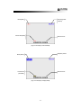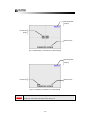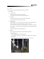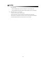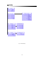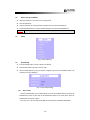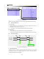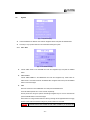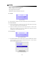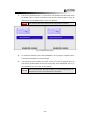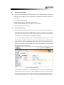
1
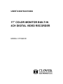
USER’S INSTRUCTIONS
17” COLOR MONITOR BUILT-IN
4CH DIGITAL VIDEO RECORDER
MODEL C1704DVR
CONTENTS:
1.
System Specifications-------------------------------------------------------------------------------------------
4
2.
How to operate --------------------------------------------------------------------------------------------------
6
2.1.
General Information ------------------------------------------------------------------------------------
6
2.2.
Configuration of the front panel of the unit
----------------------------------------------------
6
2.3.
Configuration of the back panel of the unit
----------------------------------------------------
7
2.4.
Basic configuration of the monitor display
----------------------------------------------------
8
2.5.
Live
---------------------------------------------------------------------------------------------------------
11
2.6.
Recording ------------------------------------------------------------------------------------------------
13
2.7.
Replaying -------------------------------------------------------------------------------------------------
14
Setup -----------------------------------------------------------------------------------------------------------
17
3.1.
Setup displays tree -----------------------------------------------------------------------------------
17
3.2.
How to set up [Model Number] -------------------------------------------------------------------
19
3.3.
Setup -------------------------------------------------------------------------------------------------------
19
3.4.
Alarm Setup ---------------------------------------------------------------------------------------------
19
3.
3.5.
3.6.
3.7.
3.4.1.
Alarm On/Off ------------------------------------------------------------------------------------
19
3.4.2.
Alarm Hold & Buzzer Out -------------------------------------------------------------------
20
3.4.3.
Post-Alarm Recording -----------------------------------------------------------------------
20
System ----------------------------------------------------------------------------------------------------
21
3.5.1.
Time / Date ---------------------------------------------------------------------------------------
21
3.5.2.
Hard Disk -----------------------------------------------------------------------------------------
22
3.5.3.
System Information ---------------------------------------------------------------------------
24
3.5.4.
Factory Default ---------------------------------------------------------------------------------
24
3.5.5.
Network IP Configuration -------------------------------------------------------------------
26
3.5.6.
DDNS ----------------------------------------------------------------------------------------------
27
3.5.7.
Log Information --------------------------------------------------------------------------------
29
Video --------------------------------------------------------------------------------------------------------
30
3.6.1.
Camera Titles -----------------------------------------------------------------------------------
30
3.6.2.
Dwell Time ----------------------------------------------------------------------------------------
30
3.6.3.
Brightness ----------------------------------------------------------------------------------------
31
3.6.4.
Contrast -------------------------------------------------------------------------------------------
31
Audio -------------------------------------------------------------------------------------------------------
32
3.7.1.
Audio Record ------------------------------------------------------------------------------------
32
3.7.2
Audio Replay ------------------------------------------------------------------------------------
32
-1-
Audio Level --------------------------------------------------------------------------------------
32
Record -----------------------------------------------------------------------------------------------------
33
3.7.4
3.8.
3.9
3.10
4.
5.
3.8.1
Overwrite -----------------------------------------------------------------------------------------
33
3.8.2
Power On Rec -----------------------------------------------------------------------------------
33
3.8.3
Record ---------------------------------------------------------------------------------------------
33
3.8.4
Record Quality ----------------------------------------------------------------------------------
34
3.8.5
IDSM* Sensitivity -------------------------------------------------------------------------------
34
3.8.6
Motion Sensitivity -----------------------------------------------------------------------------
34
3.8.7
Motion Hold --------------------------------------------------------------------------------------
35
3.8.8
Record Speed -----------------------------------------------------------------------------------
36
3.8.9
Record Schedule -------------------------------------------------------------------------------
36
Display ------------------------------------------------------------------------------------------------------
36
3.9.1
Various Displays -------------------------------------------------------------------------------
36
3.9.2
Border Line --------------------------------------------------------------------------------------
37
3.9.3
IDSM Display ------------------------------------------------------------------------------------
37
3.9.4
Monitor Display ---------------------------------------------------------------------------------
37
Account ----------------------------------------------------------------------------------------------------
38
3.10.1
Device ID & User ID ---------------------------------------------------------------------------
38
3.10.2
Password Setup --------------------------------------------------------------------------------
38
Networking --------------------------------------------------------------------------------------------------------
40
4.1
Requirement ----------------------------------------------------------------------------------------------
40
4.2
Installing the program to the PC -------------------------------------------------------------------
40
4.3
Cable Connection ---------------------------------------------------------------------------------------
40
4.4
Connection and Setting ------------------------------------------------------------------------------
41
4.4.1
IP Sharing Router Setup ---------------------------------------------------------------------
41
4.4.2
DvrAdmin Setup --------------------------------------------------------------------------------
42
How to use DvrAdmin -----------------------------------------------------------------------------------------
43
5.1
Connect -----------------------------------------------------------------------------------------------------
43
5.2
Live and Playback ---------------------------------------------------------------------------------------
43
5.3
5.4
5.2.1
Live Mode -----------------------------------------------------------------------------------------
43
5.2.2
Playback ---------------------------------------------------------------------------------------------
43
Save ----------------------------------------------------------------------------------------------------------
45
5.3.1
Still Image Save (BMP File Save) -----------------------------------------------------------
45
5.3.2
Video File Save (AVI File Save) --------------------------------------------------------------
46
Function of the buttons -------------------------------------------------------------------------------
47
5.4.1
INFO Button -------------------------------------------------------------------------------------
-2-
47
5.4.2
PRINT Button ------------------------------------------------------------------------------------
47
5.4.3
System Status -----------------------------------------------------------------------------------
48
5.4.4
Alarm, SEQ, OSD and Quad ----------------------------------------------------------------
48
5.4.5
Channel Selection Button -------------------------------------------------------------------
49
5.4.6
REC, SEARCH, STOP (ESC) and SETUP (ENTER) Button --------------------------
49
6.
Camera Installation --------------------------------------------------------------------------------------------
50
7.
Monitor and VCR Installation -------------------------------------------------------------------------------
51
8.
Remote Control -------------------------------------------------------------------------------------------------
52
APPENDIX -------------------------------------------------------------------------------------------------------------------
53
1.
Recording Time Table -----------------------------------------------------------------------------------------
53
2.
Factory Default Table ------------------------------------------------------------------------------------------
54
3.
FAQ ------------------------------------------------------------------------------------------------------------------
57
LIMITED 2 YEAR WARRANTY ------------------------------------------------------------------------------------------
59
HOW TO OBTAIN FACTORY SERVICE-------------------------------------------------------------------------------
59
-3-
1.
Specifications
DVR
Video Signal System
NTSC or PAL (Auto Detection)
Video Input
4 Camera Inputs (BNC or Mini Din)
Video Output
2 BNC Video Output for Slave Monitor or VCR
Audio Input
4 Channel (Mini Din or RCA)
Audio Output
2 Channel (VCR OUT / MONITOR OUT)
Alarm Input
4 Alarm Inputs
Alarm Related
Alarm Output
1 Alarm Output
Features
Post Alarm Recording
YES (Up to 30 seconds)
Video Loss Detection
YES
Display Size
720X480 (NTSC); 720X576 (PAL)
Video Display
Full, Quad for live and playback
Sequencing
YES
Recording Resolution
360X240 (NTSC); 360X256 (PAL)
Recording Rate
120 Frames per second (NTSC), 100 Frames per second (PAL)
Basic Features
Display Features
1~30 KB (Very High: 30 KB, High: 20 KB, Mid: 15 KB, Low: 10KB)
Image Size
* Calculated image size is without IDSM function. With IDSM setting,
the image size may be dramatically reduced.
Video Compression
MJPEG, Pseudo MPEG
Recording Mode
Continuous, Time-lapsed Recording, Schedule or Event Recording
Replay Format
1 Channel or Quad
Record and
Playback
Features
120 Frames per second at 360X240 (NTSC)
Playback Rate
100 Frames per second at 360X256 (PAL)
Playback Search
By date/time or event
Play Speed
x1 ~ x8192
Motion Detect Support
YES
Multiplex Recording
YES
Storage
Hard Disk Storage
3.5" IDE Type, Hot-swappable
and Backup
Backup
BMP & AVI File format through GUI
Ethernet
RJ45 Connector for network communication
RS-232
9-PIN female connector
Setup
On screen display setup
User Interface
Menu driven
Hardware
User Control
-4-
User Input Device
Front Panel keypad
Timer
Built-in real time clock
[Fig 1-1. Specifications]
MONITOR
Monitor
Picture Tube
17” Color Quad Screen
Horizontal Resolution
420 Line at Center
Camera Capable
Up to 4
Input Signal
Composite 1 Vp-p (V:0.714 Vp-p, Sync : 0.3 Vp-p)
Power Consumption
105 Watts (Max.)
AC Input
100 ~ 240 Volts 50 / 60 Hz
Dimensions
16.5’(W) X 16.5’(L) X 16.2’(H)
Weight
42 Lbs
Image Sensor
1/3” Color CCD, 270,000 pixels
Horizontal Resolution
330 TV Lines
Electronic Shutter Speed
NTSC: 1/60 to 1/100,000 sec, PAL: 1/50 to 100,000 sec
Input Signal
Composite 1 Vp-p (V:0.714 Vp-p, Sync : 0.3 Vp-p)
Lens
4.0mm C-mount for Indoor use, 4.0mm fixed lens for outdoor use
BLC, AWB & AGC
Automatic Adjustment
Housing
Metal structure
CAMERA
Monitor
[Fig 1-1. Specifications]
Specifications are subject to change without notice.
-5-
2.
How to operate
2.1
General Information
You can operate all functions of the system by use of the 18 buttons on the front of the unit. Additionally,
you can remotely control this unit via the Ethernet port located on the back side.
The system status is indicated by either with the LED light on the operator buttons or on the monitor.
The system does not record when it is in SETUP mode or REPLAY mode.
The system has the following 4 operating modes;
1. LIVE Mode
2. RECORD Mode
3. REPLAY Mode
4. SETUP Mode
2.2
Configuration of the front panel of the unit
11
2
1
3
17
4
5
19
18
6
7
21
20
8
9
10
13
12
23
22
15
14
25
16
26 27
24
[Fig. 2-1 Configuration of the front panel of the unit]
1) Removable HDD Rack
15) POWER LED (Power Status Display LED)
2) Ch1 (Channel Selection)
16) Monitor Power Switch
3) Ch2 (Channel Selection)
17) REC (Recording)
4) Ch3 (Channel Selection)
18) PLAY
5) Ch4 (Channel Selection)
19) STOP/ESC (Play Stop or Escape)
6) QUAD (Quad selection) / SEQ (Sequential Display)
20) SETUP/ENTER (System setup mode / Execution)
7) FREEZE (Freeze)
21) REW/LEFT (Rewinding / Navigation)
8) OSD (OSD On/Off)
22) PAUSE/RIGHT (Reverse Playback Pause / Navigation)
9) TALK** (Talk to specific camera)
23) PAUSE/DOWN (Playback Pause / Navigation)
10) REC LED (Recording Status Display LED)
24) FF/UP (Fast Forward / Navigation)
11) PLAY LED (Playback Status Display LED)
25) JOG SHUTTLE
-6-
12) TIMER LED (Timer Recording Status Display LED)
26) MIC
13) ALARM LED (Alarm Status Display LED)
27) REMOTE CONTROL SENSOR
14) HDD FULL LED (HDD Status Display LED)
** By pressing and holding this button the user has the ability to talk to a specific camera location.
This button must be pressed the entire time, while talking. To listen to the camera location, release
the Talk button.
2.3
Configuration of the back panel of the unit
1
3
VIDEO INPUT
4
9
8
CH1
CH2
CH3
CH4
10
5
AUDIO INPUT
1
2
3
4
GND
WARNING OUT
TRIGGER OUT
+
RS-485
VIDEO
AUDIO
VIDEO
VCR OUT
AUDIO
ETHERNET
MONITOR OUT
2
6
7
1) POWER S/W
Used to turn the system ON or OFF.
2) AC INPUT
Connects to a Power Plug (AC100-240V, 50/60Hz).
3) Mini Din Camera Inputs
Channel 1-4 Camera inputs (for cameras with 6 Pin DIN camera outputs)
4) BNC Camera Inputs
Channel 1-8 camera inputs (for cameras with BNC Video outputs)
5) RCA Audio Inputs
Channel 1-4 Audio inputs (for cameras with RCA Audio outputs)
6) Alarm Function Terminal
These terminals are used to connect external motion sensors.
7) RS-485 Terminal
Not available on this version
8) VCR A/V out
Audio/Video Out signal for transmitting to a VCR.
9) Monitor A/V out
Audio/Video Out signal for transmitting to a Slave Monitor.
10) Ethernet Port
Available to live view and recorded data on the HDD through the Internet or a LAN.
-7-
2.4
Basic configuration of the monitor display
Mode
Remaining HDD
Capacity
Camera Title
Date and Time
[Fig. 2-2 Quad Display in Record Mode (4 equal split)]
Playback position
Mode
Camera Title
Date and Time
[Fig. 2-3 Quad Display in Replay Mode (4 equal split)]
-8-
Mode (RED)
Remaining HDD
Capacity
Camera Title (RED)
Date and Time
[Fig. 2-4 Full Display in Record Mode]
Playback position
Mode (BLUE)
Camera Title
Date and Time
(ORANGE)
[Fig. 2-5 Full Display in Replay Mode]
-9-
Remaining HDD
Capacity
Camera Title
(white)
Date and Time
[Fig. 2-6 Quad Display in Live Mode, Not in Record Mode]
Remaining HDD
Capacity
Camera Title
Date and Time
[Fig. 2-7 Full Display in Live Mode, Not in Record Mode]
When the user turns off the recording, the REC display on top left corner will be
CAUTION
disappeared. And camera name will be shown as Fig. 2-6.
- 10 -
2.5
Live
Live means viewing the present video images from the cameras on the screen.
LIVE MODE
►
Full screen display
Full display is possible in the Live mode or Record mode.
Use channel selection button to choose a corresponding video input.
►
Quad display
All 4 cameras are viewed on the monitor at the same time in reduced size.
Quad display is available in Live mode or Record mode.
►
Sequential display
Sequential display is to set sequencing period when automatic screen sequencing mode is
selected in real time live mode. The sequential display is possible in Live mode.
Press the SEQ button. Default value for Sequential display is 2 seconds and the maximum
interval value is 7 seconds. Refer to chapter 3.6 Video Setup (SETUP>VIDEO>DWELL TIME)
for more details.
Press the button again to switch off the sequential mode.
►
FREEZE
Freeze is available in Live mode but only works when the DVR is not recording.
In the Full screen mode
- Press the FREEZE button to freeze the current display.
- Press the FREEZE button again or press another channel selection button to release the
Freeze function.
- When the FREEZE button is pressed, FREEZE mark will be shown on the screen.
Freeze Mark
- 11 -
In the Quad mode
- When the FREEZE button is pressed, all 4 displays are in freeze standby mode.
- Press the FREEZE button again to release the freeze standby function of all the displays.
►
OSD ON/OFF (OSD: On Screen Display)
- Available in LIVE, RECORD, or REPLAY Mode.
- When the OSD button is pressed, all the texts are cleared from screen temporarily.
- When the button is pressed again while OSD is in OFF, the system status will be displayed.
- Pressing the OSD button again will bring the system to normal condition.
- 12 -
2.6
Recording
Recording Option
►
Manual recording
►
Timer recording
►
Alarm recording
- Available in LIVE or RECORD mode
Manual recording
►
Recording will start when the REC button is pressed. The REC indicator will be lit and ‘REC’ will
blink on the screen while the unit is recording.
►
Press the REC button again to stop recording. The REC light will go off and ‘REC’ display on the
monitor will disappear. Color of camera title will turn to white once recording stops.
►
When the recording is manually started, the recording will continue until the REC button is
pressed again.
►
SETUP, PLAY and STOP buttons will be disabled during the recording.
Schedule recording
►
Recording by scheduled time
- The time of record start and finish can be set to hour : minute.
- Refer to chapter 3. Setup (SETUP>RECORD>RECORD SCHEDULE) for more details.
ALARM recording
►
When an alarm signal is received and ALARM ON recording is on, the system begins to record.
►
When the alarm signal is stopped, the system continues recording for the POST ALARM time
and finishes the recording.
- 13 -
2.7
Replaying
Replay Mode (Press PLAY button)
►
Replaying from the first recording time
►
Replaying from the last recording time
►
Replaying from the set recording time.
►
Replaying by event log lists.
Replaying from the first recording time
►
When the PLAY button is pressed, the SEARCH menu appears on the screen.
►
Select GO TO FIRST and press the ENTER button to start playback from the first recording time.
►
Press the ESC button to return to the SEARCH menu.
Replaying from the last recording time
►
When the PLAY button is pressed, the SEARCH menu appears on the screen.
►
Select GO TO LAST and press the ENTER button to start playback from the last recording time.
►
Press the ESC button to return to the SEARCH menu.
Replaying from the set recording time
►
When the PLAY button is pressed, the SEARCH menu appears on the screen as shown below.
[Fig. 2-8 SEARCH MENU]
- 14 -
►
Press DOWN button and select TIME & SEARCH menu. Press ENTER to select TIME &
SEARCH menu. TIME & SEARCH menu appears on the screen.
Replay Start
Record Start
Record Finish
[Fig. 2-9 TIME & SEARCH MENU]
►
THE FIRST RECORDED INFO displays beginning of the recording start time. THE LAST
RECORDED INFO displays end of the recording finish time.
►
The REPLAY TIME shows the recording end time.
►
Press the ESC button twice to return to LIVE mode.
►
Setting REPLAY TIME
- Select REPLAY TIME SETUP by pressing up/down keys and press ENTER button.
- Set the time by using the navigation keys: use the up/down keys for changing the values, the
left/right keys for moving to next fields.
- The REPLAY TIME can not be out of the RECORDED INFO time range.
Replaying by event log lists.
►
When the PLAY button is pressed, the SEARCH menu appears. Press the DOWN button and
select EVENT SEARCH menu. Press ENTER to select EVENT SEARCH menu.
►
Choose a LIST by pressing UP or DOWN button.
►
Press the ENTER button to start playback.
Replaying
►
Pause - Press the PLAY button to pause. Press it again to replay.
►
REW/FF
- During replaying, press the
button for fast rewinding, the
button for fast forwarding.
- Repeat pressing the REW or the FF button to accelerate the speed up to 8,192 times.
►
PREV/NEXT
- During replay, press the
button to view the previous frame in still image, press the
button to view the next frame in still image.
- Keep pressing the
or
button for continuous viewing.
- To play at normal speed again, press PLAY button.
- 15 -
Screen selection in Replaying
►
During replay, press the 1, 2, 3 or 4 button (channel selection button) to view only the
corresponding video channel.
►
Press the QUAD button to view the quad display.
►
The OSD ON/OFF button functions during replaying as well.
- 16 -
3.
Setup
3.1
Setup displays tree
- 17 -
[Fig. 3-1 Setup Displays]
- 18 -
3.2
How to set up C1704DVR
Setup is possible only in live mode, not in recording mode
Press the SETUP key
Choose a setup item by using the up/down navigation keys and press the ENTER key
Choose the desired value by using the right/left navigation keys and press the ENTER key
CAUTION
3.3
User must press the ENTER button to save the changes.
Setup
[Fig. 3-2 Setup Display]
3.4
Alarm Setup
Press the SETUP button on the front panel of C1704DVR.
Press the ESC button to go back to the live mode.
Choose ALARM SETUP by using the up/down navigation keys and press the ENTER button. The
following menu will be displayed.
[Fig. 3-3 Alarm Setup Display]
3.4.1
Alarm On/Off
- Choose ALARM ON/OFF in the ALARM SETUP menu with the navigation buttons and press the
ENTER button. Select an alarm and use the RIGHT/LEFT button to turn off the alarm. Press the
ENTER button to save the changes.
- If the alarm is on, user can select the ALARM ON recording option in RECORD SCHEDULE.
- 19 -
[Fig. 3-4 Alarm On/Off Display]
- ALARM ON: The system will record when the alarm activates. Select ALRAM ON for alarm recording.
3.4.2
►
Alarm Hold & Buzzer Out
ALARM HOLD
Choose ALARM HOLD in the ALARM SETUP menu with the navigation keys and use the
RIGHT/LEFT navigation buttons to change the time.
- Sec (second: 1- 20): The signal of alarm starts and stops between specific time.
►
BUZZER OUT
Choose BUZZER OUT in the ALARM SETUP menu and press the ENTER button.
Choose ON or OFF using the navigation keys and press the ENTER button to save the changes.
3.4.3
Post-Alarm Recording
Start
End
Start
End
Alarm Event
Recording
Post-Alarm Recording
[Fig. 3-5 Alarm Recording Options]
►
Post-Alarm Recording
Post-Alarm recording is to record for a selected time after the alarm deactivation. Up to 30 seconds
can be selected. This option is only available when the alarm is turned on. Select POST-ALARM in
the RECORD SCHEDULE when the alarm is on.
- 20 -
3.5
System
[Fig. 3-6 System Display]
Choose SYSTEM in the SETUP menu with the navigation buttons and press the ENTER button.
This setup is very important and has to be made before starting the system.
3.5.1
Time / Date
[Fig. 3-7 Time/Date Display]
►
Choose TIME / DATE in the SYSTEM menu with the navigation keys and press the ENTER
button.
►
TIME FORMAT
Choose TIME FORMAT in the TIME/DATE menu with the navigation keys. Select either 12
HOUR mode or 24 HOUR mode with the RIGHT/LEFT navigation buttons and press the ENTER
button to save the changes.
►
TIME
Enter the correct time in the TIME/DATE menu and press the ENTER button.
The three fields represent hour: minute: second, respectively.
Set the present time using the up/down and left/right navigation keys to move to next field and
press the ENTER button to save the changes.
Select APPLY to change the date and time. Warning message will be appeared before changing
the time. *User must know that time change may cause a data loss in the HDD.
CAUTION
The DVR uses the time and date to index video on HDD for you to search and
- 21 -
view the images later. Changing time and date can cause the DVR to work
improperly when you try to playback video.
Care should be taken not to change the time after the initial setup unless
absolutely necessary, as it may result in loss of recorded data. The HDD has to
be formatted after changing the time.
►
DATE FORMAT
Choose DATE FORMAT in the TIME/DATE menu with the navigation keys. Select the date
format between DD-MM-YYYY, YYYY-MM-DD and MM-DD-YYYY with the RIGHT/LEFT
navigation buttons and press the ENTER button to save the changes.
►
DATE
Choose the correct DATE in the TIME/DATE menu and press the ENTER button.
The three fields represent DD-MM-YYYY, YYYY-MM-DD or MM-DD-YYYY depends on user’s
selection of date format.
Set the present date using the up/down and left/right navigation keys to move to next field and
press the ENTER button to save the changes.
3.5.2
Hard Disk
[Fig. 3-8 Hard Disk Menu]
►
HDD FORMAT
Choose HDD FORMAT in the HARD DISK menu with the navigation keys. Press ENTER button
for formatting or press ESC button to go back to the previous mode.
[Fig. 3-9 HDD Formatting Process 1]
- 22 -
[Fig. 3-10 HDD Formatting Process 2]
[Fig. 3-11 HDD Formatting Process 3]
Press the ESC button to return after formatting is completed.
►
HDD INFO
Choose HDD INFO in the HARD DISK menu with the navigation keys and press ENTER button.
[Fig. 3-12 HDD Information Display]
- Model: Display model name and its model number (WDC-Western Digital, Maxtor-Maxtor)
- Serial: Display serial number of HDD.
- Total: Display the total capacity of HDD available for video storage in GB.
- Used: Display the amount of HDD used.
- 23 -
Be sure that the jumper setting is master position on the HDD. If not, the system
will not recognize the HDD. Format it to record (See page 22 for more details).
3.5.3
System Information
[Fig. 3-13 System Information Display]
► Choose SYSTEM INFO in the SYSTEM menu with the navigation keys and press ENTER button.
3.5.4
►
Factory Default
Choose FACTORY DEFAULT in the SYSTEM menu with the navigation keys and press ENTER
button to setup the system default or press ESC button to go back to the previous mode.
[Fig. 3-14 Factory Default Process 1]
[Fig. 3-15 Factory Default Process 2]
- 24 -
[Fig. 3-16 Factory Default Process 3]
[Fig. 3-17 Factory Default Process 4]
►
Press the ESC button to return after FACTORU DEFAULT is completed.
CAUTION
User must aware that FACTORY DEFAULT deletes all system logs.
- 25 -
3.5.5
Network IP Configuration
[Fig. 3-18 Network IP Configuration Setup]
Choose NETWORK IP CONFIG in the SYSTEM menu with the navigation keys and press
ENTER button.
Choose IP SETUP in the NETWORK IP CONFIG menu with the navigation keys and press
ENTER button.
[Fig. 3-19 IP Setup]
►
IP
Choose IP in the IP SETUP menu with navigation keys and press the ENTER button.
STATIC IP
Set the value using the navigation keys: UP/DOWN keys for changing the value and
LEFT/RIGHT keys for changing the position. Press ENTER to save the changes.
Choose APPLY and press ENTER button to apply the network setting to the system.
The gateway address, subnet mask and the IP address have to be set.
DYNAMIC IP
Choose DHCP and select ENABLE by pressing LEFT/RIGHT keys. Press ENTER to save the
changes.
Choose APPLY and press ENTER button to apply the network setting to the system.
When the DVR obtains the IP address, write down the IP address. It will be required for IP
Forwarding on Router setting.
- 26 -
►
GATEWAY / SUBNETMASK
Choose the item and press the ENTER button.
Set the value using the navigation keys: UP/DOWN keys for changing the value and
LEFT/RIGHT keys for changing the position. Press ENTER to save the changes.
►
PORT
The PORT is the TCP address of the program which is used to connect to the network viewer
and has a range of 2500 ~ 2509.
Choose PORT and press RIGHT/LEFT to change the value. Press ENTER to save the changes.
►
MAC ADDRESS
The MAC ADDRESS was consigned to each DVR unit at the factory.
User may use DDNS service instead of using dynamic IP. Dynamic IP changes each
time when the user turns on the system.
CAUTION
Write down the IP, PORT and PASSWORD. These are needed for network software
setup (GUI).
3.5.6
DDNS
[Fig. 3-20 DDNS Setup]
Choose ID / PASSWORD in the DDNS SETUP menu with the navigation keys and press
ENTER button. Set the value using the navigation keys: UP/DOWN keys for changing the value
and LEFT/RIGHT keys for changing the position. Press ENTER to save the changes.
►
WHAT IS DDNS?
DDNS provides a static domain name to those who have high-speed connection or use leased
lines with a dynamic Internet Protocol address. A dynamic IP address resolves the problem
stemming from the limited number of IP addresses. A dynamic IP address is given to users of
high-speed networks service and cable modems. Recently, even businesses that connect to the
web through leased lines use DHCP due to depletion of IP addresses. Almost all the PCs have a
dynamic IP address, which means that their IP address changes every time users turn on their
computer or log on to the Internet.
Domain Name System (DNS) translates a domain name like www.yahoo.com into a numeric IP
address. However, the DNS works only with static IP addresses. For this reason, most of PCs
- 27 -
with a dynamic IP address cannot provide various Internet services such as running a
homepage.
At the time of writing, user can select one of four DDNS service provider. If you are using
dynamic IP, please select one from your providers and sign up.
►
www.cloverdvr.com
(1) Log on to www.cloverdvr.com. Click on ‘INSERT NEW USER’ to continue.
(2) Enter ID and PASSWORD. After entering the information, click SUBMIT.
(3) The registration is now completed. Please make a note of it. You need the ID and Password
for DVR setup.
Write down the ID, PASSWORD and DOMAIN NAME. These are needed for
CAUTION
network software setup.
- 28 -
3.5.7
Log Information
[Fig. 3-21 Log Information Display]
Choose the SYSTEM LOG in the LOG INFORMATION menu and press ENTER button to replay.
Press ESC button to return to the LOG INFORMATION menu.
►
LOG INFORMATION screen displays a record of various events logged by the DVR. The list
shows the dates and times when the event occurs. Event Search function is used to find
particular event, quickly and easily. Following is the category indicated on the Event Viewer.
- FACTORY SET
- REC. START
- NET3 DISCON
- POWER OFF
- REC. STOP
- CH1 VIDEO LOSS
- POWER ON
- BACKUP START
- CH2 VIDEO LOSS
- MENU START
- BACKUP END
- CH3 VIDEO LOSS
- MENU END
- TIME FROM
- CH4 VIDEO LOSS
- SEARCH START
- TIME TO
- CH1 VL CLEAR
- SEARCH END
- NET1 CONNECT
- CH2 VL CLEAR
- HDD FORMAT
- NET1 DISCON
- CH3 VL CLEAR
- ALARM KEY
- NET2 CONNECT
- CH4 VL CLEAR
- REPLAY START
- NET2 DISCON
- REPLAY END
- NET3 CONNECT
If the data is overwritten, the DVR will show as below. Events data in grey color
has been overwritten and cannot be played.
CAUTION
- 29 -
3.6
Video
[Fig. 3-22 Video Setup Display]
Choose VIDEO in the SETUP menu with the navigation buttons and press the ENTER button.
3.6.1
Camera Titles
[Fig. 3-23 Camera Titles Display]
►
Choose CAMERA TITLES in the VIDEO SETUP menu with the navigation keys and press the
ENTER button.
►
Choose a channel with the navigation keys and press the ENTER button to change the title of
the channel which shall be displayed on the monitor.
►
Use the up/down keys to select the title letters among A~Z, a~z, 0~9, ., ,, ‘, :, +, -, *, /, (, ), ?, up
to 6 letters can be set.
►
Move to the next field using the left/right keys.
►
After setting the title of all channels, press the ENTER button.
►
The factory default is CAM1, CAM2, CAM3, CAM4.
3.6.2
►
Dwell Time
DWELL TIME is the duration time for which each channel image is displayed before going to the
next channel image in sequence.
►
Choose DWELL TIME in the VIDEO SETUP menu with the navigation keys.
►
Choose the dwell time (1 ~ 7 seconds) using the RIGHT/LEFT keys and press the ENTER
button.
- 30 -
3.6.3
Brightness
[Fig. 3-24 Brightness Setup Display]
►
Choose BRIGHTNESS in the VIDEO SETUP menu with the navigation keys and press the
ENTER button to adjust the brightness of each channel.
►
Use the LEFT/RIGHT buttons to move to the next field and use the UP/DOWN buttons to select
correct brightness level.
►
3.6.4
Press ENTER button to save the changes.
Contrast
[Fig. 3-25 Contrast Setup Display]
►
Choose CONTRAST in the VIDEO SETUP menu with the navigation keys and press the ENTER
button to adjust the brightness of each channel.
►
Use the LEFT/RIGHT buttons to move to the next field and use the UP/DOWN buttons to select
correct brightness level.
►
Press ENTER button to save the changes.
- 31 -
3.7
Audio
[Fig. 3-26 Audio Setup Display]
3.7.1
►
Audio Record
Choose AUDIO RECORD in the AUDIO SETUP menu with the navigation keys and press the
LEFT/RIGHT button to turn on/off the audio recording.
►
Press ENTER button to save the changes.
The DVR does not record audio when the recording speed is set to less 4 FPS.
CAUTION
The DVR will record the audio continuously even the images are not stored when
the motion detection function is used.
3.7.2
►
Audio Replay
Choose AUDIO REPLAY in the AUDIO SETUP menu with the navigation keys and press the
LEFT/RIGHT button to turn on/off the audio replaying.
►
Press ENTER button to save the changes.
►
AUDIO REPLAY is to play the audio during the playback. If the AUDIO REPLAY is ON, the DVR
will play the audio during the playback.
3.7.3
►
Audio Level
Choose AUDIO VOLUME in the AUDIO SETUP menu with the navigation keys and press the
LEFT/RIGHT button to set the audio playback volume channel.
►
Press ENTER button to save the changes.
- 32 -
3.8
Record
[Fig. 3-27 Record Setup Display]
Record setup is mostly related with image quality and the recording time and it has to be set before
starting to use the unit for the first time.
Choose RECORD in the SETUP menu with the navigation buttons and press the ENTER button.
Choose the channel to modify the setting.
3.8.1
►
Overwrite
Choose OVERWRITE in the RECORD menu with the navigation keys and press the
LEFT/RIGHT button to turn on/off the recording.
►
The DVR stops recording when the hard disk drive is full when the OVERWRITE is off. But the
DVR continues recording by overwriting start from the first index of the recorded file when ON is
selected and the hard disk drive is full.
►
3.8.2
►
Press the ENTER button to save the changes.
Power On Rec
Choose POWER ON REC in the RECORD SETUP menu with the navigation keys and press the
LEFT/RIGHT button to turn on/off the recording.
►
When the POWER ON REC is off, the DVR will not start recording when the power is on.
►
Press the ENTER button to save the changes.
3.8.3
►
Record
Select the channel and press the ENTER button. Choose RECORD in the RECORD CHANNEL
SETUP menu with the navigation keys and press the LEFT/RIGHT button to turn on/off the
recording.
►
When the RECORD is off, the DVR will not record the selected channel.
►
Press the ENTER button to save the changes.
- 33 -
3.8.4
►
Record Quality
Select the channel and press the ENTER button. Choose RECORD QUALITY in the RECORD
CHANNEL SETUP menu with the navigation keys. Select a quality level among VERY HIGH,
HIGH, STANDARD and LOW. Press the ENTER button to save the changes.
For the same recording quality, frame size will vary according to various reasons
CAUTION
such as recording picture quality setting, movement, complexity of the image and
noise. Therefore, recording time will differ according to the image settings.
3.8.5
►
IDSM* Sensitivity
Select the channel and press the ENTER button. Choose IDSM SENSITIVITY in the RECORD
CHANNEL SETUP menu with the navigation keys.
►
Adjust the sensitivity with the LEFT/RIGHT navigation keys. Select a sensitivity level among
HIGH, STANDARD, LOW, and OFF. Press the ENTER button to save the changes.
*
IDSM (Image Difference Store Method): DVR will only record the image difference when
recording one place for a while. By doing this, the HDD space can be dramatically saved.
3.8.6
►
Motion Sensitivity
Select the channel and press the ENTER button. Choose MOTION SENSITIVITY in the
RECORD CHANNEL SETUP menu with the navigation keys.
►
Adjust the motion sensitivity with the LEFT/RIGHT navigation keys. Select a sensitivity level
(Higher number represents more sensitive) and OFF. Press the ENTER to save the changes.
►
If the MOTION SENSITIVITY is on and a motion is detected, MOTION channel screen will be
enlarged to full screen mode until the MOTION HOLD ends and the DVR will make a beep
sound. The beep sound will turn off when the user stops the recording.
Motion Detection Mark
- 34 -
3.8.7
►
Motion Hold
Select the channel and press the ENTER button. Choose MOTION HOLD in the RECORD menu
with the navigation keys and press the ENTER button. Select a motion hold time (in seconds)
and press the ENTER to save the changes.
Sensor-on Time
HOLD Time
Recording Time
- 35 -
3.8.8
►
Record Speed
Select the channel and press the ENTER button. Choose RECORD SPEED in the RECORD
menu with the navigation keys and press the ENTER button. Select a speed rate between 1~30
FPS for NTSC, and 1~25 FPS for PAL.
3.8.9
Record Schedule
►
CONTINUOUS: When CONTINUOUS is selected, the system will record continuously.
►
TIMER RECORD: The time of record start and finish can be set to hour : minute in this option.
The system will start and stop recording on the selected time. Select day on SCHEDULE SKIP
and the system will not record on the selected day.
►
ALARM ON: The system begins to record when an alarm signal is received and ALARM ON
recording is on. The system continues recording for the POST ALARM time and finishes the
recording when the alarm signal is stopped. Only channel with the alarm on will be recorded.
- 36 -
3.9
Display
[Fig. 3-28 Display Setup]
Choose DISPLAY in the SETUP menu with the navigation buttons and press the ENTER button.
3.9.1
►
Various Displays
Time Display: Choose TIME DISPLAY in the DISPLAY SETUP menu with the navigation keys
and select ON and OFF with the navigation keys and press the ENTER button.
The present time is shown on the monitor in ON mode.
►
Title Display: Choose TITLE DISPLAY in the DISPLAY SETUP menu with the navigation keys
and select ON or OFF with the navigation keys and press the ENTER button.
The camera titles are shown on the monitor in ON mode.
►
Audio Display: Choose AUDIO DISPLAY in the DISPLAY SETUP menu with the navigation keys
and select ON or OFF with the navigation keys and press the ENTER button.
The audio display is shown on the monitor in ON mode.
►
HDD Capacity Display: Choose HDD CAPACITY in the DISPLAY SETUP menu with the
navigation keys and select ON or OFF with the navigation keys and press the ENTER button.
The HDD capacity is shown on the monitor in ON mode.
3.9.2
►
Border Line
Choose the desired BORDER COLOR with the navigation keys and press the ENTER button.
Choose between GRAY, WHITE, LIGHT GREEN and YELLOW, and press the ENTER button.
3.9.3
►
IDSM Display
Choose IDSM in the DISPLAY SETUP menu with the navigation keys and press the ENTER
button. Choose the desired display color with the LEFT/RIGHT keys. When chosen, it will be
shown in the recording mode only.
IDSM (Image Difference store Method): The system will only record the image difference when
recording one place for a while. By doing this, the HDD space can be saved.
3.9.4
►
Monitor Display
This submenu allows you to adjust the Picture settings of the monitor.
CONTRAST: Changes the contrast of the picture.
- 37 -
BRIGHT: Changes the brightness of the picture.
COLOR: Changes the color of the picture.
TINT: Changes the tint of the picture.
SHARPNESS: Change the sharpness of the picture.
3.10 Account
[Fig. 3-29 Account]
Choose ACCOUNT in the SETUP menu with the navigation buttons and press the ENTER button.
3.10.1 Device ID & User ID
►
Device ID: The DEVICE ID is for identifying each system when multiple system are used. Select
the item with the navigation keys and press the ENTER button.
►
USER ID: The USER ID is used when the user connects the system to a network. Choose
USER ID with the navigation keys and press the ENTER button. Change the ID with the
UP/DOWN buttons and press ENTER button to save.
3.10.2 Password Setup
[Fig. 3-30 Password Setup]
►
Select NEW PASSWORD with the navigation buttons and press the ENTER button. Password
input box will appear on the screen. Enter the default password with the 1, 2, 3 and 4 buttons (8
digits). The default password is 11111111.
[Fig. 3-31 Password Input Box]
- 38 -
►
Enter the new password with the 1, 2, 3 and 4 buttons. The password must have 8 digits. Press
the ENTER button to continue the procedure. Enter the same password again to verify the
password and press the ENTER button to set the new password.
CAUTION
Care should be taken as the password will be changed by this procedure.
[Fig. 3-32 Password Input Box]
►
To activate the password function, select PASSWORD : ON by using the navigation buttons.
And press the ENTER button to save the changes.
►
If the password function activates, The system will ask you to enter the password when you
enter SETUP, SEARCH MENU and start and stop recording. Select PASSWORD: OFF, if you
don’t want this function (it won’t ask you the password).
When you press SETUP, REC or PLAY button, you will be prompted to input your
CAUTION
password. Be sure to store your password in a safe location.
- 39 -
4.
Networking
4.1
Requirement
C1704DVR
PC
Required Specifications
1. OS: Microsoft Windows 2000, Windows XP
2. CPU: PENTIUM-4 1.8GB or higher
3. MEMORY: 512Mb
4. 1024x768 Display Resolution
5. 32 Bit Color
6. Internet or LAN connection
7. TCP/IP installed
Cable
1. Direct connection to PC: Twist cable (Cross Over)
2. Connection Via hub or router: Direct cable
IP address or ID and Password of DDNS
Client Program (Supplied with C1704DVR)
4.2
Installing the program to the PC
Install the program on the PC by using the program CD (supplied) as follows.
► How to install the host program
1. Start the operating system (Windows 2000 or Windows XP)
2. Insert the program CD into the CD-ROM drive.
3. Open My Computer, and then select CD-ROM drive.
4. Select the DvrAdmin folder, and then double-click SetupDvrAdmin.EXE. The software installation
will begin.
5. After the installation has been completed, the program icon will be created on your desktop
screen.
6. Double-click the program icon, and the program GUI appears.
4.3
Cable Connection
Connect the cables between the SYSTEM and PC (directly or indirectly via hub). The link LED
lamps on PC and system will be lit when the cable is correctly connected. If not, please check the
connection and try again. If the problem persists, please contact your installer or your local
distributor.
- 40 -
4.4
Connection and Setting
In order to use remote viewing by DvrAdmin software, you will need to setup the following four
operations. If you use Static IP, you only need to set the configuration of the software. Please follow
the instruction.
► IP SHARING ROUTER SETUP
► DDNS SIGN UP (See 3.5.6. DDNS for more information)
► System’s DDNS SETTING (See 3.5.6. DDNS for more information)
► DvrAdmin (Remote Viewing Program)
4.4.1
►
IP Sharing Router Setup
User must have the IP Sharing Router and user will need to forward the PORT number in Virtual
Server Setup in order to retrieve the images from the system. The system uses one port from
port # 2500~2509, and port # 80 to transmit and receive the images, so you will need to set Port
Forwarding to use remote viewing in IP Sharing Router application.
(1)
Most of IP Sharing Router has its own Port and IP setting web page or program. You will
need to set Port Forwarding in Virtual Server Setup in this setting page. The captured web page
below is the setup page for ‘ANYGATE’ IP Sharing Router. Click on Port Forwarding Setup to
continue. Please contact IP Sharing Router’s company for more information or see the Router
manual before continuing Router setup.
Virtual Server Setup
Port Forwarding
[Fig. 4-1 Virtual Server Setup]
(2) User needs to add new service in Port Forwarding. Put ‘80’ in Port number section and enter
the IP address that you made a note in the system’s DDNS setup. Please do the same operation
with port number that you set in the system’s Port setup. The capture image below shows you
how to add the port forwarding. In this case, port no. 2505 was selected in IP SETUP of system.
- 41 -
[Fig. 4-2 Port Forwarding Example]
4.4.2
DvrAdmin Setup
►
Double click the DvrAdmin icon on the desktop to start the program.
►
Click the CONFIG button on the GUI.
[Fig. 4-3 Config Button]
►
Enter the IP Address, PORT Number, ID and PASSWORD then click OK. If you set and sign up
the DDNS, you may put the Domain Name instead of the IP address. Domain Name is the one
that you have registered during the one of the four DDNS registration (www.cloverdvr.com). If
you select your ID as ‘SYSTEM’ in DNIP setup, your Domain Name will be ‘DVR.cloverdvr.com’.
Input the Port number that you set in SYSTEM’s IP SETUP menu.
[Fig. 4-4 DvrAdmin Configuration Window]
►
Click OK to confirm.
CAUTION
3 users can connect to the system using DvrAdmin software.
- 42 -
5.
How to use DvrAdmin
5.1
Connect
Once you put the right IP address, PORT number, ID and PASSWORD, click CONN button to
display the images as in Fig. 5-1 below.
[Fig. 5-1 Connection Button and Quad Pictures in Live Mode]
You can exit the program at any time, by clicking the POWER button on the GUI.
5.2
Live and Playback
5.2.1
►
Live Mode
Click LIVE button to see the image from the system in live mode.
[Fig. 5-2 LIVE Button]
5.2.2
►
Playback
In order to see the past recorded material, the software needs to be in past playback mode.
Please follow the below instructions to view past images.
(1) Click the REC BAR (RECORDING STATUS BAR) button.
[Fig. 5-3 REC BAR Button]
- 43 -
(2) When you click the REC BAR (RECORDING STATUS BAR) button, you can see additional
information of the recorded images under the search bar. Additional information shown
under the search bar is RECORD START TIME, REQUEST TIME and RECORD LAST
TIME.
When you click the REC BAR (RECORDING STATUS BAR) button, transmitting and
receiving images from the DVR will be stopped.
First Recording Time
Last Recording Time
Past Playback Request Time
(3) Move the bar and select the time that you want to play. REQUEST TIME will be changed as
you move the bar.
(4) When you select the time that you want to play, click the BAR PLAY (RECORDING BAR
PLAY) button. And the program will bring the images from the selected time.
[Fig. 5-4 BAR PLAY Button]
During the past playback, you can control the speed and the playback direction with the buttons
below. These button’s functions are the same as a normal DVR or VCR.
1
2
3
4
5
1. REW: This button is to rewind the image. The speed will be increased twice as fast when you
click the button. (2X, 4X, 8X ……8,192X)
2. PREV: Press this button to view the previous image, frame by frame.
3. PLAY: Press this button to playback the recorded image. Press again to pause.
4. NEXT: Press this button to view the next image, frame by frame.
5. FF: This button is to fast forward the image. The speed will be increased twice as fast when
you click the button. (2X, 4X, 8X….8,192X)
- 44 -
5.3
Save
5.3.1
►
Still Image Save (BMP File Save)
Select a channel and click the BMP button to start saving to save the image in BMP file format.
You can only save the selected channel.
[Fig. 5-5 BMP Button]
►
Once you click the BMP button, the program will save every frame in BMP file format until you
click the button again.
The BMP files will be saved in a selected folder. You can set the directory of BMP
saved files in CONFIG menu of the program. Click the CONFIG button and click
BROWSE button. Select the folder that you want the BMP files to be saved in.
NOTE
[Fig. 5-6 BMP File Directory]
►
To view the saved files, go to the directory of the saved file and open the file with general image
viewer programs.
[Fig. 5-7 Saved Image]
- 45 -
5.3.2
►
Video File Save (AVI File Save)
Select the channel that you want to save. The program can only save one selected channel.
[Fig. 5-8 AVI Button]
►
The AVI button will be activated when you select a channel. Click the AVI button on the GUI.
Enter the file name and select a folder that you want to save in. Default file name is
DvrAdmin.avi.
[Fig. 5-9 AVI Button Activation]
►
Click the SAVE button to start saving and click the AVI button again to stop.
[Fig. 5-10 AVI File Saving]
►
Select the file and you can play the file with media player program (Windows Media Player).
Maximum file size of the AVI file varies depending on the Operating System. As long
CAUTION
as the AVI button is pressed, the program will continue to save the image. However,
the PC must have at least 1GB HDD space to save in AVI file format.
- 46 -
5.4
Function of the buttons
5.4.1
►
INFO Button
Click INFO button to upgrade the system firmware through network. You will need a BIN file to
upgrade the DVR.
[Fig. 5-11 INFO Button and Upgrade Display]
►
To upgrade, click BROWSE and select the BIN file. And the system will start the upgrade
process automatically.
Do not upgrade the DVR unless you are asked to do so by the supplier or
CAUTION
5.4.2
►
distributor.
PRINT Button
Select the channel that you want to print. The program can only print one selected channel.
[Fig. 5-12 PRINT Button]
►
Click OK to print the image or click CANCEL to cancel the printing.
[Fig. 5-13 Print menu window]
- 47 -
5.4.3
System Status
►
System status shows you the status of the program and the DVR.
►
LIVE: This means that the program is showing the live screen.
►
RECORD: This means that the DVR is recording.
►
REPLAY: This shows you that the program is replaying the recorded image.
►
TIME: This shows you the current time. The time and date format is the same as what DVR has.
[Fig. 5-14 System Status Display]
5.4.4
REC, OSD, SEQ, and Quad
[Fig. 5-15 REC, OSD, SEQ, and QUAD Button]
►
REC: Click this button to start or stop the recording. User can switch off the recording from a
remote location through the network when the system is in recording mode.
►
OSD: Click the OSD button to hide the OSD from the screen. Click the button again to display
the OSD.
►
SEQ: SEQ is to display the live screen sequentially. This function affects the system and the
program. Click the button to start SEQ mode and click again to stop.
►
QUAD: Click the QUAD button to display in quad mode.
- 48 -
5.4.5
Channel Selection Button
[Fig. 5-16 Channel Selection Button]
►
User can see a channel in full screen by clicking one of the channel selection button.
►
You can also use these buttons to navigate the SEARCH and SETUP menu.
5.4.6
SEARCH, STOP (ESC) and ENTER Button
[Fig. 5-17 Various Button]
►
SEARCH: The pop-up window below will appear on the screen when SEARCH button is clicked.
Navigate the menu with channel selection buttons. And select the menu with the ENTER button.
Search functions are exactly the same as the system. And this function does not affect the
system. Search function only affects the program.
[Fig. 5-18 SEARCH MENU]
►
STOP (ESC): Click this button to exit the SEARCH or SETUP menu. In the SETUP menu, click
this button to go back or exit the menu.
►
ENTER: Click this button to save any changes you have made in the menu.
- 49 -
6.
Camera Installation
- 50 -
7.
Monitor and VCR Installation
VIDEO INPUT
CH1
CH2
CH3
CH4
AUDIO INPUT
1
2
3
4
GND
WARNING OUT
TRIGGER OUT
+
RS-485
VIDEO
AUDIO
VCR OUT
VIDEO INPUT
VIDEO
AUDIO
ETHERNET
MONITOR OUT
AUDIO INPUT
VIDEO INPUT
AUDIO INPUT
MONITOR
- 51 -
8.
Remote Control
SETUP
1
2
3
4
FREEZE
A-SEL
Stand-By
Stand-By Mode On/Off.
SETUP
Brings up the Setup Menu.
Ch1
Select individual camera 1.
Ch2
Select individual camera 2.
Ch3
Select individual camera 3.
Ch4
Select individual camera 4.
A-SEL
Selects the Audio channel in Quad mode.
FREEZE
Freezes the Channel
ARROW
/
Arrow keys
ENTER
QUAD
SEQ
OSD
ESC
ENTER
Confirms selections in Menu mode.
REW
Rewinding
PAUSE
Reverse Playback Pause
PAUSE
Playback Pause
FF
Fast Forwarding.
REC
Initiates Recording.
PLAY
Initiates video Playback mode
STOP
Stops video Playback.
QUAD
Displays Quad screen.
SEQ
Initiates automatic channel scan.
OSD
OSD On/Off
ESC
Escape.
- 52 -
APPENDIX
1.
Recording Time Table
Quality
Very High
HDD capacity (GB)
1fps (days)
4fps (days)
8fps (days)
16fps (days)
30fps (days)
40
13.2
3.3
1.7
0.8
0.4
80
26.5
6.6
3.3
1.7
0.9
120
39.7
9.9
5.0
2.5
1.3
200
66.1
16.5
8.3
4.1
2.2
Quality
High
HDD capacity (GB)
1fps (days)
4fps (days)
8fps (days)
16fps (days)
30fps (days)
40
19.3
4.8
2.4
1.2
0.6
80
38.6
9.6
4.8
2.4
1.3
120
57.9
14.5
7.2
3.6
1.9
200
96.5
24.1
12.1
6.0
3.2
Quality
Standard
HDD capacity (GB)
1fps (days)
4fps (days)
8fps (days)
16fps (days)
30fps (days)
40
30.9
7.7
3.9
1.9
1.0
80
61.7
15.4
7.7
3.9
2.1
120
92.6
23.1
11.6
5.8
3.1
200
154.3
38.6
19.3
9.6
5.1
Quality
Low
HDD capacity (GB)
1fps (days)
4fps (days)
8fps (days)
16fps (days)
30fps (days)
40
46.3
11.6
5.8
2.9
1.5
80
92.6
23.1
11.6
5.8
3.1
120
138.9
34.7
17.4
8.7
4.6
200
231.5
57.9
28.9
14.5
7.7
- 53 -
2.
Factory Default Table
1] ALARM
[1] ALARM ON/OFF
- CAMERA 1 ALARM 1: OFF
- CAMERA 2 ALARM 2: OFF
- CAMERA 3 ALARM 3: OFF
- CAMERA 4 ALARM 4: OFF
- POSTALARM: OFF
[2] VIDEO LOSS ALARM
- CAMERA 1 ALARM: ON
- CAMERA 2 ALARM: ON
- CAMERA 3 ALARM: ON
- CAMERA 4 ALARM: ON
[3] ALARM HOLD: 5 SEC
[4] BUZZER OUT: ON
2] SYSTEM
[1] TIME/DATE
- Time Format: 12 Hours
- Time: [SET YOUR TIME]
- Date Format: MM-DD-YY
- Date: [SET YOUR DATE]
[2] HARD DISK
- HDD FORMAT
- HDD INFORMATION: [INFORMATION OF INSTALLED HDD]
[3] SYSTEM INFORMATION
- SYS VERSION: [UNCHANGABLE]
- FIRST RECORD DATE: [UNCHANGABLE]
- FIRST RECORD TIME: [UNCHANGABLE]
[4] FACTORY DEFAULT
[5] NETWORK IP CONFIG
- IP SETUP
- IP: 192.168.001.002
- SUBNET MASK: 255.255.255.000
- 54 -
- GATEWAY: 192.168.001.001
- PORT: 2505
- DHCP: DISABLE
-MAC ADDR: UNIQUE ID ON NETWORK [UNCHANGABLE]
- DDNS SETUP
- ID: DVR
- PASSWORD: DVR
- PROVIDER: no use
[6] LOG INFORMATION
3] VIDEO
[1] CAMERA TITLES
- CAMERA 1: CAM1
- CAMERA 2: CAM2
- CAMERA 3: CAM3
- CAMERA 4: CAM4
[2] DWELL TIME: 2 SEC
[3] BRIGHTNESS
- CAM1: 0
- CAM2: 0
- CAM3: 0
- CAM4: 0
[4] CONTRAST
- CAM1: 0
- CAM2: 0
- CAM3: 0
- CAM4: 0
4] AUDIO
[1] AUDIO RECORD: OFF
[2] AUDIO REPLAY: OFF
[3] AUDIO CHANNEL: CH1
[4] AUDIO LEVEL: 8
- 55 -
5] RECORD
[1] OVERWRITE: ON
[2] POWER ON REC: ON
[3] RECORD: ON
[4] COLOR: COLOR
[5] RECORD QUALITY: HIGH
[6] IDSM SENSITIVITY: STANDARD
[7] MOTION SENSITIVITY: OFF
[8] MOTION HOLD: 5 SEC
[9] RECORD SPEED: 30 FPS
[10] RECORD SCHEDULE: CONTINUOUS
6] BACKUP
[1] START: [SET THE STARTING TIME]
[2] END: [SET THE ENDING TIME]
[3] CHANNEL: QUAD
[4] USAGE: [UNCHAGABLE]
7] DISPLAY
[1] TIME DISPLAY: ON
[2] TITLE DISPLAY: ON
[3] AUDIO DISPLAY: ON
[4] HDD CAPACITY: ON
[5] BORDER LINE: GRAY
[6] IDSM DISPLAY: OFF
8] ACCOUNT
[1] DEVICE ID: CLOVER
[2] USER ID: Admin
[3] PASSWORD
- PASSWORD: OFF
- NEW PASSWORD [SET YOUR PASSWORD (DEFAULT PASSWORD IS 11111111]
- 56 -
3.
FAQ
Entire Screen Problem
•
MONITOR IS NOT WORKING
- Check the monitor power.
- In case of no problem is discovered from above checks, replace monitor if monitor is bad.
•
MONITOR SCREEN IS NOT GOOD, FLICKERING AND BLURING
- Adjust monitor setting.
- Check the cameras and avoid the strong spot light and sunlight .
- Check the video mode (PAL/NTSC). The system detects video mode automatically. The system
checks whether the video signal is NTSC or PAL from channel 1 video source. If you have
connected a PAL camera on channel 1 and NTSC cameras on the other channels, the system
will recognized that the video source is PAL.
- If the system does not have the same video mode, the screen will be flickering.
- Replace monitor if monitor is bad.
Partial malfunction of surveillance screen
•
CERTAIN CHANNEL UNAVAILABLE
- Check the camera power, connection or cleaning of connection part.
- In case of camera defect, replace the camera.
•
CERTAIN CHANNEL SHAKERING, BLURING, SPLITTING, etc.
- Check the camera power, connection or cleaning of connection part.
- Adjust certain channel image.
- Check the system Setting (NTSC or PAL).
- In case of camera defect, replace the camera.
•
CERTAIN CHANNEL TOO BRIGHT OR TOO DARK
- Check the brightness and contrast level of the monitor.
•
CHANNEL IS IN BLACK & WHITE MODE
- Check the cameras.
- Check the record setup.
Recording Related Problems
- 57 -
•
TOO SHORT STORAGE PERIOD
- No Motion Sensitivity or IDSM mode setting made.
- Adjust recording frame or recording schedule.
- Adjust alarm recording.
- Check the camera input.
•
RECORDING UNAVAILABLE
- Check if camera input works properly from surveillance screen. If there is no input, recording
does not function.
- Adjust the camera screen.
- Check recording frame or recording schedule.
- Adjust the system.
Play and Search Related Problems
•
NO RECORDED DATA
- Check camera input.
- Check record setup.
•
CERTAIN CHANNEL WITH NO RECORDED DATA
- Check the record setup. Recording option of each channel can be controlled in recording setup.
•
TOO LOW QUALITY RECORDED DATA
- Check camera input.
- Check the system Setting (NTSC or PAL).
Setup Related Problems
•
PASSWORD FORGOTTEN
- If the user does not remember the password, please follow the below instruction.
⑴ Turn off the DVR.
⑵ Press and hold SEQ button and turn the system on and wait for few seconds.
⑶ The subtitle below will be shown on the top of the screen.
PASSWORD DISABLED
⑷ When you see the subtitle, turn off the DVR and turn it back on. Password system is now
disabled. Enter the new password to have it back.
Miscellaneous Problems
- 58 -
•
BEEP SOUND DURING STARTUP
- Check the Video Loss Alarm and status of the alarm system.
- Check the system version and ask your supplier.
- In case of no problem is discovered from the above checks, contact your supplier.
•
HDD NOT FOUND
- Check whether the removable HDD rack is locked. And check the power LED of the removable
HDD rack. If the green LED is on, the power from the Power Board is working.
- Check the connection cable (40-PIN Flat Cable) and power connection in the removable HDD
rack (See page 22 for more details).
- In case of no problem is discovered from the above checks, contact your supplier.
•
NOISE FROM THE SYSTEM
- Check the HDD. Replace the HDD if possible. Old HDDs may make the noise when it is
running.
•
HDD VERSION MISMATCHED
- You need to format the HDD. Refer to page 22 to format the HDD.
Limited 2 Year Warranty
This warranty gives the original purchaser specific legal rights and you may also have other rights, which
may vary from state to state. If our products do not function because of any defect in material or
workmanship, we will repair it for free for 2 year on parts and labor from the date of original purchase. This
warranty does not cover modification, abuse, incidental or consequential damages unless the state of
owner’s residence specially prohibits limitations on incidental or consequential damages.
How to obtain Factory Service
Original purchaser must fill out the warranty card and mail it to the factory with the model number,
serial number and the date of purchase.
We will repair or replace, and return the system to the owner under this limited warranty.
Please pack the system carefully and securely using the original packing materials, and send it
prepaid and insured to: 13073 E. 166th St, Cerritos, CA 90703.
Please include a check for $50.00 to cover the cost of return postage and handling. If the system is
returned within the warranty period, please include a proof of purchase. If the system is out of
warranty, you will receive an estimate of the repair cost for your approval before repair work will be
started
- 59 -